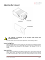
1
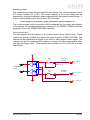
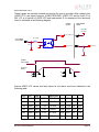
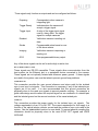
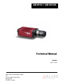
GX1910 / GX1910C
Technical Manual
700058A
April 7, 2010
Allied Vision Technologies Canada
Inc.
101-3750 North Fraser Way
Burnaby, BC
V5J 5E9 / Canada
Table of Contents
Table of Contents.............................................................................................................2
Introduction ..................................................................................................................5
Precautions ..................................................................................................................5
Warranty ......................................................................................................................5
Specifications ...............................................................................................................7
Supported Features .....................................................................................................8
Mechanical...................................................................................................................9
Connections ............................................................................................................... 10
Cleaning the Sensor .................................................................................................. 16
Adjusting the C-mount ............................................................................................... 17
Network Card Configuration....................................................................................... 19
GigE Sample Viewer and Filter Driver ....................................................................... 23
Trouble Shooting ....................................................................................................... 24
Addendum ..................................................................................................................... 27
GX IO Schematic ....................................................................................................... 28
User Trigger Circuit Example ..................................................................................... 29
TV Zoom Lens Connection ........................................................................................ 30
Video Iris Connection ................................................................................................. 31
Trigger Timing Diagram ............................................................................................. 32
Notes on Triggering ................................................................................................... 33
Camera Controls ........................................................................................................ 35
GX1910 Technical Manual
Page 2
Legal notice
For customers in the U.S.A.
(FCC Compliance Information)
This equipment has been tested and found to comply with the limits for a Class A digital device, pursuant to Part 15
of the FCC Rules. These limits are designed to provide reasonable protection against harmful interference when the
equipment is operated in a commercial environment. This equipment generates, uses, and can radiate radio
frequency energy and, if not installed and used in accordance with the instruction manual, may cause harmful
interference to radio communications. However there is no guarantee that interferences will not occur in a particular
installation. Operation of this equipment in a residential environment is likely to cause harmful interference.
You are cautioned that any changes or modifications not expressly approved in this manual could void your authority
to operate this equipment. The shielded interface cable recommended in this manual must be used with this
equipment in order to comply with the limits for a computing device pursuant to Subpart B of Part 15 of FCC Rules.
For customers in Canada
This digital apparatus complies with the Class A limits for radio noise emissions set out in the Radio Interference
Regulations.
Pour utilisateurs au Canada
Cet appareil numérique est conforme aux normes classe A pour bruits radioélectriques, spécifiées dans le Règlement
sur le brouillage radioélectrique.
Life support applications
These products are not designed for use in life support appliances, devices, or systems where malfunction of these
products can reasonably be expected to result in personal injury. Allied Vision Technologies customers using or
selling these products for use in such applications do so at their own risk and agree to fully indemnify Allied Vision
Technologies for any damages resulting from such improper use or sale.
Trademarks
Unless stated otherwise, all trademarks appearing in this document are the property of Allied Vision Technologies
and are fully protected by law.
Warranty
The information provided by Allied Vision Technologies is supplied without any guarantees or warranty whatsoever,
be it specific or implicit. Also excluded are all implicit warranties concerning the negotiability, the suitability for specific
applications or the non-breaking of laws and patents. Even if we assume that the information supplied to us is
accurate, errors and inaccuracy may still occur.
Copyright
All text, pictures and graphics are protected by copyright and other laws protecting intellectual property. It is not
permitted to copy or modify them for trade use or transfer, nor may they be used on web sites.
Allied Vision Technologies Canada Inc. 1/2010
All rights reserved.
GX1910 Technical Manual
Page 3
Contacting Allied Vision Technologies
• Technical information:
http://www.alliedvisiontec.com
• Support:
[email protected]
Allied Vision Technologies GmbH (Headquarters)
Taschenweg 2a
07646 Stadtroda, Germany
Tel.: +49.36428.677-0
Fax.: +49.36428.677-28
e-mail: [email protected]
Allied Vision Technologies Canada Inc.
101-3750 North Fraser Way
Burnaby, BC, V5J 5E9, Canada
Tel: +1 604-875-8855
Fax: +1 604-875-8856
e-mail: [email protected]
Allied Vision Technologies Inc.
38 Washington Street
Newburyport, MA 01950, USA
Toll Free number +1-877-USA-1394
Tel.: +1 978-225-2030
Fax: +1 978-225-2029
e-mail: [email protected]
GX1910 Technical Manual
Page 4
Introduction
The GX1910 series of cameras are sensitive, 63 frames per second, HDTV resolution,
Gigabit Ethernet cameras based on the Kodak KAI-02150 CCD sensor. These cameras
support the use of 1 or 2 gigabit Ethernet ports in a LAG configuration for higher
bandwidth requirements.
Precautions
READ INSTALLATION GUIDE CAREFULLY.
This document contains specific information which is necessary for the correct operation
and treatment of this product.
DO NOT OPEN THE CAMERA. WARRANTY IS VOID IF CAMERA IS OPENED.
This camera contains sensitive components which can be damaged if handled
incorrectly.
KEEP SHIPPING MATERIAL.
Poor packaging of this product can cause damage during shipping.
VERIFY ALL EXTERNAL CONNECTIONS.
Verify all external connections in terms of voltage levels, power requirements, voltage
polarity, and signal integrity prior to powering this device.
CLEANING.
This product can be damaged by some volatile cleaning agents. Avoid cleaning the
image sensor unless absolutely necessary. Please see instructions on sensor cleaning
in this document.
DO NOT EXCEED ENVIRONMENTAL SPECIFICATIONS.
See environmental specifications limits in the Specifications section of this document.
Warranty
AVT Canada Inc. provides a 2 year warranty which covers the replacement and repair
of all parts which are found to be defective in the normal use of this product. AVT
GX1910 Technical Manual
Page 5
Canada Inc. will not warranty parts which have been damaged through the obvious
misuse of this product.
GX1910 Technical Manual
Page 6
Specifications
Sensor Type
Kodak KAI-02150
Sensor Shutter Type
Progressive Interline
Image Resolution
1920 x 1080 pixels
Pixel Size
5.5µm x 5.5µm
Optical Format
2/3 inch
Lens Mount
C-mount with adjustable back focus
Color Sensor Filter Pattern†
Bayer
Full Resolution Frame Rate
63 fps
I/O
2 isolated inputs, 4 isolated outputs, RS-232 TX/RX,
video auto-iris, motorized iris, focus, and zoom
Power Requirements
Less than 5.6W using a single Gige port
Less than 6.7W using 2 Gige ports
Digitization
14 Bits
Trigger latency*
1.5µs
Trigger Jitter*
±0.5µs
Operating Temperature
0 to 50 Celsius***
Operating Humidity
20 to 80% non-condensing
Size and Weight
See mechanical diagrams
Hardware Interface Standard
IEEE 802.3 1000BASE-T, 100BASE-TX
Software Interface Standard
GigE Vision Standard 1.0
Regulatory
Conforms to CE, FCC, RoHS
†
Applies to GX1910C only.
††
Power consumption will increase with reduced ROI imaging, vertical binning, and color formats.
*
See Notes on Triggering in the Addendum.
***DUE TO THE SMALL PACKAGING AND HIGH SPEED OF THE GX CAMERAS, SPECIAL
CARE IS REQUIRED TO MAINTAIN A REASONABLE OPERATING TEMPERATURE. IF THE
CAMERA IS TO BE OPERATED IN A WARM ENVIRONMENT, IT IS SUGGESTED THAT THE
CAMERA BE MOUNTED ON A HEAT SINK SUCH AS A METAL BRACKET AND THAT THERE
IS SUFFICIENT AIR FLOW.
GX1910 Technical Manual
Page 7
Supported Features
Imaging Modes
free-running, external trigger, fixed rate, software trigger
Fixed Rate Control
0.001 fps to maximum frame rate
External Trigger Delay
0 to 60 seconds in 1 microsecond increments
External Trigger Event
rising edge, falling edge, any edge, level high, level low
Exposure Time
10 microseconds to 60 seconds in 1 microsecond increments
Gain
0 to 34dB
Region of Interest (ROI) independent x and y control with 1 pixel resolution
Horizontal Binning
1 to 8 pixels
Vertical Binning
1 to 8 rows
Pixel Formats
Mono8, Mono16*, Bayer8, Bayer16, Rgb24,
Yuv444, Bgr24, Rgba32, Bgra32, Bayer12Packed
Sync Out Modes
trigger ready, trigger input, exposing, readout, imaging,
strobe, GPO
*On monochrome versions only.
GX1910 Technical Manual
Page 8
Mechanical
GX C-MOUNT
GX1910 Technical Manual
Page 9
Connections
GX CONNECTION DIAGRAM
GX1910 Technical Manual
Page 10
GIGABIT ETHERNET PORTS
These ports conform to the IEEE 802.3 1000BASE-T standard for Gigabit Ethernet over
copper. It is recommended that CAT5E or CAT6 compatible cabling and connectors be
used for best performance. Cable lengths up to 100m are supported. For higher
bandwidth requirements, both ports can be used in a link aggregation group (LAG)
configuration.
GENERAL PURPOSE IO PORT
PIN
FUNCTION
1
POWER GROUND
2
EXTERNAL POWER
3
SYNC OUT 4
4
SYNC IN 1
5
SYNC OUT 3
6
SYNC OUT 1
7
USER GROUND
8
RS-232 RXD
9
RS-232 TXD
10
USER VCC
11
SYNC IN 2
12
SYNC OUT 2
GENERAL PURPOSE IO PORT AS SEEN FROM
BACK OF CAMERA
The General Purpose I/O port uses a Hirose HR10A-10R-12PB connector on the
camera side. The mating cable connector is Hirose HR10A-10P-12S. This connector
can be purchased from AVT Canada Inc. or from http://www.digikey.com. An openended cable assembly can also be ordered from AVT Canada Inc. (Part number 026033A).
See Addendum for more detail.
POWER GROUND
This is the main ground of the camera circuitry and will be the return path for the
external power source. This connection must be provided to operate the camera. The
conductor used for this connection must be adequate for the current consumption of the
camera. For best performance the connection for POWER GROUND should be
physically close to the EXTERNAL POWER connection.
GX1910 Technical Manual
Page 11
EXTERNAL POWER
This connection provides the main power for the camera. The camera operates from a
DC voltage between 5V to 24V. The current capacity of the power supply can be
estimated by dividing the camera’s power requirement by the external power voltage. It
is also recommended to factor this by about 50% as follows:
Power supply current capacity = (power specification / external voltage) x 1.5
The conductor used for this connection must be adequate for the current consumption
of the camera. For best performance the connection for EXTERNAL POWER should be
physically close to the POWER GROUND connection.
SYNC INPUTS (1 and 2)
The input signals allow the camera to be synchronized to some external event. These
signals are optically isolated and require the signal common (USER GROUND). The
camera can be programmed to trigger on the rising or falling edge of these signals. The
camera can also be programmed to capture an image at some programmable delay
time after the trigger event. These signals can be driven from 5V to 24V with a current
load of 5mA.
VDD+3.3
180R
1/10W
8
VCC
S
1
D
5V TO 24V
IF = 5mA
PIN 4. SYNC IN 1
7
G
MMBF4393LT1G
2
TO CAMERA
LOGIC
3
6
180R
1/10W
4
GND
S
D
5V TO 24V
IF = 5mA
PIN 11. SY NC IN 2
5
HCPL-063L
G
MMBF4393LT1G
PIN 7. USER GND
GX1910 Technical Manual
Page 12
SYNC OUTPUTS (1 to 4)
These signals are optically isolated and require the user to provide a high voltage level
(USER VCC) and signal common (USER GROUND). USER VCC can be from 5V to
24V. ICC is a function of USER VCC and load resistor R. An example of the functional
circuit is indicated in the following diagram.
CAMERA
CIRCUIT
USER TRIGGER
CIRCUIT
5V TO 24V
VCC-USER
PIN 10. USER VCC
IF = 5mA
3.3V CAMERA
LOGIC SIGNAL
16
1
442R
2
100K
15
SY NC OUT
V LOAD
TLP281-4GB
R
GND-USER
CAMERA
LOGIC SIGNAL
SYNC OUT
SIGNAL
T3
T1
T2
T4
Various USER VCC values and load values for the above circuit are indicated in the
following table:
USER USER
VCC
ICC
R
LOAD
V LOAD
R POWER
DISSIPATION
T3
T4
500Ω
4.1V
32mW
1.5µs 6.5µs
2µs
14µs
4.8mA 1KΩ
4.8V
23mW
1.5µs
17µs 40µs
12V 9.2mA 1.2KΩ
11.2V
101mW
1.5µs 11.2µs 2µs
12V 4.9mA 2.4KΩ
11.8V
58mW
1.5µs 8.5µs 17µs 55µs
24V 9.5mA 2.4KΩ
23.2V
217mW
1.5µs 22µs
24V
23.8V
120mW
1.5µs 12µs 17µs 105µs
5V
5V
8mA
5mA 4.8KΩ
GX1910 Technical Manual
T1
T2
5µs
2µs
20µs
37µs
Page 13
These signals only function as outputs and can be configured as follows:
Exposing
Corresponds to when camera is
integrating light.
Trigger Ready
Indicates when the camera will
accept a trigger signal.
Trigger Input
A relay of the trigger input signal
used to “daisy chain” the trigger
signal for multiple cameras.
Readout
Valid when camera is reading out
data.
Strobe
Programmable pulse based on one
of the above events.
Imaging
Valid when camera is exposing or
reading out.
GPO
User programmable binary output.
Any of the above signals can be set for active high or active low.
RS-232 RXD and RS-232 TXD
These signals are RS-232 compatible. These signals allow communication from the
host system via the Ethernet port to a peripheral device connected to the camera.
These signals are not optically isolated and reference power ground. If these signals
are used in the system, care must be taken to prevent ground loop problems.
USER GROUND
This connection provides the user ground reference and return path for the isolated
sync in and sync out signals. This connection is necessary if any of the isolated sync
signals are to be used. It is also recommended that this ground connection be
physically close to the used sync signals to prevent parasitic coupling. For example, a
good cable design would connect the required signal on one conductor of a twisted pair
and the isolated ground on the second conductor of the same twisted pair.
USER VCC
This connection provides the power supply for the isolated sync out signals. The
voltage requirement is from 5V to 24V DC. The current requirement for this supply is a
function of the optical isolator collector current and the number of sync outs used in the
system. See the SYNC OUTPUT section for more detail. To prevent parasitic coupling this
connection should be physically close to the used SYNC OUT signals and USER
GROUND.
GX1910 Technical Manual
Page 14
LENS CONTROL PORT
PIN
FUNCTION
1
IRIS +
2
IRIS -
3
FOCUS +
4
FOCUS -
5
ZOOM +
6
ZOOM -
7
AUTO IRIS SIGNAL
8
GROUND
LENS CONTROL PORT AS SEEN FROM BACK OF
CAMERA
This connector provides the signals necessary to control the iris, focus, and zoom of
most commercially available TV Zoom lenses. The camera can be configured to
operate lenses with unipolar voltage requirements of 6V up to 12V or lenses which
operate with bipolar voltages from ±6V up to ±12V. This voltage level can be controlled
through software. The default voltage will be set to 6V. The current capacity for each
axis is 50mA.
CARE MUST BE TAKEN NOT TO EXCEED THE LENS MANUFACTURERS
VOLTAGE SPECIFICATION.
This connector also provides the signals necessary to operate a video auto iris type of
lens.
The lens control connector is a Hirose 3260-8S3. The mating cable connector is Hirose
3240-8P-C(50). This connector can be purchased from AVT Canada Inc. or from
http://www.digikey.com.
See Addendum for more detail.
GX1910 Technical Manual
Page 15
Cleaning the Sensor
DO NOT CONTACT CLEAN SENSOR UNLESS ABSOLUTELY NECESSARY.
Identifying Debris
Debris on the image sensor or optical components will appear as a darkened area or
smudge on the image that does not move as the camera is moved. Do not confuse this
with a pixel defect which will appear as a distinct point.
Locating Debris
Before attempting to clean the image sensor, it is important to first determine that the
problem is due to debris on the sensor window. To do this you should be viewing a
uniform image, such as a piece of paper, with the camera. Debris will appear as a dark
spot or dark region that does not move as the camera is moved. To determine that the
debris is not on the camera lens, rotate the lens independent of the camera. If the spot
moves as the lens moves, then the object is on the lens -not on the image sensor- and
therefore cleaning is not required. If the camera has an IR filter, then rotate the IR filter.
If the object moves then the particle is on the IR filter not the sensor. If this is the case
remove the IR filter carefully using a small flat head screw driver. Clean both sides of
the IR filter using the same techniques as explained below for the sensor window.
DO NOT TOUCH ANY OPTICS WITH FINGERS. OIL FROM FINGERS CAN
DAMAGE FRAGILE OPTICAL COATINGS.
Cleaning with Air
If it is determined that debris is on the sensor window, then remove the camera lens,
and blow the sensor window directly with clean compressed air. If canned air is used,
do not shake or tilt the can prior to blowing the sensor. View a live image with the
camera after blowing. If the debris is still there, repeat this process. Repeat the
process a number of times with increased intensity until it is determined that the
particulate cannot be dislodged. If this is the case then proceed to the contact cleaning
technique.
Contact Cleaning
Only use this method as a last resort. Use 99% laboratory quality isopropyl alcohol and
clean cotton swabs. Dampen the swab in the alcohol and gently wipe the sensor in a
single stroke. Do not reuse the same swab. Do not wipe the sensor if the sensor and
swab are both dry. You must wipe the sensor quickly after immersion in the alcohol, or
glue from the swab will contaminate the sensor window. Repeat this process until the
debris is gone. If this process fails to remove the debris, then contact AVT Canada Inc.
GX1910 Technical Manual
Page 16
Adjusting the C-mount
THE C-MOUNT IS ADJUSTED AT THE FACTORY AND SHOULD NOT
REQUIRE ADJUSTING.
If for some reason, the C-mount requires adjustment, use the following method.
Loosen Locking Ring
Use an adjustable wrench to loosen locking ring. Be careful not to scratch the camera.
When the locking ring is loose, unthread the ring a few turns from the camera face. A
wrench suitable for this procedure can be provided by AVT Canada Inc. (P/N 110048A).
Image to Infinity
Use a c-mount compatible lens that allows an infinity focus. Set the lens to infinity and
image a distant object. The distance required will depend on the lens used but typically
30 to 50 feet should suffice. Make sure the lens is firmly threaded onto the c-mount
GX1910 Technical Manual
Page 17
ring. Rotate the lens and c-mount ring until the image is focused. Carefully tighten
locking ring. Recheck focus.
GX1910 Technical Manual
Page 18
Network Card Configuration
Operating GigE Vision GX cameras using multiple network adaptors
The GX series cameras offer two Gigabit Ethernet ports for image data transfer and control.
Users can connect one or both ports on the GX to Ethernet adapter ports on a host computer.
Connecting both ports will increase the available bandwidth to 240 MB/sec, allowing higher
frame rates and resolutions than a single port connection.
GX cameras can be operated in single port and dual port configurations. The dual port
approach requires the host computer to configure a Link Aggregate Group (LAG). A LAG
configuration combines multiple Ethernet ports into a single data channel.
1. Install a dual port network card in the host computer. To achieve full camera
performance, you should use a Gigabit Ethernet card that supports "Jumbo frames" of
at least 9KB size.
2. Once installed, open your “Network Connections” (Start -> Control Panel->Network
Connections) and right-click on one of the two network connection corresponding to the
card that was just installed.
3. Select “Properties” from the contextual menu that
appears when you right click the network
connection icon. This will open the properties
window.
4. In the properties window, click the “Configure” button. Select the “Advanced” tab. In
the “Property” list make the following changes:
(a) select “Jumbo Frames” and change the value to 9014 bytes or higher.
(b) select “Receive Descriptors” on the same list and change the value to 512
(c) select "Performance Options" and set "Interrupt Moderate Rate" to "Extreme"
GX1910 Technical Manual
Page 19
5. Click on “OK” to validate your change (the “Properties” window will close). The
Property list will be different between different types/brands of gigabit Ethernet interface
cards. If "Jumbo Frames" does not appear in this list, then your card probably does not
support it. If your card does not support Jumbo Frames, then your CPU usage will be
higher.
6. Re-open the "Properties" of the PRO/1000 GT adapter by right-clicking the Local Area
Connection "Intel® PRO/1000 GT" network connection icon in the Network Connections
window and select the "Advanced" tab at the top of the Properties dialog.
7. In the "Windows Firewall" section, select "Settings". In the
Settings dialog choose "Off" to turn off the Windows
firewall. The camera will not work if the firewall is active. If
you installed the AVT/Prosilica GigE filter driver, this step
is not required.
8. Perform Steps 1 – 8 for the other Ethernet adapter port that will be dedicated to the GX
camera network.
9. The next section will provide instructions for configuring the Link Aggregate Group
(LAG) to combine the two ports dedicated to the GX network.
Open your “Network Connections” (Start -> Control Panel->Network Connections) and
right-click on one of the two network connection corresponding to the card that was just
installed. Select “Properties” from the contextual menu that appears when you right
click the network connection icon. This will open the properties window. In the
properties window, click on “Configure” button in order to create a Link Aggregate
Group (LAG) between the two ports.
10. Select the “Teaming” tab (analogous to LAG), enable
“Team this adapter with other adapters and click on
the “New Team” button.
11. Specify a name for the Team (Link Aggregate Group).
This should be something that will distinguish this
GX1910 Technical Manual
Page 20
adapter from others in your system. Click “Next” to continue.
12. Select the two Ethernet ports to which the GX
camera will be connected. These ports will
form our LAG or TEAM. Click “Next” to
continue.
13. Choose “Static Link Aggregation”. Click
“Next” to continue.
14. The LAG group will now be configured. You may
be asked to permit the “AVT_Prosilica GigE Vision
Filter Miniport” installation on the new LAG adapter.
Click “Continue Anyway”.
GX1910 Technical Manual
Page 21
15. Once completed the properties of the TEAM (LAG) that has just been created will
appear. A new Network Connections Icon corresponding to the LAG group is created.
You have now completed the Link Aggregate Group configuration.
16. Reboot the system and install GigE Sample Viewer.
GX1910 Technical Manual
Page 22
GigE Sample Viewer and Filter Driver
o Download GigE Sample Viewer from www.alliedvisiontec.com. This will install the
Sample Viewer application program, drivers, and optionally the AVT/Prosilica Filter
Driver. The Filter Driver will improve CPU performance and is recommended.
o Plug in the GX camera Ethernet cable(s) and power. Verify that the Green LED is a
solid green. Run Sample Viewer. It will take a few seconds for the camera to be
recognized, especially if your camera is in DHCP mode. If the camera does not
appear after one minute, see the Trouble Shooting section of this document.
o In Sample Viewer, select the wrench icon to change camera settings. See the
Camera Controls Addendum for description of each setting. Select the eye icon to
stream images. If the camera is not imaging, see the Trouble Shooting section of
this document.
Figure 1. GigE Viewer application window.
GX1910 Technical Manual
Page 23
Trouble Shooting
Is the camera getting power?
The Green LED is the camera power indicator. If unlit, check the power adaptor. If
possible, swap with one that is known to work. If using a custom power adaptor, be sure
the adaptor supports the voltage and power requirements of the camera . If the LED still
does not light up, contact AVT Canada Inc. support.
Is the camera powered, but not detected in SampleViewer?
Damaged or poor quality Ethernet cabling can result in no cameras found, dropped
packets, decreased bandwidth, and other problems. Use Cat5e or better cabling known
to work.
Configure your NIC as outlined in “Gigabit Ethernet Setup For Windows”. It should have
an IP address of 169.254.x.x, Subnet Mask: 255.255.0.0. This is the AutoIP address
range. If your NIC has no access to a DHCP server, the camera will still be auto
assigned an IP address. There should be no gateway on your NIC.
Connect a single camera directly to your NIC, no hub/switch, and run the prosilica IP
Configuration
utility
(Start>Programs>Prosilica>GigEIPConfig
or
C:\Program
Files\Prosilica\GigEViewer\ipconfig.exe). You may need to wait up to 30 sec for camera
to appear.
A camera in DHCP (AutoIP fallback) mode.
•
Camera is listed: Your camera and NIC must be on the same subnet, e.g.: NIC:
IP 169.254.23.2 Subnet Mask: 255.255.0.0, Camera IP: 169.254.43.3 Subnet Mask:
255.255.0.0.
GX1910 Technical Manual
Page 24
The following example is not on the same Subnet: NIC IP 169.250.23.2 Subnet Mask:
255.255.255.0, CamIP 169.254.13.0 Subnet Mask: 255.255.0.0. This can happen if you
use a non AutoIP range on your NIC and it doesn’t have access to a DHCP server.
Either change your NIC IP to be in the AutoIP range, or fix the camera IP address to be
on the same subnet as your NIC.
•
Camera is not listed, or flashing “Camera Unavailable”: There may be multiple
NICs on your system set to the same subnet. The camera can not know which card to
resolve to. Change the IP address of your NIC.
If you are still having problems, type: ipconfig /all in a windows command prompt, and
send a screenshot to [email protected].
Ipconfig /all screenshot
Is the camera listed in SampleViewer but can’t acquire images?
Reset your camera settings to factory default: with ConfigFileIndex = Factory, click the
ConfigFileLoad button.
While streaming, check your Stats:
GX1910 Technical Manual
Page 25
All stats 0 while streaming. Firewall likely blocking traffic
•
•
•
All stats 0. Likely a firewall is blocking incoming traffic. Disable your firewall. Check your
camera trigger settings. Many camera trigger modes require a software or hardware
trigger event to capture frames.
Packets are incoming, but all dropping. Be sure you have JumboFrames enabled on
your NIC. Otherwise, decrease your PacketSize setting to 1500.
All packets completing as normal, but black image. Check ExposureValue,
ExposureMode, and be sure your scene is suitably lit.
If you are still having problems acquiring images, please send your camera settings file
(click on the disk icon in SampleViewer) to [email protected].
Saving camera setting file
GX1910 Technical Manual
Page 26
Addendum
GX1910 Technical Manual
Page 27
VDD+3.3
4.7K
VCC
180R
1/10W
8
4.7K
5
VDD+3.3
VCC
CAMERA LOGIC SY NC IN 1
6
S
1
1
D
5V TO 24V
IF = 5mA
7
MMBF4393LT1G
G
2
3
CAMERA LOGIC SY NC IN 2
4
3
6
180R
1/10W
4
S
D
5V TO 24V
IF = 5mA
GND
PIN
PIN
PIN
PIN
PIN
PIN
PIN
PIN
PIN
PIN
PIN
PIN
1. POWER GROUND
2. EXTERNAL POWER
3. SYNC OUT 4
4. SYNC IN 1
5. SYNC OUT 3
6. SYNC OUT 1
7. USER GROUND
8. RS-232 RXD
9. RS-232 TXD
10. USER VCC
11. SYNC IN 2
12. SYNC OUT 2
1
9
10
2
8
3
7
4
11
12
6
5
HIROSE HR10A-10R-12PB
GND
HCPL-063L
G
5
2
NC7WZ14P6X
3.3V LOGIC
442R
16
1
CAMERA LOGIC SY NC OUT 1
IF = 5mA
2
100K
15
SYNC OUT 1
TLP281-4GB
442R
14
3
CAMERA LOGIC SY NC OUT 2
IF = 5mA
4
100K
13
SYNC OUT 2
TLP281-4GB
442R
12
5
CAMERA LOGIC SY NC OUT 3
IF = 5mA
6
100K
11
SYNC OUT 3
TLP281-4GB
442R
10
7
CAMERA LOGIC SY NC OUT 4
IF = 5mA
8
100K
9
TLP281-4GB
SYNC OUT 4
MMBF4393LT1G
GX IO Schematic
GX1910 Technical Manual
VDD+3.3
Page 28
CABLE SIDE
POWER GROUND
EXTERNAL POWER
SYNC OUT 4
SYNC IN 1
SYNC OUT 3
SYNC OUT 1
USER GND
VDD+5
5V POWER
CIRCUIT
USER VCC
SYNC IN 2
SYNC OUT 2
1
2
3
4
5
6
7
8
9
10
11
12
9
1
10
8
2
7
3
6
12
11
4
5
HIROSE HR10A-10P-12S
USER LOGIC SYNC IN 1
USER LOGIC SYNC IN 2
USER
USER
USER
USER
LOGIC
LOGIC
LOGIC
LOGIC
SY NC
SY NC
SY NC
SY NC
OUT 1
OUT 2
OUT 3
OUT 4
2
4
6
8
9
7
5
3
1A1
1A2
1A3
1A4
1Y 1
1Y 2
1Y 3
1Y 4
2Y 1
2Y 2
2Y 3
2Y 4
2A1
2A2
2A3
2A4
1OE
2OE
VCC
GND
NOTES:
1. CAMERA POWER = 5V TO 24V
2. CAMERA POWER DOES NOT NEED TO BE THE SAME AS USER VCC.
3. CAMERA GND DOES NOT NEED TO CONNECT TO USER GND.
4. USER VCC MUST HAVE CURRENT CAPACITY TO SUPPLY IC
CURRENT FOR EACH SYNC OUT USED.
18
16
14
12
11
13
15
17
1
19
20
10
SN74ABT244APWR
VDD+5
1K
0.1u
10V
1K
1K
1K
User Trigger Circuit Example
This diagram indicates one example of a 5V TTL based user trigger circuit.
GX1910 Technical Manual
CAMERA POWER
Page 29
ZOOMTV ZOOM LENS
BIPOLAR TYPE
FOCUS+
FOCUSIRIS+
IRIS-
IRIS-
2
FOCUS-
4
ZOOM-
6
COMMON
8
1
IRIS+
3
FOCUS+
5
ZOOM+
7
COMMON
HIROSE 3240-8P-C(50)
ZOOM
TV ZOOM LENS
UNIPOLAR TYPE
FOCUS
IRIS
COMMON
COMMON
2
COMMON
4
COMMON
6
COMMON
8
1
IRIS
3
FOCUS
5
ZOOM
7
HIROSE 3240-8P-C(50)
NOTES:
1. CURRENT CAPACITY PER AXIS = 50mA.
2. VERIFY LENS VOLTAGE SETTING ON CAMERA DOES NOT EXCEED LENS VOLTAGE SPECIFICATION.
TV Zoom Lens Connection
GX1910 Technical Manual
ZOOM+
Page 30
1
2
3
4
5
6
7
8
9
10
11
12
9
1
10
8
2
7
3
6
12
11
4
5
HIROSE HR10A-10P-12S
1
2
3
4
5
6
7
8
VIDEO
AUTO-IRIS
LENS
1
2
3
4
1
2
3
4
JEITA CONNECTOR
LENS POWER
VIDEO SIGNAL
LENS GROUND
HIROSE 3240-8P-C(50)
Video Iris Connection
GX1910 Technical Manual
POWER GROUND
12V POWER
POWER GROUND
12V_POWER
Page 31
Trigger Timing Diagram
GX1910 Technical Manual
Page 32
Notes on Triggering
Definitions
o User Trigger is the trigger signal applied by the user.
o Logic Trigger is the trigger signal seen by the camera internal logic.
o Tpd is the propagation delay between the User Trigger and the Logic Trigger.
o Exposure is high when the camera image sensor is integrating light.
o Readout is high when the camera image sensor is reading out data.
o Trigger Latency is the time delay between the User Trigger and the start of
Exposure.
o Trigger Jitter is the error in the Trigger Latency time.
o Trigger Ready indicates to the user that the camera will accept the next trigger.
o Registered Exposure Time is the Exposure Time value currently stored in the
camera memory.
o Expose Start Delay is the delay time from the start of Exposure to valid Trigger
Ready. It is the Registered Exposure Time subtracted from the Readout time and
indicates when the next Exposure cycle can begin such that the Exposure will end
after the current Readout.
o Interline Time is the time between sensor row readout cycles.
o Imaging is high when the camera image sensor is either exposing and/or reading out
data.
o Idle is high if the camera image sensor is not exposing and/or reading out data.
Rules
o The User Trigger pulse width should be at least three times the width of the Trigger
Latency as indicated in the Specifications section of this document.
o The end of Exposure will always trigger the next Readout.
o The end of Exposure must always end after the current Readout.
o The start of Exposure must always correspond with the Interline Time if Readout is
true.
o Expose Start Delay equals the Readout time minus the Registered Exposure Time.
Triggering during the Idle State
o For applications requiring the shortest possible Trigger Latency and the smallest
possible Trigger Jitter the User Trigger signal should be applied when Imaging is
false and Idle is true.
o In this case, Trigger Latency and Trigger Jitter are as indicated in the Specifications
section.
GX1910 Technical Manual
Page 33
Triggering during the Readout State
o For applications requiring the fastest triggering cycle time whereby the camera
image sensor is exposing and reading out simultaneously, then the User Trigger
signal should be applied as soon as a valid Trigger Ready is detected.
o In this case, Trigger Latency and Trigger Jitter can be up to 1 line time since
Exposure must always begin on an Interline boundary.
GX1910 Technical Manual
Page 34
Camera Controls
For the latest, up to date camera controls, see AVT Camera and Driver
Attributes.pdf at http://www.alliedvisiontec.com
GX1910 Technical Manual
Page 35