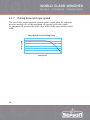
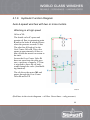
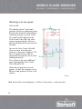
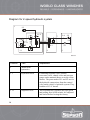
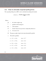
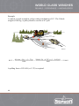
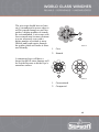
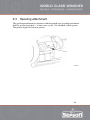
1
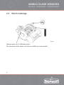
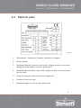
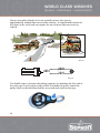
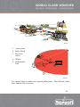
Vehicle Recovery Winch - hydraulically driven
SEPDURANCE
SEPMATIC
FORCEMATIC
SEPGAIN
Original User Manual
1
Introduction
1.1
General
Its SEPSON’s objective, focus and single purpose to build reliable,
dependable and uncomplicated winches that will require a minimum of
maintenance and are simple to repair if this is ever needed. They are quickly
and easily attached on any vehicle chassis.
SEPSON hydraulic vehicle recovery winches from the product groups
– SEPDURANCE, SEPMATIC, FORCEMATIC as well as the worm gear
driven SEPGAIN series, will meet all rescue and recovery requirements
The SEPDURANCE winches represent the core of our range of drum winches
and are characterized by these features.
All drum winches:
•
have drum and housing made of nodular cast iron for added strength and
structural integrity
•
have the free spooling feature to easily allow a manual unspooling of the
wire rope and a unique 2-speed feature controlled by a hydraulic valve
system is also standard on all models with a pulling force of 150 kN and
above
•
are equipped with a spring applied, pressure release multi-disk brake and
the optimal drum-to-wire-rope diameter ratio of minimum 10:1 which
significantly increases the useful life of the rope and reduces operating
expenses.
The SEPMATIC winches are the next step up on the ladder to higher
performance and feature an integrated spooling attachment.
The FORCEMATIC range is our most advanced family of winches which are
have been equipped with a unique feature that maintains a constant pulling
force on the wire rope regardless of its layer on the rope drum.
3
1.2
About this manual
This manual contains important data concerning the maintenance, installation
and operation of SEPSON winches.
Should anyone assigned the task to attach the winch on a vehicle be
uncertain about how to perform the task, please contact SEPSON.
The information in this manual is based on current information available to
SEPSON at this time. Under no circumstance, should this information
override or replace national or international statutory instructions, regulations
and safety precautions.
Caution
This symbol indicates that the information in a relevant
paragraph must be observed and understood. Please contact
SEPSON if there is any doubt regarding a “caution” or
“warning” frame.
WARNING
This warning symbol alerts to a clear and present danger and
must be observed and understood at all times. Do not proceed
with the winching operation if there is any doubt about the
meaning of this warning!
4
2
Safety
The winch must only be used for vehicle recovery and loading.
2.1
Introduction
This introduction describes and explains the safety precautions that must be
observed and provides useful and necessary information.
Read this chapter very carefully. It is important to fully understand its content
and purpose. It concerns your safety as well as the safety of others around you
in the working area of the rescue and recovery operation and the safe
utilization of the winch.
Familiarize yourself with the winch by practising its use before attempting to
save or rescue a vehicle. This is important and will help you understand its
different functions and ensure that you will be able to operate the equipment
with optimal safety.
5
2.2
Safety symbols
Signs with the symbols below shall be attached on or at the winch operating
device(s). If a remote control is used the symbols shall be attached on the hand
held control unit.
General warning
Eye protection must be used
Head protection must be used
Hand protection must be used
Safety boots must be used
Read the manual before operating the winch
6
OUT
Winching out (attached at the direction control
valve - remote control)
IN
Winching in (attached at the direction control
valve - remote control)
Freespool clutch (attached at the freespool
control)
A label showing drum rotation when
spooling in the rope on the drum is
attached on the winch by Sepson prior
to shipment.
Sepson is delivering a sheet with self gluing symbols with the winch to be
attached on the operating device by the winch installer.
7
2.3
Winch markings
0078-01
Machine plate (See 2.4 Machine plate).
The placement of the marks varies between different winch models.
8
2.4
Machine plate
0079-01
1.
Winch model – Sepdurance, Sepmatic, Forcematic or Sepgain
2.
Product number
3.
Maximum allowed oil pressure to the winch. A higher pressure can seriously
damage the winch and give excessive pulling force
4.
Maximum allowed oil flow to the winch. A higher oil flow can seriously damage the winch
5.
Required electrical current for the winch if applicable
6.
Diameter of steel wire rope
7.
Maximum length of steel wire rope on the winch
9
8.
Minimum breaking load (MBL) for the winch wire rope stated by the wire rope
manufacturer
9.
Recommended oil or grease for the winch
10.
Manufacturing year
11.
Manufacturing number
12.
Weight of winch excluding steel wire rope
13.
Maximum pulling force on the bottom rope layer
14.
Maximum pulling force on the top rope layer
15.
Maximum allowed load weight when lifting on the bottom rope layer
16.
Maximum allowed load weight when lifting on the top rope layer
17.
Maximum allowed number of rope layers on the winch drum
18.
If Yes is marked does the specified wire rope comply with EU-standard
19.
If No is marked does not the specified wire rope comply with EU-standard and
the winch is delivered for use in countries outside the European Union with
other safety standard
10
2.5
General information
WARNING
Operation of the winch requires a skilled operator.
Any use of the winch may create risks of injuries to the operator and the
general safety of people in the area as well as damage to the winch itself and
other equipment used in connection with its operation.
It is only the operator’s awareness of the necessary safety precautions and
his/her sound judgment that can eliminate or reduce the risks of personal
injuries.
It is the responsibility of the operator to ensure that all appropriate precautions
are taken as required by the working environment and conditions in each
individual case.
Neither this document nor observing and applying its instructions absolve the
operator or owner from their joint responsibilities to ensure the actual
implementation of all precautions or the observance of all warnings.
If anyone becomes aware of any SEPSON supplied product or SEPSON
originated design that can create a risk to an individual working with or within
the vicinity of the product, it is an obligation to contact SEPSON immediately.
It is the user’s responsibility to make all relevant hazard identifications and
risk assessment of all activities associated with the use of both the product and
this document.
It is solely the user’s and the owner’s joint responsibility to provide a safe
working environment and to provide the necessary safety equipment and
ensure that everybody who is depending on this document, understands the
instructions, warnings and caution and that they are able to operate the
equipment in accordance with these instructions.
Should an operator lack the knowledge, experience or skills to work in
accordance with the safety or other instructions in this document, immediate
assistance should be requested from SEPSON. Technical assistance sought
from SEPSON will be subject to SEPSON terms and conditions.
11
2.6
Personal Protective Equipment
It is absolutely essential that the operator uses the appropriate and required
safety equipment when working with the equipment.
This includes:
1. Head protection (Hard hat)
2. Protective clothing
3. Hand protection (Heavy duty gloves when handling with the rope and
rubber gloves when working with oil)
4. Eye protection (Goggles)
5. Safety boots (Steel tipped and slip resistant sole)
1
4
2
3
5
0063-01
Protective clothing should protect the operator(s) against oil and shield from
accidental contact with the wire rope. Avoid loose clothing that may be caught
in the winch or the wire rope and cause serious injury.
Personal safety equipment does not eliminate the risk of injury but reduces the
risk and effects in case of an accident. It is only the user’s awareness of all
safety risks and his/her own judgment that will provide the necessary safety
margins against personal injury.
12
2.7
Precautions
Always make sure that nobody unauthorized is in the hazard area marked with
yellow and absolutely no one in the high risk zone marked with red in these
illustrations before starting the winch operation.
0020-01
0020-03
13
Always follow and observe SEPSON’s and the vehicle manufacturer’s advice
and instructions with regards to the recommended location of the winch.
The hydraulic system and its applications require care and cleanliness.
Always observe and respect SEPSON assembly and installation instructions.
WARNING
Never use the winch to move people and never use it as a hoist
to lift objects.
WARNING
Keep hands clear of the wire rope and all attaching components during installation, pulling process and when spooling
the wire rope in or out on the drum. Always handle the wire
rope by the rope end when spooling out the rope by hand.
The first step is to create a safe working environment for each specific pull.
There are several aspects to consider depending on restrictions imposed by the
surroundings and the locations of the vehicles.
–
Remove any objects that may be blocking the operation or prevent a clear
view of the pull path.
–
Try to place the winch at in a straight line in front of the load.
–
Never try to pull the load sideways.
–
If necessary, use pulley blocks or other devices to change the pulling
direction or its angle to the winch.
–
Take all necessary time to plan the pulling operation and gather available
information such as the load (weight) and the surroundings (surface
condition) before the operation takes place.
–
Consider all important issues that might impact the winching operation
and which may be important factors in calculating the pull and in determining the need for special equipment.
14
–
Always wear heavy duty protective gloves when handling the rope and
never let it slide through the palm of your hands while spooling, because
wire strands may cause painful injury.
–
If a remote control is installed, always keep the control unit with you
when leaving the winch unattended.
–
Always attach the wire rope to a point on the object that will support the
winch’s maximum capacity.
WARNING
Always handle the wire rope with gloves and pull on any device
attached to the rope end when spooling in or out by hand.
WARNING
When pulling out the rope, always leave at least the length of
three (3) revolutions on the drum.
Caution
Always pull out the wire rope manually with the drum in the
free spooling position. Never run out the rope under power.
Caution
Never hook the wire rope on to itself, it will cause damage.
Caution
Never fill the hydraulic oil tank with more than 80% of capacity
to leave 20% space for the liquid for heat expansion.
15
Caution
Always put a load on the rope when spooling to the drum
otherwise the rope will not spool correctly.
WARNING
Always inspect the wire rope’s attaching point at the load side
and its condition before operating the winch.
WARNING
Damaged wire ropes or attaching devices must be replaced
before the pull.
WARNING
Always stand clear of the rope and respect the danger zone.
–
Make sure everybody is aware of your intention to pull the load and
outside the danger zone.
WARNING
Make sure that the rope is slack before unhooking after the
pull. There is a clear danger of injury from the rope’s rotation.
16
3
Installation
3.1
General
The winch is designed for pulling operations in recovery and rescue and is
designed for mounting on a vehicle chassis only. Please refer to the technical
information for more detailed specification on this particular winch model.
3.2
Mounting on vehicle
The winch is either mounted with a mounting plate or directly to the vehicles
chassis. When a mounting plate is required, the plate must support the force of
twice the maximum pulling force of the winch.
Refer to instructions about the use and dimensions of a mounting plate in the
Technical information for your winch. If in doubt, always seek the advice and
instructions from both SEPSON and the vehicle’s manufacturer.
–
The emergency stop shall cut out the power supply to the winch(es).
–
Never mount operating device close to the exhaust pipe(s).
–
Handholds and platform for maintenance work shall be installed if needed
for safe work.
SEPSON is not liable for the winch installation on the vehicle.
17
3.3
Lifting the winch
Lifting straps
Lifting eye
0014-02
0070-01
Separate the straps on the drum
as much as possible.
Caution
The winch is too heavy for handling by hand. Use an adequate
lifting device and do not place lifting straps around the
hydraulic motor or the hydraulic valve block. Please refer to the
technical information to obtain the exact weight of this winch
1. Remove the rope from the drum and refer to instructions under rope
installation.
2. Create a rope sling around the drum.
3. Place the loop sling into the lifting device.
4. Check the balance before lifting.
5. Lift the winch.
If the winch is supplied with thread bolt holes for lifting eyes use lifting eyes.
18
3.4
Hydraulic installation
Auto 2-speed block
Single speed block
V
2
V
1
M
V
2
V1
V
1
V2
0033-01
0066-01
WARNING
All seals must be in place to protect the operator and anybody
else in the area against an escape of high oil pressure.
1. Connect the directional control valve and the winch by the ports V1 and
V2 on the hydraulic block.
2. Inspect and test all tubing, hoses and connection points for oil leakage.
If the directional control valve is attached to the winch, connect the pressure
hose/tube to the pressure inlet and the return hose/tube to the oil outlet on the
control valve.
The directional control valve must have an open centre; otherwise the winch
safety brake will not operate properly or not at all.
Make sure that the hydraulic system is set to not deliver higher oil pressure
and oil flow as listed in the technical information section for the winch.
19
3.5 Pneumatic or hydraulic free spooling control
installation
Connect the freespooling control to
the winch according to the circuit.
It is a 1/4” threaded connection on
the winch’s freespooling cylinder.
3
- If the winch has a pneumatic
freespooling control, the air
pressure shall be 6-10 bar.
2
- If the winch has a hydraulic
freespooling control the oil pressure
must not exceed 40 bar.
Check freespool clutch.
1
0018-01
1. Air/oil supply
2. Control Valve
3. Free spooling valve
Minimum allowed movement of the freespool clutch
Art. No
mm
Art. No
mm
73.06- 73.0760.08- 60.15-60.16-
16
73.09-
9
63.01- 63.02-
21
63.53-
10
63.35-
11
62.56-
12
63.31-
9
63.34-
13
The different connection points for the Sepson winch groups are shown below,
the arrow points at the connection point.
20
Art.no
Art.no
73.0673.0760.0860.1560.16-
73.09-
0049-01
63.0163.02-
0050-01
63.53-
0051-01
63.35-
0052-01
62.5462.56-
0053-01
0054-01
63.3163.34-
0019-01
21
3.6
Rope installation
Caution
Always wear protective gloves when handling the rope.
Never install a wire rope that does
not meet the requirements in
technical information for this
winch.
The new rope must be uncoiled
from the spool on the ground prior
to installation.
0024-01
22
Wedge Lock
1. Thread the end of the rope
through the wedge rope grip
from its narrow end.
2. Bend the rope end around the
wedge rope grip and form a
loop.
3. Place the rope key inside the
loop.
4. Insert the rope key inside the
rope pocket.
0026-01
5. Hold the rope firmly inside the
pocket and pull firmly to insert
the rope key and rope loop
inside the slot on the drum.
6. Make certain that both the rope
key and the loop are entirely
inserted into the rope pocket on
the drum.
7. Now wind the rope on carefully
on the drum while maintaining
a pull on the rope itself. Make
certain that the rope ends wind
up close together.
23
Screw Lock
1. Thread the end of the rope
through the hole furthest from
the drum flange and pull about
1 metre through (enough for 3
turns on the drum).
2. Wind the free end 3 turns on to
the drum toward the flange by
hand as tightly as possible.
3. Pass the free end through the
hole nearest to the flange and
make sure it goes right to the
end of the hole.
4. Secure the end of the rope in
this hole by tightening the
locking screw.
5. Now wind the rope on carefully
on the drum while maintaining
a pull on the rope itself. Make
certain that the rope ends wind
up close together.
0055-01
Wind the rope on the drum to exit either above or below as required.
0056-01
24
3.7
Electrical installation
WARNING
The emergency stop shall cut out the power supply to the
winches.
–
For installation of electric components see attached appendix
–
For installation of remote control see attached appendix
Recommendations:
–
Install illumination for the controls at the operation station and working
lights
3.8
After installation
Test all functions to see if they work properly before using the winch.
Check:
–
Control (moves easily)
–
Emergency stop (function)
–
Wire rope and attached devices (free from damages)
–
Hydraulic system (no oil leakage)
–
Level of hydraulic oil in the oil tank (tank filled to 80%)
–
Illumination
25
4
Winch basics
4.1
Hydraulic System Basic Information
4.1.1
General
Hydraulics is the process in the context of applied science and engineering
that deals with the mechanical properties of liquids. Fluid mechanics provide
the foundation for all hydraulic systems including the SEPSON winches.
4.1.2
Outline Diagram for Installation of Winch Hydraulics
7
9
5
6
4
8
3
2
11 10
12
1
14
13
0071-01
26
Note
The directional control valve is shown in 2 views. In the illustration is
only one valve.
1. Remote control (optional)
2. Connection box (optional)
3. Switch for pneumatic freespool clutch
4. Connection for pneumatic freespool clutch
5. Winch
6. Hydraulic pipe Ø 16 mm or hydraulic hose ½”
7. Hydraulic pipe Ø 16 mm or hydraulic hose ½”
8. Return hose 1”
9. Hydraulic tank with return filter and air filter
10. Suction hose 2”
11. Hydraulic pump
12. Pressure hose ¾”
13. Directional control valve
If the maximum allowed oil flow cannot be automatically set by either
adjusting the maximum rpm for the engine or by a flow control function
in the directional control valve, then an oil flow limiting valve needs to be
installed in the pressure line before the directional control valve.
If a cable remote control is used the valve must be electro pneumatically or
electrically controlled and with Hirschman or Deutsch contact
14. Ball valve assembly
27
4.1.3
Hydraulic Oil
Temperature
The oil temperature should be between + 30°C and + 60°C during normal
operation. Oil life is greatly reduced if its temperature exceeds + 60°C. As a
role general rule, oil life is halved for each 8°C its temperature exceeds
+60°C.
If the oil temperature exceeds 80°C the seals in the hydraulic system can get
damaged and the life time for the seals is reduced.
If the temperature is below minus 20°C disengage the rope drum from the
drive chain and run the winch for 5 - 10 minutes.
Viscosity
The viscosity for the oil should be between 20 mm2/s and 75 mm2/s (100 and
370 SUS) when the operating temperature of the system has become
stabilised. We recommend the use of an oil type having a viscosity of
35 mm2/s (165 SUS) at the actual operating temperature.
Filtering
It is necessary to keep the level of oil contamination at an acceptable level to
ensure problem free operation. The recommended maximum level of
contamination in the hydraulic winch system is 20/16 (See ISO 4066). In our
experience the 20/16 contamination level can be met by using a return 20 µm
absolute or 10 µm nominal filter.
28
4.1.4
Power Supply
The Sepson hydraulic driven winches are designed to be supplied with
hydraulic oil at a pressure of 160 – 210 bar and with and oil flow of 50 – 70
litres per minute.
•
The oil pressure and the flow must not exceed the maximum indicated
values in the data sheets for the winch. An increase in pressure or flow
will increase the power and might damage the winch.
•
The oil flow must not be below 30 litres per minute. At a lower flow, the
winch will not operate properly.
•
If a load sensing hydraulic system is used contact Sepson for advice on
choice of control valve.
•
The hydraulic oil must be of good quality and clean.
•
The oil tank must have a capacity adequate for the conditions under which
the winch is being used. The ambient temperature is of significant
importance and should determine the volume of the tank’s capacity.
29
4.1.5
Heat Generation
All hydraulic driven systems generate heat and the hydraulic oil will overheat
if an oil cooler of sufficient capacity is not used.
As a general rule, 30 – 40% of the input energy is lost as heat in vehicle
mounted winch systems. If the temperature of the hydraulic oil rises above
80°C, the seals in the system might be damaged and the lifetime shorten.
The increase of oil temperature in a vehicle mounted hydraulic winch system
without any cooling can be calculated according to this formula:
1.25 × p × q × t
ΔT ≈ ------------------------------------V
Where:
30
ΔT
=
Temperature increase in
degrees C°
p
=
Oil pressure in bar
q
=
Oil flow in liters per minute
t
=
Running time in hours (part of
hour) at oil pressure p
V
=
Oil tank volume in litres
4.1.6
How to dimension an oil cooler
The capacity in kW for an oil cooler is calculated at a difference between
ambient temperature and the temperature of the hydraulic oil of 40°C. To
operate a hydraulic winch system without heating the hydraulic oil the
required capacity in kW for the oil cooler can be calculated as:
0.35 × p × q
P ≈ ----------------------------600
Where:
P
=
Capacity in kW
p
=
Oil pressure in bar
q
=
Oil flow in litres per minute
A winch system is seldom run at full power during long periods of time. As a
general rule, when calculating required cooling capacity, the oil pressure (p)
should be set to 50 – 75% of the max pressure for the winch system. Note, that
a winch system with a small tank requires an oil cooler with a higher capacity
than a system with a bigger tank.
31
4.1.7
Pulling force and rope speed
The relief valve in the hydraulic system starts to open when the hydraulic
pressure reaches 80% of the maximum oil pressure set for the winch.
At maximum oil pressure the relief valve will be fully open and the winch
stalls.
Rope speed
Rope Speed versus Pulling Force
Pulling Force
32
4.1.8
Hydraulic Function Diagram
Auto-2-speed winches with two or more motors
Winching in at high speed
Oil in at V1.
The shuttle valve C opens and
permits oil flow to measuring point
E and to the brake F which releases
when the pressure exceeds 30 bar.
The pilot line G leads oil to the
Over Centre Valve D. This valve
opens at approximately 60 bar so
that oil from the motor can return to
the tank.
In case the Over Centre Valve D
does not open from the pilot pressure, a pressure of approx. 270 bar
is required to force the oil backwards through the valve (load holding function).
The oil drives the motor M1 and
passes through the Over Centre
Valve D and to V2.
0038-01
(Red lines in the circuit diagrams = oil flow. Green lines = only pressure).
33
Winching in at low speed
Oil in at V1.
The shuttle valve C opens and
permits oil flow to measuring point
E and to the brake F which releases
when the pressure exceeds 30 bar.
The pilot line G leads oil to the
Over Centre Valve D. This valve
opens at approximately 60 bar so
that oil from the motor can return to
the tank.
In case the Over Centre Valve D
does not open from the pilot
pressure, a pressure of approx. 270
bar is required to force the oil
backwards through the valve (load
holding function).
The oil drives the motor M1 and
passes through the Over Centre
Valve D and to V2.
When the oil pressure exceeds
approx. 90 bar, the sequence valve
H opens and permits oil flow to all
motors.
0039-01
(Red lines in the circuit diagrams = oil flow. Green lines = only pressure).
34
Winching out
Oil in at V2.
The shuttle valve C opens and permits oil flow to measuring point E
and to the brake F which releases
when the pressure exceeds 30 bar.
The pilot line K leads oil to the
Over Centre Valve L. This valve
opens at approximately 70 bar so
that oil from the motor can return to
the tank. In case the Over Centre
Valve L does not open from the
pilot pressure, a pressure of approx.
315 bar is required to force the oil
backwards through the valve (load
holding function).
The oil flows to all motors M1-3
and passes through Over Centre
Valve L and out through V1.
0040-01
(Red lines in the circuit diagrams = oil flow. Green lines = only pressure).
35
Diagram for 2-speed hydraulic system
1
1.3
1.1.4
2.2
1.1
1.1.3
1.1.1
1.1.2
1.2
V2
V1
B
A
2.1
2
T
3.4
3.3
3.2
P
3.1
3
0003-02
Position
Part
1
Winch with
hydraulics
1.1
Hydraulic block
Combining sequence valve, double
overcentre valve, shuttle valve and pressure
gauge outlet mounted direct on to one of the
motors. The ports marked V1 and V2 are for
the hydraulic connections from the control
valve on the vehicle´s hydraulic system. They
both have R 3/4" thread.
1.1.1
Sequence valve
This automatically regulates the rope speed
and pulling force of the winch. It is adjusted
and sealed before leaving the factory.
36
Explanation
1.1.2
Double overcentre
valve
This allows the load to be spooled out at a
controlled rate. It also provides burst hose
protection. It is adjusted and sealed in our
factory.
1.1.3
Shuttle valve
Supplies pressure for the spring loaded brakes
and the pressure gauge outlet on the block.
1.1.4
Pressure gauge
outlet
R 1/4" female threaded connection.
1.2
Hydraulic motors
1.3
Hydraulic spring
loaded brake.
2
Control valve unit
2.1
Directional control
valve
4-way, 3 position with spring-centred
motorised spool and built-in pressure
reducing valve. The ports A and B must have
at least R 1/2" threaded connections and the
ports P and T at least R 3/4".
2.2
Pressure reducing
valve
Must be pilot controlled, set to maximum
allowed pressure for the winch and be sealed
at installation.
3
Hydraulic oil
supply unit
3.1
Hydraulic pump
3.2
Hydraulic oil tank
This automatically brakes the load when the
control valve is put in the neutral position or if
the oil pressure is lost.
The pump must be able to deliver required oil
flow and oil pressure for the winch.The pump
is direct mounted to the vehicle PTO. Fixed
pump and load sensing or variable pump
requires different directional control valve.
37
3.3
Return oil filter
Must filter to 10 microns or better and accept
required oil flow.
3.4
Pipe, hoses and
connectors
Must be approved for min. 21 MPa (210 bar)
working pressure and have the following
dimensions:
- Pump inlet line min. 1 1/4"
- Return line min. 1"
- Pressure lines hose 1/2" - 3/4" - pipes min.
Ø16 x 2 mm
- Pilot line, pipe min. Ø8 x 1 mm
38
Single Speed Winches with one motor
Winching in
Oil in at V1
The shuttle valve C opens and
permits oil flow to measuring point
E and to the brake F which releases
when the pressure exceeds 30 bar.
The pilot line G leads oil to the
Over Centre Valve D. This valve
opens at approximately 60 bar so
that oil from the motor can return to
the tank.
In case the Over Centre Valve D
does not open from the pilot
pressure, a pressure of approx. 270
bar is required to force the oil
backwards through the valve (load
holding function).
The oil drives the motor M1 and
passes through the Over Centre
Valve D and to V2.
0041-01
(Red lines in the circuit diagrams = oil flow. Green lines = only pressure).
39
Winching out
Oil in at V2
The shuttle valve C opens and
permits oil flow to measuring point
E and to the brake F which releases
when the pressure exceeds 30 bar.
The pilot line K leads oil to the
Over Centre Valve L. This valve
opens at approximately 70 bar so
that oil from the motor can return to
the tank. In case the Over Centre
Valve L does not open from the
pilot pressure, a pressure of approx.
315 bar is required to force the oil
backwards through the valve (load
holding function).
This means that if the winch rope is
pulled backwards, a load of 1.5-2
times the winch rated pulling force
is required to move it backwards,
depending on rope layer.
The oil flows to the motor M1 and
passes through Over Centre Valve
L and out through V1.
0042-01
(Red lines in the circuit diagrams = oil flow. Green lines = only pressure).
40
Diagram for single speed hydraulic system
1
1.3
1.1.4
1.1.3
2.2
1.1.2
1.2
V2
V1
B
A
2.1
2
1.1
T
3.4
3.3
3.2
P
3.1
3
0003-01
Position
Part
Explanation
1
Winch with
hydraulics
1.1
Hydraulic block
Double overcentre valve, shuttle valve and
pressure gauge outlet mounted direct on to
one of the motors. The ports marked V1 and
V2 are for the hydraulic connections from the
control valve on the vehicle´s hydraulic system. They both have R 1/2” or 3/4" thread.
1.1.2
Double overcentre
valve
This allows the load to be spooled out at a
controlled rate. It also provides burst hose
protection. It is adjusted and sealed in our
factory.
41
1.1.3
Shuttle valve
Supplies pressure for the spring loaded brakes
and the pressure gauge outlet on the block.
1.1.4
Pressure gauge
outlet
R 1/4" female threaded connection. (Not on
all winch models).
1.2
Hydraulic motor
1.3
Hydraulic spring
loaded brake
2
Control valve unit
2.1
Directional control
valve
4-way, 3 position with spring-centred
motorised spool and built-in pressure
reducing valve. The ports A and B must have
at least R 1/2" threaded connections and the
ports P and T at least R 3/4".
2.2
Pressure reducing
valve
Must be pilot controlled, set to maximum
allowed pressure for the winch and be sealed
at installation.
3
Hydraulic oil
supply unit
3.1
Hydraulic pump
3.2
Hydraulic oil tank
3.3
Return oil filter
42
This automatically brakes the load when the
control valve is put in the neutral position or if
the oil pressure is lost.
The pump must be able to deliver required oil
flow and oil pressure for the winch. The pump
is direct mounted to the vehicle PTO. Fixed
pump and load sensing or variable pump
requires different directional control valve.
Must filter to 10 microns or better and accept
required oil flow.
3.4
Pipe, hose and
connectors
Must be approved for min. 21 MPa (210 bar)
working pressure and have the following
dimensions:
- Pump inlet line min. 1 1/4"
- Return line min. 1"
- Pressure lines hose 1/2" - 3/4" - pipes min.
Ø16 x 2 mm
- Pilot line, pipe min. Ø8 x 1 mm
43
4.2
How to calculate required pulling force
The required pulling force (RPF) can be calculated according the formula:
M ( sin α + Rr ) × ( 1 + Ff ) g
RPF ( kN ) = ---------------------------------------------------------------1000
Where:
44
M
=
the loads weight in kg
α
=
gradient stated in degrees
Rr
=
roll resistance
Ff
=
friction factor for rope sheaves and pulley blocks etc.
g
≈
10 (correct 9.8)
M
The gross weight in kg for the object that shall be pulled.
α
The surface gradient.
α = 10° ( ≈ 18% )
sin α = 0.17
α = 15° ( ≈ 27% )
sin α = 0.26
α = 20° ( ≈ 36% )
sin α = 0.34
α = 25° ( ≈ 47% )
sin α = 0.42
α = 30° ( ≈ 58% )
sin α = 0.50
Rr
Ff
The roll resistance for wheeled and tracked vehicles on different
surfaces. (For a tracked vehicle with immobilised tracks increase
the values given below with 40%)
Firm road
=
0.050
Grass
=
0.175
Gravel
=
0.250
Sand
=
0.325
Shallow mud
=
0.425
Deep mud
=
0.625
The friction factor depends of number of rope sheaves and rope
guides.
Calculate with a loss of 2% of the pulling force for each 45° turn
of the rope.
For a pulley block with 180° turn of the rope the loss of pulling
force is approx. 8-10%.
Add 5% for adverse conditions.
45
Example:
A vehicle is stuck in sand in a slope with an inclination of 15°. The Vehicle
weight is 2000 kg. A pulley block is used for a 90° pull.
0045-01
2000 ( 0.26 + 0.325 ) × ( 1 + 0.09 )10
M ( sin α + Rr ) × ( 1 + Ff ) g
RPF = ---------------------------------------------------------------- = --------------------------------------------------------------------------------------- = 12.8kN
1000
1000
A pulling force of 12.8 kN ( ≈ 1.3 T) is required.
46
4.3
Good rope spooling on a drum winch
It is very essential that the rope is spooled on with as small an angle as possible to a line drawn at square angle from the centre of the rope drum (A). The
fleet angle (a) in the sketch below should not be much greater than 2° to
obtain a perfect spooling. If this angle is bigger than 5° a good spooling cannot be obtained. The rope spool not properly and on to one side of the rope
drum.
d
(A)
(a)
D
0048-01
The distance (D) from centre of the rope drum till the first rope sheave or
roller fairlead shall in the best case be 10 times the drum width (d) and absolutely not less than 5 times the drum width (d). If the distance is less than 5
times, is will be impossible to get a good rope spooling.
If the distance is between 5 – 10 times the drum width (d), rope spooling problems may occur and mainly on the top rope layers. For winches with spooling
attachment the fleet angle can be as much as 15° corresponding to a relation
between D/d of 2.
When installing a drum winch, mount the winch as far as possible from the
first rope sheave or roller fairlead. Choose a winch with a drum width that
allows you to have the smallest possible fleet angle. Observe that a narrow
drum need more rope layers for the same length of rope than a wider drum and
that the pulling force is reduced with the number of rope layers unless a constant pulling force device is used. It will always compromise between fleet
angle and the least number of rope layers.
47
4.4
Wire rope selection
WARNING
Never use a damaged rope. In doubt contact your rope supplier
or Sepson.
During the useful life of a winch, the wire rope replacement costs are often the
highest expenditure. It is very important to select a rope that corresponds to
the intended use of the winch itself.
The majority of accidents that happen during the use of a winch are also
caused by the wire rope and the selection of the appropriate wire rope
becomes an important safety precaution.
The wire rope’s minimum breaking load must be at least twice the load
capacity of the winch itself unless national standards and requirements
demand a different ratio of rope capacity vs the winch’s load limits.
The wire rope will spool on to the winch drum. To lessen the probability of an
accident and to minimize the premature wear of the rope, it is important to
comply with the rule that the rope does bend or curve not less than ten (10)
times the rope diameter.
(----------------D + d )≥ 10
d
Where:
D
=
Winch drum diameter
d
=
Rope diameter
To obtain the best rope economy, it is recommended that it has a steel core and
is cross-wound.
48
The wire rope should have at least
six (6) strands and in a case where it
will be passed through several line
guides, a higher number of strands
are recommended. A wire rope with
fewer strands may be more resistant
to wear whereas a rope with a
higher number of strands is more
flexible and bends easier through
the guides which will make it more
user-friendly.
1
2
0064-01
1. Core
2. Strands
A compacted rope will have a
longer useful life since damage will
be avoided because with the rope’s
smoother surface.
1
2
00064-02
1. Conventional
2. Compacted
49
If a swivel device is installed on the rope end, the use of a rotation resistant
design cannot be used and consequently if a non-rotation rope is selected, a
swivel device cannot be installed.
In a case where the wire rope is guided through a number of line guides, it is
important that the guide wheels diameter are at least ten (10) times the rope’s
diameter. If minor adjustments of the line path are necessary, a smaller
diameter of the guide wheels or rollers can be acceptable.
Avoid large and frequent changes of the line path because this will increase
the rope wear and cause a loss of pulling power. Avoid also “Z” bends because
these will significantly impact the rope’s useful life.
Frequent cleaning and lubrication will contribute to good wire rope economy.
Corrosion reduces the rope life.
50
4.5
Rigging instructions
WARNING
Before starting the recovery, it is important that all safety
instructions are observed and that nobody is within the hazard
zone.
WARNING
These guidelines and instructions do not eliminate or replace
the operator’s full and unlimited responsibility for the safety
and protection of both people and material during all rescue
and recovery operations.
The following illustrations are examples of rigging recovery operations.
Never forget that operations of this kind can cause damage or injury to people
not only in within the danger zone. If you doubt, never hesitate to consult
someone with experience from recovery of vehicles in such or similar
situations.
0004-01
Block the recovery area according to national traffic regulations.
Always try to have the wire rope in an approximately straight line between the
recovery vehicle and the object to be recovered.
51
Always use pulley blocks if it’s not possible to have the wire an
approximately straight line between the vehicles. A complicated location of
the object to be recovered can require the use of more than one recovery
vehicle.
0043-01
4kN
2kN
2kN
0043-02
Use double rope to increase the pulling capacity by attaching the free end of
the wire rope to a fix point on the vehicle or another fix point. Attach the
pulley block to the load that shall be recovered and winch in the rope.
52
0044-01
1. Anchor point
2. Pulley block
3. Recovery
object
1
4. Winch
2
5. High hazard
zone
4
3
5
0044-02
Use a pulley block to reduce the required pulling force. This will also enable
better control of the recovery.
53
0045-01
1. Winch
4
2. Wire block
3. Recovery
object
4. High hazard
zone
1
2
3
0045-02
Should a reasonably straight wire rope between the recovery vehicle and the
object to be recovered not be possible, always use pulley blocks.
54
.
0046-01
1. Winch
2. Double wire
blocks
3. Recovery
object
4. High hazard
zone
Use of multiple wire
blocks for multiple
force
1
2
3
4
0046-02
A relatively small winch can frequently manage to pull significantly heavier
loads due to the multiple increase of its power with the use of pulley blocks.
55
0047-01
1. Pulling winch
2. Anchor point
3. Pulley block
1
6
4. Recovery
object
5. Holding winch
2
4
3
6. High hazard
zone
5
0047-02
A complicated location of the object to be recovered can require the use of
more than one recovery vehicle.
56
5
Operating instructions
Operation of the winch requires skilled operator.
For how to handle the remote control see additional instructions.
WARNING
Keep hands clear of the rope and all attaching devices during
installation, pulling operations and when spooling the rope in.
5.1
General
Before a recovery operation is begun, be sure that you have read and
understood this manual.
Check:
–
Control (moves easily)
–
Emergency stop (function)
–
Wire rope and attached devices (free from damages)
–
Hydraulic system (no oil leakage)
–
Level of hydraulic oil in the oil tank (tank filled to 80%)
–
Illumination of the working area (if dark)
–
That long wire ropes are marked with flag(s)
– That roads are blocked according to national traffic regulation if the winch
rope is drawn over a road
–
That the hazard zone is clear from people
With heavy loads, always work with the bottom wire rope layer on the drum to
avoid that underlying rope layers become damaged by the rope section under
load which can push through underlying layers and cause damage.
57
Never overload the wire rope. The minimum breaking load applies only to a
new and unused rope and remember also that the securing devices may not be
designed to withstand the maximum pulling power of the winch.
15º
15º
0022-02
Never pull at an angle of more than 15 degrees on either side of the drum.
Place the winch in a straight line in front of the load if possible or use pulley
blocks. Also always use pulley blocks if you are not certain about the weight
of the load about to be pulled. This will reduce the pulling force and enable a
better control of the operation.
If a bigger angle than 15% is required use a rope sheave or a pulley block.
58
5.2
Pull out rope
WARNING
Always handle the rope in the hook when spooling in or out by
hand. Be careful not to place hands in the rope eye or the
attaching hook.
1. Freespool the winch drum.
Manual freespool control
Pull out the handle for the freespool control.
Pneumatic or hydraulic freespool control
Freespool the drum by using the electrical control switch.
2. Pull out the rope manually.
Always pull out the rope manually with the drum disengaged. Never run the
rope while under power.
Always leave enough rope on the drum for at least three revolutions.
Check the drum brake before attempting to use it. If it does not respond
correctly, please refer to the information in the chapter Drum brake.
The purpose of this brake is to avoid and prevent the drum from continuing to
turn when unwinding the rope in a free spooling operation.
59
The different manual handles for the Sepson winch groups are shown below.
1. Pull
2. Turn
Art.no
Art.no
73.0673.0760.0860.1560.16-
73.091
1
2
2
0057-01
63.0163.02-
0058-01
63.3163.34-
1
2
1
2
0060-01
63.3563.53-
62.5262.56-
0061-01
60
0059-01
0062-01
5.3
Attaching the load
WARNING
Always use adequate equipment that is designed to withstand
the maximum pulling force for the winch.
0007-01
Attach the wire rope in a secure place on the object to be pulled. Never hook
the wire rope on to itself, it may damage the wire.
61
5.4
Engage the rope drum
WARNING
Make sure nobody is inside or close to the danger zone of the
winch when during operation.
Disengage the freespool
Manual freespool control
Release the handle for the freespool control.
Pneumatic or hydraulic freespool control
Engage the drum by using the electrical control switch.
Activate the control valve and rotate the drum slightly until it is fully engaged.
Make sure that the freespool clutch is fully engaged.
To avoid jamming freespool cylinder, regular maintenance is required. See
chapter Maintenance.
62
5.5
Pull the load
0009-01
1. Activate the control valve and continue pulling until the object is secured.
2. Stop the winch by releasing the control valve.
The spring loaded brake and the double over centre valves will automatically
hold the load in place.
(A worm gear winch will hold the load without brake and over centre valves
as it is self-braking).
Note that the rope speed varies depending of load and rope layer on the winch
drum.
63
5.6
Unhook the load
0009-02
WARNING
Before unhooking the rope after pulling, make sure it is slack;
otherwise there is a significant risk of injury from an
uncontrolled rope rotation.
1. Spool out the rope for it to become slack before releasing it from the load.
2. Unhook the rope from the load.
64
5.7
Spool the rope back on the drum
0009-01
WARNING
Always keep a pull on the rope when spooling it back on the
drum otherwise it will not spool correctly.
1. Spool back the rope on the drum.
2. Keep a sufficient load in the rope to keep it stretched.
3. Check that the rope spools properly on the drum.
65
6
Maintenance
WARNING
Do not use a high pressure water to clean the winch as it may
inject moisture into vital mechanical parts.
It is of utmost importance that the cleanliness and lubrication of all moving
parts are observed at all times.
•
•
Wipe and lubricate the wire rope regularly (See rope manufacture’s
recommendation)
Check all hydraulic connections after each use.
•
A clean oil supply is also essential and important for the trouble free
operation of the winch.
•
Inspect the mounting of the winch on the vehicle regularly and tighten all
bolts and lock nuts.
Note that hydraulic components can be very hot after operating the winch.
Use protective gloves.
6.1
Gear drive
On most winches, the gear drive is placed inside a permanently sealed
enclosure. In a case where the enclosure needs to be unsealed, use CASTROL
MS3 or LMX for hot climate or equivalent to refill.
On some winches, the gear drive runs in an oil bath and this oil should be
replaced every two years.
Position of drain plug, filler hole and level plug is found in technical information for the winch.
Check that there is no water condensation in the gear housing. Unscrew the
draining plug in the bottom of the gear housing once a year and drain. Use
protective gloves and collect the liquid in a vessel.
66
6.2
Drum brake
Schedule a regular check of the friction drum brake components. The purpose
of this brake is to avoid and prevent the drum from continuing to turn when
unwinding the rope in a free spooling operation. The brake lining shall be
replaced when the thickness is less than 1 mm.
Art.no
Art.no
0068-01
62.5462.56-
0069-01
63.35-
0073-01
63.53-
0074-01
73.07-
0075-01
0076-01
67
Art.no
Art.no
73.09-
0077-01
To increase the brake effect, follow these steps:
1. Loosen the locking nut.
2. Turn the adjusting screws clockwise.
3. Tighten the locking nut.
To reduce the brake effect, follow these steps:
1. Loosen the locking nut.
2. Turn the adjusting screws counter-clockwise a quarter turn.
3. Tighten the locking nut.
68
6.3
Spooling attachment
The spooling attachment on winches with integrated rope spooling attachment
shall be greased regularly – at least once a year. Use standard vehicle grease.
The grease nipple is shown in picture.
0072-01
69
6.4
Freespool clutch
WARNING
Maintain and inspect freespool clutch regularly to avoid risk
for lost payload.
It is important that the freespool clutch is subject to regular and scheduled
maintenance and that all functions are tested. Should any function fail, the
freespool clutch will jeopardize the connection between the winch’s drive
chain and rope drum. This creates a significant risk of injury to people as well
as serious damage to the equipment and the payload because the operator’s
control will be completely lost when the drum spins free from the clutch.
The freespool clutch shall be lubricated on an easy to remember schedule such
as each time the vehicle is being washed. It is extremely important that the
winch is not used if the freespool function is not working properly.
Contact an authorized repair centre of SEPSON immediately.
Manual freespool
Lubricate moving components with thin moisture-absorbing oil.
Check that the freespool clutch has an unrestricted full movement annually or
if suspected to not work properly.
Pneumatic freespool
Remove the air hose and spray thin moisture-absorbing oil into the system.
Check that the freespool clutch has an unrestricted full movement.
Check that the freespool clutch has an unrestricted full movement annually or
if suspected to not work properly.
Hydraulic freespool clutch
Check that the freespool clutch has an unrestricted full movement annually or
if suspected to not work properly.
70
Minimum allowed movement of the freespool clutch
Art. No
mm
Art. No
mm
73.06- 73.0760.08- 60.15- 60.1663.01- 63.0263.3563.31-
16
73.09-
9
21
11
9
63.5362.5663.34-
10
12
13
71
6.5
Wire rope
WARNING
A damaged or worn wire rope must be replaced.
The design of the winch does not allow un-limit use of the wire rope. For
ropes with 6 or 8 strands the most common wear is superficial thread
breakage. For rotation resistant ropes is internal thread breakage most
common and can not be seen from the outside.
Discard criteria (examples)
Strand jerk
Snarl
Basketing
Flattening
72
7
Troubleshooting
Sympton
Probable cause
Action
1. Winch does not
function
1. No oil flow to
winch
– Check hydraulic oil
level
– Check all hydraulic
lines, fittings and
components for
leaks
2. PTO not engaged
– Engage PTO
3. Defective hydraulic motors
– Replace motor or
contact authorized
service shop
4. Emergence stop
button is engaged
– Release the emergency stop
5. No electrical
power
– Inspect and repair
electrical system
6. The freespool
clutch is engaged
– Disengage the freespool clutch
7. Hydraulic brake is
not releasing
– Check oil pressure
at the inlet to the
brake ( ≥ 30 bar).
– Replace the hydraulic brake
8. Defect hydraulic
pump
– Replace pump or
contact authorized
repair service
73
2. Winch drum does
not turn
3. The freespool
clutch does not
disengage the
winch drum
4. The winch jerks or
is noisy during
operation
74
1. The drive train is
not aligned and the
freespool clutch
can not connect
the winch drum to
the drive chain
– Disengage the
freespool clutch and
rotate the drum till the
drive chain engages
2. The return spring
in the freespool
clutch is damaged
– Dismantle the
freespool clutch or for
some models the
winch and replace the
return spring.
An authorized repair
service should be used
3. The freespool cylinder is jammed in
the freespool housing
– Contact an
authorized repair service
1. If pneumatic freespool clutch is
used, insufficient
air supply can be
reason
– Check the
compressed air supply
2. If hydraulic freespool clutch is
used, insufficient
air supply can be
reason
– Check the oil supply
3. The winch is under
load
– Spool out the rope
and unload
4. The freespool
clutch is damaged
– Contact an authorized repair service
1. Hydraulic pump is
defective.
– Replace pump or
contact authorized
repair service
2. Defective hydraulic motor
– Replace motor or
contact authorized
repair service
3. Low hydraulic oil
flow
– Increase engine rpm
4. Hydraulic oil filter is dirty
– Clean or replace filter
5. Air in hydraulic
system
– Ventilate hydraulic
oil system
6. Control valve dirty
– Clean control valve
7. Hydraulic brake is
malfunctioning
– Check oil pressure
at the inlet to the
brake ( ≥ 30 bar)
– Replace the hydraulic brake
5. The winch will not
reach required
rope speed
1. Engine rpm too
low
– Increase engine rpm
2. Hydraulic oil filter dirty
– Clean or replace filter
3. Defective hydraulic motor
– Replace motor or
contact authorized
repair service
4. Hydraulic oil too
hot
– Let the oil cool
down
5. Defective hydraulic pump
– Replace pump or
contact authorized
repair service
75
6. Hydraulic oil is
foaming
7. Winch does not
pull rated load
76
6. Directional control valve defect
– Clean or replace
valve
1. Suction channel
sucks air
– Check connections
2. Oil return line
ends over the oil
surface in tank
– Extend the return
line
3. Ambient temperature too high for
the hydraulic oil
– Change to more
heat resistant hydraulic oil or let the system
cool down
1. System relief
valve set to low
– Check and set the
relief pressure
8
Technical information
8.1
8.1.1
General
Noise
The A-weighted sound pressure level at winch operation place depends on the
placement of the winch controls on the vehicle and type of vehicle. The noise
level for the winch is ≤ 70 dB (A).
8.1.2
Vibration
The vibration total value in the winch controls depends on the placement of
the controls on the vehicle. The value is less than 2.5 m/s2
77
8.2
Design standard
Sepson’s VEHICLE RECOVERY WINCHES are designed according to
the following standards
Directive 2006/42/EC Machinery
(Harmonised C-standard)
EN 14492-1:2006
Cranes – Power driven winches and hoists –
Part 1: Power driven winches
(Supporting safety standards)
Safety of machinery –
EN ISO 12100-1:2003
Basic concepts, general principles for design.
Part 1: Basic terminology, methodology
EN ISO 12100-2:2003
Safety of machinery –
Basic concepts, general principles for design.
Part 2: Technical principles
EN 982+A1:2008
Hydraulic
EN 983+A1:2008
Pneumatics
EN 60204-1:2006
Electrical equipment of machines –
Part 1: general requirement
DIN 15020-1
Strength of gear transmissions
EN 60529/A1:2000
Degrees of protection provided by enclosures
(IP code)
EN 13732-1:2006
Methods for the assessment of human responses
to contact with surfaces –
Part 1: Hot surfaces
EN 13857:2008
Safety distances to prevent hazard zones being
reach by upper and lower limbs
Directive 92/58/EEG
Safety and health signs at work
78
Sepson’s ELECTRICAL CONTROL SYSTEM and CABLE REMOTE
CONTROLS are designed according to the following standards.
Directive 99/5/EC Radio and telecommunications terminal equipment.
(Supporting safety standards
EMC and radio spectrum matters (ERM)
EN 301489-1:2001
EN 301489-3:2001
EMC and radio spectrum matters (ERM)
EN 300220-3:2000
EMC and radio spectrum matters (ERM)
EN 61000-6-2:2005
EMC immunity
EN 954-1:
Safety related parts of control systems
Military applications
Applicable defence standards on request
79
8.3
EC declaration of conformity
According to directive 2006/42/EG, Annex 2A
Sepson AB
SE-780 50 Vansbro, Sweden,
declare under our sole responsibility that the products:
Hydraulic winches in model series SEPDURANCE, SEPMATIC,
FORCEMATIC and SEPGAIN from year of manufacturing 2010 and onwards
following provisions of Directives:
2006/42/EG, Machinery
2004/104/EG, Electromagnetic compatibility
to which this declaration relates is in conformity with the following standards
and other normative documents:
EN ISO 12100-1:2003, -2:2003, EN 14492-1:2006, EN 60204-32:1998,
EN 301489-1, EN 301489-3.
This declaration relates exclusively to the machinery in the state in which it
was placed on the market and exclusively components which are added and/or
operations carried out subsequently by final user.
Ulf Jons, Head of Engineering, is authorised to compile the technical file.
Vansbro May. 25, 2010.
Mats Elfsberg
CEO
80