1
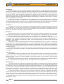
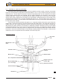
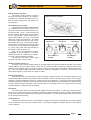
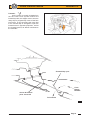
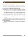
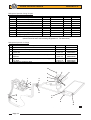
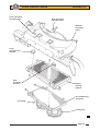
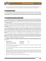
Lotus Service Notes
Section PL
AIR CONDITIONING, HEATING & VENTILATION
SECTION PL
Sub-Section Page
General Description
PL.1
3
Controls Operation & Airflow Distribution
PL.2
5
Cooling Fans & Re-circulation Pump
PL.3
11
Refrigerant Handling
PL.4
13
Refrigerant Pipework Precautions
PL.5
13
Refrigerant Oil
PL.6
15
Compressor
PL.7
16
Condenser
PL.8
18
Receiver-Drier
PL.9
20
Expansion Valve
PL.10
20
Heater/Evaporator/Fan Unit
PL.11
21
Air Distribution Unit
PL.12
22
Refrigerant Pipes
PL.13
23
Air Blender & Re-circ. Flap Actuators
PL.14
23
Page 1
Lotus Service Notes
Section PL
Heater Circuit
Water feed pipe along outside
of RH chassis siderail
Heater
matrix
Water return pipe
along outside of
LH chassis siderail
Water return to
engine side of
thermostat
p77c
Coolant re-circulation pump
Refrigerant Circuit
Receiver-drier
Feed & return pipes
along outside of RH
chassis siderail
Condenser
Expansion valve
Compressor
Evaporator casing
p78c
Page 2
Lotus Service Notes
Section PL
PL.1 - GENERAL DESCRIPTION
Heater System
The heater system uses engine coolant to provide a heat source transferred to the interior airstream via
a heat exchanger matrix mounted in an 'air blend' unit housed within the chassis well, ahead of the cabin
footwell. The coolant is fed from an outlet on the left hand side of the cylinder head, and via an alloy pipe
running along the outside of the RH chassis side rail to the matrix. Coolant is returned via a similar pipe along
the outside of the LH chassis rail to a by-pass return pipe on the left hand side of the engine.
Air temperature is controlled by a pair of air blend flaps within the heater housing which direct a varying
proportion of the airflow through, or around the matrix as determined by the position of the temperature selector knob. Note that no water valve is fitted, such that the matrix is always 'hot' when the engine is running.
Air Conditioning (If fitted) - Basic Principles
The air conditioning unit uses a cycling clutch system with a thermostatic expansion valve to provide
refrigerated air to the vehicle interior. The system comprises:
a closed circuit containing refrigerant R134a;
a compressor mounted on the front side of the engine, driven by multi-vee belt from the front end of the
crankshaft via an electromagnetic clutch;
a condenser mounted horizontally at the front of the car, beneath the engine cooling radiator;
an evaporator unit (cooler) fitted in the chassis well ahead of the cabin footwell;
a thermostatic expansion valve fitted at the inlet connection to the evaporator;
a receiver-drier unit mounted above the heater/a.c. unit
Closed Circuit
The closed refrigerant circuit should not be opened unless absolutely necessary, and only then using
appropriate refrigerant recovery equipment. Never allow the refrigerant to vent to atmosphere. Refer to subsection PL.5. Failure to observe these precautions may result in personal injury.
Expansion
valve
Trinary switch
Service ports
Condenser
Compressor
connections
Receiver-drier
High pressure
relief valve
Sill pipes
p75c
Page 3
Lotus Service Notes
Section PL
Compressor
When the engine is running, and the refrigeration controls demand it, the electromagnetic clutch incorporated in the compressor pulley is energised, which then locks the pulley to the shaft and drives the compressor.
The rotary vane type compressor operates to discharge refrigerant vapour at high pressure and temperature
into the condenser. The compressor is lubricated by a quantity of special refrigerant oil, most of which is
retained in the compressor, with the remainder being circulated with the refrigerant. An integral thermal cut-out
switch is designed to prevent overheating damage by interrupting the compressor clutch circuit if an excessively high temperature is detected.
A thermostat, sensing the temperature of the refrigerated air as it leaves the evaporator, signals the
compressor to cycle on and off. In order to avoid engine stalling and to maintain idle speed when the compressor driving load is placed on the engine, the a.c. request and compressor command signals are processed by
the engine management ECU, which amends the idle air control valve position as necessary.
Condenser
The aluminium condenser is horizontally mounted beneath the engine cooling radiator, and is of parallel
flow construction. The hot vapour received by the condenser from the compressor, releases heat to the
surrounding air via the condenser finning, with airflow boosted by two electric fans mounted below the condenser, and ram air flow caused by vehicle movement.
Evaporator
The evaporator is a tube and fin type heat exchanger mounted in a plastic housing fitted into the chassis
well ahead of the passenger compartment footwell. All incoming airflow is directed through the evaporator,
before being directed through or past the heater matrix, and then into the air distribution chamber.
The low pressure liquid refrigerant flowing into the evaporator via the expansion valve, begins to boil
(evaporate) and in so doing, draws the necessary heat for this process from the airstream passing through the
evaporator. This airstream is consequently cooled, and is directed through the various outlet vents to the
passenger compartment.
When the a.c. switch is pressed by the driver, and other parameters allow it (i.e. ignition on, blower fan
speed selected, a.c. pressure switch closed), the a.c. circuit is activated and the compressor clutch is engaged.
A thermostat, using a sensor inserted into the outlet side of the evaporator finning, monitors the temperature of
the refrigerated air and signals the compressor to cycle on and off in order to maintain outlet air temperature
just above freezing.
The inlet and outlet pipes connect to the evaporator via the expansion valve block, into which they are
sealed using 'O' rings and a clamp plate. The inlet is supplied from the receiver-drier, and the outlet feeds the
compressor.
Expansion Valve
The expansion valve block is fitted into the high and low pressure lines at the evaporator, and provides a
restriction to the flow of high pressure liquid into the evaporator, such that the consequent pressure drop
causes a change of state from a high temperature, high pressure liquid, to a low pressure, low temperature
atomised liquid.
By sensing the temperature and pressure of refrigerant leaving the evaporator, the expansion valve is
able to modulate the flow of refrigerant into the unit to optimise the cooling performance.
Receiver-Drier
The receiver-drier unit is fitted into the refrigerant line between the condenser and evaporator expansion
valve, and houses a screen sack filled with desiccant to absorb traces of moisture and other contaminants from
the refrigerant. The unit is mounted in the chassis well above the heater/a.c. unit. A sight glass built into the
top of the receiver-drier allows a visual assessment of refrigerant charge to be made - a clear sight glass may
indicate that the system is correctly charged, or completely empty, although the latter situation is usually
accompanied by oil streaks. If refrigerant charge is low, a stream of bubbles will be visible at the sight glass.
A trinary switch fitted into the top of the receiver-drier senses the pressure of refrigerant and allows
system operation only within a pressure range of 2 to 32 bar in order to prevent system damage from too high
a pressure, or from compressor oil starvation damage caused by too low a pressure. A third switching point is
used to engage the two condenser fans at half speed at pressures over 17.5 bar (see also sub-section KH.5).
An additional safeguard is provided in the form of a high pressure relief valve in the condenser inlet pipe, which
opens at 38 - 41 bar.
Page 4
Lotus Service Notes
Section PL
PL.2 - HEATER/A.C. AIRFLOW OVERVIEW
The major units of the Heating Ventilation and Air Conditioning (HVAC) system comprise a dual intake
blower fan, an evaporator housing (with no evaporator fitted for non a.c. cars), a heater housing and an airflow
distribution unit. The fan blower unit and the combined evaporator/heater unit are mounted in the chassis
climate chamber ahead of the cabin footwells, with the airflow distribution unit mounted on the top of the
chassis scuttle area. Ambient air is collected from the radiator air intake duct via two ports in the radiator
ducting, which mate to apertures in the chassis front crossmember. Moulded ducting on the rear side of the
chassis front face directs this air, via a shut off butterfly flap valve on a.c. cars (to provide a recirc. function), to
the blower fan front intake. The rear intake of the double sided fan housing is connected to perforated ports in
the front wall of each footwell.
The fan blower unit directs all airflow through the a.c. evaporator (if fitted), after which a pair of linked air
blender flaps, control the proportion of air which flows through the heater matrix. The upper flap is driven by a
stepper motor from the cockpit temperature selector, with the lower flap linked to the upper by toothed belt.
After leaving the HVAC chamber, air is ducted to a distribution chamber mounted on the top of the chassis
scuttle which distributes air to screen, face level vents and footwell vents. The distribution chamber contains
a horizontal, three vane, rotary flap, driven by a stepper motor, and controlling outlets to the screen and face
level vents. A link rod connects this flap to a second flap controlling airflow to the footwells. Ducting for the
windscreen vents is incorporated into the underside of the fascia top panel.
Schematic Airflow
Face level
vent
Windscreen
vent
Footwell vent
Re-circ. ports in
footwell
Blower fan
Heater matrix
A.C. evaporator
Re-circuation flap
(a.c. cars only)
Stepper motor for
re-circ. flap
Chassis front wall
Crash structure
Fresh air in
p101
Page 5
Lotus Service Notes
Section PL
Airflow through a.c./heater unit
Cold air
Trunking to
distribution unit
Ambient or re-circulated
air inlet
p110b
Heater
matrix
Fan blower
a.c. evaporator (if fitted)
Warm air
Flap in full
warm position
p110a
Butterfly flap open
Page 6
Lotus Service Notes
Interior Climate Controls
The interior climate controls consist of
two push switches (if fitted) for air conditioning and air re-circulation, and three rotary controls for heater temperature, fan speed, and
air distribution.
Air Conditioning (if fitted)
The left hand push button switch requests
air conditioning, but the engine must be running and a fan speed selected before the system will operate. The a.c. switch receives its
feed from the fan speed switch and energises
the a.c. request relay. When closed, the request relay supplies, via the a.c. thermostat
and trinary switch, an ECM input. The ECM
processes a valid request input, and if other
parameters allow (e.g. not wide open throttle,
not excessive coolant temperature), the ECM
will open the IAC valve before energising the
a.c. clutch relay. Note also that ambient air
temperature must be above 3°C.
With a fully cold temperature setting,
refrigerated air will be supplied. For dehumidified air, select air conditioning in conjunction with a warm temperature setting.
The tell tale in the switch button lights
up green when the circuit is active.
Section PL
INTERIOR CLIMATE CONTROLS
p98b
Temperature
Air conditioning
(if fitted)
Fan Speed
Distribution
Re-circulation
(if fitted)
p99
Air Re-circulation (with a.c.)
Air supply for the interior climate system is normally drawn from both the intake duct ahead of the engine
cooling radiator, and the vehicle interior. When the re-circulation button is pressed, a stepper motor is activated to close a butterfly flap in the fresh air intake, in order to provide a 90% recirculation supply to the blower
fan. The re-circulation facility should be used when maximum refrigeration is desired. The tell tale in the
switch button lights up green when the circuit is active.
Heater Temperature
With the left hand rotary electrical control turned fully counterclockwise, the air blender flaps are positioned to direct all the airflow to by-pass the heater chamber so that no air heating is provided. If air cooling is
required, use this temperature position in conjunction with air conditioning. Turning the control progressively
clockwise operates the stepper motor attached to the upper flap spindle, and via toothed belt to the lower flap,
to direct airflow through the heater matrix and provide an increasing level of air heating until at the fully
clockwise position, maximum heat is supplied.
Fan Speed
The centre rotary switch provides three fan speeds to boost air circulation. Turned fully counterclockwise,
the fan is off; Turning the switch progressively clockwise operates the blower fan at increasing speed in three
steps. Note that the fan operates only with the ignition switched on. The fan speed resistors are mounted in the
top of the evaporator housing.
Air Distribution
The right hand electrical rotary control operates a stepper motor on the air distribution unit to direct airflow
to the windscreen, face level and footwell vents. The following diagrams indicate airflow for the different
control positions:
Page 7
Lotus Service Notes
Section PL
Face Level):
Turned fully counterclockwise, the stepper motor on the air distribution unit (ADU)
operates the rotary flap to close off the windscreen vents, and direct all airflow to the four
face level vents, each of which may be manipulated to adjust volume and direction. The
footwell flap is closed.
Windscreen
Scuttle
baffle
panel
To face
level
vents
Air distribution unit
From
climate
chamber
Chassis scuttle
Rotary flap
Connecting link
p102a
Footwell flap closed
Page 8
Lotus Service Notes
Section PL
Footwell:
As the control is turned clockwise from
the face level vents symbol towards the
footwell symbol, the stepper motor turns the
rotary flap to progressively close off the face
level vents. A rod connecting the rotary flap
to the footwell flap is arranged to open the
footwell vents in opposite proportion, until at
the footwell symbol, all airflow is directed to
the footwells.
.
Footwell flap open
From
climate
chamber
Screen & footwell
ports closed off
To footwells
p102b
Page 9
Lotus Service Notes
Section PL
Demist:
As the control is turned clockwise from
the face level vents symbol towards the
footwell symbol, the stepper motor turns the
rotary flap to progressively open the windscreen vents. The rod connecting the rotary
flap to the footwell flap is arranged to close
the footwell vents in opposite proportion, until
at the screen symbol, all airflow is directed to
the windscreen. Select a warm temperature
setting and a suitable fan speed.
Full Defrost Performance
For maximum defrost performance, turn
the distribution knob fully clockwise and select maximum temperature and fan speed. On
cars with adjustable windscreen vents, direct
the centre pair of screen vents slightly rearwards, and the end pair of vents forwards as
shown in the illustration.
Ventilation Shut-Off
To close off the ventilation, which may
be desirable in heavy traffic to reduce the induction of fumes into the car, turn off the fan,
turn the distribution control fully
counterclockwise to the face level vent position, and manually shut off each of the face
level vents.
Inner
vent
direction
Outer
vent
direction
FULL DEFROST
PERFORMANCE
ohs98
Windscreen vent
Demist duct in
fascia top panel
Scuttle baffle panel
Windscreen port open
From
climate
chamber
Face level port closed
Footwell flap closed
p102c
Page 10
Lotus Service Notes
Section PL
PL.3 - COOLING FANS & RE-CIRCULATION PUMP
The two cooling fans are fitted beneath the radiator or (with a.c.) condenser/radiator package, and the
coolant re-circulation pump is mounted below the header tank. Both the fans and pump are controlled by the
engine management ECU using data provided by the engine coolant temperature sensor mounted in the back
of the cylinder head.
The cooling fans are switched as a pair, and will operate at half speed (connected in series) when coolant
temperature reaches 98°C on rise, and switch off at 94°C on fall. If coolant temperature rises to 103°C, the
fans will switch to full speed (connected in parallel), reverting to half speed at 98°C.
The fans will also run at half speed, unless high coolant temperature dictates otherwise, when the a.c. is
switched on and the compressor is running, or if the engine management system detects a fault with the inlet
air temperature or coolant temperature circuits.
At road speeds in excess of 85 mph (135 km/h), equating to the fan stall speed, all fan functions are
switched off.
Heat Soak
In order to help control engine temperature after switching off an engine whose temperature is over 88°C,
the ECU will remain powered for a period of 20 minutes to allow heat soak management.
A coolant re-circulation electric pump is mounted below the coolant header tank and is plumbed into the
heater supply line. When energised, the pump circulates coolant through the engine and heater system,
drawing coolant from the back of the cylinder head, and pumping it through the heater matrix to the heater
return pipe and back into the thermostat housing. The pump functions only with ignition off in conditions where
the ECU remains live. The pump is then activated at coolant temperatures over 110°C, switching off at 100°C
on fall. If temperature should rise to 115°C, the pump will be supplemented by the two cooling fans running at
half speed, switching off at 110°C on fall.
Fan Control Module
The cooling fans, re-circ. pump and a.c. compressor are controlled by a relay module mounted to the top
of the passenger side wheelarch liner. Important Note: The a.c. relay module is identical in appearance to the
engine relay module, but the function of the two modules is different and they must not be transposed. The a.c.
relay module A117M0038F has a brown label marked YWB100800; The engine relay module A111E6024F has
a white label marked YWB100970.
If the ECU receives a coolant temperature sensor signal voltage outside of the acceptable range, a
default setting equating to 60°C will be substituted, and the cooling fans activated at half speed as an engine
protection strategy.
Page 11
Lotus Service Notes
Section PL
Seat belt mouting
frame backstay
Outlet from pump to heater
Coolant
header tank
Wiring
harness
Coolant re-circulation pump
p109b
Heater return hose
Heater feed from cylinder head
Fans/compressor relay module
Shelf on driver's side
wheelarch liner
p108
Page 12
Lotus Service Notes
Section PL
PL.4 - REFRIGERANT HANDLING
The system is charged with 0.55 kg of refrigerant HFC R134a, and the following precautions MUST
ALWAYS BE OBSERVED.
1.
On no account should refrigerant ever be discharged to atmosphere - use a refrigerant recovery/recycling
station in accordance with the manufacturer's instructions. Filling points on Elise are located in the front
services compartment, and on the Exige ahead of the RH rear wheel, accessible after removal of the
wheelarch liner.
2.
Standard R134a 'quick fit' connectors are provided in the compressor suction and discharge pipes at the
right hand front of the engine bay;
- the low pressure vapour line port is fitted in the pipe between the evaporator and compressor.
- the high pressure liquid line port is fitted in the pipe between the compressor and condenser.
3.
Heavy concentrations of refrigerant vapour can produce toxic gas if exposed to a naked flame. The gas
can also attack metal.
4.
Refrigerant drums must never be left open - always ensure the caps are securely fitted.
5.
Never transport drums of refrigerant in the passenger compartment of a car.
6.
Never expose refrigerant drums to high temperature.
7.
Never weld or use a steam cleaner in close proximity to any part of the air conditioning system.
8.
Never expose the eyes to vapourised or liquid refrigerant - ALWAYS wear safety goggles and gloves
when handling refrigerant.
PL.5 - REFRIGERANT PIPEWORK PRECAUTIONS
The following precautions must be observed when carrying out any work on the refrigerant pipework:
Before disconnecting any refrigerant pipework, the refrigerant must first be recovered using suitable equipment connected to the service valves at the right hand front of the engine bay. Ensure that the equipment is
suitable for R134a.
1.
All replacement components and flexible end connections are sealed when new, and should only be
opened IMMEDIATELY PRIOR TO FITTING, AND AT ROOM TEMPERATURE, to prevent condensation
of any moisture which may enter when the sealing is removed.
2.
Pipes, flexible end connections and components, must be capped immediately they are opened to prevent the ingress of moisture and/or dirt.
3.
The receiver-drier should be the LAST component to be connected, to ensure optimum dehydration and
maximum moisture protection of the system.
4.
All joints should be coated with refrigeration oil before making any connections, to aid seating.
5.
Great care must be taken to prevent damage to the pipe fittings and connections, since due to the high
pressures involved, a leak can be caused by the slightest imperfection. Always use two spanners of the
correct size when releasing or tightening any pipe joint so that the fixed part of the union may be prevented from twisting and damaging the component. This is especially important with the aluminium
condenser.
6.
All pipes and hoses must be free from any kinking. The efficiency of the system can be impaired by a
single kink, or restriction. Flexible hoses should not be bent to a radius which is less than ten times the
diameter of the hose.
Page 13
Lotus Service Notes
Section PL
Refrigerant Pipework Fixing Torques
Key
1
2
3
4
5
6
7
8
9
10
Description
Qty
Thread
Pitch
Compressor to engine
3
M8
A.C. hoses to compressor
2
M6
Bulkhead connector, high pressure
2
3/4 - 16 UNF
1.6
Bulkhead connector, low pressure
2
1 1/16 - 14 UNS
1.8
High pressure blow off valve
1
3/8 - 24 UNF
1.1
High pressure pipe to condenser
1
3/4 - 16 UNF
1.6
Liquid line to condenser
1
5/8 - 18 UNF
1.4
Receiver-drier inlet/outlet pipes
2
5/8 - 18 UNF
1.4
Trinary switch to pipe
1
7/16 - 20 UNF
1.27
Clamp plate, pipes to expansion valve
1
M6
1
# Use refrigeration oil only, smear on "o" rings and threads prior to assembly
(Gloves should be worn when handling refrigeration oil - see data sheet)
Torque
35 Nm
10 Nm
25-30 Nm
35-40 Nm
10-13 Nm
25-30 Nm
20-25 Nm
20-25 Nm
15-20 Nm
7-9 Nm
Refrigerant Pipework 'O' Rings
Key
Description
A Suction line to compressor
B High pressure line to compressor
Suction line bulkhead connectors and expansion valve to
C
suction line
High press. line bulkhead connectors, cond. inlet, exp. valve to
D
evaporator
High pressure valve, condenser outlet, rec. drier, inlet pipe to
E
exp. valve
F Evaporator to expansion valve
Size
18mm o.d.
15 mm o.d.
Part Number
A120P6002H
A120P6001H
17mm i.d.
A082P6081F
11mm i.d.
A082P6079F
7.5mm i.d.
13.5mm i.d.
A082P6078F
A082P6080F
10
F
9
C
E
1
4
C
D
2
B
8
E
2
A
3
D
3
D
4
C
7
E
5
E
6
D
p75b
Page 14
Lotus Service Notes
Section PL
PL.6 - REFRIGERANT OIL
The internal working parts of the compressor are lubricated by refrigerant oil. This is a special type of oil
which has an affinity with the refrigerant, such that a proportion of the oil circulates with the refrigerant, around
the whole system. Under normal operating conditions, the oil never needs changing or replenishing, and if the
correct procedure for system depressurisation and re-charging is followed, minimal oil will be lost from the
system during these operations. If, however, the system suffers a major leak or sudden de-pressurisation,
most of the oil held in suspension will be lost as the refrigerant escapes, necessitating the addition of a specified quantity of oil to the compressor on re-assembly (see section PL.7).
If a refrigeration component is to be replaced, the removed item will contain a certain amount of oil, and
a corresponding amount of new oil must be added to the system on re-assembly:
Condenser;
30 cm³
Evaporator;
30 cm³
Any major pipe or hose;
10 cm³
Receiver-drier;
30 cm³
Approved Oils
Use only Denso ND-OIL 8 low viscosity (ISO46) PAG oil or equivalent (Sanden SP10; Four Seasons 59007).
Refrigerant oil absorbs water and should not be exposed to the atmosphere for any longer than is strictly
necessary to perform the operation. Never return decanted oil back into the storage container.
Page 15
Lotus Service Notes
Section PL
PL.7 - COMPRESSOR
The a.c. compressor is mounted on the left hand side of the cylinder block, beneath the alternator, and is
accessible from below.
A single multi-rib serpentine type belt is used to transmit drive from the crankshaft to the water pump,
alternator and a.c. compressor, with a slave pulley fitted in place of the power steering pump used in other
applications. A hydraulically damped, spring loaded tensioner arm applies tension to the back of the belt, and
is maintenance free. The belt itself should be inspected for condition at each service interval, and if it exhibits
any evidence of physical damage, cracking, fraying, perishing, abrasion or contamination, it should be replaced. In the case of oil or coolant contamination, the cause must be identified and rectified, and each of the
pulleys must be thoroughly degreased before the new belt is fitted.
For further details, refer to section CH in the Engine Repair Manual, but note that only a six-point socket
should be used on the cast hexagonal boss on the tensioner arm. The manufacturing draft angle on this
component may result in damage being caused by a twelve point socket.
Compressor Removal
1.
Remove the compressor drive belt by applying a six-sided socket to the cast boss on the tensioner arm
to relieve the tension, and slip the belt off the compressor pulley.
2.
Recover the refrigerant using equipment connected to the service ports at the right hand front of the
engine bay.
2.
Remove the engine bay undertray.
3.
From beneath the car, release the suction and discharge pipes from the compressor and immediately cap
the pipes and compressor ports to prevent ingress of dirt and moisture.
4.
Disconnect the compressor clutch harness.
5.
Release the three compressor fixing bolts, and remove the compressor from the engine. Retain the
compressor for oil quantity measurement if a new unit is to be fitted.
Oil Quantity Adjustment Prior to Compressor Refitment
Refitting Existing Compressor
i)
If the existing compressor is to be refitted after normal refrigerant recovery has been performed, a quantity of oil equivalent to that recovered must be added to that already held in the compressor.
ii)
If the system has suffered a rapid discharge, caused for example by accident damage, most of the
refrigerant oil will have been lost. Drain the remaining oil from the compressor by removing the drain
plug and rotating the clutch plate. Add 60 cm³ of new refrigerant oil (see above) to the compressor before
refitment.
Fitting New Compressor
New compressors are sealed and pressurised with nitrogen gas. The sealing caps should be removed
only immediately prior to compressor fitment, at which time the gas pressure should be heard to escape as a
cap is slowly released. New compressors are supplied with an oil fill of 60 cm³.
iii) If normal refrigerant recovery has been performed, the new compressor oil should be drained off, and the
required oil quantity in the new compressor calculated and added:
Drain and measure the oil quantity in the OLD compressor by removing the drain plug and rotating
the clutch plate. Quantity = X cm³
Oil quantity to be added to new compressor = X + 10 cm³
iv) If the system has suffered a rapid discharge, caused for example by accident damage, most of the
refrigerant oil will have been lost. In this case, drain the new compressor of oil and refill with 60 cm³.
Page 16
Lotus Service Notes
Section PL
Compressor Fitment
1.
Fit the compressor to the engine and secure with the three M8 bolts; Tighten to 25 Nm (18 lbf.ft). Using
a six-sided socket on the tensioner arm, fit the drive belt onto the compressor pulley.
2.
Using new 'O' rings lubricated with an approved refrigerant oil, fit the two refrigerant pipes to the compressor and tighten the fixing screws to 10 Nm (7 lbf.ft).
3.
Connect the compressor clutch harness.
4.
Recharge the system with R134a refrigerant.
Compressor
harness
connector
High pressure
outlet connection
Low pressure
suction inlet
connection
p113
Compressor fixing bolts
Page 17
Lotus Service Notes
Section PL
PL.8 - CONDENSER
The engine cooling radiator, a.c. condenser and cooling fans are secured together as a package and are
mounted horizontally, with fans lowermost, on top of the crash structure. The all aluminium condenser is of
parallel flow construction, with tanks at each side which direct the refrigerant flow from the front inlet connection successively through 10, 7, 5 and 4 rows, before it emerges from the rear outlet union. Bonded to the front
and rear of the condenser are steel channels which incorporate mounting brackets to attach the unit to the
lower flanges of the engine cooling radiator, and also to provide mountings for the two cooling fans.
For access to the condenser or cooling fans, the front clamshell must be removed followed by the radiator
mounting panel with the complete cooling pack.
1.
Remove the front clamshell (see sub-section BR.6).
2.
Remove the two air deflector/water shields.
3.
Drain the coolant and disconnect the feed and return hoses from the radiator.
4.
Unplug the fan harness connector(s).
5.
Recover the refrigerant using suitable equipment connected to the service ports at the right hand front of
the engine bay.
6.
Using two spanners on each connection to avoid twisting the union, release the two refrigerant pipes from
the condenser and immediately cap both the pipes and the condenser unions to prevent the ingress of dirt
and moisture.
Engine cooling radiator
Front spreader plate
Front mounting
bracket
a.c. condenser
Rear
mounting
bracket
Radiator
mounting
panel
Cooling fan
p106
Page 18
Lotus Service Notes
Front mounting
spreader plate
Section PL
Rear mounting
spreader plate
Radiator
mounting
panel
Front
mounting
bracket
Rear
mounting
bracket
Engine
cooling
radiator
Air conditioning
condenser
Fan fixing
Cooling fan
p105
Page 19
Lotus Service Notes
Section PL
7.
Release the radiator mounting panel from the crash structure and lift away the complete assembly.
8.
To remove the radiator pack from the mounting panel, pull out the sealing foam, release the three bolts
securing each rear bracket to the panel, and the two bolts fixing each front bracket to the panel. Separate
the fans, condenser and radiator as necessary.
9.
On re-assembly, note that the two angle brackets securing the rear of the condenser to the radiator duct,
are positioned below the condenser flange, and use a spacer washer at the adjacent fixing point to
replicate the flange thickness. Ensure that the sealing foam is refitted around the sides and rear of the
condenser, and that the spreader plates are fitted on top of the housing at the front fixing points.
10.
-
If a new condenser is fitted, add 30 cm³ of approved refrigerant oil to the system.
Use new 'O' rings on the pipe connections, and lubricate with refrigerant oil.
Using two spanners, tighten the condenser inlet connection to 25 - 30 Nm.
Using two spanners, tighten the condenser outlet connection to 20 - 25 Nm.
Recharge the system with 0.55 kg of R134a.
Refill the cooling system (see sub-section KH.3).
Radiator mounting panel
PL.9 - RECEIVER-DRIER
If the system has been open to atmosphere for any length of time, e.g. following accident damage or a burst hose or
damaged component, the receiver-drier
unit must be renewed, and should be the
last component to be fitted, and uncapped
only immediately prior to connection and
recharging.
The receiver-drier is clamped to a
mounting bracket at the front of the climate
chamber. If the receiver-drier is to be replaced, the refrigerant must first be recovered using suitable equipment connected
to the service ports at the right hand front
of the engine bay.
Cap all pipes and ports immediately
after disconnection to prevent the ingress of dirt and moisture.
When reconnecting the pipes, use
new 'O' rings coated in an approved
refrigerant oil, and tighten to 20 - 25
Nm.
Inlet connection
Trinary switch
p107
Outlet
connection
Mounting
bracket
Receiver
drier
Windscreeen
PL.10 - EXPANSION VALVE
The expansion valve is fitted onto the evaporator inlet and outlet pipes above the climate chamber, and
is accessible from within the front services compartment. To replace the valve:
1.
Recover the refrigerant using suitable equipment connected to the service ports at the right hand front of
the engine bay.
2.
Release the single M6 screw securing the clamp plate to the top of the expansion valve, and withdraw the
plate and both pipes from the valve. Immediately cap the pipes and ports to prevent the ingress of dirt
and moisture.
Page 20
Lotus Service Notes
3.
Section PL
Release the two M5 screws from the counterbored holes in the top of the valve, securing the valve to the
evaporator pipes, and withdraw the valve from the pipes. Immediately cap the pipes and ports to prevent
the ingress of dirt and moisture.
Outlet to compresser
Inlet from receiver-drier
M6 clamp screw
'O' ring seal
Top clamp plate
M5 clamp screw (x2)
Expansion valve body
Lower clamp plate
(tapped)
'O' ring seal
Evaporator outlet pipe
Evaporator inlet pipe
p71
4.
Before refitting, renew all the connector 'O' rings, and coat with an approved refrigerant oil.
5.
Fit the threaded clamp plate around the evaporator pipes, and secure the expansion valve onto the pipes
with the two M5 screws tightened to 5 - 6 Nm.
6.
Use the second clamp plate to secure the two pipes to the expansion valve, tightening the single M6
screw to 7 - 9 Nm.
7.
Recharge the system with 0.7 kg of R134a.
PL.11 - HEATER/EVAPORATOR/FAN UNIT
The heater matrix and a.c. evaporator are contained within a single housing together with the air blender
temperature control flaps. The housing is mounted in the chassis climate chamber where it is clipped to the fan
blower unit, and retained by a simple clamp bracket.
Note that the heater/a.c./blower unit is fitted the opposite way round between Rover and Toyota powertrain
cars: On 'Rover' cars, the blower unit is on the passenger side, and the air blend actuator on the rear of RHD
installations, and in front on LHD. On 'Toyota' cars, the blower is on the driver's side, and the air blend actuator
on the front of RHD cars and the rear of LHD.
Page 21
Lotus Service Notes
Section PL
To remove heater/evaporator/fan unit:
1.
Remove the front clamshell (see sub-section BR.6).
2.
3.
Remove the two air deflector/water shields, windscreen washer reservoir and ducting between heater/
a.c. unit and air distribution unit.
Recover the refrigerant using suitable equipment connected to the service ports at the right hand front of
the engine bay.
4.
Disconnect the refrigerant pipes as necessary and remove the receiver-drier unit and mounting bracket.
Disconnect the outlet pipe from the expansion valve. Cap all pipes and ports immediately to prevent the
ingress of dirt and moisture.
5.
Disconnect the hoses from the heater matrix and collect escaping coolant.
6.
Unplug the wiring harness from the temperature flap motor, a.c. thermostat and fan motor.
7.
Remove the clamping bridge retaining the unit into the chassis and release the overcentre clips securing
the unit to the fan blower housing. Withdraw the unit from the chassis together with the drain tube.
To refit heater/evaporator/fan unit:
Before refitting the unit, first ensure that the following components are fitted in the chassis:
Fresh air intake ducting/re-circulation valve assembly, retained in channel at front of chamber by single
clamp bracket. Check that re-circ. flap stepper motor harness is connected, and that the moulded plastic
water shield is fitted over the actuator.
Recirc. ducting is fitted in rear of chassis climate chamber
Earth cables are connected to chassis negative post at the left hand side of the chamber.
Rear circuit brake pipe is fitted between master cylinder and bulkhead connector.
Position the fan housing into the passenger side of the chassis chamber. Fit the drain tube into the base
of the heater/evap. unit and use a guide wire or similar to aid routing of the tube through the chassis crossmember
via the central aperture at the back of the chamber, as the unit is fitted into the chamber. Engage the lower
edges of the fan unit and heater/evap. unit before clamping together with the two overcentre latches. Retain
the assembly by fitting the bridging clamp bracket.
Continue re-assembly in reverse order to removal.
PL.12 - AIR DISTRIBUTION UNIT
The airflow distribution unit is mounted on top of the chassis scuttle, sandwiched between the underside
of the fascia top/demist duct and the chassis. The unit comprises several plastic mouldings bonded and
rivetted together to contain the rotary flap for windscreen/face level vents, and also the footwell flap. The
stepper motor for the rotary flap is mounted on the side of the unit.
To Remove
1.
Remove the front clamshell (see sub-section BR.6) and washer bottle and wiper mechanism (see subsection MP.8).
2.
Remove the air trunking between the heater/a.c. unit and the distribution unit.
3.
Release the fixings securing the heater water pipe to the chassis scuttle.
4.
Drill out the rivets securing the distribution unit retaining bracket to the chassis scuttle.
5.
Withdraw the unit from beneath the scuttle baffle panel, disconnecting the stepper motor harness plug
when access allows.
Page 22
Lotus Service Notes
6.
Section PL
Refit in reverse order to removal, ensuring that the sealing foam between the unit and baffle panel and on
the chassis scuttle is present and in good condition. Secure by re-rivetting the retaining bracket.
PL.13 - REFRIGERANT PIPES
The main feed and return (high pressure liquid and low pressure suction) lines to the compressor take the
form of aluminium pipes routed along the outside of the RH chassis rail, such that removal of the body sill panel
is required for access to the pipes. Replacement of the pipes is unlikely to be necessary other than as a result
of accident damage, in which case the body sill will be replaced in accordance with Service Notes Section BQ.
PL.14 - AIR BLENDER & RE-CIRC. FLAP ACTUATORS
The stepper motor (actuator) for the air temperature blender flap is mounted on the side of the heater/a.c.
casing and is secured by two screws. A moulded plastic cover is hooked over the actuator to provide protection
from direct water contamination. On installations where the actuator is on the rear of the unit (RHD Rover
powertrain; LHD Toyota powertrain), access to the actuator requires the unit to be removed from the chassis
(see sub-section PL.12).
With the heater/a.c. unit removed, pull off the moulded water shield and release the two fixings securing
the actuator to the casing. The nuts are accessible inside the casing via the air outlet aperture, but the air
blender flap may need to be moved to allow access to both nuts. In order to allow flap movement, the flap must
be mechanically disconnected from the motor by unclipping the actuator outer cover and sliding a drive gear
off its shaft.
On installations where the actuator is on the front of the unit (LHD Rover powertrain; RHD Toyota powertrain),
and the car is not fitted with air conditioning, the actuator is accessible with the unit 'in-situ'. Remove the front
clamshell (sub-section BR.6), release the harnesses from the the front edge of the climate chamber and tie
back the harnesses and water hoses to allow optimum access to the actuator. Pull off the moulded water
shield, unclip the actuator outer cover and slide off a drive gear to allow the flap to be moved for access to the
two fixing nuts inside the casing. To aid reassembly, it is recommended to glue the two fixing spacers in
position.
The re-circulation flap actuator on both RHD and LHD cars is accessible only with the heater/a.c. unit
removed. If this should occur, the re-circ. flap actuator water shield should be fitted (if not already present) by
withdrawing the re-circ. flap assembly from the channel in the front of the climate chamber, hooking the water
shield over the actuator and refitting into the chassis, noting that the actuator lead is looped downwards to
prevent water tracking along the lead and into the actuator.
Early cars built before May 2004 will benefit from the fitment of an extended clamshell gutter (if not
already fitted). On later cars, the fettling of the clamshell was revised to prevent water spilling directly into the
actuator area.
Parts Required
Gutter Extension Panel, RHD
Gutter Extension Panel, LHD
Part Number
A117B0703K
A117B0704K
Qty
1
1
1.
Remove both front body access panels, and the two louvre panels. Remove the two air deflector panels
to which the louvre panels attach.
2.
The rear of the radiator is secured by two pairs of screws along the top rear edge. Release the inboard
screw on each side.
3.
Before attempting to install the new gutter extension panel, protect the top surface of the radiator with a
rigid plastic sheet or similar to avoid damage to the delicate finning. Manoeuvre the gutter extension
panel into the underside of the clamshell spine, and retain with the two radiator fixing screws. Note that
the panel incorporates a hot air dam for the spine area.
4.
Refit the two air deflector panels, the louvres and the access panels.
Page 23
Lotus Service Notes
Section PL
Hot air dam
Gutter extension panel
Radiator
inboard fixing
sb79
Page 24