1
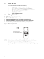
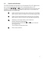
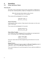
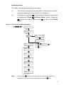
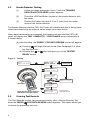
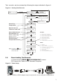
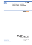
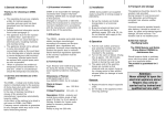
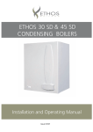
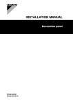
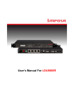
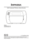
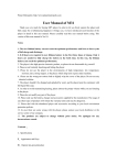
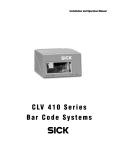
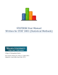
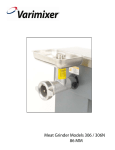
FSD-100
Smoke Detector Sensitivity Meter
User Guide
Warning: This document contains information on limitations regarding
product use and function and information on the limitations as to liability
of the manufacturer. Read the entire manually carefully.
TABLE OF CONTENTS
1
Introduction . . . . . . . . . . . . . . . . . . . . . . . . . . . . . . . .1
1.1
Out of the Box . . . . . . . . . . . . . . . . . . . . . . . . . .2
1.2
Battery Installation . . . . . . . . . . . . . . . . . . . . . . .2
1.3
Controls & Indicators . . . . . . . . . . . . . . . . . . . . .3
2
Operation . . . . . . . . . . . . . . . . . . . . . . . . . . . . . . . . . .4
2.1
Power Up / Power Down . . . . . . . . . . . . . . . . . .4
2.2
Smoke Detector Testing . . . . . . . . . . . . . . . . . . .6
2.3
Viewing Test Records. . . . . . . . . . . . . . . . . . . . .7
2.4
Downloading Test Records . . . . . . . . . . . . . . . .8
2.5
Checking Tester Status . . . . . . . . . . . . . . . . . . .9
APP A
Status & Troubles . . . . . . . . . . . . . . . . . . . . . . . . . .11
APP B
Sensitivity Measurement Conversion . . . . . . . . . .11
1
Introduction
The FSD-100 Smoke Detector Sensitivity Meter is intended for comprehensive inplace-testing of the WS-4916, FSA210 and FSA410 Series Smoke Detectors. The
meter is hand held and battery operated, providing 20 hours of continuous operation and stores up to 500 detector tests.
Features:
•
•
•
•
•
•
•
•
•
9 Volt alkaline battery provides 20 Hrs (minimum) operation
Internal battery check displays remaining battery capacity.
Battery Reverse Polarity Protection.
Automatic shutdown 4 minutes after last key press.
All features are accessed using 4 pushbuttons
Storage and retrieval of up to 500 detector tests.
Records stored in non-volatile memory
Downloads records to PC using MicroSoft® HyperTerminal® software
Records Date, Time, Model and Version, Date of Manufacture, and Serial
Number for all tests.
Detector Troubles
Smoke, low sensitivity
Smoke, high sensitivity
Smoke sensor fault
Heat sensor fault
Measurement errors
Memory errors
Trouble already transmitted
Detector Status
Tampers
Smoke Alarm
Smoke Sensor Trouble/fault
Low Battery (Smoke Detector)
Heat Alarm
Heat sensor fault
Cold temperature warning
1
1.1
Out of the Box
The FSD-100 tester includes the following:
1
1
1
1
1
1
1.2
FSD 100 Smoke Detector Sensitivity Meter
Duracell® Procell® PC1604 Alkaline 9VDC Battery
PC-Link Local Download KIT-DB09.
Download kit adaptor
User Guide
Quick Reference Guide
Battery Installation:
The FSD-100 is shipped with a battery
1.
2.
3.
4.
Remove the rear cover
Remove the battery from the battery compartment.
Remove the plastic protection from the battery terminals.
Insert battery as indicated in the battery compartment.
Figure 1 - Battery Replacement
+
-
Duracell Procell
PC1604 Alkaline 9VDC
+
-
-
NOTES: Replace battery with Duracell® Procell® PC1604 Alkaline 9VDC Battery.
Incorrect placement of the battery will NOT damage the unit.
Removal and replacement of battery will NOT delete stored records.
You will be prompted to set date and time on first power up following battery
replacement.
2
1.3
Controls and Indicators:
The FSD-100 displays all information on a 32 character LCD. A PC LINK connection is located on the right side of the unit for downloading data to a PC.
The use of the
,
,
, and
keys varies depending on the screen you are
currently in. Use of these keys is indicated on each screen. The list below indicates the general use of these keys.
Used to Scroll forward through menu selections from the Ready
Mode. Moves cursor to the right in time and date programming.
Used to Scroll back through menu selections from the Ready
Mode. Moves cursor to the left in time and date programming.
Advances to next option within a menu sequence.
Initiates Testing and Downloading.
Increments value selected with
date programming.
and
keys in time and
Turns off device during power down.
Exits a menu selection.
3
2
Operation:
2.1
Power Up/Power Down
Powering Up:
On power up the model name and version of the tester is displayed on
the top line, remaining battery capacity is displayed on the second line.
Note: 99% indicates that the battery is fully charged.
Replace battery when 1% is indicated.
This screen will be displayed for 2 seconds.
FSD-100 V1.00
BATTERY LIFE=99%
Record Capacity:
Indicates the current number of tests stored in the tester out of a maximum of 500 tests.
This screen will be displayed for 2 seconds.
RECORD CAPACITY:
300/500 FILLED
Time & Date Trouble:
This screen will only be displayed if time and date are unprogrammed
(e.g., at first power up or after battery replacement).
TIME & DATE TRBL
PRESS * TO PROG.
Press # to save date and time programming and advance to the next
screen.
Ready Screen:
This screen is displayed 2 seconds after the Record Capacity screen is
displayed or after exiting Date and Time programming.
This screen allows you to scroll through the 6 menu options available on
the tester.
4
Powering Down:
The tester can be powered down in two ways:
(1)
The unit will automatically power down 4 minutes after the last
keypress regardless of the screen it is currently in.
(2)
Pressing the scroll key
5 times from the Ready mode screen
will display the "Press
for Power Down" screen. Press the
key twice to power down or press
screen.
to return to the Ready
Figure 2 - Power Up and Main Flow Menu
Press
or
key
for 2 seconds to Power up
FSD-100 V1.00
BATTERY LIFE=99%
2 Second
Delay
RECORD CAPACITY:
300/500 FILLED
2 Second
Delay
Time & Date
Set ?
No
TIME & DATE TRBL
PRESS * TO PROG.
Yes
* =INC #=EXIT <>
HH:MM YYYY/MM/DD
READY
<>
SCROLL FOR MENUS
Press or to move cursor
(sequence indicated is for the
Press
to increment value
Press
to exit
key)
PRESS * FOR
<>
DEVICE READING
PRESS * FOR
<>
DEVICE RECORDS
PRESS * FOR
PC DOWNLOAD
<>
PRESS * FOR
TESTER INFO
<>
PRESS # FOR
<>
TIME/DATE PROG.
PRESS * FOR
POWER DOWN
Note:
Pressing the
<>
key will scroll through the menu in the sequence
indicated. To scroll in the reverse direction use the
key.
5
2.2
Smoke Detector Testing
(1)
Follow the steps indicated in figure 3 until the TRIGGER
DEVICE WAIT FOR BEEP screen appears.
(2)
Press the LED/Test Button located on the smoke detector with
the tester.
(3)
Position the tester less than 2.5 cm (1 Inch) from the center
dome of the smoke detector.
The Smoke Detector and the FSD-100 Tester will indicate that data is being transmitted and received by sounding a series beeps from each device.
When data transmission is completed, the beeping will stop and the FSD-100
tester will display the TEST COMPLETE ! DATA SAVED screen followed by a
2 second delay.
(4) After the delay the PRESS * FOR DATA REVIEW screen will appear.
(a) Pressing
will begin the test review (See Paragragh) 2.3 Viewing Test Records.
(b) Pressing the
or
READY screen.
keys will return you to the TESTER
Figure 3 - Testing
READY
<>
SCROLL FOR MENUS
PRESS * FOR
<>
DEVICE READING
To next
menu item
TESTER READY
* =READ # =EXIT
TRIGGER DEVICE
WAIT FOR BEEP
Signal ?
Yes
No
1 Minute
Window
ERROR NO SIGNAL
PRESS # TO EXIT
LED/Test Button
TEST COMPLETE !
DATA SAVED
2 Second
Delay
Position Tester less than 2.5cm (1 inch) from
Smoke Detector in the position indicated
2.3
PRESS * FOR
DATA REVIEW
<>
See Paragraph 2.3
Viewing Data Records
Viewing Test Records
The Test Records section can be entered directly after a Smoke Detector Test
when the PRESS
FOR DATA REVIEW screen appears. This option allows you
to review the preceding test only.
6
Test records can be reviewed by following the steps indicated in figure 4.
Figure 4 - Viewing Test Records
PRESS * FOR
<>
DEVICE RECORDS
READY
<>
SCROLL FOR MENUS
PRESS * FOR
<>
RECORD: XXX/500
Records
Available
?
Yes
Sensitivity
No
Model & Version
of device under Test
WS4916 ULC
VERSION: 1.00
BUFFER EMPTY
PRESS # TO EXIT
*
Date of Manufacture
Serial Number of
device under Test
Battery Level
(Device Power)
DOM:YYYY/MM/DD *
SERIAL #: 4XXXX
BATTERY LIFE=99%
COMP:+XXX%=NORM
Compensation Level
TRBL: 12345678 *
STAT: 12345678
RECORD TIME/DATE
YYYY/MM/DD HH:MM
key at
anytime will return you
to the main flow.
2.4
PRESS * FOR
<>
RECORD: XXX/500
SENS: 2.5%/FT *
TEMP: 25°C 77°F
Temperature
Note: Pressing the
To next
menu item
PRESS # FOR
<>
PREVIOUS MENU
Troubles:
1 = Smoke Low Sensitivity
2 = Smoke High Sensitivity
3 = Smoke Sensor Test Failed
4 = Smoke Sensor Fault
5-= Heat Sensor Fault
6 = Measurement Errors
7 = Memory Error
8 = Trouble Already Transmitted
Status:
1 = Tamper
2 = Smoke Alarm
3 = Smoke Sensor Trouble/Fault
4 = Low Battery (Smoke Detector)
5 = Smoke Early Warning
6 = Heat Alarm
7 = Heat Sensor Fault
8 = Cold Temperature Warning
Downloading Test Records
(1) Scroll to the "PRESS
FOR DOWNLOAD" screen.
(2) Connect the Tester to the Personal Computer.
Figure 5 - Tester Setup
NOTE: A DB09 to DB25 adaptor may be required for some computer configurations
7
(3) Open Microsoft® HyperTerminal® or equivalent.
Configure the Serial COM Port as follws:
Set Baud Rate to 9600
Set Bits to 8
Set Parity to None
Set Stop Bits to 1
(4) Press
to initiate downloading.
(5) When downloading is complete, a beep will be sounded and you will
be prompted to delete the tester records.
(6) Save File - The saved file can be exported to another program such
as Microsoft® Excel®. See Program User Manual or Help File.
Figure 6 - Downloading
READY
<>
SCROLL FOR MENUS
PRESS * FOR
PC DOWNLOAD
<>
CONNECT PC CABLE
PRESS * TO SEND
DOWNLOADING DATA
PLEASE WAIT
DOWNLOAD
COMPLETE!
<>
DELETE ALL
<>
RECORDS? *=Y #=N
ARE YOU SURE?
* = Y # = N
DELETING RECORDS
PLEASE WAIT
DEVICE RECORDS<>
XXX/500 FILLED
PRESS # FOR
<>
PREVIOUS MENU
8
To Next Menu
Item
2.5
Checking Tester Status
Battery life, number of records stored, date & time programming and powering
down can all be accessed from this screen.
Figure 7 - Checking Tester Status
READY
<>
SCROLL FOR MENUS
PRESS * FOR
TESTER INFO
<>
PRESS # FOR
<>
TIME/DATE PROG.
PRESS * FOR
POWER DOWN
BATT LIFE= 99%<>
RECORDS: XXX/500
* =INC #=SAVE <>
12:00 2003/01/01
POWER DOWN ?
* = YES # = EXIT
2 Second
Delay
Time & Date
Set ?
No
TIME & DATE TRBL
PRESS * TO PROG.
<>
Note: Tester will automatically
power down 4 minutes
after the last keypress
Yes
* =INC #=EXIT <>
HH:MM YYYY/MM/DD
PRESS # FOR
<>
PREVIOUS MENU
Press
or
Press
to increment value
to move cursor
Press
to exit
9
NOTES:
Appendix A: Status and Troubles
The following table lists the Troubles
and Status Readings found in the
Trouble Status screen
TRBL: 12345678 *
STAT: 12345678
Troubles
Status
1
Smoke Low Sensitivity
1
Tamper
2
Smoke High Sensitivity
2
For Factory Use
3
Smoke Sensor Test Failed
3
Smoke Sensor Trouble/Fault
4
Smoke Sensor Fault
4
Low Battery
5
Heat Sensor Fault
5
Smoke Early Warning
6
Measurement Errors
6
For Factory Use
7
Memory Error
7
Heat Sensor
8
Trouble Already Transmitted
8
Cold Temperature Warning
Appendix B: Sensitivity Measurement Conversion
The following table converts sensitivity measurements in % obscuration per foot
(NA) to the approximate measurement in dBm (EU)
Sensitivity %/ft
0.25
0.50
0.75
1.00
1.25
1.50
1.75
2.00
2.25
2.50
2.75
3.00
3.25
3.50
3.75
4.00
4.25
4.50
4.75
5.00
Sensitivity dBm
0.036
0.071
0.107
0.143
0.179
0.215
0.252
0.288
0.324
0.361
0.397
0.434
0.471
0.508
0.545
0.582
0.619
0.656
0.693
0.731
11
Limited Warranty
Digital Security Controls Ltd. warrants that for a period of twelve months from the date of purchase, the product shall be free of defects
in materials and workmanship under normal use and that in fulfillment of any breach of such warranty, Digital Security Controls Ltd.
shall, at its option, repair or replace the defective equipment upon return of the equipment to its repair depot. This warranty applies only
to defects in parts and workmanship and not to damage incurred in shipping or handling, or damage due to causes beyond the control of
Digital Security Controls Ltd. such as lightning, excessive voltage, mechanical shock, water damage, or damage arising out of abuse,
alteration or improper application of the equipment.
The foregoing warranty shall apply only to the original buyer, and is and shall be in lieu of any and all other warranties, whether
expressed or implied and of all other obligations or liabilities on the part of Digital Security Controls Ltd. Digital Security Controls Ltd.
neither assumes, responsibility nor authorizes any other person purporting to act on its behalf to modify or to change this warranty, nor
to assume for it any other warranty or liability concerning this product.
In no event shall Digital Security Controls Ltd. be liable for any direct, indirect or consequential damages, loss of anticipated profits,
loss of time or any other losses incurred by the buyer in connection with the purchase, installation or operation or failure of this product.
Smoke Detectors
Smoke detectors that are a part of this system may not properly alert occupants of a fire for a number of reasons, some of which follow.
The smoke detectors may have been improperly installed or positioned. Smoke may not be able to reach the smoke detectors, such as
when the fire is in a chimney, walls or roofs, or on the other side of closed doors. Smoke detectors may not detect smoke from fires on
another level of the residence or building.
Every fire is different in the amount of smoke produced and the rate of burning. Smoke detectors cannot sense all types of fires equally
well. Smoke detectors may not provide timely warning of fires caused by carelessness or safety hazards such as smoking in bed, violent
explosions, escaping gas, improper storage of flammable materials, overloaded electrical circuits, children playing with matches or
arson.
Even if the smoke detector operates as intended, there may be circumstances when there is insufficient warning to allow all occupants to
escape in time to avoid injury or death.
Warning: Digital Security Controls Ltd. recommends that the entire system be completely tested on a regular basis. However, despite
frequent testing, and due to, but not limited to, criminal tampering or electrical disruption, it is possible for this product to fail to
perform as expected.
Important Information: Changes or modifications not expressly approved by Digital Security Controls Ltd. could void the user’s
authority to operate this equipment.
FCC Compliance Statement
CAUTION: Changes or modifications not expressly approved by DSC could void your authority to use this equipment.
This equipment has been tested and found to comply with the limits for a Class B digital device, pursuant to Part 15 of the FCC
Rules. These limits are designed to provide reasonable protection against harmful interference in a residential installation. This
equipment generates, uses and can radiate radio frequency energy and, if not installed and used in accordance with the instructions, may cause harmful interference to radio communications. However, there is no guarantee that interference will not occur
in a particular installation. If this equipment does cause harmful interference to radio or television reception, which can be
determined by turning the equipment off and on, the user is encouraged to try to correct the interference by one or more of the
following measures:
• Re-orient the receiving antenna.
• Increase the separation between the equipment and receiver.
• Connect the equipment into an outlet on a circuit different from that to which the receiver is connected.
• Consult the dealer or an experienced radio/television technician for help.
The user may find the following booklet prepared by the FCC useful: “How to Identify and Resolve Radio/Television Interference Problems”. This booklet is available from the U.S. Government Printing Office, Washington D.C. 20402, Stock # 004-00000345-4.
Industry Canada Compliance Statement
This Class B digital apparatus meets all requirements of the Canadian interference-causing equipment regulations.
Cet appareil numérique de la Classe B respecte toutes les exigences de règlement sur le matériel brouilleur du Canada.
©2003 Digital Security Controls
Toronto • Canada • 1-800-387-3630
www.dsc.com Printed in Canada
Forward comments about this manual to:
[email protected]•
29 03466 6R001