1
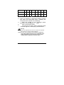
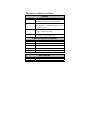
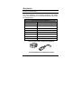
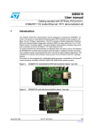
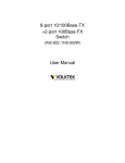
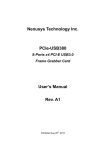
10/100Base-TX to 100Base-FX Industrial Converter (IRF-620) User’s Guide COPYRIGHT All rights reserved. No part of this publication may be reproduced, stored in a retrieval system, or transmitted in any form or by any means, whether electronic, mechanical, photo copying, recording or otherwise, without the prior written permission of the publisher. FCC WARNING This equipment has been tested and found to comply with the limits for class A device, pursuant to part 15 of FCC rules. These limits are designed to provide reasonable protection against harmful interference in a commercial installation. This equipment generates, uses and can radiate radio frequency energy and, if not installed and used in accordance with the instructions, may cause harmful interference to radio communication. Operation of this equipment in a residential area is likely to cause harmful interference, in which case, the user will be required to correct the interference at the user’s own expense. CE This is a Class A product. In a domestic environment, this product may cause radio interference in which case the user may be required to take adequate measures. Take special note to read and understand all content giving in the warning boxes Warning TABLE OF C ONTENTS ABOUT THIS GUIDE............................................................ 4 TERMS/USAGE ....................................................................... 4 INTRODUCTION ................................................................... 5 FEATURES .............................................................................. 5 IRF-620 INDUSTRIAL CONVERTER UNPACKING AND SETUP .................................................................................... 6 UNPACKING ........................................................................... 6 LAYOUT OF THE IRF-620....................................................... 7 DIN RAIL MOUNTING OF THE IRF-620.................................. 9 GROUNDING IRF-620 .......................................................... 10 REDUNDANT POWER INPUTS ................................................ 11 CONFIGURING DC POWER INPUTS ........................................ 11 ETHERNET CONNECTIONS .................................................... 13 FIBER CONNECTIONS ........................................................... 14 LED INDICATORS ................................................................ 15 EXTERNAL ALARM CONTACT .............................................. 16 DIP SWITCH SETTINGS ........................................................ 17 AUTO-NEGOTIATION (NWAY) ............................................. 18 NWAY DIP SWITCH SETTING .............................................. 18 LINK FAULT SIGNALING (LFS) ............................................ 20 LOOPBACK TESTING (REMOTE & LOCAL)............................ 21 TECHNICAL SPECIFICATIONS ...................................... 24 APPENDIX ........................................................................... 26 A BOUT T HIS G UIDE The IRF-620 Industrial Series (10/100Base-TX to 100Base-FX) Converter is a hardened with redundant DC power inputs to provide a reliable and economical solution for your industrial Ethernet environment. With its dry contact smart alarm, the IRF-620 issues an alarm function on the factory floor in the event of any malfunction. The IRF-620 has a wide operating temperature range from 0 to 70°C, and is designed to sustain higher than normal degrees of vibration and shock, making is suitable and safe for harsh industrial environments. This guide discusses how to install the IRF-620 Industrial Series Converter. Terms/Usage In this guide, the term “Converter” (first letter upper case) refers to the IRF-620 Industrial Fast Ethernet Converter, and ”converter” (first letter lower case) generically refers to all other Ethernet converters. 4 I NTRODUCTION This chapter describes the features and specification of the Converter. Features • • • • • • • • • • • • • Automatic MDI/MDI-X selection on RJ-45 port Link Fault Signaling (LFS) Store-and -forward at full wire speed Auto-negotiation, NWay support Half/Full duplex mode selection Remote and local loopback Test via DIP switch When DIP switches are set, the system auto-reboots to new configurations without powering-off. Extends distance of up to 2km (6600 feet) multimode fiber and 120km (396000 feet) long-haul single mode fiber Compatible with other 10Base-T & 100Base-TX /FX devices LEDs for at-a-glance device status Suitable for industrial harsh environment Wide voltage range (9 ~ 48V DC) with primary & redundant power inputs FCC Class A & CE approved 5 IRF-620 I NDUSTRIAL C ONVERTER U NPACKING AND S ETUP This section and the following sections explain the setup and installation of the VOLKTEK IRF-620 Industrial Converter. Unpacking Open the box of the Converter and carefully unpack it. The box should contain the following items: 9 One IRF-620 (10/100Base-TX to 100Base-FX) Fast Ethernet Converter 9 One DIN rail bracket 9 Protective caps for unused ports Quick Installation Guide This User’s Guide CD 9 9 If any item is found missing or damaged, please contact your local reseller for replacement. 6 Layout of the IRF-620 Front View of Converter 2 3 1 4 5 1. 2. 3. 4. 5. 6 6. 7 7. 8. 9. 8 9 7 Alarm LED Redundant Power LED Primary Power LED 100Base-FX port Fiber & Copper ports LNK/ACT LEDs x 2 (1 LED for each port) Fiber & Copper ports FDX/COL x 2 (1 LED for each port) LFS LED 100Mbps LED for copper port Copper port TOP View of Converter Grounding Screw Terminal block for power input (PWR/RPS), and alarm dry contact DIP Switches Back View of Converter Din Rail Bracket Screws 8 DIN Rail Mounting of the IRF-620 The aluminum DIN Rail attachment plate should already be affixed to the back panel of the Converter. If you need to attach the DIN Rail plate, assure that the stiff metal spring is situated towards the top. Attaching the Converter to the DIN rail is easy, just align, and attach the top rail, then press down and snap forward the Converter to snap in the bottom rail, as shown in the figures below. The setup of the Converter can be performed using the following steps: • • • The surface must support at least 1.00 Kg for the Converter. The power outlet should be within 1.82 meters (6 feet) of the Converter. Visually inspect the DC power jack and make sure that it is fully secured to the power adapter. 9 • Make sure that there is proper heat dissipation from and adequate ventilation around the Converter. Do not place heavy objects on the Converter. Grounding IRF-620 Be sure to disconnect the power cord before installing and/or wiring your IRF-620 Industrial Converter. Calculate the maximum possible current in each power wire and common wire. Observe all electrical codes dictating the maximum current allowable for each wire size. If the current goes above the maximum ratings, the wiring could overheat and causing serious damage to your equipment. Users must pay attention to the following items. Use separate paths to route wiring for power and devices. If power wiring and device wiring paths must cross, make sure the wires are perpendicular at the intersection point. Do not run signal or communications wiring and power wiring in the same wire conduit. To avoid interference, wires with different signal characteristics should be routed separately. User can use the type of signal transmitted through a wire to determine which wires should be kept separate. The rule of thumb is that wiring that 10 shares similar electrical characteristics can be bundled together. Keep input and output wiring separated. It is strongly recommended that you label wiring to all devices in the system for clarity. Grounding IRF-620 Industrial Converter will help eliminate the effects of noise due to electromagnetic interference (EMI). Always run the ground connection from the ground screw to the grounding surface prior to connecting DC power. This product is intended to be mounted to a well-grounded mounting surface. Redundant Power Inputs Redundant Power Inputs: Both power inputs can be connected simultaneously to live DC power sources. If one power source fails, the other live source acts as a backup, and automatically supplies the Converter’s power needs. Configuring DC power Inputs Configuring DC power to the Terminal Block Receptor 11 DC Powered Switch: Power is supplied through an external DC power source. Check the technical specification section for information about the DC power input voltage. Since the Converter does not include a power switch, plugging its power adapter into a power outlet will immediately power it on. The plastic green colored contact power block (shown in the diagram to the left) is composed of six contacts and can be inserted and removed easily by hand to connect to the six pin terminal block receptor (male contacts located on the body of the Switch). The top two contacts (PWR) are designated for the primary DC input, while the middle two contacts (RPS) are for redundant DC input. The lower two contacts (ALM) are for connection to an external alarm. To the upper right of the power block is the ground wire connection screw, and below the power block is the DIP switch control panel. 12 Procedure for Configuring DC Power: During shipping, the removable green Contact Block may already be detached from the six pin terminal contact point. It may be easier to attach the DC wires to the green Contact Block if it has first been unplugged from the terminal contact point on the Converter. A. On the Power Contact Block, use a flathead screwdriver to loosen the screws reserved for primary power (labeled PWR +/-) and then insert negative and positive DC wires. Tighten until snug. B. For the backup DC connection, follow the same procedure as above. Attach DC power wires to the Contact Block (in the position marked RPS +/-) C. If not already inserted into the terminal block receptor into the Converter, do so now. D. Assure your DC power supply is stable and clean before applying DC power to the Converter. Ethernet Connections The IRF-620 Industrial Fast Ethernet Converter has one 10/100Base-TX Ethernet port, and one 100 Base-FX LC type connector fiber port. 13 The ports are located on the Converter’s front panel and are used to connect to Ethernet-enabled devices. Fiber Connections When connecting fiber cable to the Converter, be sure the correct type – ST or SC - connector is used. Follow the steps below to properly connect fiber cable: 1. Remove and keep the ST/SC port rubber covers. When not connected to a fiber cable, the rubber cover should be replaced to protect the optics. 2. Check that the fiber terminators are clean. You can clean the cable plugs by wiping them gently with a clean tissue or cotton ball moistened with a little ethanol. Dirty fiber terminators on fiber optic cables will impair the quality of the light transmitted through the cable and lead to degraded performance on the port. 3. Connect one end of the cable to the ST/SC port on the Converter and the other end to the ST/SC port on the other device. 4. Check the corresponding port LED on the Converter to be sure that the connection is valid. (Refer to the LED chart) Warning Because invisible laser radiation may be emitted from the aperture of the port when no cable is connected, avoid exposure to laser radiation and do not stare into open apertures. 14 LED Indicators Unit LEDs The Converter has following nine LEDs. Power Indicator (PWR): This LED lights green when the Converter is receiving power from primary input. Redundant Power Supply (RPS): This indicator lights green when the Converter is receiving power from redundant input. Alarm (ALM) This indicator will light red and will signal an alarm (when an external alarm is connected) during a down link condition on any port and during primary power failure to the Converter. FDX/COL LEDs 2 x LEDs (amber) to indicate FDX/COL status (1 x LED for each port), illuminates to indicate Full Duplex mode, and flashes to indicate Collision. LNK/ACT LEDs 2 x LEDs (green) to indicate LNK/ACT status (1 x LED for each port), illuminates to indicate receiving link pulses from a compliant device, and flashes to indicate data packets being sent/received. 100 The LED will illuminate green during 100Mbps link, 15 otherwise; the LED’s will be off. LFS Illuminates red when a break or disruption exists in copper or fiber links. External Alarm Contact The IRF-620 Industrial Converter has one Alarm Contact located on the green Power Block Contact on the top panel. For detailed instructions on how to connect the Alarm Contact power wires to the two lower contacts of the 6-contact terminal block connector, see the Connecting DC Power inputs in the section above (it is the same procedure). You can connect the Fault circuit to any warning light which the user’s factory or industry already has located in the control room or factory floor. When a fault occurs, the Converter will send a signal through the Alarm contact, to activate the external alarm or siren. The Alarm Contact has two terminals that form a Fault circuit for connecting to an alarm system. An alarm will be signaled in the following situations: 1. Any link fail (ex: cable disconnected, device break down .....) 2. PWR/RPS: Power failure 16 a. Power cord is disconnected, power supply malfunction, etc. b. Input power is out of the range listed in the spec (9~ 48V) DIP Switch Settings DIP Switches allow for the user to manually enable/disable external alarm, Nway, duplex mode, and loopback functions. The figure below shows the DIP switch control. DIP 1 (PWR) Enable/Disable the primary power input external alarm. Default is OFF (Disable). DIP 2 (RPS) Enable/Disable the redundant power input external alarm. Default is OFF (Disable). DIP 3 (LFS) Enable/Disable the Link Fault Signaling (LFS) external alarm. Default is OFF (Disable). DIP 4 (NWay) Enable/Disable the NWay function. Default is ON (Enable). DIP 5 (Data bit rate) On: 10Mbps Off: 100Mbps. Default is OFF (100Mbps). Note: Copper port only. DIP 6 (Duplex mode) On: Half Off: Full. Default is OFF (Full duplex). Note: Copper port only. 17 DIP 7 (LLB) Default is OFF. Manually move the switch to ON to perform the Local Loopback test. DIP 8 (RLB) Default is OFF. Manually move the switch to ON to perform the Remote Loopback test. Auto-negotiation (NWay) The IRF-620 Industrial Converter’s 10/100 Mbps RJ-45 port auto negotiates with the connected device for the fastest data transmission rate supported by both devices. This helps make the Converter plug-and-play device. The half/full duplex mode for the RJ-45 ports are user dependent and changes (by auto-negotiation) to full or half duplex, depending on which transmission speed is supported by the attached device. NWay DIP Switch Setting Use the NWay DIP switch to activate NWay operations. Factory NWay DIP switch default set to ON position. Check that the networking device to be connected to the Converter has NWay support. If YES: Check that the NWay DIP switch is set to the ON position. The Converter will automatically set the optimum speed and duplex mode on the copper segment. Users can skip the settings for DIP switches 5 and 6, when NWay is activated. 18 If NO: Set the NWay DIP switch to the OFF position. Then Use DIP switch 6 to manually select between half (HD) and full duplex (FD) modes. Use DIP switch 5 to manually select between 10Mbps or 100Mbps speeds. Set NWay switch to OFF position when connecting to an auto-sensing device that only supports 10/100Mbps detection. Some early models only support auto-sensing of speed, and NOT auto detection of speed and duplex mode (auto-negotiation). Important In order to configure DIP switches 6 (duplex mode) and 5 (speed), you must set DIP switch 4 (NWay) to the OFF position Setting the duplex mode is feasible while the media converter is “on-line” Note: If you experience the following problems, please check if the NWay switch is properly set. 1. The LNK (link) LED is not lit and the connection cannot be established 2. The LNK LED is lit and the connection is ok, but cannot transmit or receive data 3. The converter functions properly for a while, then, it does not work. And then it works after powering off and then on again. 19 Link Fault Signaling (LFS) LFS is a “nice to have” function that is extremely beneficial in terms of network status monitoring. The LFS LED will immediately light to indicate when a cable has been severed or when some other cause of disruption in service has occurred. The LFS function monitors both copper and fiber segments giving a total connection status report. Set LFS to ON position for normal operational use. Set LFS to OFF (default) position when installing cables or when testing the network connection. Note: The LFS feature influences both fiber and copper segments. Therefore, when disruption occurs on either segment, the LFS feature will be activated and the LED will light to indicate that the entire connection is down. To appreciate the full benefits of LFS, four converters can be used to build a primary and a secondary link. They must be connected to a switch that supports Spanning Tree or Fast Spanning Tree protocols. By default, transmission of data will travel via the primary link. Once a fault has been detected, transmission will automatically be switched to the secondary link, resulting in ‘non-stop’ network connectivity. 20 Loopback Testing (Remote & Local) This Converter features DIP switches to activate both local and remote loopback diagnostic test functions. Use local loop back to check if the copper segment is connected properly, and use remote loop back to check if the fiber segment is connected properly. Please see Diagram below: Dip Switch 7 ON: enables local loop back function OFF: disables local loop back function Dip Switch 8 ON: enables remote loop back function OFF: disables remote loop back function Make sure that the cables are connected properly before getting started. Conduct either the local or remote test, not both at the same time. Follow the steps below to perform the diagnostic tests. Local Loopback 1. Test Condition setup – for the function to produce an accurate result, be sure to set DIP switches according to 21 the table below: DIP Switches 1 2 3 4 5 6 7 8 Converter A ON ON ON OFF OFF OFF ON OFF Converter B ON ON ON OFF OFF OFF OFF OFF Test Condition 2. Launch a loopback or diagnostics testing program and follow the instructions given. Typically, the instructions will be similar to the following: a. Enter the number of test messages (frame packets) to be sent (Between 1 – 1000) b. Click on the START button c. The program will send a testing message looped in the copper segment, and display a pass/fail result Remote Loopback 1. Test Condition setup – In order for the function to produce an accurate result, set DIP switches according to the table below: 22 DIP Switches 1 2 3 4 5 6 7 8 Converter A ON ON ON OFF OFF OFF OFF OFF Converter B ON ON ON OFF OFF OFF OFF ON Test Condition 2. Launch a loopback or diagnostics testing program and follow the instructions given. Typically, the instructions will be similar to the following: a. Enter the number of test messages (frame packets) to be sent (Between 1 – 1000) b. Click on the START button c. The program will send a testing message looped in the fiber segment, and display a pass/fail result Warning Be sure to deactivate both local and remote both loopback test functions for normal converter operations NOTE: On a PC, use a program such as Sniffer to conduct the tests. Other methods include the use of SmartBits series testing equipment. If you do not have access to either method, please contact your vendor for advice. 23 T ECHNICAL S PECIFICATIONS General Standards IEEE 802.3 (10-Base-T Ethernet) IEEE 802.3u (100Base-TX/FX Fast Ethernet) Connectors 1 (one) duplex fiber optic connector ST / SC types or 1 x simplex fiber optic connector 1 (one) UTP (RJ-45) Wavelength 1310nm (multi-mode) 1310nm ~ 1550 (single mode) Max Distances RJ-45 – 100 meters Fiber Optic – Up to 120,000 meters Physical and Environmental Power Input 9-48V DC @ 1A Temperature Operating: 0° ~ 70° C, Storage: -20° ~ 80° C Humidity Operating: 10% ~ 80% Dimensions 100 x 50 x 120 mm (D x W x H) Compliance FCC Class A, CE approved DIP Switches Dip 1 Primary Power Alarm 24 Dip 2 Redundant Power Alarm Dip 3 LFS (Link Fault Signaling) Alarm Dip 4 NWay (Auto-negotiation) Dip 5 Data bit rate (On: 10, Off: 100) Dip 6 Duplex mode (On: Half, Off: Full) Dip 7 Enable / Disable Local loopback (LLB) Dip 8 Enable / Disable Remote loopback (RLB) 25 A PPENDIX RJ-45 Pin Specification For your reference, the following diagram and tables show the standard RJ-45 receptacle/connector and their pin assignments. RJ-45 Connector pin assignment Contact Media Direct Interface Signal 1 TX + (transmit) 2 TX - (transmit) 3 Rx + (receive) 4 Not used 5 Not used 6 Rx - (receive) 7 Not used 8 Not used The standard cable, RJ-45 pin assignment The standard RJ-45 receptacle/connector 26 VOLKTEK CORPORATION 4F, No. 192 Lian-Cheng Road Chung-Ho, Taipei 235, Taiwan ROC TEL: +886 (2) 8242-1000 FAX: +886 (2) 8242-3333 ISO 9001 Certified 27