1
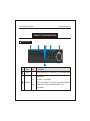
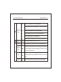
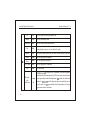
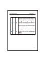
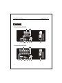
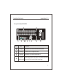
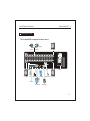
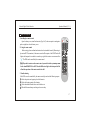
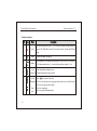
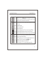
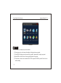
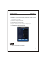
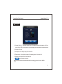
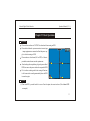
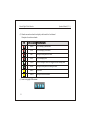
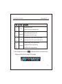
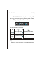
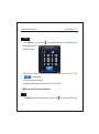
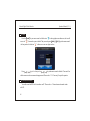
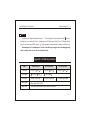
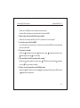
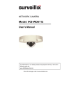
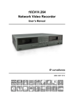
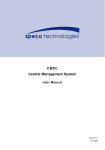
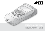
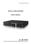
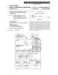
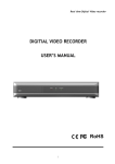
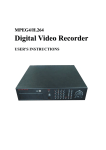
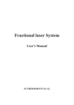
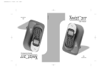
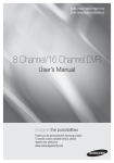
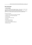
Network Digital Video Recorder
Operation Manual ( V1.1 )
CAUTIONS
In order to ensure your rights and interests, please read this manual carefully before you install
and use the DVR.
Use the appropriate adapter for the DVR.
To protect the main chip from thunder striking, please make sure the ground wire is correctly
connected before using the DVR.
Do not expose the DVR to rain or use it under high humidity circumstance.
This DVR cannot be installed at the places with much dust, and avoid pot ential me chanic al
vibration or impact.
Install this DVR under good air circulation conditions. Do not place it near the heater or under
direct sunlight.
Please choose high quality hard disk (HDD), which could meet the working demand of the DVR.
For its quality, please purchase hard disk from regular merchants, and do not use t he Weste rn
Digital hard disk.
Network Digital Video Recorder
Operation Manual ( V1.1 )
Before connecting to other facilities, please disconnect the power supply and pull the power line
plug out from the power socket.
In case of any solid or liquid coming into the case, please disconnect the power supply immediately, and the DVR can be restarted only after being checked by qualified servicemen.
If the DVR is not in use for a long period of time, please disconnect the power supply and pull
the power line plug out from the power socket.
This is a precise instrument. No internal part can be repaired by the users. If fault occurs, it is
necessary to ask qualified servicemen to repair it or contact the dealer.
Network Digital Video Recorder
Operation Manual ( V1.1 )
Table of contents
Chapter I Product Introduction
6
1.1 Summary
6
1.2 Functions and features
6
Chapter II Operation instructions
8
2.1 Description of front panel
8
2.2 Description of rear panel
12
2.3 Connection figure of rear panel
15
2.4 Description of alarm port in the rear panel
16
2.5 Remote control operation
17
2.6 Mouse operation
20
Chapter III Menu Setup
21
3.1 Summary of menu operation
21
3
Network Digital Video Recorder
3.2 System setup
22
3.3 Camera setup
23
3.4 Record setup
25
3.5 Schedule setup
26
3.6 Motion alarm
27
3.7 PTZ setup
28
3.8 Network setup
29
3.9 Alarm setup
30
3.10 Disk management
31
3.11 User setup
32
Chapter IV Basic Operations
4
Operation Manual ( V1.1 )
33
4.1 Turn on DVR
33
4.2 Live screen
33
4.3 Software update
36
4.4 PTZ control
37
Network Digital Video Recorder
Operation Manual ( V1.1 )
4.5 System information
39
4.6 Log list
40
4.7 Recording preparation
40
4.8 Recording operation
41
4.9 Search, playback and backup
41
4.10 Audio setup
44
4.11 SEQ
44
4.12 Spot output
45
4.13 User login
46
4.14 PC Client software instruction
46
4.15 Power off
47
Appendix 1 Technical parameters
47
Appendix 2 Trouble shooting
48
5
Network Digital Video Recorder
Operation Manual ( V1.1 )
Chapter I Product Introduction
1.1
Summary
This equipment is a standalone digital hard disk video recorder specially designed for security. It adopts the emb-
edded processor and embedded operating system and integrates with latest technologies in IT field, such as video frequency/audio frequency compression/decompression, large capacity hard disk storage, TCP/IP net work remote control etc., investing the system with high intellectualization and stability.
This equipment supports various networks including Ethernet and Internet to realize remote audio/video synchronization. With easy operation, it can be applied to the security for banks, telecom, schools, hospital s, super markets,
residential quarters, factories, companies, warehouses, restaurants, hotels, parks, museums, water conservancy facilities, entertainment places and other fields.
1.2
Functions and features
Support PAL & NTSC video signal input.
Support OSD languages of multiple countries.
Support external alarm, motion detection and time recording.
Support audio recording, audio playing and live mode listening.
6
Network Digital Video Recorder
Operation Manual ( V1.1 )
If the electricity suddenly off while recording, it will record automatically when power on.
Support CMS
Support DDNS
Support network preview, playback, setup, remote recording, PTZ control and camera name setup.
Support IE browsing and Network remote Client.
Support Internet backup ,USB backup.
Support mouse operation with high sensitivity
Support DVD-RW and 1000G hard disk
Support VGA output
Support remote control
Convenient & precise video searching
Control PTZ and speed dome through RS485
Specially designed dedicated file system for video to increase more than 10 times of service life of hard disk
Fully independent from PC platform and free from computer breakdown due to improper operations, complicated
management & operations as well as virus infection, and with high stability
Operating system: Linux
Compressed chip: SOC
7
Network Digital Video Recorder
Operation Manual ( V1.1 )
Chapter II Operation Instructions
2.1 Description of front panel
3
2
1
4
5
6
7
No.
Name
1
Power
Press it to turn on/off the DVR. The same as the " " key in the remote control.
Number keys
a) input numbers
b) keystroke 1~9 : select channels.
c) [0/10+]: input the number "0". Press it twice to select channel 10. Combined
number keys 1~9 to select the channels from channel 11 to 16.
d) input password
Icon
1
2
9
0/10
8
Description
Network Digital Video Recorder
REC
IR
LED Indicator
3
ALARM
light
NET
LOCK
HDD
4
IR Receiver
Record
Operation Manual ( V1.1 )
Record LED indicator light. It is on in recording mode.
Remote signal receiver LED indicator light. It is on in remote control usable
mode.
Alarm LED indicator light. It is on when alarm happened.
Network LED indicator light. It is on in network connection mode.
Lock LED indicator light. It is on in locking mode.
Hard drive LED indicator light. It is flash when hard drive is being used.
Receive signal from remote control. (Do not cover).
Start recording. In PTZ mode, it is used as [Z+] key in the remote control.
Playback/
Pause
Press it to pop up search menu, select a video file to play. Press it to pause in
the process of playback, press it again to play again. In PTZ mod e, it is used
as [Z-] key in the remote control.
Stop
In playback mode, press it to stop playing and return to search menu; in video
recording mode, press it to stop recording; in PTZ mode, press it to view preset
image.
5
Search
Press it to enter search menu. In PTZ mode, press it to set preset image.
9
Network Digital Video Recorder
5
Press it to enter PTZ mode, press again to exit.
PTZ
PTZ
Backup
COPY
Press it to enter backup menu.
Information
INFO
Press it to enter system information menu.
Exit
ESC
Press it to exit from the inferior menu and return to t he sup eri or men u. In
record/playback mode, press it to turn back to live mode.
Sequence
SEQ
In live preview mode, press this key to switch full screen images by sequence.
Audio
AUDIO
Press it to pop up audio setup menu.
Menu
MENU
Press it to pop up the main menu
SPOT output
SPOT
Press it to pop up SPOT setup menu.
Lock
LOCK
Lock the machine.
Direction /
split/
confirm keys
10
Operation Manual ( V1.1 )
a)
are direction keys. In menu mode, select the listed options
upward/downward/leftward/rightward; in PTZ control mode, control the dome
to rotate upward/downward/leftward/rightward.
confirm the selection and
operation. b)
could be Quad, nine-split-screen and16-split-screen
key in live mode. c)
rewind and forward in p layback m ode. Cha nge
the parameters value in menu mode.
Network Digital Video Recorder
Operation Manual ( V1.1 )
6
Shuttle
In playback mode: rotate the shuttle outer ring Leftward / rightward once to fast
backward/forward at 2 speed, rotate it twice to play at 4 speed; Rotate it third
time to play at 8 speed, four times for 16 , five times for32 , six times for
64 ,In menu mode: rotate the shuttle outer ring leftward/rightward once to in
crease/decrease the set value, rotate it leftward /rightward to the end to increase/
decrease the set value successively; rotate the inner ring leftward/rightward to
move the cursor upward/downward.
7
USB port
Connected to USB disk and u sed for system s oftware upgrade or video file
backup. Insert the U disk after turn off t he DVR. You'd better not connect
the mouse here.
-
+
11
Network Digital Video Recorder
2.2 Description of rear panel
Rear panel of 4 channel H.264 DVR:
Rear panel of 8 channel H.264 DVR:
12
Operation Manual ( V1.1 )
Network Digital Video Recorder
Operation Manual ( V1.1 )
Rear panel of 16 channel H.264 DVR:
No.
Port
Description
Video input
Standard BNC port, connected with the camera and speed dome.
Video output
Connected with the video input of the monitor.
Loop output
Standard BNC port, connected with the monotor etc.
"485" port
External alarm port
RS485 devide into A and B. it can control PTZ via the mouse, remote control
and network ClientConnected with alarm inout and output.
13
Network Digital Video Recorder
USB
NET
VGA
Connected to USB pendrive or mouse and usedfor system sof twa re upgr ade
or video file backup; Itsupports hot plug.
Standard RJ-45 network port, connected to network cable and used for remote browse or control.
VGA video signal output port, connected with the VGA port of a computer
monitor.
Audio output
Connected with earphone or cable speaker.
Audio input
Connected with audio input device, e.g. microphone.
SPOT port
Connected with spot output device to view the live image independently.
Power
14
Operation Manual ( V1.1 )
AC 220V or 110V.
Network Digital Video Recorder
Operation Manual ( V1.1 )
2.3 Connection figure of rear panel
Take 16 channel DVR as example to show how to connect.
Video input
camera1
video output
camera16
Power
Loop output
PTZ
USB mouse
VGA output
audio input port spot output
alarm port
network port
audio output
15
Network Digital Video Recorder
Operation Manual ( V1.1 )
2.4 Description of alarm port in the rear panel
Connection figure of alarm input and output.
alarm input
alarm output
4 channel
alarm input
alarm output
8 channel
alarm input
alarm output
16 channel
Description:
(1) "1-16" is alarm input. "NC/NO/COM": Alarm relay output. NC is normal close, NO is normal open, COM is the
public terminal.
(2) "
" It is ground wire.
Prompt: To make the machine work well, please follow the above figures to connect. Please power off each
device before connection.
16
Network Digital Video Recorder
Operation Manual ( V1.1 )
2.5 Remote control operation
1. Installing the remote control
Open the battery cover, install two batteries (Type No.7), make sure positive and negative
poles are right, then close the battery cover.
2. Using the remote control
Before using it, please confirm that batteries have been installed correctly.When using it,
please aim IR TX (transmitter) of the remote control at IR reception of the DVR.Then the IR
light in the front panel is on and the icon on the top-right of the monitor screen turns to blue
"
" The DVR can be controlled by the remote control.
Note: If you don't want to use the remote control, you could set in the system setup menu.
Set the item REMOTE ID as OFF. Then the IR Receiver light in the front panel will be
off and the operation of the remote control is invalid.
3. Trouble shooting
If the DVR can not be controlled by the remote control, please check the following aspects:
1 Check the positive and negative poles of the batteries.
2 Check the electric quantity of the batteries.
3 Check that whether Remote Sensor are blocked or not.
4 Whether Fluorescent lamps are being used or not nearby.
17
Network Digital Video Recorder
Operation Manual ( V1.1 )
Function description:
1
Power
In normal running mode, press " " key to pop up a menu to prompt whether to
turn off. The DVR will be turned off . Press the key about 3 seconds, the DVR will
start.
2
Audio
Audio setup menu will pop up.
1
9
Number
4
Lock
Remote ID
Lock the machine or change the user.
Control the machine by remote control.
Record
Play&pause
Press
key to enter record mode.
In live or record mode, press it to pop up search menu, select a video file to play.
Press it to play, press it again to pause.
Press it to stop playing.
Press it to pop up information menu.
5
Stop
Info
18
Select channels or set up password.Input nunber 0. Press it twice t o select channel
10. Combined number keys 1-9 to select the channels from channel 11 to 16.
3
Network Digital Video Recorder
Forward
5
Rewind
6
MENU
SEQ
SPOT
7
PTZ
AUTO
Z+/ZF+/F-
In playback mode, press
/
key to play images forward or backward at
2X speed. Press it twice to play at 4X speed. Press it third time to play at 8X speed,
four times for 16X, five times for32X, six times for 64X,
Confirm
Exit
Menu
Quad
Eight-split
Sixteen-split
To move the cursor up/ down/ left/ right to select items or modify data. And control
PTZ to move.
Confirm the operation.
Cancel the operation and exit.
Enter into the main menu.
The monitor display quad-screen. Press it to set preview point in PTZ mode.
The monitor display eight-split-screen. Press it to preview in PTZ mode.
The monitor display sixteen-split-screen. Press it to decrease the data in PTZ mode.
Sequence
Spot output
PTZ
AUTO
Zoom in/out
Focus
In live preview mode, press this key to automatically switching full screen images.
Press it to increase the data in PTZ mode.
In PTZ control mode, press it to move the cursor among the digital in the screen.
Enter into PTZ mode. Press it again or press ESC key to exit.
In PTZ control mode, this key is used to zoom in/out.
In PTZ control mode, "F+/F-" key is used to prolong/ shorten the focus.
Direction
ESC
Operation Manual ( V1.1 )
19
Network Digital Video Recorder
7
I+/I-
Operation Manual ( V1.1 )
In PTZ control mode, "I+/I-" key is used to enlarge/ reduce the iris (aperture).
IRIS
CRUISE
8
FOPEN
Standby
FCLOSE
2.6 Mouse operation
USB mouse can be used. Hot swap for mouse is supported. Move the mouse cursor onto the mouse icon to see
the name. Please insert the usb mouse into the usb port of the rear panel.
Left-click the mouse
Right-click the mouse
20
1
2
3
4
Select or cancel " " in the item.
Input password in user log in interface.
Click the close icon on the top-right of the screen to exit from the main menu.
In split-screen mode, click one of the channels to make it full screen. Click it again
to return to split-screen. Switch single channel screens.
5 Switch single channel screens.
1 In live or playback mode, it could swich the single channel image.
2 In menu mode, it could modify the data.
Network Digital Video Recorder
Operation Manual ( V1.1 )
Move the mouse
1 Move the cursor.
2 Move the cursor to the bottom of the screen to pop up the mouse tool bar. Move
the cursor onto the icon to show the name.
Drag the mouse
1
2
Mouse wheels
To change the value or digital in menu mode.
To select shield area in "Camera setup".
To select motion detection area in "Motion alarm".
Chapter III Menu Setup
3.1 Summary of menu operation
In live preview mode, select menu key in the remote control / the front panel or click "
menu to enter the main menu. Press ESC key or click the
close
" icon in mouse
icon that on the top right of the menu to exit from
the main menu. Main menu is as follows.
Please press
/
in the front panel
change the parameter value in the sub-menu. Press
the cursor or move by the mouse. Click"
SAVE
/
in the remote control or left/right-click with the mouse to
/
key in the remote control or in the front panel to move
"to save the value and click "
EXIT
" to exit from the menu.
21
Network Digital Video Recorder
Operation Manual ( V1.1 )
Main menu
3.2 System setup
(1) Time setup: used to adjust the system date and time.
(2) Time format: used to set the format of date display, Asia/Europe/America are optional.
(3) Time DISP POS: display position of time and date, top middle / bottom middle / no display are optional.
(4) Border DISP: to select the color of borders, green/black/white/off are optional.
(5) Video format: to select the video mechanism, PAL/ NTSC are optional. The DVR system will be forced to restartafter switching
22
Network Digital Video Recorder
Operation Manual ( V1.1 )
(6) Remote ID: used to set the remote control ID corresponding to the current machine so as to make remote control,
off/ on/ numbers from 0 to 9 are optional.
(7) Alarm spot pop up: on/off. Open or close the function.
(8) Alarm main pop up: on/off. Open or close the function.
(9) Transparency: set the transparency of the menu. The larger value, the higher transparency.
(10) OSD Language: display the language of the operating system.
2009/09/07 10:19
U.S.(MM_DD_YYYY)
TO P M I D
GREEN
PA L
ON
OFF
OFF
0
ENGLISH
DEFAULT LOAD
SAVE
EXIT
3.3 Camera setup
(1) Camera: used to select the channel to be revised parameters.
23
Network Digital Video Recorder
Operation Manual ( V1.1 )
CAMERA01
01
00
00
00
00
06
22
05
SAVE
SAVE
sec
000
000
000
000
EXIT
EXIT
(2) Camera title: used to set the camera title. Press
key in the remote control / the front pan el to tur n into
bitmap, the camera title couldn't be changed.
(3) Brightness: used to adjust brightness of the channel.
(4) HUE: used to adjust Hue (chroma) of the channel.
(5) Contrast: used to adjust contrast of the channel.
(6) Saturation: used to adjust acutance of the channel.
(7) Sopt time: set the time interval of spot output for the correspond channel, i.e. the display time of each channel.
(8) Mask area setup: Mask area: to shield some area by black square. It will turn to black in surveillance or record mode.
24
(a) Left: set the left border for mask area.
(b) Right: set the right border for mask area.
(b) Top: set the top border for mask area.
(d) Bottom: set the bottom border for mask area.
Network Digital Video Recorder
Operation Manual ( V1.1 )
3.4 Record setup
01
352 288
HIGH
25
01
352 288
HIGH
25
02
352 288
HIGH
25
02
352 288
HIGH
25
03
352 288
HIGH
25
03
352 288
HIGH
25
04
352 288
HIGH
25
04
352 288
HIGH
25
05
352 288
HIGH
25
05
352 288
HIGH
25
06
352 288
HIGH
25
06
352 288
HIGH
25
07
352 288
HIGH
25
07
352 288
HIGH
25
08
352 288
HIGH
25
08
352 288
HIGH
25
SAVE
(1) Resolution: 352
resolution: 720
288
576
EXIT
PAL ; 352
SAVE
240
PAL ; 720 480
NTSC
EXIT
. 4 channel and 8channel DVR could be changed into D 1
NTSC
(2) Quality: the higher video quality, the larger occupied HDD space.
(3) Frame rate: used to set the quantities of images that recorded in one second. 25fps (PAL) and 30 fps ( NTSC) is
real time recording.
(4) Audio: used to turn on or turn off the audio record. Thi s DV R su ppor t 4 chan nel audi o, so cl ick 5~16 channel
audio is invalid.
25
Network Digital Video Recorder
Operation Manual ( V1.1 )
3.5 Schedule setup
ALL
ALL
00
00
24
00
M OT I O N
00
00
00
00
TIME
00
00
00
00
M OT I O N
00
00
00
00
TIME
EXIT
SAVE
(1) Camera: used to select the channel to be set. The parameters are effective for all channels after selecting" All CAM".
(2) Day: used to select the day of video schedule. The parameters are effective for all days after selecting "All DAY".
(3) Segment 1-4: set corresponding video type of relevant time range. The time could be set from 00:00 to 24:00.
Record type could be "time/alarm/motion/alarm+motion".
Note:
The start time must be earlier than the end time, or it will report error and won't exit.
After exiting from this menu, please press
won't startup.
26
REC
key or click the record icon, or the schedule record
Network Digital Video Recorder
Operation Manual ( V1.1 )
3.6 Motion alarm
CAMERA 01
006
015
335
015
230
SAVE
EXIT
(1) Camera: used to select the channel to be set.
(2) Sensitivity: low / high optional from "1-10". The bigger number, the higher sensitivity.
(3) Detect area setup: drag the mouse to set the detection area as light blue square. When motion occurs, the area
turn to red.
27
Network Digital Video Recorder
Operation Manual ( V1.1 )
3.7 PTZ setup
CAMERA 01
9600
01
PELCO_D2
SAVE
EXIT
(1) Camera: to select the channel to be set.
(2) Baudrate: to set baudrate corresponding to the current channel PTZ.
(3) Device ID: to set ID address corresponding to the current channel PTZ.
(4) Protocol: set communication protocol corresponding to the current channel PTZ.
Note:
the above parameters of each channel must be consistent with the setting of PTZ , or it cann't be controlled.
28
Network Digital Video Recorder
Operation Manual ( V1.1 )
3.8 Network setup
DHCP/DDNS
192
168
001
207
192
168
001
001
255
255
255
000
6802
0080
SAVE
EXIT
(1) IP allocation: STATIC and DHCP/DDNS optional. (In static mode, please set IP address, gateway and subnet
mask. In DHCP mode, DVR could get IP from DHCP server. Please refer to the "Client and network manual" in
the accessory CD.)
(2) IP address: It must be unique to avoid colliding with other DHCP.
(3) Gateway and subnet mask: Gateway is the LAN IP address of the router.
(4) DVR port: Transfer date stream, such as video and audio frequency.
(5) IE port: Download ActiveX control. (Default 0080).
Note: When using network browse, IP address/gateway/subnet mask/port of the DVR must be consistent with
the setting of the router.
29
Network Digital Video Recorder
Operation Manual ( V1.1 )
3.9 Alarm setup
01
09
02
10
03
11
04
12
05
13
06
14
07
15
08
16
SAVE
EXIT
SAVE
EXIT
There are two ways for alarm output, Buzzer and Relay. They include three alarm modes:
(1) Video loss alarm(Loss);
(2) Video motion detection alarm(Motion);
(3) Sensor input alarm(Sensor).
Setup way: Press
key on the remote control or c lick with the mouse to display or cancel "
boxes.
"
30
" /"
" is page turning icon.
" in the small
Network Digital Video Recorder
Operation Manual ( V1.1 )
3.10 Disk management
DISK A
074
099
000
FORMAT
SAVE
EXIT
(1) Overwrite: If click " " the previous recorded video will be replaced in turn when the hard disc is full. If not,
record will stop. When you record again, the system will prompt: open overwrite function or format the hard disk.
(2) Disk name: select Disk.
(3) Disk capacity: used to display capacity of the current disk.
(4) Remain capacity: used to display percentage of the remaining capacity of the current disk.
(5) Bad area: used to display bad size of the current disk.
(6)
FORMAT
: used to format the current disk.
Note: You'd better format the hard disk before the first recording to protect the record video file.
31
Network Digital Video Recorder
Operation Manual ( V1.1 )
ADMIN
_ _ _ _ _ _
3.11 User setup
ADMIN
_ _ _ _ _ _
Password is needed to log in by admin. Input the password by click the numbers in the menu or press the numbers
in the remote control / the front panel." " is used to clear the former Number. "
click "
OK
" is used to clear all Numbers. Then
" to enter "USER SETUP" menu.
ADMIN0
000000
ADMIN0
_ _ _ _ _ _
OK
EXIT
SAVE
EXIT
(1) User name: ADMIN0, USER01, USE02 and USER03 are optional and changeable. ADMIN0 is default administrator account.
(2) Password: set separate password for each user. Factory default setting: ADMIN:0000 00, USER01:111111, USER02:222222, USER03:333333.
(3) Permissions: set the operation permissions for users by admin. Users can't operate the function which does not be
selected.
Note: If the DVR is locked, "
" will display in the top right of the screen. Click the icon to input password.
If the icon turns to "
32
", DVR is unlocked.
Network Digital Video Recorder
Operation Manual ( V1.1 )
Chapter IV Basic Operations
4.1 Turn on DVR
Please confirm each item in "AUTION" has been done before turning on DVR.
Please check whether the system connection is correct, input
2009-09-02 12:23:18
/ output equipments are connected well and the power sup ply is on before turning on DVR.
Please make sure video format (PAL or NTSC) of video input and the monitor format meet the requirements.
CH01
L
CH02
L
CH5
CH03
L
CH04
L
After checking without problems, plug in the power cable of
DVR, then turn on the power switch on the rear panel of DVR.
If it is in video recording mode be fore tur ning off last time,
it will resume video recording automatically when the DVR
is turned on again.
4.2 Live screen
(1) Turn on the DVR, you could see the live screen. If no video input, the screen is as above: (Take 4 channel DVR
as example.)
33
Network Digital Video Recorder
Operation Manual ( V1.1 )
(2) Channel name and record mode icon display in the bottom left of each channel.
Description of record icon and mode:
(3)
34
Red M
Is is recording by motion alarm.
Red S
It is recording by sensor alarm.
Red L
Image lost in the process of record.
Red T
It is recording by time.
Green I
DVR is waiting for video event triggered in auto recording mode.
Green L
Image lost in the process of waiting for record.
Yellow ?
No record.
Yellow L
Image lost in no record mode.
Icons in top right of the screen:
Network Digital Video Recorder
Lock
Remote IR
Audio
Operation Manual ( V1.1 )
Unlocked. Click it to lock.
Locked. Click it to login by inputting password.
Remote control is opened. Click it to close.
Remote control is closed. Click it to open.
Audio output is open. Click it to enter into audio setup menu.
Audio output is closed. Click it to enter into audio setup menu.
Hard disk is normal. Click it to pop up info menu.
Infomation
Hard disk is full. Click it to pop up info menu.
No hard disk. Click it to pop up info menu.
(4)
Move the mouse cursor to the icon "
"
in the bottom left of the screen. Mouse tool bar
will pop up as follows.(Take 16 channel DVR as example)
35
Network Digital Video Recorder
Split-screen
Record
Operation Manual ( V1.1 )
Click it to display quad, nine-split-screen an d sixte en-sp lit-s creen .
Click it to starting recording.
play
Click it to enter the menu of search & playback.
Stop
Click it to stop recording or stop playing and return to the search menu.
Main menu
Click it to enter into the main menu.
PTZ
Click it to enter into PTZ control interface.
SEQ
Click it to switch channels in sequence per 5 seconds.
SPOT
Click it to enter into SPOT output setup interface.
Power
Click it to pop up a menu for turning off the power or not.
4.3 Software update
Copy the new version software to the root directory of USB pendrive, the file name is fireusb.
Turn off the DVR. Insert the USB pendrive with software into USB port in DVR front panel, then power on again.
30 seconds later, it will pop up "Software updating" and "Time: s" on the screen, the system update automatically.
When "Update ok, reboot please!" pop up on the screen, update is finished. Please pull out the U disk and restart
36
Network Digital Video Recorder
Operation Manual ( V1.1 )
the machine. If "Update fail, try again!" pop up more than 4 times, please contact after-sales service d epar tment
to deal with it.
In the process of update, please ensure no power breakdow n and do n't pull out USB pendrive , or update will be
unsuccessful.
Make sure U disk works in good condition so as to avoid abnormal performance in the process of update.
4.4 PTZ control
In live or recording mode, press
PTZ
key in the remore control / the front pan el or cli ck t he "
" icon in
mouse menu to ente r PTZ
control interface.
01
02
03
04
37
Network Digital Video Recorder
Operation Manual ( V1.1 )
Characters "PTZ: CAM01 SPEED:16 DATA:01" display on the top of the monitor screen, indicating the DVR is
under PTZ control. PTZ control parameters of each channel can be modified in the system menu. Press
again or press ESC key or click the icon "
PTZ
key
" to exit from PTZ control mode. When the mouse moved to the
bottom of screen, it will display the following icons.
Please check the following table for the symbol of these icons:
Direction icon. Control the camera
Control the dome camra to rotate automatically.
to turn up, down, left, and right.
Click the icon again to stop it.
Zoom icon. Control the focal distance of zoom
Preset key.
Preview preset key.
Shut off PTZ menu.And exit from PTZ control.
Modify the parameter:
When the cursor is on "PTZ:CAM01 SPEED:16 DATA:01" , you could select camera,set the speed and preset the
38
Network Digital Video Recorder
Operation Manual ( V1.1 )
data of image point. Select the item which need modify by pressing
item directly with the mouse.Then change the data by pressing
SPOT
/
key in the remote control or clicking the
SEQ
in the remote control or left/right-
click with mouse.
Preset operations (include set and view)
(1) Select image point in the selected camera by "
such as 01, then press
" key, set a number for the image point in "DATA",
key on the remote control or click "
" icon. Set is finished.
(2) To view of image point which has been preset,you could select the corresponding number in "DATA", then press
9ch split key
on remote control or click "
" icon by mouse.
4.5 System information
1
074
Press
INFO
key or click the icon "
" with mouse, it will
099
000
display the interface of system information as following.
000
(1) HDD QTY: the number of the hard drive wh ich conn ected
with the DVR
(2) Total capacity: total size of all hard drives in the DVR.
DVD-RW not included.
(3) Remain capacity: percentage of the remain size of hard drive.
2 0 0 9 / 0 8 / 1 9 11
40
00
2009/09/07 10
20
00
w w w. d v r s e r v e r. n e t : 2 5 A 0 0 0 1 @
192 . 168 . 001 . 207
Sep 15
2009 12 : 01 : 47
Sep 14
2009 16 : 05 : 08
Sep 12
2009 02 : 32 : 39
6802
EXIT
(4) Coverage: percentage of overwriting of hard drive.
39
Network Digital Video Recorder
Operation Manual ( V1.1 )
(5) Bad area: bad size of the hard drive.
(6) Record start time: the earliest record time.
(7) Record end time: the latest record time.
4.6
Log list
2009/08/19
Press
INFO
2009/08/19
key twice to pop up log list menu.
It is used to check the information of power on/off and recording
etc. Set the time segment, then click "Search", it will display the
information.
01
02
03
04
05
06
07
08
09
10
SYSTEM
SYSTEM
CAM08
CAM07
CAM06
CAM05
CAM04
CAM03
CAM02
CAM01
POWER ON
POWER ON
S TO P L O S S
S TO P L O S S
S TO P L O S S
S TO P L O S S
S TO P L O S S
S TO P L O S S
S TO P L O S S
S TO P L O S S
2009/08/19
2009/08/19
2009/08/19
2009/08/19
2009/08/19
2009/08/19
2009/08/19
2009/08/19
2009/08/19
2009/08/19
20:12:58
04:18:59
11:35:41
11:35:41
11:35:41
11:35:41
11:35:41
11:35:41
11:35:41
11:35:41
01/10
SEARCH
EXIT
4.7 Recording preparation
Make sure all the equipment is power on before recording. Make sure that there is video input and test audio in
put by live monitoring.
Press
INFO
key to check disk information and the remaining capaci ty of the ha rd drive. I f there is n't muc h
capacity left,pls firstly consider to replace hard drive, backup the video or overwrite the video.
If necessary, enter the "RECORD SETUP" to set audio recording,video image quality and recording frame rate.
If DVR is equipped several hard drive, please enter "DISK MANAGEMENT" to check the hard drive information
40
Network Digital Video Recorder
by press
Operation Manual ( V1.1 )
key in the front panel or press
key in the remote control or click disk name
with mouse.
4.8 Recording operation
Firstly confirm that recording mode of each channel in schedule setup(time/alarm/motion/alarm+motion) and time
segment setup.
Start recording: Press the key
"
in the front panel / remote control of DVR to start recording. Or click the icon
" by mouse.
When DVR is under recording, the HDD light in the front panel will flash. Please select the recording channel
according to fact need so as to save more HDD capacity.
It will be back to live when you press icon
"
" by mouse to be back to live. Press
in the remote control / the front panel. Also you could click icon
ESC
key and select " YES" to stop recording.
4.9 Search,playback and backup
Press
key or click "
" icon in live or record mode to enter search menu.this menu is used for search, play-
back and backup video file. Adjusting time to search and select video file.
(1) Valid time: It shows the valid time from the earliest recording time to the latest recording time.
(2) You could select any four channels to playback simultaneously as you like or single channel to playback by select
the number in the CH box. Press
key in the remote control or click "
" icon with the mouse to playback
8 channel simultaneously.
41
Network Digital Video Recorder
Operation Manual ( V1.1 )
(3) Backup device: You culd select DVD(1.5G) or USB pendrive i n device item. The ma ximum cap acity for DVD
disk should not exceed 1.5G.
(4) In option of date and start time, input the date and time you need to play, you could press
front panel or press
the arrow "
key in the
key in the remote control to select the start time. Or you could use mouse to drag
" under the time scale to select the start time, and click the icon "
PLAY
" to playback. When
playback finshed, it will turn back to the search menu automatically.
2009/08/19
DVD
2009/09/17
1.5G
01
03
02
04
2009/09/07
9
CALCULATE
(5)
CALCULATE
10 55
55
BACKUP
PLAY
EXIT
: Before backup, please calculate the capacity of the video first. Click th e icon "
CALCULATE
" to calc-
ulate the video you need to backup. If the video capacity is large, it will remind you waiting until calculation finished.
(6)
42
BACKUP
: Before backup,please connect the backup device to DVR, e.g. USB pendrive, USB HDD , etc. You
Network Digital Video Recorder
Operation Manual ( V1.1 )
could select the time segment you need to backup with mouse. And click the "Backup" icon to start backup.The process
will last for a few minutes. When backup finished, please remove the device from DVR.
(7) Please note that the size of video file should not exceed the maximum capacity of backup device. If system cannot find backup device, it will be back to search menu.
(8) On the bottom of screen, it will display the playback mode:
pause.
normal speed playback
/
/
/
stop playback.
/
/
/
/
Twice/4 times/8 times/16times/32 times/64 times forward.
/
/
/
Twice/4 times/8 times/16times/32 times/64 times rewind.
When you move the mouse cursor to the bottom of screen,it will display mouse icon while it is under playback:
"
" click this icon to fast rewind when playback.
"
" click this icon to fast forward when playback
Note: This DVR could not support sixteen channels playback, so clicking "
" is invalid.
43
Network Digital Video Recorder
Operation Manual ( V1.1 )
Audio setup
Press the
AUDIO
in the front panel or press the
key in remote control or click the icon "
" with mouse to enter
audio setup interface.Take 16
channel DVR as example.
CH01
CH02
CH03
CH04
CH05
CH06
CH07
CH08
CH09
CH10
C H 11
CH12
CH13
CH14
CH15
CH16
ENTER
(1) Mute: Select mute, then there is no audio output in live mode and the aud io ic on will turn to "
"
ENTER
" . Press
"key to save this setup.
(2) Network: select network audio output.
(3) It supports 4ch audio input and 1ch audio output. Click "5~16" CH is invalid.
Note: No audio output in 4 or 8 channel playback mode.
SEQ
Press
44
SEQ
in the remote control / the front panel. or click t he icon "
" . with mouse t o start SEQ. Then it
Network Digital Video Recorder
will display the icon "
Operation Manual ( V1.1 )
" on top right of screen. It will switch automatically between 1 channel, quad, 8ch and
16ch.The interval is 5 second. Click the icon "
" with mouse or press
SEQ
key in the remote control to end SEQ.
4.12 Spot output
In live preview mode, press
SPOT
key in remote control or click "
" icon with mouse to enter SPOT output
setup menu. Take 16 channel DVR as example.
(1) AUTO: After select this item, the system will output sequence image according to default SPOT out put interval time.
CH01
CH02
CH03
CH04
You could set the time for SPOT output as the following
CH05
CH06
CH07
CH08
operation.
CH09
CH10
C H 11
CH12
Enter "Camera setup" menu. Move the cursor on "SPOT TIC
H
1
3
C
H
1
4
C
H
1
5
CH16
ME", then you could set the time by pressing
key
ENTER
or left/ right-click with the mouse. It could be set as 0 second
or 5--30 seconds. If output interval of some channel is 0 second, that channel won't output. For example, 8 seconds for channel 1, 0 seconds for channel 2, 3 seconds for channel 3; then in spot output mode, channel 1 will turn to channel 3 after the image displaying 8 seconds, channel 3
will turn to the next channel after the image displaying 3 seconds and so on.
(2) If any channel from CH1 to CH16 is selected, the image of those channels will be spot output.
Note: Video input is necessary for Spot output.
45
Network Digital Video Recorder
Operation Manual ( V1.1 )
4.13 User login
Press the Lock key on remote control or click the icon "
turn to red "
" on the top right screen with mouse, the icon will
". It means the system is locked. Then you need to press Lock /
the front panel or click the icon "
ESC
key in the remote control/
" with mouse to enter user login interface.
ADMIN0
_ _ _ _ _ _
OK
Press
key in the front panel or
EXIT
key in the remote control or click the "User name" box
with the mouse to select user name and input password. Please refer to "3.11 User setup" for specific operation.
4.14 PC Client software instruction
You could control the DVR via client software on PC. Please refer to < Client and network manual> attached in CD.
46
Network Digital Video Recorder
Operation Manual ( V1.1 )
4.15 Power off
Normal power off: Stop all the operations, press "
" in the front panel / remote control or click "
" icon on
bottom left of screen. And select " Enter " to make it power off. When power off, the" Power" LED light will turn
green. If you want to restart DVR, p ress the "
" in the front panel / remote control for 3 second and it will power on.
Abnormal power off: Abnormal power off refer to shut off the power supply when it is running(especially
under recording). Please try your best to avoid such accident.
Appendix 1 Technical parameters
Items
4CH H.264 DVR
8CH H.264 DVR
16CH H.264 DVR
Video input
1.0Vp-p/75 ,BNC 4
1.0Vp-p/75 ,BNC 8
1.0Vp-p/75 ,BNC 16
Video output
1 1.0Vp-p/75 ,BNC 1
2 VGA output 1
Alarm input
4ch opto-coupler input
8ch opto-coupler input
Alarm output
Relay output,NO,NC,COM
Alarm mode
Sensor alarm, motion detection,video loss,HDD full alarm
16ch opto-coupler input
47
Network Digital Video Recorder
Items
Live resolution
Record resolution
Audio
Network port
Operation Manual ( V1.1 )
4CH H.264 DVR
8CH H.264 DVR
720 576(PAL) ; 720 480(NTSC)
352 288/ 720 576 (PAL) ; 352 240/720 480 (NTSC) 352 288(PAL)352 240(NTSC)
Av 4ch input, BNC 1ch output
RJ-45
USB port
HOST 2.0 in front panel, HOST 1.0 in rear panel
HDD port
SATA
PTZ control
RS485
Power
AC 220V / 110V
Appendix 2 Trouble shooting
FAQ :
1. Why cannot detect hard drive?
48
16CH H.264 DVR
Network Digital Video Recorder
Operation Manual ( V1.1 )
Default cause: The HDD power line or data cable is not connected well.
Resolution: Please check the power cable and data cable. And format the HDD.
2. Why the remote control not work? But the mouse is workable.
Default cause: The remote control ID was set "OFF" in system menu. Or it was set wrong ID.
3. Can we delete a part of video file in HDD?
No, it can't be done. For the reason of safty, we can't delete a part of video file in HDD. If you want to delete them,
please try to format HDD.
4. Why alarm is not workable?
Default cause: 1 The schedule setup is wrong. 2 Alarm setup is wrong. 3 Alarm cable connection is wrong.
4 Alarm input signal is wrong 5 It is not recording.
5. Why cannot find the video file in search menu after recording?
Default cause: 1 The time segment for search is wrong.
2 HDD cable is not connected well. 3 System date
was wrong. 4 The system format was changed.
6. Why there are no video output when connect DVR with camera?
Default cause: 1 BNC connector not connect well. 2 The system format is different between DVR and camera. 3 Modified the system date back.
49
Network Digital Video Recorder
Operation Manual ( V1.1 )
NOTE
The operation manual is for reference only. Products may vary
Products are subject to update without further notice.
Please contact the customer service department for latest program and supplimentary informaton
Any disputes or doubts in products description are subject to our final explanation.
50