1
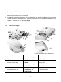
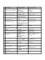
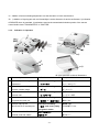
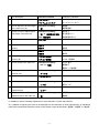
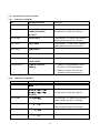
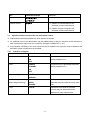
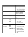
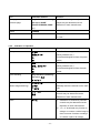
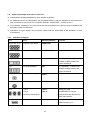
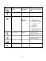
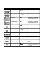
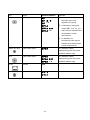
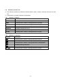
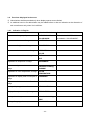
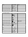
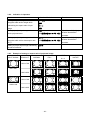
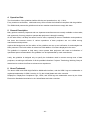
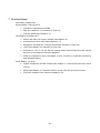
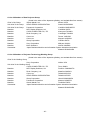
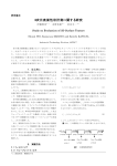
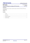
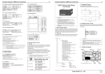
Guideline for Data Projector Indications Fourth Edition Revised in July 2014 Projector Terminology Working Group Japan Business Machine and Information System Industries Association (JBMIA) -1- Table of Contents 1. Purpose ............................................................................................................................................... 3 2. Scope .................................................................................................................................................. 3 3. Indication Method .............................................................................................................................. 3 3.1. Parts of the main unit in user’s manual .................................................................................... 3 3.1.1. Indication in English ............................................................................................................... 4 3.1.2. Indication in Japanese ........................................................................................................... 6 3.2. Accessories in user’s manual .................................................................................................... 8 3.2.1. Indication in English ............................................................................................................... 8 3.2.2. Indication in Japanese ........................................................................................................... 8 3.3. Operation buttons on the main unit and remote control ......................................................... 9 3.3.1. Indication in English ............................................................................................................... 9 3.3.2. Indication in Japanese .......................................................................................................... 11 3.4. Signal input/output terminals on main unit ............................................................................ 13 3.4.1. Indication in English ............................................................................................................. 13 3.4.2. Indication in Japanese ......................................................................................................... 15 3.5. Indicators on main unit............................................................................................................. 17 3.5.1. Indication in English ............................................................................................................. 17 3.5.2. Indication in Japanese ......................................................................................................... 17 3.6. Functions displayed in the menu ............................................................................................ 18 3.6.1. Indication in English ............................................................................................................. 18 3.6.2. Indication in Japanese ......................................................................................................... 19 3.7. Functions related to power operation ..................................................................................... 20 3.7.1. Indication in English ............................................................................................................. 20 3.7.2. Indication in Japanese ......................................................................................................... 21 3.8. Functions related to aspect ratio of the projected image...................................................... 21 3.8.1. Indication in English ............................................................................................................. 21 3.8.2. Indication in Japanese ......................................................................................................... 22 3.8.3. Example of setting an aspect ratio of projected image......................................................... 22 4. Operation Rule ................................................................................................................................. 23 5. General Description ......................................................................................................................... 23 6. About Trademark .............................................................................................................................. 23 7. Revision History ............................................................................................................................... 24 A List of Members of Data Projector Group .......................................................................................... 25 A List of Members of Projector Terminology Working Group ............................................................. 25 -2- 1. Purpose The purpose of the guideline is to unify indications used by products of each company so that users can use the products with ease. 2. Scope The guideline is designed to cover Japanese and English terminology of the following items regarding data projectors. The indications in any other language shall be based on the translation from English or Japanese version. Parts and accessories in user’s manual Operating buttons on main unit and remote control Signal input/output terminals on main unit Indicators on main unit Functions displayed in the menu Functions related to power operation Functions related to aspect ratio of the projected image Data projectors in the guideline shall mean front projection type projectors with computer inputs and capable of enlarging images, used for general conferences and educational sites. 3. Indication Method Following indications are permitted in the discretion of each manufacturer. ※ Any name not set forth in the table shall be excluded. ※ All the names listed in the table do not necessarily have to be listed or described. ※ Alternative indications using icons. ※ Indications using uppercases, lowercases and blank space and symbols such as periods (.), slashes (/), and hyphens (-). ※ In the case where functions covered are unique to each manufacturer. ※ Regarding the indication in Japanese, the use of alphabets, katakana, and long sound phonetic letters of indication in English shall be allowed. Example of indication in Japanese by using alphabets: English) STANDBY, Japanese) STANDBY Example of indication in Japanese by using katakana: English) STANDBY, Japanese) スタンバイ Example of indication in Japanese by using long sound phonetic letters: English) COMPUTER, Japanese) コンピューター 3.1. Parts of the main unit in user’s manual ※ Illustrations used in this clause are conceptual diagrams to check on parts defined in the guideline. -3- ※ Abbreviations shall be permitted only when indication spaces are limited. (Example: “INPUT/OUTPUT” → “I/O”) ※ An additional word or an abbreviation may be added before or after an indication at the discretion of each manufacturer only when it is insufficient. ※ An additional word which indicates the place or adjustment may be added, and the way of description is at the discretion of each manufacturer (Example in English: FOOT→ REAR ADJUSTABLE FOOT; Example in Japanese: フット→後部角度調整脚). 3.1.1. Indication in English ⑦ ④ ⑩ ② ① ⑭ ③ ⑤ ⑫ ⑬ ⑮ ⑨ ⑧ ⑪ ⑧ ⑯ ⑰ ⑥ ⑰ ⑱ ⑲ All rights reserved for above illustrations. ① Part description Indication method Example of indication Operation part for image focus Indication including FOCUS RING adjustment ② Operation part to enlarge or contract a whole image ③ Indicator to show the status of the main unit ④ Generic name of the button area to operate the main unit “FOCUS” Indication including FOCUS LEVER ZOOM RING ZOOM LEVER “ZOOM” Indication including “INDICATOR” Indication including “CONTOROL” or “OPERATION” -4- POWER INDICATOR INDICATOR PANEL CONTROLS OPERATION PANEL ⑤ ⑥ ⑦ Part description Indication method Example of indication Generic name of the PORT PORTS INPUT/OUTPUT terminal port TERMINAL TERMINALS INPUT / OUTPUT I/O PANEL Part to cover INPUT/OUTPUT CABLE COVER CABLE COVER terminal ports and cables TERMINAL COVER TERMINAL COVER Part to cover the lamp unit LAMP COVER LAMP COVER LAMP UNIT COVER ⑧ ⑨ Part to adjust the tilt and height Indication including FRONT FOOT of the main unit (*A) “FOOT” ADJUSTABLE FEET Button or lever to adjust the tilt Indication including FOOT LEVER and height of the main unit “FOOT” or “terms to ADJUSTABLE LEVER indicate adjustment” and “design name” ⑩ Built-in speaker SPEAKER SPEAKER ⑪ Intake port of ambient air for Indication including INTAKE VENT cooling ⑫ Exhaust port in the main unit “INTAKE” Indication including “EXHAUST” ⑬ INTAKE PORT EXHAUST VENT EXHAUST PORT Sensor/Receiver of the remote REMOTE CONTROL REMOTE CONTROL SENSOR control (*B). SENSOR REMOTE CONTROL REMOTE CONTROL RECEIVER RECEIVER ⑭ ⑮ Power socket of the main unit Filter to prevent dust inflow into the main unit Indication including AC IN TERMINAL “AC” or “POWER” POWER SOCKET Indication including “FILTER” FILTER AIR FILTER ⑯ Part to cover the filter FILTER COVER FILTER COVER ⑰ Lens for projection Indication including LENS PROJECTION LENS “LENS” ⑱ Mirror for reflecting the projection light ⑲ Output area of the reflected Indication including MIRROR “MIRROR” PROJECTION WINDOW projection light in the main unit -5- PROJECTION WINDOW *A: Addition of terms indicating adjustment is at the discretion of each manufacturer. *B: 1) Addition of signal types such as infrared light is at the discretion of each manufacturer, 2) Indication of REMOTE alone is permitted, 3) Indications used at the transmission/emission portion of the remote control shall include “TRANSMITTER” or “EMITTER”. 3.1.2. Indication in Japanese ⑦ ④ ⑩ ② ① ⑭ ③ ⑤ ⑫ ⑬ ⑮ ⑨ ⑧ ⑪ ⑧ ⑯ ⑰ ⑥ ⑰ ⑱ ⑲ All rights reserved for above illustrations. ① Part description Indication method Example of indication Operation part for image focus Indication including フォーカスリング adjustment ② Operation part to enlarge or contract a whole image ③ Indicator to show the status of the main unit ④ Generic name of the button area to operate the main unit ⑤ Generic name of the INPUT/OUTPUT terminal port “フォーカス” Indication including フォーカスレバー ズームリング ズームレバー “ズーム” Indication including “インジケータ” Indication including “操作部” or ”操作パネル” Indication including “端子” and clearly imply 電源インジケータ インジケータ部 操作部 操作パネル 接続端子部 入出力端子パネル the generic name. ⑥ Part to cover INPUT/OUTPUT ケーブルカバー ケーブルカバー terminal ports and cables 端子カバー 端子カバー -6- ⑦ ⑧ Part description Indication method Example of indication Part to cover the lamp unit ランプカバー ランプカバー ランプユニットカバー ランプユニットカバー Indication including 調整脚 Part to adjust the tilt and height of the main unit (*A) ⑨ Button or lever to adjust the tilt and height of the main unit 後部調整脚 “脚” Indication including “脚” or “調整を示す用語” 脚ボタン 高さ調整レバー and “構造名称” 角度調整用ボタン ⑩ Built-in speaker スピーカ スピーカ ⑪ Intake port of ambient air for 吸気口 吸気口 cooling 吸気孔 吸気孔 Exhaust port in the main unit 排気口 排気口 排気孔 排気孔 Sensor/Receiver of the remote リモコン受光部 リモコン受光部 control (*B) リモコン受信部 リモコン受信部 Power socket of the main unit Indication including AC IN 端子 ⑫ ⑬ ⑭ “AC” or ”電源” 電源端子 電源コード接続部 ⑮ Filter to prevent dust inflow into the main unit Indication including フィルタ “フィルタ” ⑯ Part to cover the filter フィルタカバー フィルタカバー ⑰ Lens for projection Indication including レンズ 投写レンズ “レンズ” ⑱ Mirror for reflecting the projection light ⑲ Output area of the reflected projection light in the main unit Indication including ミラー “ミラー” Indication including 投写窓 投映窓 “窓” *A: Addition of terms indicating adjustment is at the discretion of each manufacturer. *B: 1) Addition of signal types such as infrared light is at the discretion of each manufacturer, 2) Indications used at the transmission/emission portion of the remote control shall include “送信部”, “発信部” or “発光部”. -7- 3.2. Accessories in user’s manual 3.2.1. Indication in English Item Indication Example Remarks Power cord POWER CORD “POWER CABLE” is permitted. Computer cable COMPUTER CABLE Addition of terminal type information is at COMPUTER CABLE the discretion of each manufacturer. (D-sub15) DVI-D cable The indication “-D” shall not be omitted to DVI-D CABLE clearly identify the type of a terminal. DVI-I cable The indication “-I” shall not be omitted to DVI-I CABLE clearly identity the type of a terminal. HDMI cable HDMI CABLE USB cable USB CABLE Lens protector LENS CAP LENS COVER Remote control ① Addition of wired/wireless is at the REMOTE CONTROL discretion of each manufacturer. REMOTE ② Addition of signal types is at the discretion of each manufacturer. 3.2.2. Indication in Japanese Item Indication Example Remarks Power cord 電源コード “電源ケーブル” is permitted. Computer cable コンピュータケーブル Addition of terminal type information is at コンピュータケーブル the discretion of each manufacturer. (D-sub15) DVI-D cable The indication “-D” shall not be omitted to DVI-D ケーブル clearly identify the type of a terminal. DVI-I cable The indication “-I” shall not be omitted to DVI-I ケーブル clearly identity the type of a terminal. HDMI cable HDMI ケーブル USB cable USB ケーブル -8- Item Indication Example Lens protector レンズキャップ Remarks レンズカバー Remote control ① Addition of wired/wireless is the リモコン discretion of each manufacturer. ② Addition of types of signal is the discretion of each manufacturer. 3.3. Operation buttons on the main unit and remote control ※ Abbreviations shall be permitted only when spaces are limited. ※ An additional word or an abbreviation may be added before or after an indication at the discretion of each manufacturer only when it is insufficient. (Example: COMPUTER 1, etc.) ※ Any indication consisting of 2 or more words may be put together into a group or may be divided at the discretion of each manufacturer is permitted. 3.3.1. Indication in English Part Indication method Remarks Main power MAIN It shall conform to applicable standards ON (safety standard, etc.). OFF Power POWER It shall conform to applicable standards STANDBY (safety standard, etc.). ON OFF Input switching INPUT SOURCE Individual image switching COMPUTER For any other input, indications shall (Direct image switching) VIDEO basically match the terminal on the main S-VIDEO unit. FOCUS Indications for manual or powered Focus controls may be determined at the discretion of each manufacturer. -9- Part Indication method Remarks Zoom ZOOM ① Indications for manual or powered controls may be determined at the discretion of each manufacturer. ② “Zoom” shall mean any function to enlarge or contract a whole image (it does not mean functions to enlarge or contract a part of an image). Lens shift Indications for manual or powered LENS SHIFT controls may be determined at the discretion of each manufacturer. Menu MENU Keystone correction KEYSTONE Non-display of image BLANK Any function to stop displaying only images Mute MUTE MUTING Non-display of image and AV MUTE mute AV MUTING permitted as both AUDIO and BLANK VISUAL are halted. ① “AV MUTE” and “AV MUTING” are ② ”BLANK” is permitted as the non-display of image is primary while the mute is secondary. Changing aspect ratio RESIZE ASPECT Partial enlargement ① “Partial enlargement” shall mean MAGNIFY Any indication containing any function to enlarge/contract only the word “ZOOM” a part of an image. (D.ZOOM, E-ZOOM, etc.) ② When using any indication containing the word “ZOOM”, a terminology to distinguish between whole and partial image enlargement/contraction shall be added. -10- Part Indication method Remarks Next page Any indication containing Indications referring to next/previous Previous page the word “PAGE” pages may be determined at the (PAGE UP/DOWN, PAGE discretion of each manufacturer. +/-) Pause FREEZE Volume VOLUME The abbreviation shall be either “VOL” or “VOL.” 3.3.2. Indication in Japanese Part Indication method Remarks Main power 主電源 It shall conform to applicable standards 電源スイッチ (safety standard, etc.). 入 It shall be distinguished from the power 切 button. 電源 It shall conform to applicable standards 待機、スタンバイ (safety standard, etc.). 入 It shall be distinguished from the main 切 power. Power Input switching Any indication containing the word “入力” インプット Individual image switching コンピュータ For any other input, indications shall (Direct image switching) ビデオ basically match the terminal on the main S-ビデオ unit. フォーカス Indications for manual or powered 焦点 controls may be determined at the Focus discretion of each manufacturer. Zoom ① Indications for manual or powered ズーム controls may be determined at the discretion of each manufacturer. ② “ズーム” shall mean any function to enlarge or contract a whole image (it does not mean functions to enlarge or contract a part of an image). -11- Part Indication method Remarks Lens shift レンズシフト Indications for manual or powered controls may be determined at the discretion of each manufacturer. Menu メニュー Keystone correction Any indication containing The word “台形” shall be used in the word “台形” combination with the words that signify キーストーン adjustment or compensation. ブランク Any function to stop displaying only 映像消去 images Non-display of image Mute ミュート 消音 Non-display of image and AV ミュート “ブランク” is permitted as the mute ブランク non-display of image is the main function while the mute is the sub-function. Changing aspect ratio リサイズ アスペクト Partial enlargement Any indication containing ① Partial enlargement shall mean any the word “ズーム” or function to enlarge/ contract only a “拡大” part of an image. (D.ズーム、E-ズーム、etc) ② A terminology to distinguish between whole and partial image enlargement/contraction shall be added. Next page Any indication containing Indications referring to next/previous Previous page the word “ページ” pages may be determined at the (ページ送り、ページ戻し、 discretion of each manufacturer. etc) Pause 静止 フリーズ Volume 音量 -12- 3.4. Signal input/output terminals on main unit ※ Abbreviations shall be permitted only when spaces are limited. ※ An additional word or an abbreviation may be added before or after an indication at the discretion of each manufacturer only when it is insufficient (Example: COMPUTER 1, AUDIO IN, etc.). ※ Any indication consisting of 2 or more words may be put together into a group or may be divided at the discretion of each manufacturer. ※ Indications for input signals via conversion cables shall be determined at the discretion of each manufacturer. 3.4.1. Indication in English Part Signal Indication Method Mini D-sub 15 pin Computer input signal COMPUTER Mini D-sub 15 pin Computer output signal MONITOR OUT DVI-D DVI (Digital) DVI-D Remarks The indication “-D” shall not be omitted to clearly identify the type of a terminal. DVI-I DVI (Analog/Digital) DVI-I The indication “-I” shall not be omitted to clearly identify the type of a terminal. RCA Composite video signal VIDEO Mini DIN 4 pin S VIDEO signal S-VIDEO RCA Y Pb Pr Y Pb Pr Adding the word Y Cb Cr Y Cb Cr “COMPONENT” may be determined at the discretion of Component video signal each manufacturer. HDMI HDMI (See remarks) It shall conform to guidelines of HDMI licensing LLC. -13- Part Signal Indication Method Remarks DisplayPort DisplayPort (See remarks) It shall conform to guidelines of VESA. Stereo mini jack Audio input signal AUDIO Indications for multiple audio AUDIO IN terminals may be put together into a group. RCA Audio input signal AUDIO ① Indications for multiple audio AUDIO L R terminals may be put AUDIO IN together into a group. AUDIO IN L R ② Combinations among the words AUDIO, IN, L, and R may be determined at the discretion of each manufacturer. ③ An indication for monophonic audio may be determined at the discretion of each manufacturer. Stereo mini jack Audio output signal AUDIO OUT Any indication clearly distinguishing input and output terminals shall be used. RCA Audio output signal AUDIO OUT L R Any indication clearly distinguishing input and output terminals shall be used. RJ-45 Network LAN Stereo mini jack Remote control REMOTE -14- 3.4.2. Indication in Japanese Part Signal Indication Method Mini D-sub 15 pin Computer input signal コンピュータ Mini D-sub 15 pin Computer output signal モニタ出力 DVI-D DVI (Digital) DVI-D Remarks The indication “-D” shall not be omitted to clearly identify the type of a terminal. DVI-I DVI (Analog/Digital) DVI-I The indication “-I” shall not be omitted to clearly identify the type of a terminal. RCA Composite video signal ビデオ Mini DIN 4 pin S VIDEO signal S-ビデオ RCA Y Pb Pr Y Pb Pr Adding the word “コンポーネン Y Cb Cr Y Cb Cr ト” may be determined at the discretion of each manufacturer. Component video signal HDMI HDMI (See remarks) It shall conform to guidelines of HDMI licensing LLC. DisplayPort DisplayPort (See remarks) It shall conform to guidelines of VESA Stereo mini jack Audio input signal 音声 Indications for multiple audio 音声入力 terminals may be put together into a group. -15- Part Signal Indication Method Remarks RCA Audio input signal 音声 ① Indications for multiple audio 音声 左 音声 LR 右 terminals may be put together into a group. ② Combinations among the 音声入力 音声入力 左 右 words 音声, 入力, 左, 右, L 音声入力 L R and R may be determined at the discretion of each manufacturer. ③ An indication for monophonic audio may be determined at the discretion of each manufacturer. Stereo mini jack Audio output signal Any indication clearly 音声出力 distinguishing input and output terminals shall be used. RCA Audio output signal 音声出力 Any indication clearly 音声出力 左 右 distinguishing input and output 音声出力 terminals shall be used. RJ-45 Network LAN Stereo mini jack Remote control リモート リモコン -16- LR 3.5. Indicators on main unit ※ The following indications of indicators shall be used for status, cautions, warnings and errors on main unit. ※ Combinations of multiple indicators are permitted. 3.5.1. Indication in English Indication Description POWER Indicating status, cautions, warnings and errors of power LAMP Indicating status, cautions, warnings and errors of lamps LIGHT Indicating status, cautions, warnings and errors of lights TEMP Indicating status, cautions, warnings and errors of temperatures WARNING Indicating warnings and errors STATUS Indicating status, cautions, warnings and errors on main unit FILTER Indicating status, cautions, warnings and errors of filters 3.5.2. Indication in Japanese Indication Description 電源 Indicating status, cautions, warnings and errors of power 光源 Indicating status, cautions, warnings and errors of lamps or lights 温度 Indicating status, cautions, warnings and errors of temperatures 警告 Indicating warnings and errors 状態 Indicating status, cautions, warnings and errors on main unit フィルタ Indicating status, cautions, warnings and errors of filters -17- 3.6. Functions displayed in the menu ※ Abbreviations shall be permitted only when display spaces etc are limited. ※ An additional word or an abbreviation may be added before or after an indication at the discretion of each manufacturer only when it is insufficient. 3.6.1. Indication in English Function Indication Method Remarks Adjustment of image quality PICTURE MODE The indication “MODE” shall not COLOR MODE be omitted in “COLOR MODE”. Adjustment of contrast of image CONTRAST Adjustment of brightness of image BRIGHTNESS Adjustment of color saturation of image SATURATION COLOR Adjustment of tint and hue of image TINT HUE Adjustment of sharpness of image SHARPNESS Adjustment of gamma characteristic of Indication including image “GAMMA” Adjustment of color temperature of image COLOR TEMPERATURE Adjustment of display area of outer part of OVERSCAN image Adjustment of noise reduction effect of NOISE REDUCTION image Setting of display position of menu MENU POSITION Display of test pattern to adjust image TEST PATTERN Setting of the iris system Indication including “IRIS” Setting of language of menu, etc. LANGUAGE -18- Function Indication Method Setting behavior at standby state Indication including Remarks “STANDBY” Initializing of setting of function in menu Indication including “RESET” Setting of when used at high altitude HIGH ALTITUDE Setting of display information of filter FILTER MESSAGE 3.6.2. Indication in Japanese Function Indication Method Adjustment of image quality 映像モード Remarks 画質モード Adjustment of contrast of image コントラスト Adjustment of brightness of image 明るさ Adjustment of color saturation of image 色の濃さ Adjustment of tint and hue of image 色あい “色あい” means tint. 色相 “色相“ means hue. Adjustment of sharpness of image シャープネス Adjustment of gamma characteristic of Indication including image “ガンマ” Adjustment of color temperature of image 色温度 Adjustment of display area of outer part of オーバースキャン image Adjustment of noise reduction effect of ノイズリダクション image Setting of display position of menu メニュー位置 Display of test pattern to adjust image テストパターン -19- Function Indication Method Remarks Setting of the iris system Indication including “アイリス” Setting of language of menu, etc. 言語 Setting behavior at standby state Indication including “待機” Initializing of setting of function in menu Indication including “初期化” Setting of when used at high altitude 高地 Setting of display information of filter フィルタ通知 3.7. Functions related to power operation ※ Abbreviations shall be permitted only when spaces are limited. ※ An additional word or an abbreviation may be added before or after an indication at the discretion of each manufacturer only when it is insufficient. 3.7.1. Indication in English Function Indication Method Remarks Function to turn the power Indication using Indication using “AUTO” and “ON” is also on at the time of power cord “DIRECT” and “ON” permitted. Function to allow Indication using ① The word “QUICK” shall not be used. disconnection of the power “DIRECT” and “OFF” ② The word “OFF” can be replaceable connection cord without power-off with any word indicating power-off operation such as SHUTDOWN. Function to allow Indication using ① The word “DIRECT” shall not be used. disconnection of the power “QUICK” and “OFF” ② The word “OFF” can be replaceable cord during the cool-down with any word indicating power-off period such as SHUTDOWN. -20- 3.7.2. Indication in Japanese Function Indication Method Remarks Function to turn the power Indication using Indication using “オート” and “オン” is also on at the time of power cord “ダイレクト” and “オン” permitted. Function to allow Indication using ① The word “クイック” shall not be used. disconnection of the power “ダイレクト” and “オフ” ② The word “ オフ” can be replaceable connection cord without power-off with any word indicating power-off operation such as . “シャットダウン” Function to allow Indication using disconnection of the power “クイック” and “オフ” ① cord during the cool-down The word “ダイレクト” shall not be used. ② period The word “ オフ” can be replaceable with any word indicating power-off such as “シャットダウン” 3.8. Functions related to aspect ratio of the projected image ※ The projected image described in this clause shall mean a post-processed image if software process such as keystone correction is applied. ※ Abbreviations shall be permitted only when spaces are limited. ※ An additional word or an abbreviation may be added before or after an indication at the discretion of each manufacturer only when it is insufficient. 3.8.1. Indication in English Function Indication Method Setting to expand image to the full NORMAL alongside width and/or height while AUTO Remarks maintaining the aspect ratio of input image Setting to project input image to the FULL X (width) and Y (height) whole projected area X:Y (aspect ratio of projected shall be described in image) numbers. Setting to project input image to the full WIDE X (width) and Y (height) alongside width with a wide aspect ratio X:Y (aspect ratio of projected shall be described in (X:Y) image) numbers. Setting to project input image maintaining NATIVE its native resolution TRUE -21- 3.8.2. Indication in Japanese Function Indication Method Remarks Setting to expand image to the full ノーマル alongside width and/or height while 標準 maintaining the aspect ratio of input オート image 自動 Setting to project input image to the フル whole projected area X:Y(投写映像のアスペクト比) shall be described in numbers. Setting to project input image to the full ワイド alongside width with a wide aspect ratio (X:Y) X:Y(投写映像のアスペクト比) shall be described in numbers. Setting to project input image maintaining リアル X (width) and Y (height) X (width) and Y (height) its native resolution 3.8.3. Example of setting an aspect ratio of projected image INPUT SIGNAL PRODUCT NORMAL FULL 1024 x 768 800 x 600 1280 x 800 1024 x 768 1280 x 800 1280 x 800 -22- WIDE 16 : 9 NATIVE 4. Operation Rule The fourth edition of the guideline shall be effective and operational on July 1, 2014. Every member manufacturer, shall make every effort to make the indications compliant with the guideline. The JBMIA shall promote the guideline so that Non-member manufactures comply with them. 5. General Description Many product models by Japanese and non-Japanese manufacturers are currently available on the market, and opportunity for many people to operate data projectors is sharply increasing. On the other hand, it is likely the ease-of-use for users, especially in terms of installation and operations, has been lost because names of various operations of data projectors are not unified among manufacturers and products. Against this background, the first edition of the guideline was set up and unification of terminologies has been promoted. The fourth edition is revised one with addition of functions displayed in the menu. The guideline is expected to help many users operate data projectors with ease as indications of operational parts recommended in the guideline is to be implemented by each manufacturer. Lastly, the guideline is designed only to specify the indications used in common among most of data projectors, not aiming at unification of all the possible indications. Projector Terminology Working Group is determined to continue its efforts to enhance user experience. 6. About Trademark The terms HDMI and HDMI High-Definition Multimedia Interface, and the HDMI Logo are trademarks or registered trademarks of HDMI Licensing LLC in the United States and other countries. DisplayPort, DisplayPort Compliance Logo, VESA, and VESA logo are trademarks owned by the Video Electronics Standards Association in the United States and other countries. -23- 7. Revision History First Edition, August 2007 Second Edition, February 2010 Indication in Japanese was added Filter were added in 3.3 Indicators on main unit Function Names were added in 3.4 Third Edition, November 2011 Parts of the main unit in user’s manual were added in 3.1 Accessories in user’s manual were added in 3.2 DisplayPort was added in 3.4 Signal input/output terminals on main unit. LIGHT was added in 3.5 Indicators on main unit. Functions in 3.6 & 3.7 in the first and second edition were divided and new clauses were set up according to functional categories HDMI and DisplayPort were rearranged so as to conform to guidelines provided by each standard agency. Fourth Edition, July 2014 CABLE COVER and FILTER COVER were added in 3.1 Parts of the main unit in user’s manual. MENU was added in 3.3 Operation buttons on the main unit and remote control Functions displayed in the menu were added in 3.6 -24- A List of Members of Data Projector Group (Listed in the order of the Japanese syllabary, and omitted titles from names) Chief of the Group Hitachi Maxell, Ltd. Minoru KATO Sub-chief of the Group SEIKO EPSON CORPORATION Satoshi HIRASHIMA Sub-chief of the Group Panasonic Corporation Yoshihiro MASUMOTO Member NEC Display Solutions, Ltd. Yoshihisa KUDO Member CASIO COMPUTER CO.,LTD. Kazuyasu FUKANO Member Ricoh Company, Ltd. Yoshishige TANAKA Member Canon Inc. Tatsuo YASHIRO Member Canon Inc. Megumi HOSOGAI Member Sharp Corporation Yasuhito SATO Member Sony Corporation Mikiyasu WAKAI Member Micro Solutions Akinori KANEKO Secretariat Japan Business Machine and Information System Industries Association Masashi SHINOHARA A List of Members of Projector Terminology Working Group (Listed in the order of the Japanese syllabary, and omitted titles from names) Chief of the Working Group Sony Corporation Akihiro UDA Sub-chief of the Working Group CASIO COMPUTER CO.,LTD. Teruo SANO Member NEC Display Solutions, Ltd. Fumihiro YAMAMOTO Member Ricoh Company, Ltd. Masafumi NAGAO Member Canon Inc. Takeshi MIYACHI Member SEIKO EPSON CORPORATION Takashi NATORI Member Sharp Corporation Hiroshi KAWAMURA Member Panasonic Corporation Mamoru NOMOTO Member Hitachi Maxell, Ltd Toshihiko ENDO Secretariat Japan Business Machine and Information System Industries Association Masashi SHINOHARA -25-