1
CZECH TECHNICAL UNIVERSITY IN PRAGUE
Faculty of Electrical Engineering
Department of Control Engineering
Institut für Automation und Kommunikation e.V.
Magdeburg, Germany
PROFIBUS-PA monitoring with
Bluetooth interface
2003
Student:
Petr JURČÍK
Supervisor: Ing. Ondřej Dolejš
ČESKÉ VYSOKÉ UČENÍ TECHNICKÉ V PRAZE
Fakulta elektrotechnická
Katedra řídicí techniky
Institut für Automation und Kommunikation e.V.
Magdeburg, Germany
Monitorování sběrnice PROFIBUS-PA
přes Bluetooth rozhraní
2003
Diplomant:
Petr JURČÍK
Vedoucí práce: Ing. Ondřej Dolejš
Prohlášení
Prohlašuji, že jsem svou diplomovou práci vypracoval samostatně a použil jsem pouze
podklady (literaturu, projekty, SW atd.) uvedené v přiloženém seznamu.
Nemám závažný důvod proti užití tohoto školního díla ve smyslu § 60 Zákona
č.121/2000 Sb. , o právu autorském, o právech souvisejících s právem autorským a o změně
některých zákonů (autorský zákon).
V Praze dne
22.05.2003
…………………………………….
Petr JURČÍK
Annotation
Data from the PROFIBUS PA fieldbus is transmitted via the Bluetooth radio interface to the
Bluetooth suitable devices such as PCs, PDA and etc. There are used the following hardware
components at the developed interface module; ASIC chip Siemens SIM 1 for power supply
from the PROFIBUS PA bus and for a signal decoding; microcontroller Texas Instruments
MSP430F148 for download and run the appropriate software programs and for radio interface
is used a Bluetooth module Mitsumi WML-C06 based on the CSR’s (Cambridge Silicon
radio) BlueCore01 chip. On the Bluetooth chip runs RFCOMM firmware with embedded
two-processors architecture. The Mezoe’s BlueStack is used as a Bluetooth protocol stack.
BCSP/µBCSP host transport protocol runs on the UART link between host (MSP430) and
host controller (Bluetooth chip).
Anotace
Data z průmyslové sběrnice PROFIBUS PA jsou přenášena přes rádiové rozhraní Bluetooth
do přístroje, který umožňuje příjem dat po tomto rádiovém rozhraní (např. PC, PDA atd.). Na
vyvíjeném modulu byly použity následují hlavní hardwarové komponenty; ASIC obvod
SIM 1 firmy Siemens pro napájení celého modulu ze sběrnice PROFIBUS PA a pro úpravu
signálu z této sběrnice; hlavní mikrokontroler MSP430F148 firmy Texas Instruments pro
uchování a běh psaného programu a pro rádiové rozhraní Bluetooth modul WML-C06 firmy
Mitsumi založený na obvodu BlueCore01 firmy Cambridge Silicon Radio (CSR). Tento
Bluetooh modul obsahuje RFCOMM firmware s vestavěnou dvou procesorovou
architekturou. BlueStack firmy Mezoe byl použit jako Bluetooth protocol stack.
BCSP/µBCSP byl zvolen jako transportní protokol mezi mikrokontroler a Bluetooth
modulem.
Acknowledgements
This thesis could not be accomplished without the help and support of Dipl.-Ing. André
Gnad, Dipl.-Ing. Heiko Adamczyk and Dr.Lutz Rauchhaupt (all from ifak); Ing. Ondřej
Dolejš (my supervisor of CTU) and the others from forums and symposiums.
Contents
1
INTRODUCTION..................................................................................................1
2
PROFIBUS...........................................................................................................2
2.1
Introduction ...............................................................................................................2
2.2
ISO/OSI model...........................................................................................................2
2.2.1
Physical layer......................................................................................................3
2.2.2
Data link layer (Fieldbus Data Link)..................................................................4
2.2.2.1 Medium access protocol .................................................................................4
2.2.2.2 Logical link control ........................................................................................5
2.3
User specifications .....................................................................................................7
2.3.1
Profibus DP ........................................................................................................7
2.3.2
Profibus PA ........................................................................................................8
3
BLUETOOTH.....................................................................................................10
3.1
General Description.................................................................................................10
3.1.1
Introduction ......................................................................................................10
3.1.2
Wireless standards ............................................................................................11
3.2
Specification .............................................................................................................11
3.2.1
Radio specification ...........................................................................................12
3.2.2
Baseband specification .....................................................................................12
3.2.3
Link Manager Protocol (LMP) .........................................................................15
3.2.4
Host Control Interface (HCI)............................................................................15
3.2.5
Logical Link Control and Adaptation Protocol (L2CAP) ................................18
3.2.6
RFCOMM.........................................................................................................19
3.2.7
Service Discovery Protocol (SDP) ...................................................................21
3.3
Profiles ......................................................................................................................22
3.3.1
Generic Access Profile (GAP)..........................................................................23
3.3.2
Serial Port Profile (SPP) ...................................................................................24
3.3.3
Service Discovery Application Profile (SDAP) ...............................................25
3.4
BCSP (BlueCore Serial Protocol)...........................................................................26
3.4.1
Introduction ......................................................................................................26
3.4.2
Porting BCSP....................................................................................................28
3.4.2.1 ABCSP and YABCSP ..................................................................................28
3.4.2.2 µBCSP ..........................................................................................................29
3.5
4
Bluetooth Protocol Stack – Mezoe’s BlueStack ....................................................30
HARDWARE......................................................................................................34
4.1
Siemens SIM 1..........................................................................................................34
4.2
Texas Instruments MSP430F148 ...........................................................................35
4.2.1
4.2.2
Timer ................................................................................................................35
USART .............................................................................................................36
4.3
Mitsumi’s Bluetooth module WML–C06 ..............................................................36
4.3.1
CSR’s BlueCore01 chip ...................................................................................37
4.3.2
RFCOMM Firmware ........................................................................................37
5
SOFTWARE.......................................................................................................39
5.1
Software interface Profibus – Microcontroller.....................................................40
5.1.1
Coding ..............................................................................................................40
5.1.1.1 Encoding.......................................................................................................41
5.1.1.1.1 NRZ (Non Return to Zero) ......................................................................41
5.1.1.1.2 Manchester ..............................................................................................41
5.1.1.2 Decoding.......................................................................................................42
5.1.2
Interrupt service routines ..................................................................................43
5.1.3
Time calculation ...............................................................................................44
5.1.4
Interrupt service routine ISR2 – Implementation .............................................45
5.2
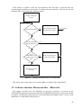
Software interface Microcontroller – Bluetooth...................................................46
5.2.1
BlueStack concept ............................................................................................47
5.2.2
Message sequence.............................................................................................47
6
CONCLUSION ...................................................................................................51
APPENDIX A ............................................................................................................52
APPENDIX B ............................................................................................................53
DOCUMENT REFERENCES ....................................................................................54
List of Figures
Figure 2-1: Layered structure of Profibus protocol architecture ................................................3
Figure 2-2: Hybrid access method to the common transmission medium at the Profibus .........5
Figure 2-3: IEC telegram (bottom) and structure of the embedded FDL telegram....................6
Figure 2-4: Waveform of the constant parts of the Profibus telegram (IEC telegram) ..............7
Figure 3-1: Bluetooth Protocol Stack as Specified by the Bluetooth SIG................................11
Figure 3-2: Piconets with a single slave operation (A), a multi-slave operation (B) and a
scatternet operation (C). ...................................................................................................13
Figure 3-3: Operating states in the Bluetooth system...............................................................15
Figure 3-4: Overview of the Lower Software Layers...............................................................16
Figure 3-5: HCI Command Packet ...........................................................................................17
Figure 3-6: HCI Event Packet ..................................................................................................18
Figure 3-7: L2CAP layer in the Bluetooth Protocol Architecture............................................18
Figure 3-8: Multiple emulation serial ports..............................................................................20
Figure 3-9: Multiplexer and Service Channels Relationship Example ....................................21
Figure 3-10: SDP Client-Server architecture............................................................................21
Figure 3-11: Service record ......................................................................................................22
Figure 3-12: Bluetooth Profiles Dependencies.........................................................................23
Figure 3-13: BCSP Context...................................................................................................... 27
Figure 3-14: ABCSP stack’s external interface........................................................................29
Figure 3-15: BlueStack protocol layers ....................................................................................31
Figure 3-16: BlueStack Integration ..........................................................................................32
Figure 3-17: Primitives with Layered Protocols ......................................................................33
Figure 3-18: Protocol message construction within a layered architecture..............................33
Figure 4-1: Hardware conception of PROFIBUS-Bluetooth monitoring module....................34
Figure 5-1: The hierarchical structure of program files ...........................................................40
Figure 5-2: Example of NRZ encoded data..............................................................................41
Figure 5-3: Example of the Manchester encoded data .............................................................42
Figure 5-4: Example of decoding from the Manchester code to the NRZ code.......................43
Figure 5-5: Waveform of Interrupt Service Routines...............................................................44
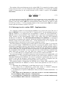
Figure 5-6: Block diagram of interrupt service routine ISR2...................................................46
Figure 5-7: Bluestack layers in the PROFIBUS-Bluetooth monitoring module ......................47
Figure 5-8: Message sequence chart for data link set up between two BlueCore devices .......50
List of Tables
Table 2-1: Basic characteristics of RS 485 transmission technology.........................................4
Table 2-2: Basic characteristics of IEC 1158-2 transmission technology..................................4
Table 2-3: Numeric values of constant parts of the Profibus telegram (IEC telegram) .............6
Table 2-4: Physical Profibus PA layer .......................................................................................8
Table 3-1: SDP Service record .................................................................................................25
Table 3-2: BCSP channels allocation .......................................................................................27
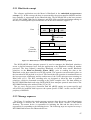
Table 5-1: Manchester encoding ..............................................................................................42
Table 5-2: The decoding rules ..................................................................................................43
1 Introduction
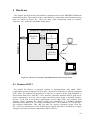
The main goal of this diploma thesis is the implementation of an interface between the
industrial communication technology PROFIBUS PA and the office radio technology
Bluetooth. This interface could be used for the remote monitoring of industrial devices.
This diploma thesis was created at the “Institut für Automation und Kommunikation e.V.
(ifak)”, Magdeburg, Germany. This institute executes the research based in the following
fields: automation, communications and sensors. The ifak has the certification laboratory for
PROFIBUS PA devices.
The Bluetooth radio technology presents a cheap and efficient solution for short-range
wireless data transfer. On the other hand, the PROFIBUS PA is a widespread data transfer
standard in the process automation. The conjunction of these two technologies presents a new
and easier option for the industrial data transfer. The advantages of this solution are the
connection and the devices’ monitoring without wires, and easy access toward the monitored
devices without complicated configuration of the attached monitoring devices such as PCs,
PDA and etc.
The realized interface module works as a monitoring slave device in the PROBIBUS PA.
That means the data is transferred only in one direction – from the PROFIBUS PA interface
to the Bluetooth interface.
The Bluetooth specification reduces all interactions between devices to a short-range, low
power, ad hoc wireless connection. The Bluetooth is a cable-replacement technology. From
whence it follows the main advantage of the Bluetooth technology - the connection without
wired link and without the proprietary connectors. The Bluetooth is mainly used in the
commercial sphere therefore the cost of a Bluetooth chip is very low. The next important
characteristic of Bluetooth chips is its low power consumption.
The low power consumption is very important requirement for all chips designed at the
interface module because the whole module is supplied from the PROFIBUS PA bus with the
limited supply.
For portability, the whole software was designed and developed in ANSI C language. Hence
the ANSI C Bluetooth protocol stack is applied. The Mezoe’s BlueStack was selected.
This document is structured to the four main chapters; Profibus (2), Bluetooth (3),
Hardware (4) and Software (5). The Profibus chapter describes the individual layers of
ISO/OSI model of PROFIBUS and a different version of PROFIBUS. The Bluetooth chapter
describes the Bluetooth specification, the main profiles, used BSCP host transport protocol
and the Mezoe’s BlueStack protocol stack. The Hardware chapter describes the main three
chips and how they work and cooperate in the interface module. The Software chapter
describes in detail the software application running on the microcontroller MSP430.
1
2 Profibus
2.1 Introduction
Profibus (PROcess FIeld BUS) is a fieldbus system, which is widespread all over the world.
All Profibus variants are based on the ISO/OSI reference model for communication networks
(2.2). Profibus was standardized in the German standard DIN 19 245. The research was
supported by German government in cooperation with automation manufacturers (Bosh and
Siemens). In March 1996, this standard was embedded into the European Fieldbus standard
EN 50170 Volume 2 without modifications. This guarantees stability and openness for users
and vendors worldwide. The Profibus devices from different manufacturers can communicate
without special interface adjustments.
Profibus is a vendor-independent, open fieldbus standard for a wide range of applications in
a manufacturing (e.g. automotive industries), a process control (e.g. chemical and
petrochemical industries) and a building automation (e.g. air condition, central heating). It can
be used for both high-speed time critical data transmission and extensive complex
communication tasks.
The Profibus distinguishes between the following types of devices:
•
Master devices (active stations, with bus access control) determine the data
communication on the bus. A master can send messages without an external request, when
it holds the bus access rights (the token). There are two types of master device,
class 1 master (DPM1) (is a central controller, e.g. a PLC or PC, which cyclically
exchanges data with the distributed stations (slaves) in a defined message cycle) and
class 2 master (DPM2) (configuration, diagnostic, monitoring and maintenance devices
using acyclic communication to communicate with other devices (class 1 master or
slaves)).
• Slave devices (passive stations, without bus access control) are peripherals such as I/O
devices, valves, drivers and measuring transducers. They have no bus access rights and
they can only acknowledge received messages or send a response message to the master.
2.2 ISO/OSI model
As indicated above, the Profibus is based on the layered ISO/OSI (International Standard
Organization/Open System Interconnection) communication model for open system
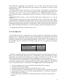
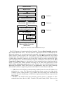
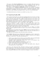
communication (refer to ISO 7498 standard). This specification defines 7 layers, but the
Profibus uses only 3 layers of them: Layer 1 (Physical Layer), Layer 2 (Data Link Layer) and
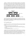
Layer 7 (Application Layer). The remaining layers (Layers 3 to 6) are empty to minimize
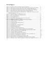
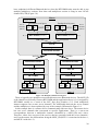
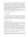
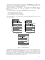
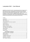
expense and increase efficiency (time reaction). The architecture is shown in the Figure 2-1.
• Physical layer (1st layer) defines the type of medium, including length and topology, the
line interface, the number of stations and the transmission speed, the electrical and the
mechanical characteristics (modulation, coding) (2.2.1).
• Data link layer (2nd layer) is responsible for the reliable data transfer via physical
medium, telegram structure, address and control of data flow. In Profibus, layer 2 is called
Fieldbus Data Link (FDL). It splits in two sub-layer: Medium Access Control (MAC) –
access on the common medium (Token Passing, Master-Slave) and LLC (Logical Link
Control) – telegram structure and control of data flow (2.2.2).
• Application layer (7th layer) presents the services for application (user) processes.
Application layer is only used in the FMS version of Profibus.
2
Application programs
DP
PA
FMS Profile
DP Profile
PA Profile
Layers
FMS
User
DP - extension
DP - basic functions
Application (7)
Fieldbus Message
Specification
(FMS)
(3) - (6)
Data Link (2)
Physical (1)
EN 50 170
Not used
Fieldbus Data Link (FDL)
RS-485 / Fiber Optical
IEC Interface
IEC 1158-2
PROFIBUS Profiles
Figure 2-1: Layered structure of Profibus protocol architecture
For additional information on ISO/OSI reference model, see [12].
2.2.1 Physical layer
The application area of a fieldbus system is largely determined by the choice of
transmission technology. As well as general demands made on bus system, such as high
transmission reliability, large distances and high transmission speed, in process automation
additional requirements must also be satisfied, such as operation in hazardous areas and
transmission of data and energy on a common cable. Since it is not possible to satisfy all
requirements with a single transmission technology, therefore exist three transmission
methods (physical profiles) available for Profibus:
•
1
2
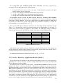
RS 485 (high speed - H2) is especially used for the Profibus DP/FMS. It covers all areas
in which a high transmission speed and simple, cost-effective installation are required. A
shielded twisted cooper cable with one conductor pair is used. It is a serial communication
interface. All devices are connected in a bus structure (parallel). The bus structure permits
addition and removal of stations or step-by-step commissioning of the system without
affecting the other stations. Later expansions have no influence on the stations, which are
already in operation. Transmission speed is available between 9.6 Kbps1 and 12 Mbps2.
One unique transmission speed is selected for all devices on the bus. The maximum cable
length depends on the transmission speed (higher speed (baud rate) = shorter cable length
Kbps – Kilobits per second
Mbps – Megabits per second
3
in the segment). Using repeaters can extend the cable length. Up to 32 stations (masters or
slaves) can be linked up in one segment. If there are more than 32 stations, repeaters must
be used to link up the individual bus segments. An active bus terminator at the start and
end of each segment terminates the bus. RS 485 uses asynchronous transmission with NRZ
coding; one character has 11 bits (1 start bit, 8 data bits, 1 even parity bit, 1 stop bit) [13].
Medium
Number of station
Transmission
Topology
Remote powering
shielded twisted pair cable
32 stations in each segment without repeater
9.6 Kbps to 12 Mbps; asynchronous NRZ coding
linear bus
power supply using a separate cable
Table 2-1: Basic characteristics of RS 485 transmission technology
•
IEC 1158-2 (low speed – H1) is a synchronous transmission with Manchester coding
(5.1.1.1.2) without mean values in accordance with IEC 1158-2 standard. Constant baud
rate of 31.25 Kbps is used in process automation. IEC 1158-2 applies the specifications of
the FISCO (Fieldbus Intrinsically Safe Concept) model for intrinsically safe operation. In
steady state, each station consumes a maximal basic current 10 mA. With bus powering,
this current serves the power supply to the field devices. The basic current is modulated by
the sending device in the range of ± 9 mA. Each segment has only one source of power, the
power supply unit. For an optimum electromagnetic compatibility (EMC), the bus lines
must be shielded. The bus line must be equipped with a passive line termination at both
ends. Since the electrical power in the segments is limited in explosion hazardous areas
due to intrinsic safety requirements, the number of connectable field devices is limited as
well. Depending on the explosion requirements and energy consumption of the devices, 10
(EEx) up to 32 (non-explosive) devices can be linked up in one segment [13].
Medium
Number of station
Transmission
Topology
Remote powering
twisted pair (shielded or unshielded)
32 stations in each segment without repeater
31.25 Kbps; synchronous Manchester coding
line, star and tree, or a combination
power supply using the bus cable
Table 2-2: Basic characteristics of IEC 1158-2 transmission technology
•
Fiber Optic conductors may be used in Profibus for application in environments with
very high electromagnetic interference, for electric isolation or to increase the maximum
network distance for high transmission speeds. Maximal length of bus depends on the type
of optical fiber (glass, synthetic) and can be extended up to 80 km range. Profibus segment
using fiber-optic technology are designed using either a star or a ring structure. Many
manufactures also offer couplers between RS 485 transmission links and optical fibers
[13].
2.2.2 Data link layer (Fieldbus Data Link)
2.2.2.1 Medium access protocol
All versions of Profibus use identical medium access protocol. This protocol is implemented
in layer 2 with correspondence to the ISO/OSI reference model. The Medium Access Control
(MAC) must ensure that only one station has the right to transmit data at the time.
4
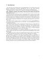
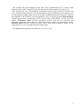
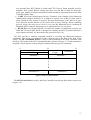
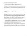
Profibus is a multi-master system and thus allows the operation of several automation,
engineering or visualization systems with their distributed peripherals on one common bus.
The hybrid bus access control system operates on the token passing method among the master
devices and uses the master-slave principle to communicate between master and slave
devices. The token passing procedure ensures that the bus access right (the token) is assigned
to each master within a precisely defined time frame. It allows him to have an exclusive
control over the communication network within that time frame. The token must be passed
around the logical token ring once to all masters (in order of increasing addresses) within a
maximum token rotation time. The master-slave procedure permits the master (the active
station) that currently owns the token to access the assigned slaves (the passive stations). This
enables the master to send the messages to, or to receive the response messages from the
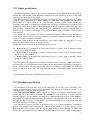
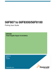
slaves (Figure 2-2).
Token Passing
Token
Master 1
Slave 1
Master 2
Slave 3
Master - Slave
Slave 2
Figure 2-2: Hybrid access method to the common transmission medium at the Profibus
When an active station receives the token telegram, it can communicate with all slave
stations in the master-slave communication relationship and all master stations in a mastermaster communication relationship that is supported only the Profibus FMS. During
operation, defective or switched-off active stations are automatically removed from the ring
and new stations are added to the ring [13].
2.2.2.2 Logical link control
This sublayer is responsible for a telegram structure. Profibus uses more types of telegrams
for optimal utilization transfer channel. The Fieldbus Data Link (FDL) defines the following
telegrams:
• telegrams without data field (6 control bytes) SDL = 10h
• telegrams with one data field of fixed length (8 data and 6 control bytes) SDL = A2h
• telegrams with a variable data field (0 to 244 data bytes and 9 to 11 control bytes)
SDL = 68h
• brief acknowledgement (1 byte)
• token telegram for bus access control (3 bytes) SDL = DCh
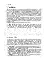
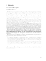
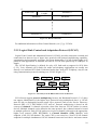
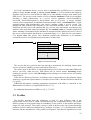
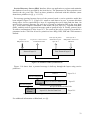
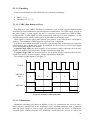
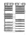
In Figure 2-3, the top part illustrates the structure of a FDL telegram with a variable data
field length. While the bytes of the FDL telegram are transmitted asynchronously in the form
of UART characters, the transmission on the IEC segments is bit synchronous. Here, the FDL
telegram is additionally supplied with the preamble and the start and end delimiters.
Each FDL frame (on Data Link Layer) consists of a Start Delimiter Data Link (SDL), an
Information Field and a Frame check sequence (FCS). The Information Field is divided into
an Address Field and a Control Field. Additionally, a Data Unit may exist [14].
5
On the Physical layer (2.2.1), the start of all IEC telegrams is marked by the preamble,
which is used for synchronization effect. The next mark is start delimiter, which represents a
start of FDL telegram, followed by itself FDL telegram. The IEC telegram is terminated by
the end limiter (Figure 2-3).
FDL Telegram
SDL
LE
LEr
SDL
DA
SA
FC
Data Unit
FCS
EDL
SDL: Start Delimiter Data Link FC: Frame control
LE-LEr : Length byte
FCS: Frame check sequence
DA: Destination address
EDL: End delimiter Data Link
SA: Source address
PREAMBLE
1 to 8 Bytes
START
DELIMITER
1 Byte
FDL TELEGRAM
1 to 256 Bytes
END
DELIMITER
1 Byte
IEC Telegram
Figure 2-3: IEC telegram (bottom) and structure of the embedded FDL telegram
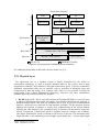
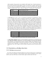
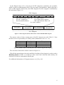
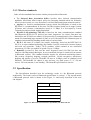
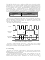
The numeric values of three constant parts of the IEC telegram are in the Table 2-3. Note
that the one bit is represented by two binary values (Manchester code 5.1.1.1.2).
Start Delimiter
End Delimiter
Preamble
Hexadecimal
B24D
B326
9999
Binary
10 11 00 10 01 00 11 01
10 11 00 11 00 10 01 10
10 01 10 01 10 01 10 01
Table 2-3: Numeric values of constant parts of the Profibus telegram (IEC telegram)
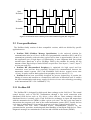
The waveform of these three marks is shown in Figure 2-4.
With all data transmissions, the parity and block checking of the telegrams is used to reach a
Hamming distance of HD = 4, so that up to three errors can be detected with certainty. All
characters of frame are transmitted without gaps.
For additional information on Telegram structure, see [12], p. 901.
6
Start
Delimiter
End
Delimiter
Preamble
Figure 2-4: Waveform of the constant parts of the Profibus telegram (IEC telegram)
2.3 User specifications
The Profibus family consists of three compatible versions, which are divided by specific
application area:
•
Profibus FMS (Fieldbus Message Specification) is the universal solution for
communication tasks at cell level. At this level programmable controllers (PLCs and PCs)
communicate primarily with each other (typical access time is approximately 100 ms). At
this application area a high degree of functionality is more important than fast system
reaction times. Baud rate is up to 500 Kbps. FMS is also suitable for transfer the big
amount of data. Physical layer can be RS 485 or optic fiber. Uses layers 1, 2 and 7, layers 3
to 6 are not used (2.2).
• Profibus DP (Decentralized Periphery) is optimized for high speed and low
connection costs and has been especially designed for communication between the
automation control systems (PLC) and distributed field devices (typical access time
<10 ms). It can be used for data capture from periphery devices (slaves) (2.3.1).
• Profibus PA has been specifically designed for process engineering. It permits the
linking of sensors and actuators to a common bus cable also in hazardous areas. It enables
the data communication and energy supply for devices in two-wire technology according
to the international IEC 1158-2 standard (2.3.2).
2.3.1 Profibus DP
The Profibus DP is designed for high-speed data exchange at the field level. The central
control devices, such as PLC/PC communicate through a fast serial connection with
distributed field devices such as I/O, drives, valves and etc. Data exchange with these
distributed devices is mainly cyclic. Each field device exchanges its input and output data
with the automation device (DPM1) within a given cycle time. The bus cycle time must be
shorter than the program cycle time of the central automation system (PLC). Usually the bus
cycle time is approximately 10 ms and the program cycle time is approximately 40 ms.
In addition, DP also offers extended acyclic communication services for the
parameterization, operation, monitoring and alarm handling of intelligent field devices. These
diagnostic messages are transmitted over the bus and collected at the master (DPM2).
7
The transmission technology can be RS 485 (2.2.1) or fiber optic with baud rate from
9.6 Kbps up to 12 Mbps. DP transmission time depends on the number of stations and the
transmission speed.
DP permits mono-master (one master is active on the bus) or multi-master (several masters
are connected to one bus. These master represent either independent subsystems, each
consisting of one class 1 master and its assigned slaves, or additional diagnostic devices –
class 2 masters) systems. A maximum 126 devices (masters or slaves) can be connected to
one bus.
The Profibus DP uses layers 1 and 2 from ISO/OSI reference model, layers 3 to 7 are not
used (2.2).
Data transmission between the master and the DP slaves is divided into three phases;
parameterization, configuration and data transfer. Before a DP slave enters the data transfer
phase, the master checks in the parameterization and configuration phase whether the planned
configuration matches the actual device configuration. In the course of this check, the device
type, format and length information, as well as the number of inputs and outputs must agree.
For additional information on Profibus DP, see [13].
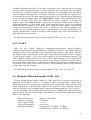
2.3.2 Profibus PA
The Profibus PA (Process automation) was mainly designed for applications in explosion
hazardous areas. It permits the linking of sensors and actuators to a common bus cable also in
hazardous areas. It enables the data communication and energy supply for devices in two-wire
technology according to the international standard IEC 1158-2 (2.2.2.1). The field devices in
the hazardous area are connected via Profibus using IEC 1158-2 transmission technology
(Table 2-4).
Transmission technique
Transmission rate
Intrinsic safety
Bus supply
IEC 1158-2
31.25 Kbps
optional
optional
Table 2-4: Physical Profibus PA layer
Unlike the automated applications in manufacturing engineering, which require short cycle
times of few milliseconds, other factors are of importance in process automation, such as
intrinsically safe transmission techniques, power supply of field devices over the bus cable,
reliable data transmission and interoperability (standardization of device functions).
The transition to the non-hazardous area, where Profibus is used with RS 485 technology, is
effected by a segment coupler or link (installed between DP and PA segment). From the point
of view of the bus protocol, it is transparent. The coupler assumes the following tasks:
•
•
•
•
electrical isolation between the safe and the intrinsically safe bus segment
powering of the PA bus segment
adaptation of transmission technique from RS 485 to IEC 1158-2
baud rate adaptation, if segment couplers are used, the baud rate in the RS 485 segment
is restricted to a maximum of 93.75 kbis/s (Pepperl&Fuchs) or 45.45 Kbps (Siemens) or
12 Mbps DP/PA Link (Siemens).
• conversion between asynchronous UART telegrams and synchronous 8-bit/character
telegrams
8
The Profibus PA data telegrams of the IEC 1158-2 transmission are to a large extent
identical with the FDL telegrams of the asynchronous RS 485 transmission (Figure 2-3).
The Profibus PA uses internationally recognized function block model to describe the
device functions and parameters. The function blocks represent different user functions, such
as analog input or analog output. Every device have minimum three blocks; physical, function
and transducer. These blocks can be imagined like parts of control program. Physical block
contains general device information such as device name, manufacture, version and serial
number. Transducer block contains application specific data such as correction and
calibration parameters and make the connection with actuators or measuring sensors.
Function block provides measured values, which come from transducer block, to the
connected bus or vice versa and checks the limit values.
For additional information on Profibus PA, see [13] or [14].
9
3 Bluetooth
3.1 General Description
3.1.1 Introduction
The Bluetooth is an open, low cost, low power radio based communications standard for
short range, point-to-multipoint voice and data wireless transfer. Bluetooth can transmit
through solid, non-metal objects. Its nominal link range is from 10 cm to 10 meters, but can
be extended to 100 meters by increasing the transmit power. It is based on short-range radio
links, and facilitates ad hoc connections for stationary and mobile communication
environments. It replaces the many proprietary cables that connect one device to another with
one universal short-range radio link.
Where did the Bluetooth name originally come from? It named after a Danish Viking and
King, Harald Blåtand (translated as Bluetooth in English), who lived in the latter part of the
10th century. Harald Blåtand united and controlled Denmark and Norway (hence the
inspiration on the name; uniting devices through Bluetooth).
Ericsson Mobile Communication started the work with development of Bluetooth in 1994.
The Institute of Electrical and Electronic Engineers (IEEE) has developed and approved a
new wireless standard, 802.15.1 that is fully compatible with Bluetooth. As with Bluetooth,
the new standard has a smaller transmission range and lower speed than the 802.11 standard,
although both standards run in the unlicensed ISM (Industrial Scientific Medicine) band at
2.4 GHz. The 802.15.1 standard is supported by the Bluetooth Special Interest Group (SIG).
Bluetooth technology has been designed to operate in noisy radio frequency environments,
and uses a short acknowledgement and fast frequency-hopping scheme to make the link
robust, communication wise. Compared with other systems operating in the same frequency
band, the Bluetooth radio typically hops faster and uses shorter packets. This is because short
packages and fast hopping limit the impact of microwave ovens and other sources of
disturbances.
Bluetooth is based on the IEEE 802.11 standard. This standard defines the protocol for two
types of networks; Ad-hoc and client/server networks:
•
An Ad-hoc network is a simple network where communications are established
between multiple stations in a defined coverage area, without the use of an access point or
server. The standard specifies the etiquette that each station must observe so that they all
have fair access to the share wireless media.
• The client/server network uses an access point that controls the allocation of transmit
time for all stations, and allows mobile stations to roam from cell to cell. The access point
routes data between the stations and other wireless stations or to and from the network
server.
Documentation on Bluetooth is split into two sections, the Bluetooth Specification (3.2) and
Bluetooth Profiles (3.3).
10
3.1.2 Wireless standards
Other wireless standards based on the similar principles like a Bluetooth:
•
The Infrared Data Association (IrDA) specifies three infrared communication
standards: IrDA-Data, IrDA-Control, and a new emerging standard called AIr. Primarily,
IrDA is point-to-point, it is very directional, it will not transcend opaque materials and etc.
• Airport is a wireless communications system, which, like Bluetooth, is based on the
IEEE 802.11 recommendation. It also uses 2.4 GHz frequency band, but its range is about
45 meters and it boasts a transmission speed of 11 Mbps. It is developed by Lucent
Technologies and used with Apples Macintosh.
• Wireless LAN-technology (WLAN) is based on the same communications standard
like Bluetooth (IEEE 802.11) and uses the same frequencies for carriers. But there the
similarities end. WLANs use ordinary LAN protocols for communication. Nor is Bluetooth
meant for transmitting huge amounts of data, as are LANs and WLANs. Bluetooth puts its
emphasis on dynamically handling mobile units of various kinds.
• Wi-Fi is the name of a similar, but simpler, technology, based on the IEEE 802.11b.
Wi-Fi is an open standard technology that enables wireless connectivity between laptops
and local area networks. Today's Wi-Fi products, which transmit in the unlicensed
spectrum at 2.5 GHz, are capable of speeds of up to 11 Mbps.
• HomeRF (version 2.0) also uses the same frequency band (2.4 GHz) but does not
interfere with Bluetooth technologies. It uses centralized concept (a central unit) in contrast
to Bluetooth (ad hoc). This standard includes support for advanced networking features
like security (frequency hopping, network password, 128-bit encryption), interference
dodging and quality of service. HomeRF 2.0 runs at 10 Mbps (same as standard wired
Ethernet). The HomeRF 2.0 chipset is tiny and uses very little power (3.3 V, 120 mA
receive, 250 mA transmit, 3 mA standby). The HomeRF specification is not free.
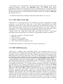
3.2 Specification
The Specification describes how the technology works (i.e. the Bluetooth protocol
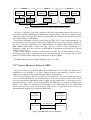
architecture). The actual version of Bluetooth specification is version 1.1. The layered model
of Bluetooth protocol stack is shown in the Figure 3-1 and briefly described in the next
sub-chapters.
RFCOMM
SDP
L2CAP
HCI
Link Manager
Baseband
Radio
Figure 3-1: Bluetooth Protocol Stack as Specified by the Bluetooth SIG
11
3.2.1 Radio specification
The Bluetooth Radio (layer) is the lowest defined layer of the Bluetooth specification. It
defines the requirements of the Bluetooth transceiver device operating in the 2.4 GHz ISM
(Industrial Scientific Medicine) band.
The Bluetooth radio accomplishes spectrum spreading by frequency hopping in 79 hops
(79 MHz range) displaced by 1 MHz, starting at 2402 MHz and finishing at 2480 MHz
(RF channels: f = 2402+k MHz, k = 0,…,78). In some countries (Spain, France, Japan) this
frequency band range is (temporarily) reduced, and a 23 hops (23 MHz range) system is used.
It should be noted that products implementing the reduced frequency band would not work
with products implementing the full band. The maximum frequency-hopping rate is
1600 hops/s (it is equal to slot length of 625 µs). It is enable high performance in noisy radio
environments.
The Bluetooth radio module uses GFSK (Gaussian Frequency Shift Keying) modulation
characteristic where a binary one is represented by a positive frequency deviation and a binary
zero by a negative frequency deviation.
Bluetooth radio modules avoid interference from other signals by hopping to a new
frequency after transmitting or receiving a packet.
The Bluetooth specification has defined three power levels:
•
Power Class 1 is designed for long-range devices (~100m), with a maximal output
power of 100 mW (20 dBm).
• Power Class 2 is designed for ordinary range devices (~10m), with a maximal output
power of 2.5 mW (4 dBm).
• Power Class 3 is designed for short-range devices (~10cm), with a maximal output
power of 1 mW (0 dBm).
The Bluetooth radio interface is based on a nominal antenna power of 0 dBm. Each device
can optionally vary its transmitted power. Bluetooth use a dynamical regulation of transmitted
power. At the master side the transmitted power is completely independent for different
slaves; a request from one slave can only affect the master’s transmitted power for that same
slave.
For additional information on Radio Specification, see [3], p. 15-32.
3.2.2 Baseband specification
The baseband is the physical layer of the Bluetooth. It provides error correction, flow
control, synchronization and security functions. The Bluetooth baseband protocol is a
combination of circuit and packet switching.
The Time-Division Duplex (TDD) scheme is used for full duplex transmission where
master and slave alternatively transmit. The channel is represented by a pseudo random
hopping sequence. On the channel, information is exchanged through packets. Each packet is
transmitted on a different hop frequency. The channel is divided into time slots, each 625 µs
in length (the hop frequency is 1600 hops/s). A packet nominally covers a single time slot, but
can be extended to cover up to five slots.
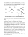
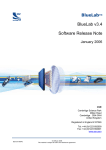
The Bluetooth system provides a point-to-point or a point-to-multipoint connection
(Figure 3-2). In the point-to-multipoint connection, the channel is shared among several
Bluetooth units. Two or more units sharing the same channel form a piconet. All Bluetooth
devices are peer units and have identical implementations. However, when establishing a
12
piconet, one unit will act as a master for synchronization purposes, and the other(s) as
slave(s). Up to seven slaves can be active in the piconet. Multiple piconets with overlapping
coverage areas form a scatternet. Each piconet can only have a single master. However,
slaves can participate in different piconets on a time division multiplex basis. In addition, a
master in one piconet can be a slave in another piconet. The piconets shall not be frequency
synchronized. Each piconet has its own hopping channel.
MASTER
A
B
SLAVE
C
Figure 3-2: Piconets with a single slave operation (A), a multi-slave operation (B) and a scatternet
operation (C).
Different types of physical links can be established between master and slave(s). The link
type defines what type of packets can be used on a particular link. Two link types have been
defined:
•
•
Synchronous Connection Oriented (SCO) link (used primarily for voice).
Asynchronous Connection Less (ACL) link (used primarily for packet data).
Different master-slave pairs of the same piconet can use different link types, and the link
type may change arbitrarily during a session. Each link type supports up to sixteen different
packet types. Four of these are control packets and are common for both SCO and ACL links.
The SCO link is a point-to-point symmetric link between a master and a single slave in the
piconet. The SCO link reserves slots at regular intervals and can therefore be considered as a
circuit-switched connection.
The ACL link is a point-to-multipoint packet oriented link between the master and all the
slaves participating on the piconet and supports both symmetric and asymmetric traffic. In the
slots not reserved for the SCO link(s), the master can establish an ACL link on a per slot basis
to any slave, including the slave(s) already engaged in an SCO link (packet switched type).
Up to three simultaneous synchronous voice channels, or a channel, which simultaneously
supports asynchronous data and synchronous voice can be used in Bluetooth. Each voice
channel supports a 64 Kbps synchronous (voice) channel in each direction. The asynchronous
channel can support maximal 723.2 Kbps asymmetric (and still up to 57.6 Kbps in the return
direction), or 433.9 Kbps symmetric in both directions.
Bluetooth has five logical channels, which can be used to transfer different types of
information. These channels are carried by SCO or/and ACL links.
Four possible types of addresses can be assigned to Bluetooth units. Each Bluetooth
transceiver is allocated a unique 48-bit Bluetooth device address (BD_ADDR). This 48-bit
address is divided into three fields:
13
•
•
•
LAP field: lower address part consisting of 24-bit
UAP field: upper address part consisting of 8-bit
NAP field: non-significant address part consisting of 16-bit
Each slave active in a piconet is assigned a 3-bit active member address (AM_ADDR)
(also called the MAC address). A slave only accepts a packet with a matching active member
address and broadcast packets (the all zero AM_ADDR). The active member address is only
valid as long as a slave is active on the channel. The master assigns the address to the slave
when the slave is activated.
A slave in park mode can be identified by its dedicated 8-bit parked member address
(PM_ADDR). When the slave is activated, it is assigned an active member address but loses
the parked member address.
The access request address (AR_ADDR) is used by the slave in the slave initiated unpark
procedure. This address is assigned to the slave when it enters the park mode and is only valid
as long as the slave is parked. The access request address is not necessarily unique; i.e.
different parked slaves may have the same access request address.
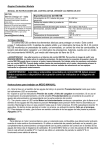
Bluetooth device operates in two major states: Standby (default state) and Connection.
There are seven sub-states, which are used to add slaves or make connections in the piconet.
These are page, page scan, inquiry, inquiry scan, master response, slave response and
inquiry response. Before any connections in a piconet are created, all devices are in Standby
mode. A connection is made by a Page message being sent if the Bluetooth device address is
already known, or by an Inquiry message followed by a subsequent Page message, if the
address is unknown. The inquiry procedure enables a device to discover which devices are in
range, and determine the addresses and clocks for these devices. With the paging procedure,
an actual connection can be established.
The Bluetooth device may leave the Standby state to scan for page or inquiry messages, or
to page or inquiry itself. When responding to a page message, the unit enters the Connection
state as a slave. When carrying out a successful page attempt, the unit will enter the
Connection state as a master (Figure 3-3).
The Bluetooth units can be in several modes of operation during the Connection state:
•
In the Active mode, the Bluetooth unit actively participates on the channel. The master
schedules the transmission based on traffic demands to and from the different slaves.
Active slaves listen in the master-to-slave slots for packets.
• In the Sniff mode, a slave device listens to the piconet at reduced rate (it listens only
every M slots). The sniff interval is programmable and depends on the application.
• In the Park mode, a device is still synchronized to the piconet but does not participate
in the traffic (have no active member address). Parked devices only occasionally listen to
the traffic of the master to re-synchronize, page messages and check on broadcast
messages. Instead of active member address (AM_ADDR), it receives two new addresses;
park member address (PM_ADDR) and access request address (AR_ADDR).
• Hold mode is a power saving mode that can be used for connected units in a piconet if
no data needs to be transmitted. The master unit can put slave units into HOLD mode,
where only an internal timer is running. Any device can wake up the link again, with an
average latency of 4 seconds. During the hold mode, the slave unit keeps its active member
address (AM_ADDR).
14
STANDBY
INQUIRY
PAGE
(unknown address)
(known address)
DATA
TRANSFER
CONNECTION
PARK
HOLD
SNIFF
Low Power Modes
Figure 3-3: Operating states in the Bluetooth system
For additional information on Baseband Specification, see [3], p. 33-181.
3.2.3 Link Manager Protocol (LMP)
The Link Manager Protocol (LMP) is used by the Link Managers for link set up, security
and control. The messages are filtered out and interpreted by Link Manager on the receiving
side and are not propagated to higher layers. To perform its service provider role, the LM uses
the services of the underlying Link Controller (LC). Link Manager messages have higher
priority than the user data.
At the link layer, the security is maintained by authentication (the process of verifying
'who' is at the other end of the link) of the peers and encryption of the information. For this
basic security, it is needed a public address, which is unique for each device (Bluetooth device
address), two secret keys (authentication keys and encryption key) and a random number
generator. After authentication, encryption may be used to communicate.
When two devices do not have a common link key, an initialization key (Kinit) is created
based on a PIN, a random number and a Bluetooth Device address. When both devices have
calculated Kinit the link key is created in the pairing procedure, and finally a mutual
authentication is made.
For additional information on Link Manager Protocol, see [3], p. 183-251.
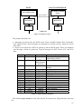
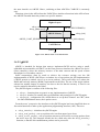
3.2.4 Host Control Interface (HCI)
The Host Controller Interface (HCI) provides a command interface to the Baseband Link
Controller and Link Manager, and access to hardware status and control registers. The HCI
exists across 3 sections; the Host, the Transport Layer and the Host Controller. Each of the
sections has a different role to play in the HCI system (Figure 3-4).
15
Bluetooth Host
Higher Layer
HCI Driver
Software
Physical Bus Driver
Physical Bus
(USB, UART,…)
Firmware
Physical Bus Firmware
Hardware
HCI Firmware
Link Manager
Firmware
Baseband Controller
Bluetooth Host Controller
(Hardware)
Figure 3-4: Overview of the Lower Software Layers
The HCI Firmware is located on the Host Controller. The term Host Controller means the
HCI-enabled Bluetooth device. The HCI firmware implements the HCI Commands for the
Bluetooth hardware by accessing baseband commands, link manager commands, hardware
status registers, control registers, and event registers. The term Host means the HCI-enabled
Software Unit. The Host will receive asynchronous notifications of HCI events independent
of which Host Controller Transport Layer is used. HCI events are used for notifying the Host
when something occurs. The Host and Host Controller communicate each other via the Host
Controller Transport Layer (i.e. physical bus). These intermediate layers should provide the
ability to transfer data without intimate knowledge of the data being transferred. Several
different Host transport protocols can be used, of which 3 have been defined initially in the
Bluetooth specification: USB, UART, RS 232 and additional to these, the CSR (Cambridge
Silicon Radio) defined a proprietary protocol called BlueCore Serial Protocol (BCSP).
•
USB (Universal Serial Bus) communications standard comes from the PC industry. Its
architecture is a tree. The Bluetooth specification always assumes the high speed,
12 Mbps version. USB provides a very reliable link with strong error detection and
recovery. The main disadvantage of USB is the implementation difficulty compared with
other options.
• RS 232 is the UART based host transport protocol requires a minimum of three
communication lines; Receive (RX), Transmit (TX) and Ground (GND). There are also
16
two optional lines; RTS (Ready to Send) and CTS (Clear to Send) normally used for
hardware flow control. Before sending any bytes over the RS 232 link, the baud rate,
parity type, number of stop bit and protocol mode should be negotiated between the Host
Controller and the Host.
• UART (Universal Asynchronous Receive Transmit) is the simplest of the Bluetooth
standard host transport protocols. It is defined to operate over an RS 232 link with no
parity. Hardware flow control is required. The huge disadvantage with UART is its poor
error detection and the absence of any useful error recovery strategy. When something
does go wrong, the only way to recover is to reset the Bluetooth device, breaking all
Bluetooth links. It may be cheap and easy to implement, but it is not robust.
• BCSP (BlueCore Serial Protocol) overcomes the number of limitations posed by the
USB, RS 232 and UART. BCSP is designed to simplify the RS 232 protocol that has a
major impact on RAM. It is described in the special section (3.4).
The HCI provides a uniform command method of accessing the Bluetooth hardware
capabilities. The results of commands will be reported back to the Host in the form of the
events. The HCI Command Packet is used to send commands to the Host Controller from
the Host. The format of the HCI Command Packet is shown in Figure 3-5. Each command is
assigned a 2 byte Opcode used to uniquely identify different types of commands.
0
16
OpCode
OCF
OGF
31
Parameter Total
Lenght
Parameter 0
Parameter 1
Parameter ….
Parameter N-1
Parameter N
Figure 3-5: HCI Command Packet
The HCI Event Packet is used by the Host Controller to notify the Host when events occur
(Figure 3-6).
17
0
16
Parameter Total
Lenght
Event Code
31
Parameter 0
Parameter 1
Parameter ….
Parameter N-1
Parameter N
Figure 3-6: HCI Event Packet
For additional information on Host Control Interface, see [3], p. 535-826.
3.2.5 Logical Link Control and Adaptation Protocol (L2CAP)
Logical Link Control and Adaptation Protocol (L2CAP) provides connection oriented and
connection less data services to upper layer protocols with protocol multiplexing capability,
segmentation and reassembly operation, and group abstractions. L2CAP permits higher-level
protocols and applications to transmit and receive L2CAP data packets up to 64 Kbytes in
length.
The L2CAP Specification is defined for only ACL links and no support for SCO links
(3.2.2). Voice channels (SCO links) for audio and telephony applications are usually run
directly over baseband SCO links. Packetized audio data, such as IP Telephony, may be sent
using communication protocols running over L2CAP (Figure 3-7).
SDP
RFCOMM
LMP
TCS
L2CAP
ACL
BASEBAND
AUDIO
VOICE
SCO
Figure 3-7: L2CAP layer in the Bluetooth Protocol Architecture
L2CAP must support protocol multiplexing because the Baseband Protocol (3.2.2) does
not support identification of the higher layer protocols being multiplexed above it. L2CAP
must be able to distinguish between upper layer protocols such as the Service Discovery
Protocol SDP (3.2.7), RFCOMM (3.2.6) and etc. Protocol multiplexing is based on the
concept of channels. A channel represents a data flow between L2CAP entities in remote
devices. Multiple channels can be bound to the same protocol, but a channel cannot be bound
to multiple protocols. Each L2CAP packet received on a channel is directed to the appropriate
higher level protocol (SDP, RFCOMM). A Channel identifier (CID) identifies each
endpoint of the L2CAP channel. The same CID is not reused as a local L2CAP channel
endpoint for multiple simultaneous L2CAP channels between a local device and some remote
18
device. The device can assign CIDs independently from other devices. Channels may be
connection oriented or connection less.
An L2CAP implementation segments higher layer packets into chunks that can be passed to
the Link Manager via the Host Controller Interface (HCI) where they will be converted into
Baseband packets. On the receiving side, an L2CAP implementation receives chunks from the
HCI and reassembles those chunks into L2CAP packets using information provided through
the HCI and from the packet header. The Segmentation and Reassembly (SAR)
functionality is absolutely necessary to support protocols using packets larger than those
supported by the Baseband protocol (3.2.2).
In the concept of data packet format is used the term Protocol/Service Multiplexer (PSM).
The PSM value must be odd. Also, all PSM values must be assigned such that the least
significant bit of the most significant octet is zero. The PSM value definition is specific to
L2CAP and is assigned by the Bluetooth SIG. The PSM values are separated into two ranges.
Values in the first range are assigned by the Bluetooth SIG and indicate (target) protocols
(0x0001 - Service Discovery Protocol, 0x0003 - RFCOMM, [3], p 280). The second range of
values are dynamically allocated and used in conjunction with the Service Discovery Protocol
(SDP) (3.2.7).
For additional information onL2CAP, see [3], p. 253-330.
3.2.6 RFCOMM
The RFCOMM is a simple transport protocol, which provides emulation of RS 232 serial
ports (9 circuits) over the L2CAP protocol. RFCOMM layers communicate with each other
through the use of frames and these frames make up the data payload of a L2CAP packet. The
RFCOMM protocol is based on the ETSI standard TS 07.10. Only a subset of the TS 07.10
standard is used, and in addition some adaptations of the protocol are specified in the
Bluetooth RFCOMM specification.
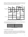
The RFCOMM protocol supports up to 60 opened emulated ports between two Bluetooth
devices. The port instance is identified by the Data Link Connection Identifier (DLCI). The
DLCI usable value range for ports is 2 to 61. The DLCI is unique within one RFCOMM
session between two devices. To account for the fact that both client and server applications
may reside on both sides of an RFCOMM session and are able to independently make
connections with respect to each other, the DLCI value space is divided between the two
communicating devices using the concept of RFCOMM server channels and a direction bit
D (DLCI = D + Server Channel). Server channel is an association between an application
(service) and a logical ID in RFCOMM. Server applications registering with an RFCOMM
service interface are assigned a Server Channel number in the range 1…30. This server
channel should be registered in the Service Discovery Database (3.2.7), allowing remote
devices to locate, and connect to the application.
For an RFCOMM session, the initiating device (the device which setting up RFCOMM
channel on L2CAP and starting RFCOMM multiplexing) is given the direction bit D = 1 (and
conversely, D = 0 in the other device). As a consequence, server channel 1 on the initiating
device becomes DLCI 3, and server channel 1 on the other device becomes DLCI 2 and so on.
In other words, server applications (it is an application that awaits a connection from an
client on another device) on the non-initiating device are reachable on even values of DLCI
(2, 4 ,6 ,…, 60); and server applications on the initiating device are reachable on the odd
values of DLCI (3, 5, 7,…, 61). Note that for a device that supports multiple simultaneous
RFCOMM sessions to two or more devices, the direction bit might not be the same on all
sessions.
At any time, there must be at most one RFCOMM session between any pair of devices. If a
Bluetooth device supports multiple emulated serial ports and the connections are allowed to
19
have endpoints in different Bluetooth devices, then the RFCOMM entity must be able to run
multiple multiplexer sessions. Note that each multiplexer session is using its own L2CAP
channel ID (CID) (Figure 3-8).
Master
Application
Emulated serial ports
1
30
2
(2)
(60)
(4)
Server
channels
(DLCI)
D=0
Emulated serial ports
Server
1
30
2
channels
(3)
(61) (DLCI)
(5)
RFCOMM (session 1)
RFCOMM (session 2)
CID 1
CID 2
D=1
L2CAP
Baseband & Radio
RADIO
RADIO
Baseband & Radio
Baseband & Radio
L2CAP
L2CAP
RFCOMM
1
30
2
(3)
(61)
(5)
Emulated serial ports
Application
D=1
D=0
RFCOMM
1
30
2
(2)
(60)
(4)
Emulated serial ports
Slave 1
Slave 2
Figure 3-8: Multiple emulation serial ports
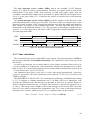
There is logically one multiplexer associated between two Bluetooth devices. The MUX_ID
is the identifier used locally between RFCOMM and the application above it. It is assigned by
RFCOMM, usually as a result of the RFC_Start_Req primitive (3.5). Each multiplexer
instance supports one or more server channels. The relationship between the server channel
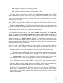
and the multiplexer is best explained by way of the example, illustrated in Figure 3-9.
In this example there is a master device communicating with two slaves. The master device
has two server channels that correspond to specific applications. There is a one-to-one
correspondence between a multiplexer instance (identified by a MUX_ID) and a slave.
Therefore, either slave can access the services that are associated with the server channels 1
and 2 on the master, the differentiator being the MUX_ID (MUX 1 is associated with slave 1,
and MUX 2 with slave 2).
20
Master
Slave 1
Server
channel 1
Server
channel 2
MUX 1
MUX 2
Server
channel 1
Slave 2
Server
channel 2
Server
channel 1
MUX 1
Server
channel 2
MUX 2
Figure 3-9: Multiplexer and Service Channels Relationship Example
The device opening up the first emulated serial port connection between two devices is
responsible for first establishing the multiplexer control channel. The device closing the last
connection (DLC) on a particular session is responsible for closing the multiplexer by closing
the corresponding L2CAP channel.
Wired ports commonly use flow control such as RTS/CTS to control communications. On
the other hand, the flow control between RFCOMM and the lower layer L2CAP depends on
the service interface supported by the implementation. In addition RFCOMM has its own
flow control mechanisms. Credit base flow, the one of flow control mechanism is a
mandatory feature that did not exist in RFCOMM in Bluetooth specifications v1.0B and
earlier [1] p. 415-419.
If all L2CAP channels towards a certain device are idle for a certain amount of time, a
decision may be made to put that device in a low power mode (i.e. use hold, sniff or park
mode). This will be done without any interference from RFCOMM.
For additional information on RFCOMM, see [8], p. 393-424.
3.2.7 Service Discovery Protocol (SDP)
The Service Discovery Protocol (SDP) allows Bluetooth devices to discover what services
(applications) are available, or to find a Bluetooth device that supports a specific service
without previous knowledge of the Bluetooth address of that device.
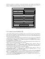
The Service Discovery Protocol is client-server architecture. The server maintains a list of
service records that describe the characteristics of services associated with the server. Each
service record contains information about a single service (application). A client may retrieve
information from a service record maintained by the SDP server by issuing an SDP request
(Figure 3-10). There is a maximum of one SDP server per Bluetooth device (if a Bluetooth
device acts only as a client then needs no SDP server). A single Bluetooth device may
function both as an SDP server and as an SDP client.
Client
Application
Server
Application
SDP REQUEST
SDP Client
SDP Server
SDP RESPONSE
Figure 3-10: SDP Client-Server architecture
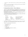
21
All of the information about a service that is maintained by an SDP server is contained
within a single service record. A service record handle is a 32-bit number that uniquely
identifies each service record within an SDP server (each handle is unique only within each
SDP server). The service record consists of a list of service attributes. Each service attribute
describes a single characteristic of a service (service attributes: ServiceClassIDList,
ServiceID, ProtocolDescriptorList, ServiceName and etc. [3] p.366). A service attribute
consists of two components; an attribute ID and an attribute value. An attribute ID is a 16-bit
unsigned integer that distinguishes each service attribute within a service record. The
attribute ID also identifies the semantics of the associated attribute value. A service class
definition specifies each of the attribute IDs for a service class and assigns a meaning to the
attribute value associated with each attribute ID. The attribute value is a variable length field
whose meaning is determined by the attribute ID associated with it and by the service class of
the service record in which the attribute is contained (Figure 3-11). Each service is an instance
of a service class. The service class definition provides the definitions of all attributes
contained in service records that represent instances of that class.
Service Record Handle
Service record
SERVICE ATTRIBUTE 1
SERVICE ATTRIBUTE 2
SERVICE ATTRIBUTE 3
SERVICE ATTRIBUTE 4
Service attribute
ATTRIBUTE ID
ATTRIBUTE VALUE
SERVICE ATTRIBUTE N
Figure 3-11: Service record
The service discovery protocol does not provide a mechanism for notifying clients when
service records are added to or removed from an SDP server.
The whole point of the SDP is to allow Bluetooth devices to discover what other Bluetooth
devices can offer (what services). SDP allows this in various means. Searching means
looking for specific service, while Browsing means looking to see what services are actually
being offered.
In the Service Discovery Protocol, an attribute value is represented as a data element. A data
element is a typed data representation. It consists of two fields: a header field and a data field
([3] p.349).
Additional information regarding application interaction with SDP is contained in the
Bluetooth Service Discovery Application Profile (3.3.3).
For additional information on SDP, see [3], p. 331-392.
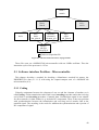
3.3 Profiles
The Profiles describe how the technology is used (i.e. how different parts of the
specification can be used to fulfill a desired function for a Bluetooth device). The profile
defines options in each protocol that are mandatory for the profile. It also defines parameter
ranges for each protocol. The profile concept is used to decrease the risk of interoperability
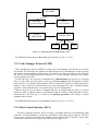
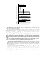
problems between different manufacturers' products. In Figure 3-12, the Bluetooth profile
structure and the dependencies of the profiles are depicted. A profile has dependencies on the
22
profile(s) in which it is contained – directly and indirectly. For example, the Object Push
profile is dependent on Generic Object Exchange, Serial Port, and Generic Access profiles. A
number of additional Bluetooth profiles are currently in the development.
Generic Acces Profile
Service Discovery App. Profile
PAN Profile
TCS-BINARY Based Profiles
Audio/Video Remote Control
Profile
Common ISDN Access Profile
Intercom Profile
Cordless Telephony Profile
Serial Port Profile
Headset Profile
LAN Profile
Dial-up Networking Profile
SIM Access Profile
Fax Profile
Hands-Free Profile
Generic Object Exchange Profile
File Transfer Profile
Synchronization Profile
Object Push Profile
Basic Imaging Profile
Basic Printing Profile
Figure 3-12: Bluetooth Profiles Dependencies
3.3.1 Generic Access Profile (GAP)
This profile defines the generic procedures that can be used for discovering identities,
names and basic capabilities of other Bluetooth devices that are in a mode where they can be
discoverable. Essentially this profile describes how the lower layers (LMP and Baseband) are
used, along with some higher layers.
For the descriptions in this profile of the roles that the two devices involved in a Bluetooth
communication can take, the generic notation of the A-party (the paging device in case of
link establishment, or initiator in case of another procedure on an established link) and the Bparty (paged device or acceptor) is used.
Bluetooth devices that do not conform to any other Bluetooth profile shall conform to this
profile to ensure basic interoperability and co-existence.
With respect to inquiry procedure (3.2.2), a Bluetooth device shall be either in
non-discoverable mode or in a discoverable mode (limited discoverable and general
discoverable mode). The device shall be in only one mode at a time. When a Bluetooth device
is in the non-discoverable mode it does not respond to inquiry.
With respect to paging procedure (3.2.2), a Bluetooth device shall be either in
non-connectable mode or in connectable mode. When a Bluetooth device is in the
non-connectable mode it does not respond to paging.
With respect to pairing procedure (3.2.3), a Bluetooth device shall be either in non-pairable
mode or in pairable mode. In pairable mode the Bluetooth device accepts paring (i.e.
creation of bonds) initiated by the remote device, and in the non-pairable mode it does not.
The purpose of the link establishment procedure is to establish a physical link (of ACL
type) between two Bluetooth devices.
23
The purpose of the channel establishment procedure is to establish a Bluetooth channel (a
logical link) between two Bluetooth devices. Channel establishment starts after link
establishment is completed when the initiator sends a channel establishment request
The purpose of the connection establishment procedure is to establish a connection
between applications on two Bluetooth devices. Connection establishment starts after channel
establishment is completed, when the initiator sends a connection establishment request
(initialization of RFCOMM and establishment of DLC in the case of a Serial Port Profile).
For additional information on Generic Access Profile, see [10], p. 13-62.
3.3.2 Serial Port Profile (SPP)
The Serial Port Profile defines the requirements for Bluetooth devices necessary for setting
up an emulated serial cable connections using RFCOMM between two peer devices. The
scenario covered by this profile is the setting up virtual serial ports on two devices and
connecting these with Bluetooth, to emulate a serial cable between the two devices. Any
legacy application may be run on either device, using the virtual serial port as if there were a
real serial cable connecting the two devices (with RS 232 control signaling).
Only one connection at a time is dealt with in this profile (only point-to-point
configurations). However, multiple executions of this profile should be able to run
concurrently in the same device. In this profile, only connection-oriented channels shall be
used. This implies that broadcasts will not be used in this profile.
This profile is built upon the Generic Access Profile (3.3.1), see Figure 3-12. All the
mandatory/optional requirements defined in Generic Access Profile are mandatory/optional
for this profile.
The following roles are defined for this profile: Initiator is the device that takes initiative to
form a connection to another device; Acceptor is the device that waits for another device to
take initiative to connect.
The application layer procedures in the Serial Port Profile are following:
The Establish Link and Set up Virtual Serial Connection procedure (supported by
Initiator) refers to performing the steps necessary to establish a connection to an emulated
serial port in a remote device. The steps in this procedure are:
1. Submit a query using the Service Discovery Protocol SDP to find out the RFCOMM
Server channel number of the desired application in the remote device.
2. Optionally, require authentication of the remote device to be performed. Also
optionally, require encryption to be turned on.
3. Request a new L2CAP channel to the remote RFCOMM entity.
4. Initiate an RFCOMM session on the L2CAP channel.
5. Start a new data link connection DLC on the RFCOMM session, using the
aforementioned server channel number.
After step 5, the virtual serial cable connection is ready to be used for communication
between applications on both sides. If there already exists an RFCOMM session between the
devices when setting up a new data link connection, the new connection must be established
on the existing RFCOMM session (This is equivalent to skipping over steps 3 and 4 above).
24
The Accept link and establish virtual serial connection procedure (supported by
Acceptor) refers to taking part in the following steps:
1. If requested by the remote device, take part in authentication procedure and upon
further request, turn on encryption.
2. Accept a new channel establishment indication from L2CAP.
3. Accept an RFCOMM session establishment on that channel.
4. Accept a new data link connection on the RFCOMM session.
The Register Service record in local Service Discovery Protocol SDP database
procedure (supported by Acceptor) refers to registration of a service record for an emulated
serial port in the SDP database. All services (applications) reachable through RFCOMM need
to provide an SDP service record that includes the parameters necessary to reach the
corresponding service (application), see 3.3.3.
There are no SDP Service Records related to the Serial Port Profile in Initiator. In the
Table 3-1 is described the Serial Port related entries in the SDP database of Acceptor. To
retrieve the service records in support of this profile, the SDP client entity in Initiator
connects and interacts with the SDP server entity in Acceptor via the SDP procedures.
Item
ServerClassIDList
ServiceClass0
ProtocolDescriptionList
Protocol0
Protocol1
ProtocolSpecificParametr0
ServiceName
Definition
Attribute ID
0x0001
0x0004
L2CAP
RFCOMM
Server Channel
Display Text name
Table 3-1: SDP Service record
Only Initiator may inquire and page within the execution of this profile. The paging step
will be skipped in Initiator when execution of this profile begins when there already exists a
baseband connection between Initiator and Acceptor.
For additional information on Serial Port Profile, see [8], p. 172-193.
3.3.3 Service Discovery Application Profile (SDAP)
This profile defines the protocols and procedures that shall be used by a service discovery
application on a device to locate services in other Bluetooth devices using the Bluetooth
Service Discovery Protocol (SDP).
The following roles are defined in this profile: A Local device (LocDev) is the device that
initiates the service discovery procedure. This device contains the service discovery
application used by a user to initiate discoveries and display the results of these discoveries. A
Remote Device (RemDev) is any device that participates in the service discovery process by
responding to the service inquiries generated by a Local Device. A Remote device contains a
service records database. The Local or Remote role assigned to a device is neither permanent
nor exclusive. A device could be a Local for a particular SDP transaction, while at the very
same time be a Remote for another SDP transaction. The service discovery user application in
a local device (LocDev) interfaces with the Bluetooth SDP client to send service inquiries and
receive service inquiry responses from the SDP servers of remote devices (RemDevs).
25
The scenarios covered by this profile are the following:
•
•
•
Search for services by service class - searching for known services
Search for services by service attributes - searching for specific services
Service browsing - general service search
Service discovery can be initiated by either a master or a slave device at any point for which
these devices are members of the same piconet. Also, a slave in a piconet may possibly
initiate service discovery in a new piconet, provided that it notifies the master of the original
piconet that it will be unavailable (possibly entering the hold operational mode) for a given
amount of time.
For additional information on Service Discovery Application Profile, see [8], p. 63-98.
3.4 BCSP (BlueCore Serial Protocol)
3.4.1 Introduction
BCSP (BlueCore Serial Protocol) is a proprietary host transport protocol used on CSR’s
(Cambridge Silicon Radio) BlueCore Bluetooth chips. It can be considered an alternative to
the two host transport protocols (UART, RS 232) defined in the Bluetooth Specification v1.1
(2.2.1). It operates over an RS 232 physical link, but hardware flow control is optional. BCSP
has its own different methods for detecting errors. The BCSP is used to control and format
information that flows between a Bluetooth Host and a Bluetooth Host Controller. An
instance of the BCSP runs on both the Host and the Host Controller.
Higher layers of the stack can be built upon the two-datagram services (Figure 3-13):
•
One bi-directional reliable datagram stream (with 16 channels) - messages are
repeatedly sent until the peer acknowledges reception. It is possible to use windowing
mechanism (sequence and acknowledge numbers).
• One bi-directional unreliable datagram stream (with 16 channels) - messages are sent
to the peer once. This type of message is naturally suited for SCO links.
Datagram passed through BCSP carry a 4-bit protocol identifier, so this effectively gives
16 channels of each type (the channel identifier zero must not be used by code above BCSP,
thus code above BCSP sees 15 channels of each type). Protocol identifier is used to multiplex
16 parallel bi-directional message channels across a single UART link. The whole channels
allocation is shown in Table 3-2.
26
HOST
HOST CONTROLLER
Rest of Host system
Rest of Host Controller
system
BCSP Channels
15+15
15+15
BCSP Stack
BCSP Stack
UART
UART
UART Link
Figure 3-13: BCSP Context
The primary data flows are:
•
Messages sent down into the BCSP stack. These normally include HCI Commands,
ACL and SCO data. These messages are translated to a stream of bytes, which are sent to
the UART.
• Bytes received from the UART are passed up into the BCSP stack. These are translated
into messages, which are passed up. Typical messages are HCI Events, ACL and SCO
data.
Channel
Reliable
0
Not Available
1
Unused
2
BCCMD
3
4
5
6
7
8
9
10
11
12
13
14
15
HQ
DM
HCI cmd/evt
HCI ACL
HCI SCO
L2CAP
RFCOMM
SDD
Reserved
DFU
VM
Unused
Reserved
Unreliable
Notes
Not Available Used internally by BCSP for
acknowledge packets.
BCSP Link
Establishment
Protocol
Unused
BlueCore Command Interpreter
channel
Unused
Host Query channel
Unused
Device Manager
Unsued
HCI commands and events
Unused
HCI ACL data
HCI SCO
HCI SCO data
Unused
Unused
Unused
Unused
Unused
Device Firmware upgrade
Unused
Virtual Machine
Unused
Reserved
Table 3-2: BCSP channels allocation
The following byte format is used: One start bit, Even parity bit, Eight data bits, One stop
bit.
27
To convert the RS 232 byte stream into a BCSP packet stream, a version of the SLIP
(described in internet standard RFC 1055) packet framing is implemented. The principle is to
surround each packet with a start and an end special byte (0xC0). This allows the beginning
and the end of a packet to be found and consequently the length of the packet to be known.
BCSP uses only one packet type. Each BCSP packet includes a four-byte header and a
payload that can contain 0 up to 4095 bytes. The Packet structure is described in detail in [1].
Before any transmission begins, a Link Establishment procedure enforces synchronization
without hardware flow control lines. Link establishment is based on two basic messages
SYNC / SYNC_RESPONSE and CONF / CONF_RESPONSE. These messages are sent
unreliably. The purpose of the link establishment is to know if the other device is ready to
communicate and to determine in which state it is [1], [7].
BlueCore chips (Bluetooth chips produced by CSR) contain dedicated hardware to improve
performance when using BCSP. In addition, BlueCore chips have hardware support for two
methods of reducing power consumption when the chip is idle: Shallow Sleep (current
consumption to 2 mA) and Deep Sleep (current consumption to 100 µA)
For additional information on BCSP, see [1].
3.4.2 Porting BCSP
The generic BCSP host stack consumes too much RAM (Random Access Memory) for use
in small, embedded applications. Hence, CSR provides other BCSP implementations
optimized for different applications: µBCSP (micro BCSP), ABCSP (Another BCSP) and
YABCSP (Yet Another BCSP). The all BCSP stacks are provided with ANSI C source codes.
With firmware RFCOMM1.1v13.10.5 Build 339 (BCSP interface) on the Host controller
side, it can be used all implementations of BCSP (generic BCSP, ABCSP, YBCSP, µBCSP)
on the Host side
3.4.2.1 ABCSP and YABCSP
ABCSP(Another BlueCore Serial Protocol) [5] is optimized to limit the RAM usage and
can work with small memory pool buffers. The penalty for this is that it uses more processing
power. ABCSP is good for embedded applications where RAM usage is important and will, if
sufficient processing power is available, provide good throughput.
The ABCSP library must first be initialized by a call to abcsp_init().To send a message,
higher layer code calls abcsp_sendmsg(); this places the message into a queue within the
library. The message includes HCI commands, ACL data or SCO data. The higher layer code
then repeatedly calls abcsp_pumptxmsgs() to translate the message into its BCSP wire format
and push these bytes out of the bottom of the library via ABCSP_UART_SENDBYTES().
For inbound messages the UART driver code passes BCSP wire format bytes into the
library via calls to abcsp_uart_deliverbytes(). When the library has all of the bytes to form a
complete higher layer message it calls ABCSP_DELIVERMSG() to pass this to higher layer
code.
In the Figure 3-14, function names in lower case are part of the library code. Function
names in upper case are macros within the code. The external environment must implement
these according to definitions given in ABCSP source header files.
YABCSP (Yet Another BlueCore Serial Protocol) [6] is optimized to limit the processing
power requirements. The penalty for the optimization is that it uses more and larger chunks of
RAM than ABCSP. YABCSP supports multiple instances. YABCSP was written with almost
28
the same interface as ABCSP. Hence, switching to/from ABCSP to YABCSP is extremely
easy.
Functions given in the API to/from the YABCSP are similar to functions in the API to/from
the ABCSP extended about the pointer to a specific instance.
Higher Layers
abcsp_sendmsg()
abcsp_pumptxmsg()
ABCSP_DELIVERMSG()
ABCSP Library
ABCSP_UART_SENDBYTES()
abcsp_init()
abcsp_uart_deliverbytes()
UART Driver
UART
Figure 3-14: ABCSP stack’s external interface
3.4.2.2 µBCSP
µBCSP is intended for designs that want to implement BCSP and are using a small,
embedded microcontroller unit (MCU) as the Host processor interfaced to a BlueCore device
(Host controller), where the memory resource is the main concern and the speed of data
throughput is of secondary concern.
Some compromises must be made to achieve the resource savings over the full
implementation of BCSP. µBCSP uses a window size of one packet (the full implementation
of BCSP permits a window size of up to seven packets). The overall effect is to reduce the
RAM and read only memory (ROM) requirements on the Host. The use of the single window
scheme has another impact on memory size due to the fact that the memory is fixed it can
now be statically allocated by the linker.
The µBCSP engine is consists of the following files:
•
•
•
ubcsp.c - functions that are generic to any implementation of µBCSP.
ubcsp.h - header file contains the type definitions and prototypes for µBCSP engine.
ubcspcfg.h - configuration file, which allows to set up these features: use CRC, show
the link establishment states, show packet errors.
From the users’ perspective the interface to the µBCSP engine has been simplified down to
four main functions to make up the application-programming interface (API). These are:
•
•
•
ubcsp_initialize() - initializes the µBCSP engine
ubcsp_send_packet() - sets up a packet to be sent from upper layer down
ubcsp_receive_packet() - sets up a packet structure to be used for receiving packets from
the lower layer up. This function should also be called only after the ubcsp_initialize()
function, so that the link establishment packets can be processed.
29
•
ubcsp_poll() - allows the upper layer stack to control the execution of the µBCSP
engine.
The get_uart() and put_uart() functions are system specific and will need to be modified
with respect to the system specific UART.
For additional information on µBCSP, see [4].
3.5 Bluetooth Protocol Stack – Mezoe’s BlueStack
BlueStack is a software implementation in ‘C’ of the Bluetooth protocol stack, as shown in
Figure 3-15. BlueStack introduces the Device Manager DM. This provides a number of stack
management functions, such as security management, and allows access to the HCI command
and event interface. The terms ‘Top’ and ‘Bottom’ are used to distinguish between the HCI on
the Host and on the Host Controller.
The BlueStack is accessible via BlueStack API (Application Programming Interface). The
BlueStack API is defined as a set of message primitives.
A service primitive takes the form in software of a structure; for example: the RFCOMM
primitive RFC_START_REQ has the following structure:
typedef struct
{
rfc_prim_t
type;
BD_ADDR_T
bd_addr;
psm_t
psm_remote;
SYS_PAR_T
sys_pars;
phandle_t
respond_phandle;
} RFC_START_REQ_T;
/* Always RFC_START_REQ */
/* Bluetooth device address */
/* psm of remote device */
/* System parameters */
/* Reply phandle (overides dflt is set) */
The primitive types are defined in the header file that describes the interface to the module,
in this example it would be RFCOMM and the header file is rfcomm_prim.h [9], p. 72-107.
BlueStack is supplied with the following elements:
•
•
•
•
•
•
•
•
Device Manager (DM)
SDP (3.2.7)
RFCOMM (3.2.6)
TCS
L2CAP (3.2.5)
HCI Top (3.2.4)
HCI Upper Driver (UART, RS 232 or BCSP)
Scheduler services
30
Application
Hardware
Dependent
SDP
RFCOMM
TCS Binary
Hardware Independent (Sourcecode available)
Integration Layer
L2CAP API
L2CAP
Device Mgr. API
Device Mgr.
HCI API
HCI Top
HCI Upper Driver
HCI Lower Driver
HCI Bottom
Link Manager
Link Controller
BASEBAND and Radio
Figure 3-15: BlueStack protocol layers
HCI Bottom and the Link Manager have been implemented to the BlueCore single chip
device from Cambridge Silicon Radio.
RFCOMM is a profile specific layer (Serial Port Profile). For example, when developing a
Bluetooth cordless telephone, TCS binary would be used as the profile specific layer, and not
RFCOMM. TCS Binary is a protocol that provides support for cordless telephony
functionality over the Bluetooth air interface.
As a software component, BlueStack requires integrating with other software to realize a
complete product. This software may be an existing application, or a completely new
application. The integration of existing application can be carried out in an Integration layer,
which sits between the application and BlueStack. When the application is wholly new, the
application could be designed to interface directly to the RFCOMM API (without Integration
layer).
The exact integration approach taken also depends on the type of product being developed.
There are three categories of products that designers might consider (Figure 3-16):
•
two-processors standard solution involving a Host and Host controller, where the
higher layers have to be ported to and implemented on the Host, where the physical split
between higher and lower layers of the stack takes place at the HCI (for example, a
PC-based application).
• two-processors embedded solution, where the split between a Host and a Host
controller does not take place at the HCI This allows products to be designed, where the
Host is resource limited (for example, an embedded host with limited resources, such as a
mobile phone).
• wholly embedded single processor solution, where there is no external Host processor,
for example a wireless headset.
31
There is no direct API provided for the control of the Link Manager from the application.
Control of the Link Manager from the application may be achieved indirectly using the HCI
calls that are available via the Device Manager API.
BlueStack is designed to work with all of the Bluetooth specified HCI host transport
protocols. HCI commands and events are accessible via the Device Manager
API [9], p. 293-301.
The interface associated with the Device Manager DM supports the following:
•
•
•
HCI Commands and Events (DM_HCI_)
Security Manager primitives (DM_SM_)
Device Manager private primitives (DM_)
The information on the full set of primitives is contained in the header files dm_prim.h and
hci.h [9], p. 219-288.
Application
RFCOMM SDP
L2CAP
Host
Host
Integration Layer
DM
RFCOMM SDP
HCI
Link Manager
Link Controller
BASEBAND and RF
Host Controller
HCI
Host Controller
Application
Integration Layer
L2CAP
DM
HCI
Link Manager
Link Controller
BASEBAND and RF
Standart two-processor
architecture
Embedded two-processor
architecture
Application
Application Interface
RFCOMM SDP
L2CAP
DM
HCI
Link Manager
Link Controller
BASEBAND and RF
HW
Wholly-Embedded single
processor architecture
Figure 3-16: BlueStack Integration
Service Discovery Client (SDC) Interface provides service-searching functions for the host
application. The parameters for these primitives are listed in the sdc_prim.h file. The
parameters include pointers to data describing the search patterns and attribute lists for
services being searched for. Both search patterns and attribute lists are formatted as the data
element sequences, as described in [8] p.349. There are seven basic primitives associated with
this interface (more about these primitives in [9], p 111).
32
Service Discovery Server (SDS) Interface allows an application to register and maintain,
the database of services provided by the local device. The parameters for these primitives are
listed in the sds_prim.h file. There are three primitives associated with this interface (more
about these primitives in [9], p. 111-132).
For message passing between layers of the protocol stack a service primitive model has
been adopted (Figure 3-17). If layer N+1 wants to send data to its peer, it presents this data
along with a service request REQ to layer N, requesting the service that sends the data. On
arrival of the protocol message, the peer layer N sends an indication IND to the peer layer
N+1. In the most complete realization of the model, the peer layer N+1 responds with RES
(RSP), and this result in a protocol message sends to protocol layer N. Finally, protocol layer
N sends a confirmation CFM to Layer N+1. The result of the service request is recorded in a
parameter in the CFM. Not all service primitives have REQ, RES, IND and CFM structures
defined.
Layer N+1
REQuests a service
Layer N+1 is sent a service
confirmation CFM
Peer layer N passes
INDication to peer
layer N+1
Protocol layer N
Peer layer N+1
RESponds to the service
indication
Peer Protocol layer N
Communication link
Figure 3-17: Primitives with Layered Protocols
Figure 3-18 shows how a protocol message is built up through the layers using service
primitives.
DATA
Layer N+1
Layer N Service Data Unit
Layer N
Service Request
Service Request
Layer N
Header
Layer N Protocol Data Unit
Layer N-1
Header
Layer N-1 Service Data Unit
Layer N-1
Figure 3-18: Protocol message construction within a layered architecture
For additional information on BlueStack, see [9].
33
4 Hardware
This chapter briefly describes the hardware components used at the PROFIBUS-Bluetooth
monitoring module. The concept of three main hardware components and interaction among
them are shown in Figure 4-1. There are many other components (such as resistors,
capacitors, etc.), which are not shown at this figure.
Profibus PA - Bluetooth Interface
VBUS+
PROFIBUS PA
VBUS-
SIEMENS
SIM 1
TxE, TxS
TI
RxA, RxS MSP430F148
UART
MITSUMI
WML-C06
Hand held computer
Bluetooth
Laptop computer
Figure 4-1: Hardware conception of PROFIBUS-Bluetooth monitoring module
4.1 Siemens SIM 1
For simple I/O devices, a practical solution is implementation with single ASICs
(Application Specific Integrated Circuit) chips. All protocol functions are already integrated
in the ASIC. No addition microprocessor or software is required. In the implementation of
bus-powered field device with IEC 1158-2 interface, particular attention must be paid to low
power consumption. As a rule, only a supply current less than 10 mA is available for these
devices. To be able to meet these requirements, special chips SIM 1 are available from
Siemens. SIM 1 (Siemens IEC MAU) enables the construction of a Fieldbus Medium
Attachment Unit (MAU) for 31.25 Kbps according to IEC 1158-2 standard (2.2.1) with only a
few external components. This chip can take the required operating energy from the
IEC 1158-2 bus connection or from external power supply and make it available as a supply
voltage for the other electronic components of the PA device.
34
The SIM1 contains a standard signal interface:
•
•
•
•
TxS (Transmit) Signal Input
TxE (Transmit Enable) Input for enabling the sender
RxS (Receive Signal) Receiver output
RxA (Receive Activity) Output for display of line activity
The SIM 1 supports 3 Operating Modes:
•
Bus powered, constant current consumption (Constant Current Mode CCM) The bus
is loaded with a constant current. The constant current can be set within the 4 mA up to
40 mA range. This mode is used in the PROFIBUS-Bluetooth monitoring module.
• Bus powered, constant power consumption (Constant Power Mode CPM) The voltage
drop is held constant.
• Locally powered (Local Power Mode LPM) In this mode the SIM 1 is locally powered
by a 5 V supply. The device doesn’t consume any current from the bus.
For additional information on SIM 1, see [10] and [11].
4.2 Texas Instruments MSP430F148
The MSP430 microcontrollers achieve maximum code efficiency with its ultra low power,
16-bit RISC architecture. The maximal external crystal frequency, which can be used, is
8 MHz. That determines 125 ns Instruction Cycle Time (ICT). Typically only register
instructions take 1 instruction cycle; other instructions take up to 6 cycles (depending on the
addressing modes of the operands). The instruction set consists of 24 core instructions and
27 emulated instructions with three formats and seven address modes. The MSP430x14x
series are microcontroller configurations with two built-in 16-bit timers, a fast 12-bit A/D
converter, two universal serial synchronous/asynchronous communication interfaces
(USART), and 48 I/O pins (six 8-bit ports). The specific version MSP430F148, which is used
in this PROFIBUS-Bluetooth monitoring module has 48 KB + 256 B Flash Memory and
2KB RAM available.
A clock distribution block allows the three clock sources (LFXT1, XT2, and DCO) to be
connected to the three internal clocks (ACLK, MCLK, and SMCLK) in a wide range of
configurations.
There are six 8-bit I/O ports implemented - ports P1 through P6. Every I/O pins are
individually configurable for input or output direction, and each I/O line can be individually
read or written. Interrupt processing of external events is fully implemented for all eight bits
of ports P1 and P2 (two interrupt vectors). Each interrupt for the P1 and P2 I/O lines can be
individually enabled and configured to provide an interrupt on a rising or falling edge of an
input signal.
For additional information on microcontroller MSP430, see [23] or [24].
4.2.1 Timer
There are two build-in timers in the microcontroller. The Timer_A module offers one 16-bit
counter and three capture/compare registers. The Timer_B module offers one configurable
(16-, 12-, 10-, 8-) bit counter and seven capture/compare registers. The function of Timer_B
35
is slightly different from Timer_A. The timer clock source can be selected from two external
sources or from two internal sources (ACLK or SMCLK). The clock source can be divided by
one, two, four, or eight. The timer can be fully controlled - it can be halted, read, and written;
it can be stopped, run continuously, or made to count up or up/down using one compare block
to determine the period. The three capture/compare blocks are configured by the application
to run in capture or compare mode. The capture mode is mostly used to individually measure
internal or external events from any combination of positive, negative, or positive and
negative edges. The compare mode is mostly used to generate timing for the software or
application hardware, or to generate pulse width modulated output signals. An individual
output module is assigned to each of the three capture/compare registers. Two-interrupt
vectors are used by this module. One vector is assigned to first capture/compare block
(CCR0), and one common-interrupt vector is implemented for the timer and the other two
capture/compare blocks. The three-interrupt events using the same vector are identified by an
individual interrupt vector word.
For additional information on microcontroller MSP430 Timer, see [23], p.151–185.
4.2.2 USART
There are two USART (Universal Synchronous/Asynchronous Receive/Transmit)
peripheries implemented in the MSP430x14x: USART0 and USART1. The USART supports
synchronous SPI and asynchronous UART communication protocols. This chapter discusses
the operation of the asynchronous UART mode. Two dedicated interrupt vectors are assigned
to each USART module - one for the receiving and one for the transmitting channels. The
UART character format consists of a start bit, seven or eight data bits, an even/odd/no parity
bit, an address bit (in address-bit mode), and one or two stop bits. The bit period is defined by
the selected clock source and set up the baud rate registers. The maximum USART baud rate
is one-third of the UART source clock frequency. The transmitting and receiving functions
use the same baud rate frequency.
For additional information on microcontroller MSP430 Timer, see [23], p.227-257.
4.3 Mitsumi’s Bluetooth module WML–C06
Wireless communication module based on CSR’s BlueCore01 chip and conforming to
Bluetooth Specification Version 1.1. It includes a radio chip BlueCore01, external Flash
ROM and antenna on a single module. The BlueCore01 chip together with an external Flash
ROM containing the CSR Bluetooth software stack provides a fully compliant Bluetooth
system for data and voice communications. It supports communication up to 10 m (class II).
There are enabled UART (asynchronous serial interface), USB, PCM and SPI (synchronous
serial interface) interfaces at this module. The parameters of the Mitsumi’s Bluetooth module
WML-06 are following:
Bluetooth frequency
Number of channels
Power supply voltage
Current Consumption
Maximum Data Rate
2402 up to 2480 MHz
79 channels
3 ± 0.1 V
max. 80 mA
Asynchronous: 723 Kbps / 57.6 Kbps
Synchronous: 433.9 Kbps / 433.9 Kbps
36
The firmware can be downloaded to the Flash ROM memory through the SPI (Serial
Peripheral Interface) interface with BlueFlash utility. The PSTool utility allows
programming of BlueCore's persistent store keys over SPI interface too. The Persistent Store
(PS) Keys are necessary for configuration the BlueCore01 chip. Briefly description of each of
the Persistent Store keys is in [20]. BlueFlash and PSTool utilities are members of BlueSuite
Development tool [21].
For additional information on Mitsumi’s Bluetooth module WML–C06, see [15].
4.3.1 CSR’s BlueCore01 chip
BlueCore01 is a true single chip for the Bluetooth (2.4 GHz), implemented in CMOS
technology. On the BlueCore01 chip runs a 16-bit RISC microcontroller with XAP2
architecture. All memory is 16-bit wide at this architecture. The XAP2 has no 8-bit type. The
XAP2 architecture cannot address the byte stored in the high half of a memory location. A
consequence of this is that sizeof(uint16) and sizeof(uint8) return the same value on the XAP2
architecture (i.e., 1). For more information on XAP2 architecture, see [18] and [19].
Signals UART_TX, UART_RX, UART_RTS, and UART_CTS form a conventional
asynchronous data serial interface. This interface is programmable with these parameters:
•
•
•
•
•
Baud rate: selectable; 115200 bps (default)
Data bits: 8 bits
Parity: ON or OFF (default)
Stop bits: 1 bit (default) or 2 bits
Flow Control: RTS/CTS (default) or none
For additional information on CSR’s BlueCore01 chip, see [16] and [17].
4.3.2 RFCOMM Firmware
BlueCore01 is supplied with a Bluetooth software stack firmware that runs on its
microcontroller and is resident in the (external) Flash memory. In general there are two forms
of firmware release available from CSR. These firmware releases are based on splits in the
Bluetooth protocol stack. The usual split is at the HCI or RFCOMM level and therefore the
two firmware releases available are known as either the HCI firmware or the RFCOMM
firmware builds. This section describes the fundamentals of an RFCOMM firmware build.
In the PROFIBUS-Bluetooth monitoring module is used RFCOMM1.1v13.10.5 firmware.
RFCOMM indicates that this is an RFCOMM variant of firmware; 1.1 indicates that this
release supports the Bluetooth Specification version 1.1; v13.10.5 indicates that this firmware
is based upon the HCI Stack1.1v13.10 firmware build and that this is the fifth (.5) build based
upon this firmware. Two variants of this firmware are provided; the first supports the BCSP
(Blue Core Serial Protocol) transport protocol (Build ID = 339 or 341) and the second
supports the Bluetooth UART (Universal Asynchronous Receiver Transmitter) protocol
(Build ID = 340 or 342). Each variant is available in versions that support both 56 and 128-bit
encryption. Build IDs and identifier strings can be checked using the PSTool utility or
BlueFlash utility available from CSR. RFCOMM bandwidth is limited to approximately
360 Kbps. The default Persistent Store settings are optimized for point-to-point applications,
such as headset or cable-replacement. In this release, the on-chip RFCOMM buffer size is
approximately 750 bytes. For frame-sizes of less than 370 bytes, it is possible to fit two or
more frames in the buffer simultaneously. The Host can therefore transfer a packet over BCSP
37
while BlueCore01 transmits a packet over the radio. At frame-sizes greater than 370 bytes, it
is only possible to fit a single frame into the buffer, and the host must wait for the frame to be
transmitted over the radio before transferring another frame over BCSP.
The RFCOMM firmware gives the application programming interface (API) access to the
RFCOMM layer, L2CAP layer, SDP and device manager. Direct access to the HCI layer is
prohibited when an RFCOMM firmware build is used. Some HCI commands and events are
accessible via the Device Manager API.
For additional information on this version of RFCOMM firmware, see [22].
38
5 Software
The software application can be split into the two sub-programs. The first subprogram
(5.1) is a software interface between the output of SIM 1 (the PROFIBUS PA data) and the
I/O port of microcontroller MSP430. The second subprogram (5.2) is a software interface
between the UART interface of microcontroller MSP430 and the UART interface of
Bluetooth device BlueCore01. The common element of these two subprograms is a data
buffer. The first subprogram decodes the incoming PROFIBUS data and writes them to this
common data buffer. The second subprogram forms an RFCOMM link between two
Bluetooth devices and then passes data from the common data buffer between them.
There are the header and C source files used in the software application, which runs on the
PROFIBUS-Bluetooth monitoring module. The following files need to be compiled and
linked together. The hierarchical continuity among the files is shown at the Figure 5-1.
•
main.c – C Source file containing the main functions, which associate PROFIBUS
(res1.c) and Bluetooth (blue.c) parts.
• main.h - Header file contains application specific definitions and prototypes for main.c.
• Dtypes.h – Header file contains the type definitions used in the “ifak” company.
• types.h - Header file contains the general type definitions.
•
blue.c – C Source file joins the primitives from files below and establish, maintenance
and close the Bluetooth link.
• blue.h – Header file contains the type definitions and prototypes for blue.c source file.
• bluetoot.h - Header file contains the Bluetooth specific type definitions.
•
•
dm.c – C Source file contains the access to BlueStack device manager primitives.
dm.h - Header file contains dedicated device manager specific definitions and
prototypes for dm.c source file.
• dm_prim.h - Header file defines device manager primitive definitions and messages.
•
hci.h - Header file contains HCI definitions and messages.
•
•
rfcomm.c – C Source file contains the access to BlueStack RFCOMM layer primitives.
rfcomm.h - Header file contains dedicated RFCOMM layer specific definitions and
prototypes for rfcomm.c source file.
• rfcomm_p.h - Header file defines RFCOMM layer primitive definitions and messages.
•
•
sdp.c – C Source file contains the access to BlueStack service discovery primitives.
sdp.h - Header file contains dedicated service discovery specific definitions and
prototypes for sdp.c source file.
• sdc_prim.h - Header file defines SDP layer primitive definitions and messages.
•
res1.c – C Source file contains PROFIBUS interrupt service routines and hardware
initialization functions for whole PROFIBUS-Bluetooth monitoring module.
• res1.h – Header file contains the type definitions and prototypes for res1.c source file.
•
•
•
ubcsp.c - C Source file for the µBCSP engine.
ubcsp.h - Header file contains the type definitions and prototypes for µBCSP engine.
ubcspcfg.h - Header file for configuring the µBCSP engine.
39
main.c
main.h
blue.c
blue.h
hci.h
dm.c
dm.h
dm_prim.h
res1.c
res1.h
rfcomm.c
rfcomm.h
rfcomm_p.h
sdp.c
sdp.h
sdc_prim.h
ubcsp.c
ubcsp.h
ubcspcfg.h
Hardware dependent file
Figure 5-1: The hierarchical structure of program files
These files runs on a MSP430F148 microcontroller with an 8 MHz oscillator. Thus the
instruction cycle of the processor is 125 ns.
5.1 Software interface Profibus – Microcontroller
This chapter describes a method for decoding a Manchester encoded bit stream- the
PROFIBUS PA data (5.1.1.1.2) with using the capture/compare unit of a MSP430F148
microcontroller (4.2).
5.1.1 Coding
Uniquely assignment between the elements of one set and the elements of another set is
called coding. At the transmission end of link is used encoding procedure and at the receiving
end of link is used decoding procedure of transfer data. Uncoded data signal is not suitable
for direct transfer via data channel (e.g. includes DC component). There is the next problem
with synchronization between the transmission and receiving end of transfer link at the
uncoded signal. The encoding is the result for addition the synchronization and rejection of
DC component of signal.
40
5.1.1.1 Encoding
In the next subchapters are described these two encoding technology:
•
•
NRZ (5.1.1.1)
Manchester (5.1.1.1.2)
5.1.1.1.1 NRZ (Non Return to Zero)
Non-Return to Zero (NRZ) encoding is commonly used in slow speed communications
interfaces for both synchronous and asynchronous transmission. The NRZ signal belongs to
the polar signals. A polar signal may have a two-state (non-return-to-zero (NRZ)) binary
coding scheme. A polar signal is usually symmetrical with respect to zero amplitude, i.e., the
absolute values of the positive and negative signal states are nominally equal.
NRZ signal is without spaces and without zero polarity (only with positive and negative
polarity). The advantage of NRZ signal is rejection of DC component.
A problem arises when using NRZ to encode a synchronous link, which may have long runs
of consecutive bits with the same value. It is difficult for the receiver to recover clock signal
and to distinguish one bit from another.
In positive-logic NRZ, the more negative or less positive voltage represents the low state,
and the less negative or more positive voltage represents the high state.
In negative-logic NRZ, the more positive or less negative voltage represents the low state,
and the less positive or more negative voltage represents the high state.
The example of NRZ signal is in Figure 5-2.
CLOCK
ORIGINAL
DATA
1
0
0
1
1
0
+a
NRZ DATA
-a
Figure 5-2: Example of NRZ encoded data
5.1.1.1.2 Manchester
Manchester encoding (also know as Biphase Code) is a synchronous (the receiver uses a
clock which is synchronized to the transmitter clock) encoding technique used to combine
data and clock signals to form a single self-synchronizing data bit stream. A Manchester
encoded signal contains frequent level transitions, which allow the receiver to extract the
41
clock signal (this allows the receiver to synchronize with the sender) and correctly decode the
value and timing of each bit. In this technique, the actual binary data to be transmitted over
the link are not sent as a sequence of logic 1's and 0's (known as Non Return to Zero (NRZ)
5.1.1.1.1). Instead, the bits are translated into a slightly different format following the rules
described in the Table 5-1. Logic 0 is indicated by a 0 to 1 transition (rising edge) at the
center of the bit and logic 1 is indicated by a 1 to 0 transition (falling edge) at the center of the
bit. Note that the signal transitions do not always occur at the bit boundaries (the division
between one bit and another), but that there is always a transition in the middle of each bit.
Original Data
Locic 0 (LOW)
Logic 1 (HI)
Sending Data
0 to 1 (upward transition at bit centre)
1 to 0 (downward transition at bit centre)
Table 5-1: Manchester encoding
There are two bits of Manchester encoded data for each bit of original data. The penalty for
doing this is Manchester encoded data consumes more bandwidth than original data in NRZ
code. Zero DC component of serial bit stream and simple error detection are the main
advantages of using Manchester encoding.
The example of Manchester Encoding is shown at Figure 5-3.
CLOCK
ORIGINAL
DATA
1
0
0
1
1
0
MANCHEST
ER DATA
Figure 5-3: Example of the Manchester encoded data
Given that a 0 encodes to 01 and 1 encodes to 10, it follows that 00 and 11 are illegal
sequences. These codes are used to the data error check. The illegal code is used as a unique
start/stop pattern to identify the boundaries of data frame as well.
5.1.1.2 Decoding
This chapter only describes the decoding technology, which is used for decoding from the
Manchester code (5.1.1.1.2) to the NRZ code (5.1.1.1.1). The same way (direction) is used in
the PROFIBUS-Bluetooth monitoring module.
For correct decoding is necessary to set the width of one bit Ti at the first time. The
Manchester encoding splits each bit period into two, and ensures that there is always a
transition between the signal levels in the middle of each bit. That means one bit of
42
Manchester code includes two different levels. Whence it follows that one bit must be read
twice per period. The optimal way is read the samples in the ¼ and ¾ of bit’s width Ti. The
initial sample is set at the ¾ Ti and next samples are read with distance of ½ Ti. The whole
principle of decoding from Manchester to NRZ is shown in Figure 5-4.
Sample
points
Bit period Ti
+a
MANCHESTER
DATA
-a
3/
4
1/
Ti
Ti
2
1
0
0
1
1
0
1
0
1
NRZ DATA
Figure 5-4: Example of decoding from the Manchester code to the NRZ code
The rules for decoding are summarized in Table 5-2. There are two adjacent values of an
one bit of Manchester signal read in the ¼ Ti and ¾ Ti in the first column. There are
corresponding values of NRZ in the second column.
Two samples of Manchester
01
10
00
11
One bit of NRZ
0
1
undefined (illegal code)
undefined (illegal code)
Table 5-2: The decoding rules
5.1.2 Interrupt service routines
Decoding (5.1.1.2) from the Manchester code, which is used at the PROFIBUS PA bus, to
the NRZ code has two distinct phases, synchronization to the bit period and then sampling of
the data bits. For this reason there are defined two interrupt service routines. These interrupt
service routines never work all at once. The interaction of these two interrupt service routines
with the PROFIBUS’s telegrams is shown in the Figure 5-5.
43
The first interrupt service routine (ISR1) detects the preamble of IEC telegram
(Figure 2-3), which is used for synchronization. The timer in a capture mode is used for the
measurement of the pulse width. After detection of eight same pulses (these form the
preamble) is calculated the sample time as a one half of a pulse width. The first sample time is
set to ¾ of the pulse width (5.1.1.2) and then the control is passed to the second interrupt
routine ISR2.
The second interrupt service routine (ISR2) reads the samples of the data bits in the
predefined sample time, which was set by ISR1. The timer works in a compare mode. After
detection of start delimiter of IEC telegram the data bits are read in the sample time and then
these samples are written to the common data buffer. The data from this data buffer is
transmitted via the Bluetooth interface (5.2). The procedure of decoding is explained in the
section 5.1.1.2. After detection of end limiter of IEC telegram the control is passed back to the
first interrupt routine ISR1.
ISR2
ISR1
Profibus PA Preamble
SD
FDL
ED
Preamble
SD
FDL
ED
Figure 5-5: Waveform of Interrupt Service Routines
5.1.3 Time calculation
The second interrupt service routine ISR2 is time critical. Its maximal runtime is 13.875 µs
that represents maximal 37 assembler instructions. The explanation of this result is given in
this section.
An enter to the interrupt service routine takes 6 cycles, further it must be allowed for up to
6 cycles in addition to complete the current instruction. Return from interrupt service routine
takes 5 cycles. So even an empty interrupt service routine (with no instructions) requires up to
17 cycles that means 2.125 µs (17x125 ns).
One instruction takes from 1 cycle up to 6 cycles, that means approximately 3 processor
cycles per instructions. This three instruction cycles represent 375 ns (TINST) (3x125 ns) with
8 MHz’s oscillator.
The PROFIBUS PA with the IEC 1158-2 transmission technology with Manchester coding
(5.1.1.1.2) supports a constant transmission rate 31.25 Kbps. One bit of Manchester code
includes two different levels and therefore one bit must be read twice per period. Whence it
follows a double transmission rate - 62.5 Kbps. This baud rate is equal to the period of 16 µs
(TSAMPLE). This time presents a length of the second interrupt service routine ISR2. From the
period of 16 µs must be subtracted the maintenance time TINTR (enter to and return from the
interrupt service routine), which presents 2.125 µs (explained above in this section).
TISR2 = TSAMPLE – TINTR = 16 µs - 2.125 µs = 13.875 µs
(5.1)
44
The runtime of the second interrupt service routine ISR2 (TISR2) must be less than or equal
to the period of 13.875 µs. If one instruction takes approximately 375 ns then the maximal
number of instructions per the second interrupt service routine is equal to 37 assembler
instructions.
TISR2 13.875 µs
=
= 37
TINST
375 ns
(5.2)
At the selected microcontroller MSP430F148, the first interrupt service routine ISR1 is no
time critical, but the second interrupt service routine ISR2 is time critical. In practice, the
runtime of the first routine ISR1 (the synchronization routine) must be less than or equal
to 29.875 µs (31.25k(-1) - 2.125 µs) and the runtime of the second routine ISR2 (the sample
routine) must be less than or equal to 13.875 µs.
5.1.4 Interrupt service routine ISR2 – Implementation
Two compilers suitable for microcontroller MSP430 were used in this work. The one of
them is MSPGCC. It is a port of the GNU C Compiler (GCC) for the embedded processor
MSP430. MSPGCC is a completely free and unlimited C compiler for Texas Instruments’s
MSP430 series of microcontrollers. The compiled source code can be downloaded over the
JTAG interface to the microcontroller using C-Spy utility from the IAR Embedded
Workbench for MSP430. The IAR Embedded Workbench for MSP430 is an integrated
development environment with compiler, download and debug utilities and is not free. Two
limited versions exist for this software tool - version limited in the size of compiled code
(maximum 4 kB) or time limited version (30 days evaluation version).
The block diagram of interrupt service routine ISR2 is shown in the Figure 5-6. In the first
step is read the sample of PROFIBUS bit and this is saved in the global variable. Then is
checked the terminating sequences (end delimiter data link EDL, maximal telegram length or
wrong telegram). When the terminating sequence is detected, the parameters for interrupt
service routine ISR1 are set and the control is switched into it. On the other hand is checked if
the start delimiter data link SDL is occurred. After detection of start delimiter is checked if the
whole NRZ byte is already read. One NRZ byte contains 16 bits of Manchester code
(5.1.1.1.2). If the NRZ byte is completed then it is saved to the common data buffer.
The theoretical number of assembler instructions in the interrupt service routine ISR2 is 37
instructions (5.1.3). The practical number depends on the used compiler (MSPGCC or IAR
Embedded Workbench for MSP430), the level of optimisation (optimisation for size or for
speed of code) and the debugger’s option (debug or release version of compiled code; the
debug version adds some instructions for debugging to the compiled code).
The practical number of instructions for interrupt service routine ISR2 compiled by IAR
Embedded Workbench for MSP430 in release version and optimized for size of code is
following:
• odd sample bits of Manchester’s coded data stream is read – 32 instructions.
• even sample bits of Manchester’s coded data stream is read(two subsequent
Manchester’s bits are decoded to one NRZ bit) – 36 instructions.
• one NRZ bytes (is equal to16 Manchester’s bits) is written to common data buffer – 32
instructions.
• odd sample bits of Manchester’s coded data stream is read and simultaneously
the start delimiter SDL is detected – 38 instructions.
• even sample bits of Manchester’s coded data stream is read and simultaneously
the start delimiter SDL is detected – 42 instructions.
45
From whence it follows, when the start delimiter data link SDL is detected then the
synchronization problem is occurred for a reading of the next data bits. Only the bits of start
delimiter SDL is read with right synchronization.
Sample reading and
storage.
Termination of ISR2?
Yes
ISR1's parametrs setting
and switching to ISR1.
Leave the ISR2
No
The Start delimiter
SDLwas detected ?
No
Yes
The 16
Manchester’s bits
(1 NRZ’s byte) was
read?
Yes
Saving one NRZ byte to
common data buffer.
No
Manchester to NRZ
decoding
Figure 5-6: Block diagram of interrupt service routine ISR2
The source code of interrupt service routine ISR2 is available in the Appendix B.
5.2 Software interface Microcontroller – Bluetooth
This chapter describes how the BlueStack on the host controller is accessed via the
BCSP/µBCSP channels from the host and how the PROFIBUS data from common data buffer
is transfer via Bluetooth radio interface to the other Bluetooth suitable device. Access to the
BlueStack is via BlueStack API primitives.
46
5.2.1 BlueStack concept
The software application uses the Mezoe’s BlueStack in the embedded two-processors
concept (3.5). In this concept, the host is represented by the microcontroller MSP430 and the
host controller is represented by the Bluetooth chip. The BCSP/µBCSP on the host presents
L2CAP, RFCOMM, DM (Device Manager) and SDP APIs toward the application running on
the host, even though the layers themselves are on the host controller (Figure 5-7).
Host
Application
RFCOMM SDP DM L2CAP
API
API API
API
BCSP/µBCSP
UART Link
BCSP/µBCSP
RFCOMM SDP
Host
Controller
(firmware)
L2CAP
DM
HCI
Link Manager
Link Controller
Radio and Baseband
Figure 5-7: Bluestack layers in the PROFIBUS-Bluetooth monitoring module
The BCSP/µBCSP host transport protocol is used to transport the BlueStack primitives
across a physical transport layer from the application to the BlueStack residing on another
processor. The host software controlling BlueStack via BCSP must encode BlueStack
primitives in the BlueCore-Friendly format (BCF), prior to sending the data to the
BlueStack on the host controller as a BCSP payload. The opposite conversion takes place on
the host when BCSP payload is received. This encode/decode operation is translated between
the host processor architecture and the architecture of the XAP2 microprocessor running on
BlueCore01 (4.3.1). The BCF encoding rules are designed to allow the host to generate
primitives, which are formatted according to the XAP2 compiler rules. The data sending to
the RFCOMM BlueStack and using BCSP/µBCSP host transport protocol must observe the
RFCOMM Packing rules outlined in the [25] or [18].
The get_uart() and put_uart() functions from the µBCSP engine are system specific and
will need to be modified with respect to the system specific UART - in this case the UART
periphery of MSP430.
5.2.2 Message sequence
The Figure 5-8 outlines the simple message sequence chart for set up a data link and pass
data through it between the two Bluetooth devices with BCSP version of RFCOMM
firmware. The master device is responsible for initiating the link and the slave device is
responsible for responding to the initiating device. The following steps are required to set up a
RFCOMM link between two Bluetooth devices.
47
•
Register with RFCOMM (RFC_REGISTER) The application can register itself with a
protocol handle (phandle) in the BlueStack RFCOMM layer. RFCOMM will return a
RFC_REGISTER_CFM primitive with an assigned server channel number. The registered
protocol handle will be used for notifying the application of the arrival of events for the
given server channel. The registration mechanism includes a protocol specific
discriminator so that the association between phandle and the layer specific discriminator
is made. In the case of RFCOMM, this is the local server channel; in the case of L2CAP
this is the Protocol/Service Multiplexer (PSM).
• Initialize RFCOMM (RFC_INIT) It registers the PSM and protocol handle (phandle) to
which remote requests to start an RFCOMM session will be sent via RFC_START_IND
events. This call cause, that RFCOMM registers itself with L2CAP using the RFCOMM
PSM value. RFC_INIT may also optionally be used to set flow control parameters.
• Register with Device Manager DM (DM_AM_REGISTER) The application can
register itself in BlueStack Device Manager. Registering a destination protocol handle
(phandle) for upstream application primitives. This allows access to functions such as
inquiry, inquiry scanning, paging and page scanning and etc.
• Local Bluetooth address (DM_HCI_READ_BD_ADDR) This primitive reads the value
for the BD_ADDR parameter (local Bluetooth address). The BD_ADDR is a 48-bit unique
identifier for a Bluetooth device (3.2.2).
• Remote Bluetooth address
(DM_HCI_INQUIRY, DM_HCI_RESULT, DM_HCI_INQUIRY_COMPLETE) The
DM_HCI_INQUIRY primitive cause that the Bluetooth device enters to Inquiry Mode.
Inquiry Mode is used to discovery other nearby Bluetooth devices. DM_HCI_RESULT
event will be created for each Bluetooth device, which responds to the Inquiry message.
This event contains the Bluetooth address of remote Bluetooth device.
DM_HCI_INQUIRY_COMPLETE event is generated when the Inquiry process has
completed.
• Listening mode (DM_HCI_WRITE_INQUIRYCAN_ACTIVITY,
DM_HCI_WRITE_PAGESCAN_ACTIVITY, DM_HCI_WRITE_SCAN_ENABLE)
The device is placed in listening mode by sending primitives to the device manager,
turning on inquiry scanning (discoverable mode) and page scanning (connectable mode).
This allows the remote device to be found (discoverable mode) and connected
(connectable mode) (3.2.2)
• Service discovery (SDC_SERVICE_SEARCH, SDC_SERVICE_ATTRIBUTE) The
SDC_SERVICE_SEARCH primitive initiates a search for services on a remote device. The
SDC_SERVICE_ATTRIBUTE primitive initiates a request for attribute values (e.g. server
channel) from a service record on a remote device.
• RFCOMM Start (RFC_START) It initializes a logical (L2CAP) connection between
the local device and the remote device with suggested parameters for the port speed and
the maximum frame size of a RFCOMM packet. The request includes the creation of a
multiplexer channel (MUX_ID). RFC_START_IND primitive will be received twice by the
slave. The first occurrence provides the opportunity of refusing the connection. When the
connection is admitted then the second occurrence of an RFC_START_IND is for
configuration purposes.
• RFCOMM Parameter Negotiation (RFC_PARNEG) This primitive initiates the
negotiation for a RFCOMM Data Link Connection (DLC). The parameters such as initial
credits (if the credit based flow control is enabled) or maximum frame size are negotiated
for the link. If the remote device requires a smaller frame size or needs to set a different
value for initial credits then these parameters would need to be set in the
RFC_PARNEG_RES primitive.
48
•
RFCOMM Establishment (RFC_ESTABLISH) This primitive establishes the data link
connection (with negotiated DLC parameters) referenced by the server channel on the
multiplexer session (MUX_ID). Once the data link connection is available, the data
exchange can be started.
• Data transfer (RFC_DATAWRITE) The data block with negotiated maximal frame size
is transmitted with acknowledgement.
• Connection termiante (RFC_RELEASE, RFC_CLOSE) Closing down the data link
connection (DLC) referenced by the server channel and shutting down the multiplexer
session (and as a consequence all associated server channels).
49
Read Local
Bluetooth address
Application
(MSP 430)
UART/BCSP
SLAVE
Local RFCOMM
(WML-C06)
RADIO
Remote RFCOMM
(Host Controller)
Application
(Host)
RFC_REGISTER_REQ
RFC_REGISTER_REQ
RFC_REGISTER_CFM
RFC_REGISTER_CFM
RFC_INIT_REQ
RFC_INIT_REQ
RFC_INIT_CFM
RFC_INIT_CFM
DM_AM_REGISTER_REQ
DM_AM_REGISTER_REQ
DM_AM_REGISTER_CFM
DM_AM_REGISTER_CFM
DM_HCI_READ_BD_ADDR
DM_HCI_WRITE_INQUIRYSCAN_ACTIVITY
DM_HCI_READ_BD_ADDR_COMPLETE
DM_HCI_WRITE_INQUIRYSCAN_ACTIVITY_COMPLETE
Listening Mode
MASTER
DM_HCI_WRITE_PAGESCAN_ACTIVITY
DM_HCI_WRITE_PAGESCAN_ACTIVITY_COMPLETE
Service
Discovery
Read Remote
Bluetooth address
DM_HCI_WRITE_SCAN_ENABLE
DM_HCI_INQUIRY
DM_HCI_WRITE_SCAN_ENABLE_COMPLETE
DM_HCI_RESULT
DM_HCI_INQUIRY_COMPLETE
SDC_SERVICE_SEARCH_REQ
SDC_SERVICE_SEARCH_CFM
SDC_SERVICE_ATTRIBUTE_REQ
SDC_SERVICE_ATTRIBUTE_CFM
Logical (L2CAP) channel
RFC_START_REQ
RFC_START_IND
RFC_START_RES
RFC_START_IND
RFC_START_RES
RFC_START_CFM
RFC_PARNEG_REQ
RFC_PARNEG_IND
RFC_PARNEG_RES
RFC_PARNEG_CFM
Connection
terminate
Data transfer
Data Link
Connection
RFC_ESTABLISH_REQ
RFC_ESTABLISH_IND
RFC_ESTABLISH_RES
RFC_ESTABLISH_CFM
RFC_DATAWRITE_REQ
RFC_DATA_IND
RFC_DATAWRITE_CFM
RFC_RELEASE_REQ
RFC_CLOSE_REQ
RFC_RELEASE_IND
RFC_CLOSE_IND
Figure 5-8: Message sequence chart for data link set up between two BlueCore devices
50
6 Conclusion
In this diploma thesis I suggested and realized the software for the PROFIBUS PA and
Bluetooth interface module. In the theoretical parts of this document I described the used
communication technologies. The Bluetooth technology was described more detailed than
PROFIBUS PA, because it is new in the industry communication.
The developed module can be split up into the two independent parts. The first part is made
up the PROFIBUS PA interface with the ASIC chip Siemens SIM 1. The second part is made
up the Bluetooth radio interface with the Bluetooth module Mitsumi WML-C06. The
common part for these two transmitted technologies and also the controlling unit of the whole
interface module is the microcontroller Texas Instruments MSP430F148.
The same division can be applied at the software application that runs on the
microcontroller. The one sub-program receives the PROFIBUS data from the output of the
SIM 1 chip, decodes it from Manchester code to the NRZ code and this decoded data saves in
the common data buffer. The other sub-program reads the data from the common data buffer
and sends it via the UART interface to the Bluetooth module. The Bluetooth module transmits
this data via the Bluetooth radio interface to the Bluetooth suitable device such as PCs, PDA
and etc.
The Mezoe’s BlueStack was applied as a Bluetooth protocol stack in the embedded
two-processors architecture. This protocol stack presents the most efficient solution for the
Bluetooth module based on the CSR’s (Cambridge Silicon Radio) BlueCore01 chip. The
BCSP/µBCSP is a host transport protocol runs over the physical UART link between the host
(microcontroller MSP430) and the host controller (Bluetooth module WML-C06). The
BCSP/µBCSP offers the better features (the error detection and recovery, the better security
and etc.) than alternative transport protocols.
The whole interface module should be supplied from the PROFIBUS PA bus. The
PROFIBUS PA is designed for the intrinsically safe operations. In steady state, each station
on the bus consumes a maximal basic current 10 mA. Therefore the low power consumption
is the main requirement for the selected chips used at the interface module. For this reason
was also applied the microcontroller Texas Instruments MSP430 with a maximal 8 MHz’s
crystal. This frequency fixes the number of executed instructions at the time critical sections
of program. The most time critical section is the interrupt service routine ISR2 for the
sampling of the PROFIBUS data bits mentioned in the sub-chapters 5.1.3 and 5.1.4. For this
problem solution must be found the faster microcontroller with low power consumption or
must be used the external power supply. At this time is not such any microcontroller on the
market.
The software was developed on the PC platform and then was ported to the microcontroller.
This portability was achieved by using the ANSI C language.
The module works as a Bluetooth master at this time. That means the module must stay in
the active state for all time and therefore continually consumes the energy. The better way is a
Bluetooth slave for this concept. The slave can leave the active state and waits in several
power saving modes.
At the end of transmission path was used the laptop computer with the TDK PCMCIA
Bluetooth card. The maximal RFCOMM frame-size for this Bluetooth card is set to the fixed
value of 127 bytes. This RFCOMM frame-size did not give the maximum throughput at
higher baud rates and held down the transfer rate of whole transmission path.
This diploma thesis was realized during my intership at the “Institut für Automation und
Kommunikation e.V. (ifak)”, Magdeburg, Germany and was used for check the availability
Bluetooth technology in process automation. In the future, it can be applied for the remote
monitoring of industrial devices.
51
Appendix A
All documents mentioned in the section “Document References” are on the attached
CD-ROM. On the same CD-ROM are also attached the source codes of application.
The structure of CD-ROM is following:
•
•
Documentation : Referenced documents
Programs - Source Code (IAR) : ANSI C source codes of application suitable for the
IAR Embedded Workbench for MSP430, version 2.10A
52
Appendix B
#pragma vector=TIMERA1_VECTOR
__interrupt void ManDecSampleInterruptHandler(void)
{
UInt8 InputRegister;
//input register from port
UInt16 InterruptRegister = TAIV; //accessing the TAIV register for reseting the highest interrupt flag
CCR1 +=RES_gVar.ManDecSampleTime; //count next sample time
P2OUT |=0x04; //testing point - toggle bit
InputRegister = P1IN;
//read the sample value from PORT
InputRegister = InputRegister >> 1; //shift to the first position of register
InputRegister &= 0x01;
//elimination of the pin P1.1 = RxS
RES_gVar.ManDecDataWord += InputRegister;
RES_gVar.countManDecSampleBits++; //count sample bits
if((RES_gVar.countManDecSampleBits > RES_MANDEC_DATALENMAX)
||(RES_gVar.ManDecDataWord == RES_MANDEC_ENDDEL)
||(((RES_gVar.ManDecDataWord & 0xFF) == 0x0) && (RES_gVar.countManDecSampleBits >= 0xF)))
{
RES_gVar.ManDecDataWord = 0;
FullProfibusFrame=TRUE;
CCTL1 &= ~CCIE;
//interrupt disable in the compare mode
TACTL &= ~MC0 & ~MC1; //stop timer
TACTL |= TACLR;
//clear timer
CCTL0 &= ~CCIFG;
//reset interrupt
CCTL0 |= CCIE;
//interrupt enable in the capture mode-restart synchronization
TACTL |= MC_2;
//start timer in the continuous mode
}
else
{
if (RES_gVar.countNRZBits > 0x10)
{
DataBuffer[WriteDataIndex] = RES_gVar.characterBuffer;
WriteDataIndex++;
RES_gVar.countNRZBits=1;
RES_gVar.ManDecToggleBit = !RES_gVar.ManDecToggleBit;
}
else
{
RES_gVar.ManDecToggleBit = !RES_gVar.ManDecToggleBit;
if ( RES_gVar.ManDecToggleBit == FALSE)
{
if((RES_gVar.ManDecDataWord & 0x0003) == 2) RES_gVar.characterBuffer += 0x1;
//10(Manchester) = 1(NRZ);01(Manchester) = 0(NRZ)
RES_gVar.characterBuffer = RES_gVar.characterBuffer <<1;
}
}
if((RES_gVar.ManDecDataWord == RES_MANDEC_STARTDEL)
&& (RES_gVar.ManDecPDU == FALSE))
{
WriteDataIndex=0;
RES_gVar.ManDecPDU = TRUE;
RES_gVar.ManDecToggleBit = FALSE; //clear status bit
RES_gVar.countNRZBits=1;
RES_gVar.characterBuffer=0;
RES_gVar.ManDecDataWord=0;
}
RES_gVar.ManDecDataWord = RES_gVar.ManDecDataWord <<1; //shift data word left
RES_gVar.countNRZBits++;
}
P2OUT &= ~0x04; //testing point - toggle bit
}
53
Document References
[1] BCSP User guide (AN110). Revison 11-2001. Cambridge silicon radio (CSR), Cambridge,
UK (http://www.csr.com).
[2] BlueCore serial protocol - BCSP (bcore-sp-012Pa). Revision 01-2003. Cambridge silicon
radio (CSR), Cambridge, UK (http://www.csr.com).
[3] Specification of the Bluetooth System – Core. Revision 02-2001. Bluetooth SIG
(http://www.bluetooth.com).
[4] uBCSP user guide (bcor-ug-001Pa). Revision 03-2002. Cambridge silicon radio (CSR),
Cambridge, UK (http://www.csr.com).
[5] ABCSP overview (AN111). Revision 11-2001. Cambridge silicon radio (CSR), Cambridge,
UK (http://www.csr.com).
[6] YABCSP Overview (bcore-an-012Pa ). Revision 01-2003. Cambridge silicon radio
(CSR), Cambridge, UK (http://www.csr.com).
[7] BCSP Link establishment Protocol (bcore-sp-008Pa). Revision 01-2003. Cambridge
silicon radio (CSR), Cambridge, UK (http://www.csr.com).
[8] Specification of the Bluetooth System – Profiles. Revision 02-2001. Bluetooth SIG
(http://www.bluetooth.com).
[9] BlueStack user manual. Revision 2001. Mezoe, Cambridge, UK (http://www.mezoe.com).
[10] SIM 1 User Technical Description version 1.1. Revision 05-1997. Siemens AG,
Germany (http://www.siemens.com).
[11] SIM 1 Extension to the User Description version 1.1. Revision 06-2000. Siemens AG,
Germany (http://www.siemens.com).
[12] Profibus Specification. Revision 03-1998. Profibus International, Karlsruhe, Germany
(http://www.profibus.com).
[13] Profibus PA Profile version 3.0. Revision 10-1999. Profibus Nutzerorganisation e.V.,
Karlsruhe, Germany (http://www.profibus.com).
[14] Technical information Profibus PA. Revision 12-199. Samson, Frankfurt, Germany
(http://www.samson.de).
[15] MITSUMI Bluetooth module WML–C06. Mitsumi (http://www.mitsumi.com).
[16] BlueCore01 Embedded Solutions (AN062). Revision 05-2001. Cambridge silicon radio
(CSR), Cambridge, UK (http://www.csr.com).
[17] BlueCore01 Single Chip Bluetooth System. Revision 2000. Cambridge silicon radio
(CSR), Cambridge, UK (http://www.csr.com).
[18] Using the BlueStack API over BCSP (AN-002). Revision 2001. Mezoe, Cambridge, UK
(http://www.mezoe.com).
54
[19] Xap2 Asic processor. Cambridge Consultants Ltd., Cambridge, UK
(http://www.camcon.co.uk).
[20] Persistent Store Key Setting (AN102). Revision 09-2001. Cambridge silicon radio (CSR),
Cambridge, UK (http://www.csr.com).
[21] BlueSuite v 1.17 Release note (bcore-srn-016Pa). Revision 10-2002. Cambridge silicon
radio (CSR), Cambridge, UK (http://www.csr.com).
[22] RFCOMM1.1v13.10.5 Release note (bc01-srn-030Pa). Revision 05-2002. Cambridge
silicon radio (CSR), Cambridge, UK (http://www.csr.com).
[23] MSP430x1xx Family User’s Guide (SLAU049B). Revision 2002. Texas Instruments,
Texas, USA (http://www.ti.com).
[24] MSP430x14x (SLAS272C). Revision 02-2001. Texas Instruments, Texas, USA
(http://www.ti.com).
[25] RFCOMM Packing Rules (bcore-an-004Pa). Revision 08-2002. Cambridge silicon radio
(CSR), Cambridge, UK (http://www.csr.com).
Internet addresses
Compilers:
• MSPGCC - http://www.mikrocontroller.net
• IAR Embedded Workbench for MSP430 - http://www.iar.com
55