1
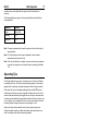
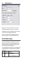
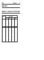
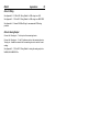
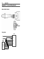
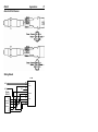
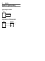
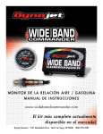
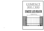
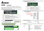
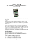
PLM User’s Manual MoTeC Contents Introduction ...................................................................... 3 Meter Operation ................................................................ 4 PLM Connections ..........................................................................................................4 Connectors .............................................................................. 4 Analog Output.......................................................................... 4 Digital inputs............................................................................ 5 Communications ...................................................................... 6 PLM Display....................................................................................................................6 Sensor Placement.........................................................................................................7 Sensor Warm-up ...........................................................................................................9 Sensor Lifetime..............................................................................................................9 Lambda .........................................................................................................................10 Engine Tuning ..............................................................................................................10 Operating Tips..............................................................................................................11 PLM Setup Software.........................................................12 Computer requirements .............................................................................................12 Connecting to a PLM...................................................................................................12 Installing PLM Setup ...................................................................................................12 Configurations..............................................................................................................12 Managing Configurations ......................................................... 13 Changing Configurations ......................................................... 14 Sensor Calibration ...........................................................19 Introduction ...................................................................................................................19 Calibration Methods ....................................................................................................19 Use Measured Calibration Value.............................................. 19 Enter Calibration Value ........................................................... 19 Calculate from O2 Concentration (Free Air)............................... 20 Enter Calibration Table............................................................ 21 PLM Communications.......................................................22 CAN Messages ............................................................................................................22 Configuring Basic CAN with an ADL......................................... 23 Configuring basic CAN with an M800........................................ 23 CAN Collect Functionality...........................................................................................24 Configuring the CAN collect master unit (PLM 1)....................... 24 Configuring the CAN Collect slave units (PLM 2 to PLM 16)........................................................................................ 25 MoTeC PLM User’s Manual CAN Unit Number Display .........................................................................................26 RS232 Messages ........................................................................................................27 Specifications...................................................................28 Meter .................................................................................... 28 Appendices ......................................................................31 Appendix A – Lambda to Air Fuel Ratio Table........................................................31 Appendix B – PLM Display Codes ............................................................................32 Appendix C – PLM CAN Diagnostic Codes ............................................................33 Appendix D – PLM Connector Details......................................................................34 Appendix E – Sensor Wiring Details ........................................................................36 Bosch LSU 4 Sensor.............................................................. 36 NTK – UEGO Sensor.............................................................. 38 Appendix F – PLM to ECU Wiring Details................................................................40 Analog Output........................................................................ 40 CAN...................................................................................... 40 Appendix G – PLM to ADL Wiring Details ................................................................41 Appendix H – General CAN Bus Wiring...................................................................42 Appendix I – PC Comms Wiring ...............................................................................43 Appendix J – Analog Output Wiring ..........................................................................44 Appendix K – Digital Input Wiring..............................................................................46 Typical wiring for switches....................................................... 46 Typical wiring for RPM measurement ....................................... 46 Appendix L – Glossary................................................................................................47 Appendix M – CAN Messages Format.....................................................................48 Appendix N – RS232 Message Format...................................................................53 Appendix O – Recommended CAN Collect Configuration ..................................54 Appendix P – Dimensions .........................................................................................57 Copyright – Motec Pty Ltd – 2001-2005 The information in this document is subject to change without notice. While every effort is taken to ensure correctness, no responsibility will be taken for the consequences of any inaccuracies or omissions in this manual. 23 June, 2005 MoTeC PLM Setup Software Introduction The MoTeC Professional Lambda Meter measures Lambda (or Air Fuel Ratio) over a wide range of mixtures with fast response time. The display may be set to Show Lambda, Air Fuel Ratio (for Petrol, Alcohol, Gas, Diesel or ‘blend’ fuel), equivalence ratio or percentage oxygen. The PLM provides a differential Analog Output Voltage proportional to Lambda that may be connected to an Analog Meter or other measurement instrument such as an ECU, Data Logger or dynamometer. The PLM also supports RS232 and CAN data links to devices such as the Motec Dash Logger or M800 ECU for transmission of sensor and diagnostic data. This manual covers the configuration and operation of the meter. 3 4 Meter Operation Meter Operation PLM Connections Connectors The PLM has a male and a female D-9 pin connector. See Appendix D – PLM Connector Details for a description of the PLM pinout. Male Connector The loom supplied with the PLM is fitted to the male PLM connector, for connection to the sensor and to a power supply. The Power supply must provide enough current (up to 5 Amps at start up) for both the meter and the sensor heater element. The vehicle battery is typically the most convenient source of power. It is not recommended that the power and sensor loom be extended by using a standard serial cable. These are unable to supply the current required by the sensor heater. If an extension is made, the wire must be at least 20 gauge. Female Connector The female PLM connector has pins for serial connection to a PC, CAN data bus, 2 digital inputs and the analog voltage output. The pinout is assigned to allow direct connection to a PC with a standard (straight through) 9 pin serial cable. Note that the PC must have a serial communications port (normally marked COM1). A custom cable is required to use the other features on this connector. Analog Output The analog output provides a voltage proportional to Lambda. The scaling of the analog output can be changed by using the PLM Setup software to configure the device (see Setup | Analog Output in the PLM Setup Software section). MoTeC Meter Operation 5 The analog output is provided as a differential voltage using two connector pins (Analog Out+ and Analog Out-). For correct operation Analog Out- must be connected to the ground reference on the monitoring system. The analog output can be configured as a wide band sensor input into a MoTeC ECU for tuning, as described below. See Appendix F – PLM to ECU Wiring Details for wiring details. M4/M48 ECU PLM Configuration Output Function = ‘LA V1’ table La = 0.000, Aout = 0.000V La = 5.000, Aout = 5.000V ECU Configuration Lambda Sensor Calibration = 1 (‘Narrow Band or MoTeC AF Meter’) M8/M800 PLM Configuration Output Function = ‘LA V1’ table La = 0.500, Aout = 0.000V La = 1.750, Aout = 5.000V ECU Configuration Lambda Sensor Calibration = 39 (‘MoTeC Meter’ or ‘MoTeC AFM1 Meter’) Digital inputs Digital Input 1 can be enabled as a switch input or RPM input. If the input is enabled, the PLM can be configured to operate based on the switch state (active high or active low) or on a non-zero RPM reading. The RPM reading is also transmitted in the CAN and RS232 data streams. Digital Input 2 can be enabled as a switch input, and the PLM can be configured to operate based on the switch state (active high or active low). This input can also be configured to change the display units on the PLM display. For more information, see Setup | Digital Inputs in the PLM Setup Software section. The digital inputs have a 4.7kohm pull-up resistor, and a switching threshold of around 2.5volts. 6 Meter Operation Communications RS232 Interface The RS232 interface is used for configuring the PLM from a PC, and for transmitting data to third party equipment. For configuration from a PC, the PLM can be directly connected using a standard (straight through) 9 pin serial cable. See Appendix I – PC Comms Wiring for details on wiring to a PC. CAN Interface The CAN interface is used for transmitting data to MoTeC devices such as the ADL (Advanced Dash Logger) or M800 ECU, or to third party equipment that supports CAN. The CAN communications can be configured to allow one PLM unit to collect CAN data from up to 15 other PLM units, and then retransmit the data on a single CAN address and on the RS232 interface. For detailed information on communications interfaces, see the PLM Communications section. PLM Display Start-up Display On powerup, the PLM displays the current firmware version (eg. 1.1.0) for one second, followed by a unit number based on the current CAN communications configuration. This unit number, displayed for one second, is useful for troubleshooting networks of multiple PLM units. See the PLM Communications section for more detail on displayed unit numbers. Status Display Whenever the sensor is not in control or is warming up, a series of displayed codes describes the current status. A description of these codes is given in Appendix B – PLM Display Codes. MoTeC Meter Operation 7 If the PLM loses control of the sensor at any point, then the sensor warm-up process is repeated and these codes are displayed again. Sensor Readings The displayed format of sensor readings can be configured to select the display units, decimal places, update rates and filtering. For more information, see Setup | Display in the PLM Setup Software section. If the reading is too large to be displayed using the configured settings, the display will only show ‘- -‘. Backlighting The backlight intensity is configurable from 0% to 100%. Sensor Placement The sensor should be fitted to the exhaust system with the sensor tip protruding into the exhaust gas flow. The sensor placement should be on an angle of between 10 and 90 degrees to the vertical, with the tip of the sensor pointing down. This is to ensure that no condensed water builds up between the sensor case and the sensor ceramic. It should not be placed vertically due to excess heat soak in this position. It is recommended that where possible the sensor be placed at least 1m from the exhaust ports to avoid excessive heat and at least 1m from the open end of the exhaust system to avoid incorrect readings due to outside oxygen. This is however not mandatory, and where necessary for shorter exhaust systems the sensor should be placed closer to the engine. The placement of the sensor should be away from the flame front coming out of the cylinder head and away from areas where one cylinder may have more affect than another. 8 Meter Operation Correct sensor placement Incorrect sensor placement MoTeC Meter Operation 9 Exhaust slip joints should be avoided near sensor placement as some designs allow air to enter. Slip joints can be reversed to make them better for use near sensors. Introduced air No air introduced Exhaust flow Exhaust slip joint design to avoid incorrect lambda readings Sensor Warm-up The internal heater in the LSU or NTK sensor is powerful enough to allow accurate measurement when gas temperature is at room temperature. The Bosch LSU will take ~20seconds to heat up, while the NTK ~30 seconds before reading. The maximum continuous operating temperature of the sensors is 850 degrees, and sensors should not be used for a prolonged period at temperatures higher than this. The sensor can be heated to 930 degrees for a short period (not exceeding 10 minutes), but the accuracy may be reduced. Sensor Lifetime The sensor life time is dependant on the type of fuel being used and the volume of gas flow over the sensor. The sensor can also be contaminated by exhaust manifold sealants, so Exhaust Gas Sensor friendly sealants should be used. Leaded fuel will reduce the sensor lifetime substantially due to lead contamination of the sensor element. Typically, for high performance engines the sensor should last at least 500 Hrs in unleaded fuel and 50 Hrs in leaded fuel. Longer lifetimes can be expected for less demanding applications. 10 Meter Operation At the end of its life the sensor becomes slow to respond and does not read rich properly. The NTK and LSU are designed to be accurate for 50,000km of operation in a road car, so the above figures are a conservative estimate. Sensor lifetime will be reduced by contaminants such as lead, silicon, oil, etc. Thermal cycling will also age the sensor more rapidly, along with exposure to exhaust fumes without any heating control active (ie: not connected to the PLM). Regular performance of the Free Air Calibration will maintain the accuracy of the sensor over its lifetime. Sensor Temperature It is important to ensure that the sensor is not overheated due to incorrect placement in the exhaust as this significantly reduces the sensor life. The sensor impedance (Zp) is measured by the PLM, and this is a reasonable indication of sensor temperature. Zp should be approximately 80 Ohms in normal operation. If Zp is less than 60 the sensor is being overheated by the exhaust and the sensor life will be reduced. Lambda Lambda gives a measure of Air Fuel Ratio that is independent of the type of fuel being used. Lambda 1.0 corresponds to the stoichiometric ratio i.e. when there is no excess fuel and no excess air. Lambda > 1.0 => Excess Air (Lean) Lambda < 1.0 => Excess Fuel (Rich) Lambda may be directly converted to Air Fuel Ratio for a specific fuel using a multiplication factor. The PLM will display Air Fuel Ratio by loading the appropriate configuration into one of the output tables. For more information, see Setup | Display in the PLM Setup Software section. A table to convert Lambda to Air Fuel Ratio for various fuels is given in Appendix A – Lambda to Air Fuel Ratio Table. Engine Tuning The desired Air Fuel Ratio (or Lambda) is dependant on the tuning objective i.e. Power, Economy or Emissions. Normally at full load the engine is tuned for MoTeC Meter Operation 11 maximum power and at light loads the engine is tuned for emissions or economy. The following table gives a guide to the required Lambda values for different tuning objectives. Objective Lambda Power 0.84 to 0.90 Economy 1.05 Emissions 1.00 Note: The exact requirements for a specific engine and fuel must be found by experimentation. Note: On Turbo Engines extra fuel may be desirable to reduce exhaust temperatures and help avoid knock. Note If the vehicle is fitted with a catalytic converter extra fuel may be required to ensure the catalyst does not overheat when not operating at Lambda 1.00 Operating Tips If the Engine misfires for any reason, including an over-rich mixture, the Meter may falsely read Lean. This is due to excess air being present in the exhaust gasses which is caused by incomplete combustion when the engine misfires. Other areas that can give misleading readings include at high RPM, closed throttle when the mixture won’t burn completely. Following overrun fuel cut the sensor will become saturated with oxygen and can take up to several seconds to resume accurate readings. Engine misfires include hitting the rev-limiter, be it a fuel or ignition cut or a combination of both, and can give a similar result with time being required to purge the sensor of excess oxygen or fuel. Engines with high overlap camshafts running at low speed may pump air through the engine resulting in a false lean reading, therefore the meter may need to read leaner than would otherwise be expected. 12 PLM Setup Software PLM Setup Software The PLM Setup Software allows a PLM unit to be configured from a PC for a particular target application. A new PLM unit must be configured before its initial use in order to specify sensor type, display units etc. This section covers the basic configuration of the PLM. Advanced functions are also covered in the PLM Communications and Sensor Calibration sections. Computer requirements The PLM setup software runs under Windows 95, 98, ME, NT4, 2000 or XP operating systems. The minimum recommended PC specification is a Pentium 90 with 16MB RAM and a serial port. Connecting to a PLM The PLM connects to the PC with a standard (straight-through) serial communication cable from the PC serial port to the 9pin Female PLM connector. During PC operations (sending or retrieving), the PLM should be powered using the sensor loom. Installing PLM Setup The PLM Setup software can be installed either from the MoTeC Resource CD supplied with the PLM, or from the MoTeC website (software.motec.com.au) To start the program after installation, click on Start à Programs à MoTeC à PLM Setup à PLM Setup Configurations The PLM configuration determines exactly how a unit will operates. The PLM Setup software allows changes to be made to a configuration to change PLM characteristics such as the sensor type, display units, analog output scaling, backlight intensity etc. MoTeC PLM Setup Software 13 Standard configuration templates for most common preferences are included with the software. Managing Configurations When the PLM Setup software is started, a configuration file needs to loaded before changes can be made, or before a configuration can be sent to the PLM. This configuration can either be loaded from a file on disk, retrieved from the PLM (using the serial cable), or created as a new configuration. A loaded configuration can be saved to a file on disk, and then sent to the PLM (using the serial cable). A modified configuration must be sent to the PLM for it to take effect. Creating a new configuration To create a new configuration, select File | New from the main menu, and choose a template to base the new configuration on. Loading an existing configuration from disk To open an existing configuration file, select File | Open from the main menu and select the desired file. The most recently used files may be opened from the list of files at the bottom of the File menu. Retrieving an existing configuration from a PLM To retrieve a configuration from a PLM, select Online | Get Configuration from the main menu. To specify the serial port used for the connection to the PLM, select Options | Communications Port from the main menu. The PC must be connected to the powered PLM using the serial port specified. It is advisable to retrieve the initial configuration from the PLM and save this before making modifications. Saving a configuration to disk After a configuration has been created or modified it should be saved with a meaningful name by selecting File | Save or File | Save As from the main menu. Sending a configuration to a PLM To send a configuration to a PLM, select Online | Send Configuration from the main menu. To specify the serial port used for the connection to the PLM, 14 PLM Setup Software select Options | Communications Port from the main menu. The PC must be connected to the powered PLM using the serial port specified. When a configuration file is sent to the PLM, any changes are automatically saved to the current configuration file on the PC. Changing Configurations Once an existing configuration file has been opened or retrieved, or a new configuration has been created, the configuration may be modified by choosing the options under the Setup menu. Setup | Sensor Sensor: The sensor type used with the PLM (NTK, Bosch LSU 4 or Bosch LSU 4.2) must be specified before a configuration can be sent to a PLM. It is important to select the correct sensor type to prevent damage to the sensor and ensure correct lambda measurements. Calibration: There are several options available for choosing the calibration method of the sensor being used. The default option, ‘Use measured calibration value’ allows the PLM to determine the factory sensor calibration and can be used in most cases. If the calibration value of the sensor is known then it can be entered by selecting the option ‘Enter calibration value’. This value is engraved on sensors supplied by MoTeC as an equivalent resistor calibration value. Either of these two options will be sufficient in nearly all situations. The more advanced calibration methods (‘Calculate from O2 concentration’ and ‘Enter calibration table’) are described in the section Sensor Calibration. Heater Control: This parameter allows the heater voltage to be set when using an NTK sensor. For most situations this can be left at the default value of 10.5 volts. A value of 12 – 12.5 volts will give better results during cold start or warm-up calibrations or during extensive periods of overrun fuel cut where the sensor may become too cold for accurate measurement. Running the MoTeC PLM Setup Software 15 heater at a sustained voltage above 10.5 volts will reduce the sensor lifetime. Sensor Timeout: The option to ignore sensor errors is only recommended for very specialised applications where extreme changes in lambda may cause a short loss of sensor control. Enabling this option will disable the default PLM behaviour of shutting down the sensor for a timeout period when control is lost. This timeout is to protect the sensor as loss of control can indicate a wiring fault. Setup | Display Output Tables: The Output Table Setup dialog is displayed when the Output Tables button is clicked. The Output Tables are used by the PLM to calculate the displayed value. The PLM stores two tables that can be configured with different calibrations for displaying lambda, air fuel ratio or equivalence ratio. In addition to a lambda calibration, there are a number of pre-defined calibrations for air fuel ratio for different fuels. To display one of these, the calibration must be loaded by clicking on the ‘Load’ button and choosing the appropriate calibration from the list displayed. Advanced users can generate their own calibration tables using the Ipn (normalised sensor pump cell current) value measured by the meter. These user calibrations can be saved for re-use by clicking the ‘Save As’ button. Output to Display: The default PLM display value can be selected as the result from one of the two tables that are specified under the Output Tables setup. Display Decimals Table 1 / Table 2: This is the number of decimals used to display the values from Table 1 and Table 2 in the Output Tables setup. The display decimals are specified for both tables as the PLM can be configured to swap the display between the two tables using a digital input. Normal use would be to 2 decimal places for lambda. 16 PLM Setup Software Display Update Rate: The update rate of the displayed value can be from 1 to 10 times per second. Filter Time: The display data can be filtered so that it is more stable and easier to read. This filtering is independent of the update rate. The filter time can be specified in 0.1second units from 0 to 25 seconds. Backlight Intensity: Backlight intensity is configurable from 0 to 100% Setup | Digital Inputs Device Activation: If digital inputs are not used for PLM activation, the ‘Run always’ option should be selected. The remaining four options allow the PLM to be activated either while a digital input (1 or 2) remains active, or after a digital input (1 or 2) first becomes active. If one of digital input device activation modes is selected, the corresponding digital input mode must be configured as Active Low, Active High or Measure RPM. This allows the PLM to be configured to operate only when measuring RPM, or when a switch is set. Input 1 Mode: ‘Off’ – digital input 1 is disabled ‘Active High’ – digital input 1 is active when the input voltage is high ‘Active Low’ – digital input 1 is active when the input voltage is low ‘Measure RPM’ – digital input 1 is active when a non-zero RPM is measured and the RPM value is transmitted in the CAN and RS232 data streams (if configured under the communications setup). RPM Pulses per Revolution: If Input 1 Mode is ‘Measure RPM’ the number of pulses per engine revolution must be specified here to calibrate the RPM measurement. MoTeC PLM Setup Software 17 Input 2 Mode: ‘Off’ – digital input 2 is disabled ‘Active High’ – digital input 2 is active when the input voltage is high ‘Active Low’ – digital input 2 is active when the input voltage is low ‘Display Other Output Table When Low’ – the other output table is used for the display value while digital input 2 is low. For example, if Output to Display (in the Setup | Display menu) is table 2, then table 1 will be displayed while digital input 2 is low. Setup | CAN Messages The configuration templates included with PLM Setup are all configured to send CAN data to a MoTeC ADL (Advanced Dash Logger) or M800 ECU by default. The Output to Transmit parameter specifies the output table to be used for transmitted values. The Output Table Setup dialog is displayed when the Output Tables button is clicked. Note that the two tables setup in this dialog are used for displayed values, transmitted values and analog outputs, but each function can use either table 1 or table 2. For use with MoTeC equipment (ADL or M800), the selected table must be setup for Lambda with 3 decimal places. Other table setups should only be used for interfacing with third party equipment. For basic CAN communications with an ADL, the Address parameter for Message 1 should match the address in the PLM CAN communications template loaded in the ADL. If multiple PLMs (up to six units) are connected to an ADL then each should be given a different address. The addresses chosen must match those of the PLM CAN communication templates provided with Dash Manager. For example, the ADL template ‘PLM #1 (CAN ID 460)’ requires that the Message 1 Address be 460. Note that “CAN Collect” functionality is the preferred method for communications from more than one PLM to an ADL. For basic CAN communications with an M800 ECU, the Address parameter for Message 1 should be 460 for the first PLM, 461 for second PLM etc. Only advanced users should change the other CAN message settings, or configure Collect Master functionality. CAN Messages are covered in more detail in the PLM Communications section. 18 PLM Setup Software Setup | Analog Output Output Table: The Output Table Setup dialog is displayed when the Output Tables button is clicked. Note that the two tables setup in this dialog are the same tables used for displayed values, transmitted values and analog outputs, but each function can use either table 1 or table 2. Output Function: This parameter specifies input to the analog output Calibration Table. The ‘Ip’ and ‘Ipn’ options are the raw and normalized sensor pump cell currents (Ipn is normalized using the calibration method specified under Setup | Sensor). The other options are the two tables that are specified under the Output Tables setup. Calibration Table: The calibration table allows users to set the voltage output that corresponds to the table input value. The table takes the input value and translates it to an analog voltage (0 to 5 volts) by way of the calibration table. The voltage is linearly interpolated between points in the table, so at least two pairs of values must be entered in the table. Once created, calibration tables can be saved (using the Save As button), and reloaded (using the Load button) for use in other configurations. Default Output: The analog output voltage is set to the Default Output voltage if the PLM is not active or if the analog output is disabled. MoTeC Sensor Calibration 19 Sensor Calibration Introduction The NTK and Bosch lambda sensors are factory calibrated with a trimming resistor embedded in the sensor connector. This resistor value can be read by the PLM and used to calibrate the sensor readings for a new sensor. As sensors age their calibration changes. To maintain accurate readings, the PLM allows comparison of the measured O2 concentration in air against that of the pure O2 reference in the sensor itself to calculate a new calibration. Sensor calibration values in the PLM Setup software are expressed as either an equivalent calibration resistor value, or as a gain factor. It is recommended that all applications that require sensor calibration values to be measured and recorded (such as workshops using multiple sensors) should use the gain factor calibration number rather than the equivalent resistor. Support for equivalent resistor calibration values is included for backwards compatibility with previous PLM software. Calibration Methods There are four calibration methods available under the Setup | Sensor menu. Use Measured Calibration Value The factory calibration resistor is measured by the PLM and used to calibrating readings. The factory sensor plug must be present to use this calibration method. Enter Calibration Value A previously measured calibration value can be entered directly as either an equivalent calibration resistor value or as a gain factor value. Entered calibration values are useful when sensors are calibrated using the free air calibration (O2 concentration). The results of the free air calibration can be recorded for a particular sensor and then entered when the sensor is used with another PLM. 20 Sensor Calibration Calculate from O2 Concentration (Free Air) This calibration method uses the known oxygen concentration of free air to calibrate a sensor. Re-calibration using this method allows a sensor to maintain accuracy as it ages. To perform the free air calibration, the PLM must be powered up and connected to a PC (with a serial cable) running the PLM Setup software. The configuration in the PLM must match the sensor type being used for the calibration. Free air calibration must be done in the open air – not in a workshop or dyno room where there will be large amounts of hydrocarbons in the atmosphere. The O2 Concentration parameter specifies the actual % concentration of Oxygen in the atmosphere and should be entered if known. A nominal value of 20.94% is given, but the more accurately this is known for current atmospheric conditions (temperature, pressure) the more accurate the calibration will be. To start the calibration process, click the ‘Calibrate’ button. The following dialog is displayed while the sensor readings stabilize. When the sensor reading is stable the calibration can be stored by clicking the Store button, as shown below. The new calibration value is displayed as both a gain factor and an equivalent resistor calibration. This calibration can be recorded against the sensor serial number to allow the sensor to be used with another PLM unit by simply entering the calibration value. MoTeC Sensor Calibration 21 To apply the new calibration, the PLM configuration must be saved and sent to the PLM. Enter Calibration Table For advanced applications, a calibration table can be specified to calculate Ipn (normalized sensor pump cell current) from Ip (sensor pump cell current). At least two pairs of values must be specified in the table, and linear interpolation is used between the points. Calibration tables may be saved and reloaded for use in other calibrations. 22 PLM Communications PLM Communications CAN Messages The PLM can transmit up to four CAN messages containing readings and diagnostics. The format of these four messages is fixed (see Appendix M – CAN Messages Format), but the following parameters can be configured by the user for each message under the Setup | CAN Messages menu. Address Format: Standard address formatting is recommended for most applications. Extended addressing should normally only be used if required for interfacing to third party equipment, however it is supported by the ADL if required. Address: The CAN address for a message is specified in hex. The recommended address range for PLM messages is hex 460 to hex 46F. Compound ID: The compound ID (0 to 255) is placed in the first data byte of the CAN message and is used to differentiate between messages sent to a single CAN address. Multiple messages can be transmitted to a single address by specifying different compound IDs for each message. Message Rate: The message rate (1,2,5,10,20 or 50 times per second) determines how often the CAN message is transmitted. Scaling The scaling of the actual reading for the PLM is determined by the Output to Transmit parameter which specifies the output table to be used for transmitted values (eg. Lambda, O2 concentration etc.). MoTeC PLM Communications 23 For use with MoTeC equipment (ADL or M800), the selected table must be setup for Lambda with 3 decimal places. Other table setups should only be used for interfacing with third party equipment. Configuring Basic CAN with an ADL To connect a small number of PLM units (maximum of six) to an ADL, the ADL must use one CAN template (PLM#1 to PLM#6) for each PLM. The PLM units must be configured as follows to match the ADL templates. Output To Transmit LA V1, with 3 decimal places in the table Address Format Standard Address As per ADL template (460 to 465) Compound Id Message 1 = 0 Message 2 = 1 Message 3 = 2 Message 4 = 3 Message Rate Message 1 = User defined Message 2 = User defined Message 3 = User defined Message 4 = User defined Collect Master = Off Configuring basic CAN with an M800 Up to 12 PLM units can transmit to an M800 ECU if configured as follows: Output To Transmit LA V1, with 3 decimal places in the table Address Format Standard Address PLM 1 = 460 PLM 2 = 461 …. PLM 12 = 46F 24 PLM Communications Compound Id Message 1 = 0 Message Rate Message 1 = User defined Message 2 = Off Message 3 = Off Message 4 = Off Collect Master = Off CAN Collect Functionality For applications involving multiple PLM units, a single PLM can be configured to collect calibrated lambda readings from up to 15 other PLMs on the CAN bus, and to retransmit the 16 readings on a single CAN address. This functionality is available in PLM firmware V1.1 and later. Note that only the calibrated lambda reading is collected and re-transmitted. If the CAN collect feature is used, PLM Diagnostic CAN messages may still be turned on, but care must be taken in assigning addresses not to interfere with messages from the other PLMs. Configuring the CAN collect master unit (PLM 1) Only one PLM on the CAN bus should be configured as a Collect Master. To enable the CAN collect functionality, a base address and a message rate must be specified in the Collect Master tab of the CAN Message Setup dialog. MoTeC PLM Communications 25 The base address is the address on which the collected Lambda values will be retransmitted. This address must lie on a 16 message boundary (i.e. the address, in hex, must end in 0). The base address also defined the addresses of the Collect slave units that the master will monitor. The recommended address is Hex 460. The message rate is the rate at which the Lambda values are retransmitted on the CAN bus to the measuring device (usually an ADL or ECU). Messages 1 to 4 do not need to be configured on the master unit. Output to Transmit must be LA V1, with 3 decimal places in the table setup. The master PLM unit will briefly display “CU 1” (Collect Unit 1) on start-up after displaying the firmware version. If the slave PLM stops transmitting to the master PLM for 1.5 seconds then the master PLM will retransmit a value of 0 for the missing slave. Configuring the CAN Collect slave units (PLM 2 to PLM 16) The Message 1 tab of the CAN Message Setup dialog must be configured as follows: Output To Transmit LA V1, with 3 decimal places in the table Address Format Standard Compound ID 00 Message Rate As required for application. This is the rate at which the Lambda value for this unit will be sent to the master unit. Address Master PLM Collect Master Base Address + PLM number – 1 (in hexadecimal) Eg. For a master PLM base address Hex 460: PLM 5 address would be Hex 464 PLM 12 address would be Hex 46B 26 PLM Communications Messages 2 to 4 are not required and should be “OFF” on the slave units. The Collect Master message rate must be set to OFF on the slave units. A PLM configured as a slave unit will briefly display the PLM unit number (eg “U 4” for PLM 4) on start-up after displaying the firmware version. Appendix O – Recommended CAN Collect Configuration describes the recommended configuration for connecting multiple PLM units to an ADL. CAN Unit Number Display On power-up, a PLM will display a unit number based on the current CAN communications configuration. This unit number is displayed for one second after the firmware version has been displayed. The unit number is useful for trouble shooting systems containing multiple PLMs. The unit number displayed is based on whether the unit is a Collect Master, and on the least significant digit of the CAN address specified for CAN Message 1, as shown below. Display PLM Number Configuration U0 PLM 0 Collect Master disabled Message 1 disabled (Message Rate = Off) MoTeC PLM Communications CU1 PLM 1 Collect Master enabled U1 PLM 1 Collect Master disabled 27 Message 1 address = xx0 U2 PLM 2 Collect Master disabled Message 1 address = xx1 … … … U16 PLM 16 Collect Master disabled Message 1 address = xxF A correctly configured network of PLMs using the CAN collect functionality should have the unit numbers CU1, U2, U3, U4 etc. A correctly configured network of PLMs that are not using the CAN collect functionality should have the unit numbers U1, U2, U3, U4 etc. A correctly configured PLM that is not using CAN communication should have the unit number U0. RS232 Messages The PLM transmits RS232 status messages at a rate of 20 times a second. If the PLM is configured as a CAN Collect Master then the transmitted message contains the Lambda values for the master PLM and up to 15 slave PLMs. If the PLM is not configured as a CAN Collect Master the transmitted message contains Lambda values and diagnostics for the PLM. Appendix N – RS232 Message Format describes the format of the RS232 Messages. Note that the number of decimal places for calibrated sensor readings depends on the selected output table in the PLM configuration. The transmitted messages conform to the MoTeC generic data protocol and are sent at 9600 baud, 8 data bit, no parity, 1 stop bit (9600, 8N1). 28 Specifications Specifications Meter Power Supply Input Voltage Range 7 to 16Volts Input current 60mA typical, backlight off 110mA typical, backlight on Plus sensor heater current Protection Reverse polarity protected Load Dump Clamp Max 40V at 100 Amp 100msec Sensors Sensors 1 Compatible Types Bosch LSU 4/ Bosch LSU 4.2/ NTK UEGO Calibration Methods Automatic using sensor’s built in calibration resistor Manual Table Entry Known Oxygen Environment Calibration Constant Type Detection Manual Sensor Thread M18 x 1.5 Max Exhaust Temp 850 deg Normal Temp Range 150 – 800 deg Measurements Lambda 0.7 to 32.0 02 0 to 22% A/F Ratio Fuel dependant (see lambda range) Accuracy +/- 1.5% (sensor specific) MoTeC Specifications 29 Sensor Heater Outputs 1 Current Max 8 Amp Control Bosch - Digital PID NTK - Constant Voltage Voltage supply to the PLM should be at least 11V for proper operation of the sensor heater when using an NTK UEGO sensor. Output Output Type Differential Calibration User Programmable Max Output Current 10mA (Short circuit protected) Output Voltage Swing 0 to 4.5V relative to the negative output (when the negative output is less than 0V and greater than negative 4.5V (relative to Battery-) and for output currents less than 1mA. If the negative output is greater than 0V then the output voltage swing will be reduced by the voltage on the negative output (relative to Battery-) If the negative output is connected to a floating device such as a multimeter or other high impedance measuring device then it will float in the range 1.25V to 2.5V, this will reduce the output voltage swing by 2.5V to 0 to 2V. In this case connecting the negative output to Battery- will restore the full output voltage swing. Negative Pin Output Voltage Range Must be within -4.5 to +5 volts (relative to Battery-) The negative out put has an impedance of approximately 5kohm connected to a variable voltage in the range 1.25V to 2.5V (relative to Battery-) Min Positive Pin Output Voltage -4.5V (relative to Battery-) for current less than 1mA 30 Specifications Max Positive Pin Output Voltage 4.5V (relative to Battery-) for current less than 1mA Inputs Digital 2 x User Programmable as RPM or PLM Operate Communications CAN 1Mbit RS232 9600 baud, 8 data bits, no parity, 1 stop bit (9600, 8N1) Display Type LCD 3.5 Digit Digit Height 12.7mm Lighting Green LED Back Light Connection Connectors 2 x 9 Pin Dsub (commonly called D9) Environment Temperature Range -10 to 70 Deg C Case Dimensions(WxHxD) 105x41x25 mm (Excluding Connector) Weight 135grams MoTeC Appendices 31 Appendices Appendix A – Lambda to Air Fuel Ratio Table Lambda 0.70 0.75 0.80 0.85 0.90 0.95 1.00 1.05 1.10 1.15 1.20 1.25 1.30 1.35 1.40 1.45 1.50 1.55 1.60 Air Fuel Ratio Petrol 10.3 11.0 11.8 12.5 13.2 14.0 14.7 15.4 16.2 16.9 17.6 18.4 19.1 19.8 20.6 21.3 22.1 22.8 23.5 Alcohol 4.5 4.8 5.1 5.4 5.8 6.1 6.4 6.7 7.0 7.4 7.7 8.0 8.3 8.6 9.0 9.3 9.6 9.9 10.2 LPG 10.9 11.6 12.4 13.2 14.0 14.7 15.5 16.3 17.1 17.8 18.6 19.4 20.2 20.9 21.7 22.5 23.3 24.0 24.8 Diesel 10.2 10.9 11.6 12.3 13.1 13.8 14.5 15.2 16.0 16.7 17.4 18.1 18.9 19.6 20.3 21.0 21.8 22.5 23.2 32 Appendices Appendix B – PLM Display Codes Warm-up Codes C-6 Sensor Protection Shutdown. The C-6 state is entered when the PLM can not pump enough current into the pump cell to balance the sense cell. When C-6 is entered pump current is turned off. The PLM will try to gain control of the sensor (the C-1 state) every 10 seconds. If it is then unable to regain control after 2 seconds then it will re-enter the C-6 state. C-5 User Stop. The sensor has been turned off via a digital input C-4 No Heater detected. This will occur if the sensor is disconnected or the heater is open circuit – ie: the sensor is damaged. Heater circuit should be approx 3ohms at room temp C-3 Warm Up. The PLM is heating the sensor prior to normal operation and waiting for sensor to warm up. C-2 Control Initialization. Waiting to start pump current C-1 Checking Operation. Waiting to get control of sensor cell voltage. In normal operation the PLM will display C-3, C-2, C-1 then start reading lambda values. The C-4 and C-6 error states will occur if a problem is detected. Error Codes 0010 The config loaded into the PLM does not match the PLM firmware version 0011 The config stored in the PLM is corrupt (CRC failure) 0020 The factory calibration values does not match the PLM firmware version 0021 The calibration stored in the PLM is corrupt (CRC failure) MoTeC Appendices 33 Appendix C – PLM CAN Diagnostic Codes These are the bit field descriptions for the diagnostic error groups that are sent to the ADL via the CAN link. Diagnostic Group 1 1: No Sensor 2: Sensor Hot 4: Sensor Cold 8: Sensor Faulty 32: Warm Up 64: Ref voltage out of range Diagnostic Group 2 These codes correspond to those displayed by the PLM. 1 (C-1) - Checking Operation. 2 (C-2) - Control Initialization. 4 (C-3) - Warm Up. 8 (C-4) - No heater detected. 16 (C-5) - User Stop (sensor turned off via digital input). 32 (C-6) - Sensor Protection Shutdown. 34 Appendices Appendix D – PLM Connector Details Sensor Connector - Male D9 1 2 3 4 5 6 7 8 9 Battery +12 Power (Note 2) Heater + Rc Ip Sensor Common Battery 0V Power Heater – Vs Ipr Auxiliary Connector – Female D9 1 2 3 4 5 6 7 8 9 CAN Hi (Note 3) RS232 Tx RS232 Rx Digital Input 1 Comms 0V CAN Lo (Note 3) Digital Input 2 Analog out + (Note 4) Analog out – (Note 4) Note1: Extension of Standard Sensor Loom The length of the standard loom supplied for connection of the PLM to a sensor is 2.5m. Longer looms are available from MoTeC by request. It is not recommended that the loom is extended by using a standard serial cable. These are unable to supply the current required by the sensor. If an extension is made, the wire thickness must be at least 20 gauge. Note 2: Power Supply Current If using a power supply other than the vehicle battery, start-up current for the sensor is up to 5A, though operating current is much lower than this, 0.5 – 1 Amps, depending on exhaust gas temperature. MoTeC Appendices 35 Note 3: Wiring See Appendix G – PLM to ADL Wiring Details for CAN wiring to an ADL See Appendix F – PLM to ECU Wiring Details for CAN wiring to an M800 ECU See Appendix H – General CAN Bus Wiring for recommended CAN wiring practices Note 4: Analog Output Connect the “Analog out +” to the input on the measuring device. Connect the “Analog out –“ to the 0V reference point on the measuring device. “Analog out –“ must be connected for the measuring device to make a correct reading. See Appendix F – PLM to ECU Wiring Details for wiring the analog outputs to M4/M48, M8 & M800 ECUs 36 Appendices Appendix E – Sensor Wiring Details Bosch LSU 4 Sensor Wiring Details PLM BAT+ BAT- N/C Bosch LSU 4 Ip Heater + Heater Common Vs Ipr 6 5 4 3 2 1 M1 BAT+ M2 Heater + M3 Rc M4 Ip M5 Common M6 BATM7 Heater M8 Vs M9 Ipr MoTeC Appendices Bosch LSU 4.2 Sensor Wiring Details PLM BAT+ BAT- N/C Bosch LSU 4.2 Ipr Common Heater Heater + Ip Vs 6 5 4 3 2 1 M1 BAT+ M2 Heater + M3 Rc M4 Ip M5 Common M6 BATM7 Heater M8 Vs M9 Ipr 37 38 Appendices NTK – UEGO Sensor MoTeC Appendices Wiring Details PLM M1 M2 M3 M4 M5 BAT+ BAT- NTK UEGO Heater + Heater Rc Common 1 2 6 3 4 5 N/C 6 Vs 7 Ip 8 Common N/C BAT+ Heater + Rc Ip Common M6 BATM7 Heater M8 Vs M9 Ipr 39 40 Appendices Appendix F – PLM to ECU Wiring Details Analog Output PLM wiring using the Analog Output to M4/M48/M8/M800 ECUs: PLM A out A out - M4/M48 F8 Red 31 La+ F9 Black 32 La - (Previously La- was shown connected to ECU 0V, this is now optional) PLM A out A out - M8 F8 Red 24A La+ F9 Black 36A La - 10A 0V PLM A out + A out - M800/M880 F8 F9 Red Black B25, B12 / 60, 61 B16 / 27 La1S or La2S Sensor 0V CAN One or more PLMs may be connected to the M800 ECU via the CAN bus. Note that the ECU version must be V3.0 or higher. See Appendix H – General CAN Bus Wiring for details on correct wiring and termination for CAN devices. MoTeC Appendices Appendix G – PLM to ADL Wiring Details One or more PLMs may be connected to the MoTeC ADL via the CAN bus. See Appendix H – General CAN Bus Wiring for details on correct wiring and termination for CAN devices. 41 42 Appendices Appendix H – General CAN Bus Wiring The CAN bus should consist of a twisted pair trunk with 100R (0.25Watt) terminating resistors at each end of the trunk. The preferred cable for the trunk is 100R Data Cable but twisted 22# Tefzel is usually OK. The maximum length of the bus is 16m (50ft) including the MoTeC CAN Cable (PC to CAN Bus Communications Cable) CAN Devices (such as MoTeC PLM, ADL, etc) may be connected to the trunk with up to 500mm (20in) of twisted wire. The connector for the CAN Communications Cable may also be connected to the trunk with up to 500mm (20in) of twisted wire and should be within 500mm of one end of the trunk. If desired two CAN Cable connectors may be used so that the MoTeC CAN Cable may be connected to either side of the vehicle. Both connectors must be within 500mm of each end of the trunk. CAN Device CAN Device CAN-HI CAN-LO 500mm Max CAN-HI CAN-LO CAN-HI CAN-LO CAN-HI CAN-LO 0V 8V 100R 100R << CAN Bus >> 500mm Max 1 Minimum one twist per 50mm (2in) CAN Cable Connector 5 4 3 These wires must be Twisted CAN-HI CAN-LO 100R Terminating Resistors at each end of the CAN Bus 500mm Max CAN Device Short CAN Bus If the CAN Bus is less than 2m (7ft) long then a single termination resistor may be used. The resistor should be placed at the opposite end of the CAN Bus to the CAN Cable connector. MoTeC Appendices 43 Appendix I – PC Comms Wiring A PC may be connected to the PLM by connecting to the 9 pin female connector as shown below. This allows the PLM to be configured using the PLM Configuration software. It is also acceptable to use a standard 1:1 male to female communications cable which connects all 9 pins. Note that during configuration the PLM must also have power connected to it via the PLM 9 pin male connector. PLM PC Serial Port 0V F5 RS232 Rx F3 RS232 Tx F2 5 Comms 0V 3 RS232 Tx 2 RS232 Rx Standard Serial Comms cable. This will connect all 9 pins, but only 3 wires are required. 44 Appendices Appendix J – Analog Output Wiring Floating Measuring Device When connected to a floating measuring device such as a multimeter, Aout– should be connected to Battery– as shown to ensure that the full output voltage swing is available. (See the specifications for details) Floating Measuring Device PLM A out + A out Battery- F8 Input + F9 Input – (0V) M6 Battery- Single Ended Input Measuring Device A single ended measuring device has the negative input internally connected to the devices ground pin. Note: The Ground voltage must not be more than 4.5 volts below Battery–. Note: If the Ground voltage is greater than the Battery – voltage then the PLM output voltage swing will be reduced. (See the specifications for details) Single Ended Measuring Device PLM A out + A out Battery- F8 Input + F9 Input - M6 Ground Battery- Ground Differential Input Measuring Device When connected to a differential input measuring device, Aout– should be connected to Battery– as shown to ensure that the full output voltage swing is available. (See the specifications for details) MoTeC Appendices 45 Note: Aout+ and Aout– must be within the within the input common mode range of the measuring device. This limits the voltage difference that can be between Battery– and Ground. Differential Input Measuring Device PLM A out + A out Battery- F8 Input + F9 Input – M6 Battery- Ground Ground 46 Appendices Appendix K – Digital Input Wiring Typical wiring for switches PLM Digital Input 1/2 0V Typical wiring for RPM measurement PLM RPM Sensor: Must be Hall Effect type Digital Input 1 0V Signal Sensor 0V 8V sensor supply MoTeC Appendices Appendix L – Glossary CAN – Controller Area Network. High speed serial data bus common in automotive applications Ip – Sensor pump cell current Ipn – Normalised Ip Vs – Sense voltage 47 48 Appendices Appendix M – CAN Messages Format Messages 1 to 4 can be optionally transmitted from any PLM unit. Messages 5 to 10 are only transmitted from a PLM unit configured as a CAN Collect Master. Message 1 Byte 0 3 4 5 6 Name Compound ID – user defined, default 0 Calibrated Sensor Output Value – user defined, default Lambda Heater duty cycle Device Internal Temperature Zp (Pump cell impedance) Diagnostic Field 1 7 Sensor state 1:2 Scaling N/A Hi:lo*1 = x.xxxLa (Note 1) Byte*1 = xxx% Byte*195/10-500 = xxx.xC Byte*1 = X ohm Sensor RUN 2 Sensor COLD 4 Sensor FAULT 8 Sensor WARM UP 32 ADC Ref fault 64 RUN 0 CONTROL_WAIT 1 PUMP_WAIT 2 WARM_UP 3 NO_HEATER 4 STOP 5 PUMP_OFF 6 MoTeC Appendices 49 Message 2 Byte 0 3 4 Name Compound ID – user defined, default 1 Ipn (Normalised pump cell current) Vs (Sense voltage) Vp (Pump cell voltage) 5 6:7 Reserved Ip (Raw pump cell current) 1:2 Scaling N/A Hi:Lo * 1 = X µA Byte*5 = X mV Byte * 10000 / 255 – 5000 = X mV N/A Hi:Lo * 1 = X µA Message 3 Byte 0 1 3 4 5 6 7 Name Compound ID – user defined, default 2 Bosch calibration resistor NTK calibration resistor Reserved Reserved Battery Voltage Sensor in control Scaling N/A Byte*1 = X ohm Byte*1 = x.x kohm N/A N/A Byte*1 = x.xV Sensor voltage within limits Sensor voltage outside limits 1 0 50 Appendices Message 4 Byte 0 3 Name Compound ID – user defined, default 3 Positive Analog output pin voltage Negative Analog output pin voltage Sensor type 4 Reset source (Note 2) 5 6:7 Firmware Version RPM HI:LO 1 2 Scaling N/A Byte*1000/255–500 = x.xx V Byte*1000/255–500 = x.xx V NONE NTK BOSCH LSU4 BOSHC LSU4.2 Low Voltage reset Illegal Address reset Illegal operation reset Watchdog timer reset External reset x.xx xxxxx RPM 0 1 2 3 2 8 16 32 64 Message 5 Byte 0 1 2:3 4:5 Name Compound ID = 4 Reserved PLM 1 (Master PLM) Calibrated Sensor Output Value PLM 2 Calibrated Sensor Output Value 6:7 PLM 3 Calibrated Sensor Output Value Scaling N/A N/A Hi:Lo*1 = x.xxxLa (Note 1) Hi:Lo*1 = x.xxxLa (Note 1) Hi:Lo*1 = x.xxxLa (Note 1) Message 6 Byte 0 1 2:3 Name Compound ID = 5 Reserved PLM 4 Calibrated Sensor Output Value 4:5 PLM 5 Calibrated Sensor Output Value 6:7 PLM 6 Calibrated Sensor Output Value Scaling N/A N/A Hi:Lo*1 = x.xxxLa (Note 1) Hi:Lo*1 = x.xxxLa (Note 1) Hi:Lo*1 = x.xxxLa (Note 1) MoTeC Appendices 51 Message 7 Byte 0 1 2:3 Name Compound ID = 6 Reserved PLM 7 Calibrated Sensor Output Value 4:5 PLM 8 Calibrated Sensor Output Value 6:7 PLM 9 Calibrated Sensor Output Value Scaling N/A N/A Hi:Lo*1 = x.xxxLa (Note 1) Hi:Lo*1 = x.xxxLa (Note 1) Hi:Lo*1 = x.xxxLa (Note 1) Message 8 Byte 0 1 2:3 Name Compound ID = 7 Reserved PLM 10 Calibrated Sensor Output Value 4:5 PLM 11 Calibrated Sensor Output Value 6:7 PLM 12 Calibrated Sensor Output Value Scaling N/A N/A Hi:Lo*1 = x.xxxLa (Note 1) Hi:Lo*1 = x.xxxLa (Note 1) Hi:Lo*1 = x.xxxLa (Note 1) Message 9 Byte 0 1 2:3 Name Compound ID = 8 Reserved PLM 13 Calibrated Sensor Output Value 4:5 PLM 14 Calibrated Sensor Output Value 6:7 PLM 15 Calibrated Sensor Output Value Scaling N/A N/A Hi:Lo*1 = x.xxxLa (Note 1) Hi:Lo*1 = x.xxxLa (Note 1) Hi:Lo*1 = x.xxxLa (Note 1) Message 10 Byte 0 1 2:3 Name Compound ID = 9 Reserved PLM 16 Calibrated Sensor Output Value 4:7 Reserved Scaling N/A N/A Hi:Lo*1 = x.xxxLa (Note 1) N/A 52 Appendices Note 1 Calibrated Sensor Output Value is x.xxxLa when the PLM is setup to transmit Lambda with 3 decimal places as recommended for connection to MoTeC equipment. Note 2 Low Voltage reset: this is the only reset code that should be seen in normal operation External reset: this reset code may be seen after upgrading firmware MoTeC Appendices 53 Appendix N – RS232 Message Format Master PLM Message Byte 0 1 2 3 4:5 6:7 8:9 . . 32:33 34:35 36:37 Description Header 0 = 0x80 Header 1 = 0x81 Header 2 = 0x82 Data Length PLM 1 (Master) Calibrated sensor reading PLM 2 Calibrated sensor reading PLM 3 Calibrated sensor reading . . PLM 15 Calibrated sensor reading PLM 16 Calibrated sensor reading Checksum Value 0x80 0x81 0x82 32 Hi:Lo = x.xxxLa Hi:Lo = x.xxxLa Hi:Lo = x.xxxLa Hi:Lo = x.xxxLa Hi:Lo = x.xxxLa Hi:Lo = 16 bit sum of unsigned bytes 0 to 35 Non-Master PLM Message Byte 0 1 2 3 4:5 6 7 8 9 10:11 12:13 Description Header 0 = 0x80 Header 1 = 0x81 Header 2 = 0x82 Data Length Calibrated sensor reading Sensor cold status Sensor faulty status Sensor control state Sensor in control status RPM Checksum Value 0x80 0x81 0x82 8 Hi:Lo = x.xxxLa Hi:Lo = RPM 16 bit sum of unsigned bytes 0 to 11 54 Appendices Appendix O – Recommended CAN Collect Configuration The following configuration is recommended for connecting multiple PLM units to an ADL. Master Unit (PLM 1) CAN Message 1 Message Rate OFF CAN Message 2 Message Rate OFF CAN Message 3 Message Rate OFF CAN Message 4 Message Rate OFF Collect Master Base Address Hex 460 Message Rate At least 1 per second Slave Units (PLM 2 to PLM 16) CAN Message 1 Address Format Standard Compound ID 00 Message Rate Same as PLM 1 Collect Master Message Rate Address PLM 2 = Hex 461 PLM 3 = Hex 462 PLM 4 = Hex 463 PLM 5 = Hex 464 PLM 6 = Hex 465 PLM 7 = Hex 466 PLM 8 = Hex 467 PLM 9 = Hex 468 PLM 10 = Hex 469 MoTeC Appendices PLM 11 = Hex 46A PLM 12 = Hex 46B PLM 13 = Hex 46C PLM 14 = Hex 46D PLM 15 = Hex 46E PLM 16 = Hex 46F CAN Message 2 Message Rate OFF CAN Message 3 Message Rate OFF CAN Message 4 Message Rate OFF CAN Collect Message Rate OFF ADL Use the CAN template “PLM Collect 16 Channel”, and enable (ie. tick) the channels required. By default the template has the first 8 channels enabled. This template places PLM values in the following channels: ADL Channel Channel Value Lambda – Cyl 1 PLM 1 (Master PLM) Reading Lambda – Cyl 2 PLM 2 Reading Lambda – Cyl 3 PLM 3 Reading Lambda – Cyl 4 PLM 4 Reading Lambda – Cyl 5 PLM 5 Reading Lambda – Cyl 6 PLM 6 Reading Lambda – Cyl 7 PLM 7 Reading Lambda – Cyl 8 PLM 8 Reading Lambda – Cyl 9 PLM 9 Reading 55 56 Appendices Lambda – Cyl 10 PLM 10 Reading Lambda – Cyl 11 PLM 11 Reading Lambda – Cyl 12 PLM 12 Reading Lambda 1 PLM 13 Reading Lambda 2 PLM 14 Reading Lambda – Left Bank PLM 15 Reading Lambda – Right Bank PLM 16 Reading MoTeC Appendix P – Dimensions Appendices 57 58 Notes MoTeC Notes 59