1
COMPACT
300 / 500
OWNERS MANUAL
Please read carefully before installing the motor
28
INDEX
SPECIFICATIONS
General information …………………………….3.
Safety instructions ………………………………4.
Terms and definitions …………………………...5.
General motor layout ……………………………6.
General site layout ………………………………7.
Site evaluation …………………………………...8.
Gate evaluation …………………………………..9.
Removing the lid and manual over ride …..…….10.
P.C.Board layout ………………………………..11.
Electrical wiring …………………………………12 / 13.
Anchoring the motor …………………………….14 / 15.
Mounting the rack / magnet ……………………..16.
Setting the motor direction ……………...……….17.
Programming the motor …………………………17 / 18.
Setting the over current …………………………18.
Programming the remotes ……………………….19.
Auto-close / multi-user / party mode ……………20.
Connecting infra-red beams ……………………..21.
Connecting an intercom …………………………22.
Connecting a receiver…………………………… 23.
Connecting a loop detector ……………………...24.
L.E.D. indications ……………………………….25.
External L.E.D. ………………………………….26.
Warranty …………………………………………26.
Speci fications ……………………………………27.
Installers details…………………………………..27.
2
COMPACT 500
COMPACT 300
Intended use
Domestic
Domestic
Max gate mass
500 kg
300 kg
Max gate length
8m
8m
Max number of operations per day 50
40
Max start—up force
10 kg
6 kg
Gate speed
18 m / min
18 m/ min
Electric motor
120 watt 12 V D/C
120 watt 12 V D/C
Over-current sensing
Electronic
Electronic
Auxiliary out-put
12v D/C
12 v D/C
Charge rate
13.8 v D/C
13.8 v D/C
Receiver
On board max 15 remotes
On board max 15 remotes
Transformer
Fly lead 220V/AC
Plug in 220 V/AC
Positive close
Optional
Preset
Auto-close
Optional (10—70 seconds)
Optional (10—70 seconds)
Installers details
INSTALLER NAME…………………………………………………………………………..
INSTALLER CONTACT DETAILS………………………………………………………….
DATE OF INSTALLATION…………………………………………………………………..
COMPANY STAMP
27
GENERAL INFORMATION AND WARNINGS
CONNECTING AN EXTERNAL L.E.D. (OPTIONAL)
An external L.E.D. (light emitting diode) can be wired to the motor. This will indicate the status of the gate at all times.
The most common place to fit the L.E.D. is in the handset of the intercom. If there is no intercom then the L.E.D. can
be placed in any chosen location.
The L.E.D. indications are as follows.
Gate open ……………L.E.D. ON SOLID.
Gate closed …………..L.E.D. FLASH ONCE EVERY TWO SECONDS. (If mains is on)
Gate in operation……..L.E.D. FLASHING CONTINUOUSLY
If the gate is closed and there is no L.E.D. indication, this means that the mains power is off and the battery is not
charging, this means that the battery will go flat and the motor will operate until the battery is flat.
L.E.D.
WARRANTY
D.A.C.E. warrants the original purchaser, at the point of sale, that the product is in good working order and is free from
any defect.
ANY warranty claim must be accompanied by the original invoice.
The original purchaser is responsible for checking that the equipment is free from any visible defect before it leaves the
point of sale.
The warranty period is 24 months from date of MANUFACTURE.
The warranty is a “walk in “ warranty . No warranty claim will be entered into “on site”.
The equipment must be returned to the factory with the original invoice for any repair or
replacement. The transport cost is for the end users account.
If the equipment was purchased at a dealer, merchant or agent of D.A.C.E. the claim must be directed to said merchant,
dealer etc.
The warranty does not cover any of the following circumstances in any way .
1.
Incorrect installation of the equipment.
2.
Incorrect wiring of the equipment.
3.
Lightning, flooding, power-surge, fire or any form of abnormal use of the equipment.
4.
NOTE the transformer is not guaranteed in any manner, due to power fluctuations.
26
Please read these instructions before installation begins. The manufacturers have taken all reasonable steps to ensure
that the gate operator is safe to install and use. However it must be remembered that a gate is a heavy piece of moving
equipment and may cause serious damage or injury if the gate strikes a vehicle or person. The gate operator has built
in collision sensing electronics, this means that the gate will stop and re-open if an object is struck, however this
means that the gate will phy sically strike the object before stopping. It is therefore strongly recommended that
DuraOptic infra-red safety beams are installed to reduce the risk of the gate striking an object.
Note, The installation of beams does not guarantee against the gate striking an object in its path while moving.
Never allow children to play on or near any automation equipment.
Never operate the motor when it is out of direct sight.
WIRING REQUIREMENTS. The electrical wiring of this operator should be done with extreme care as this can
cause injury or even death if not done correctly .
The operator is supplied with a 220vac—16vac transformer, this transformer must not be tampered with in any way
whatsoever. The transformer should be placed inside the house and then the 16vac is run to the motor. The minimum
wire requirements for 16vac are 1.5mm three core cable. (See electrical wiring in this manual for more details)
NOTE if 220vac is run to the motor a registered electrician must be used to install the wiring. This is a legal requirement. 220vac must be run in a dedicated conduit, NO other cable may be placed in the same conduit.
ENSURE THAT the following items are checked before any installation is done.
1.
The rail is level. The gate must not move on its own at any stage.
2.
The wheels are turning freely and are not jammed.
3.
The gate is not bent or bowed in any way .
4.
The rail has sufficient end stops so that the gate can never run off the end of the rail.
5.
The portal is constructed in such a way that the gate can not fall over.
6.
The rollers are turning freely and are not jammed.
7.
The anti lift device is sufficient in order to stop the gate from being lifted off the rail.
8.
The gate mass or start-up force do not exceed the maximum as stated in the specifications.
9.
The gate does not stick or jam in the catch bracket when closing or opening.
10.
Extreme care should be taken when automating a gate that is constructed out of any solid ty pe of material
such as wood, as wind resistance can cause over current problems.
11.
The gate must not exceed the maximum number of operations stated in the specifications.
If any of the above points are not satisfactory DO NOT INSTALL THE OPERATOR until all the points are rectified.
Remember that if a gate causes injury or damage due to faulty installation, the law will hold the person who installed
the motor responsible. Please ensure that ALL of the above points are checked before installation. The installation of
the gate operator will not rectify any of the above problems. This gate operator is not a security item.
Recommended tools needed
DRILLING MACHINE , MASONRY AND METAL BITS
8mm / 10mm / 17mm SPANNERS.
SCREWDRIVERS ASSO RTED.
SPIRIT LEVEL.
SPADE.
PICK.
MULTIMETER.
TAPE MEASURE
SIDE CUTTERS
ANGLE GRINDER
HACKSAW.
3
SAFETY FIRST
It is very important to ensure that these instructions are fully read and understood before any installation of this equipment is
done. This gate operator uses high voltage electricity . Improper installation or use of this equipment may lead to electrical
shock. It is the responsibility of the installer to ensure that the electrical wiring is done to specification as explained in these
instructions. It is important to check that the gate is in a good working condition before the operator is installed.
Ensure that all electrical power is switched off before any electrical connections are made.
It is recommended that an experienced installer is used to install this operator, however it can be installed by the home
owner. The operator has been designed so that it can be installed without the need to run high voltage (220 V/AC) to the
operator. However in the case of any high voltage wiring (220 volts AC ) being used, this must done by a registered electrician. This is a legal requirement.
Do not open , tamper or modify any of the electrical components of this equipment in any way .
Do not attempt to repair the equipment, this should only be done by a qualified D.A.C.E. technician.
It is recommended that DuraTronic infra-red safety beams are used to reduce the chance of the gate closing on a vehicle or
pedestrian.
ENTRAPMENT AREAS: It must be noted that an automatic gate is a heavy piece of equipment and injury or even death
may occur due to incorrect installation or operation of the equipment.
There are a number of areas that may cause entrapment which could lead to injury .
Do not allow children to operate or play with the gate in any way .
Do not operate the gate unless within direct sight.
L.C.D SCREEN INDICATIONS. (Compact 300 only)
PROGRAM MODE PRESS TEST BUTTON—this indicates that the motor is in the program mode and the test button
must be pressed to start the programming sequence.
GATE CLOSING—this indicates that the gate is closing.
GATE OPENING—this indicates that the gate is opening.
GATE CLOSED—this indicates that the gate is closed.
GATE OPEN—this indicates that the gate is open.
AUTO-CLOSE ACTIVE—this indicates that the motor will close after the selected auto-close time.
PARTY MODE –this indicates that the auto –close function has been over-ridden.
MARKER OK—this indicates that the marker has sensed the magnet on the gate.
LOW BATT—this indicates that the battery is flat.
MAINS FAIL—this indicates that the mains power is off.
BEAMS BLOCKED—this indicates that the infra –red safety beams are blocked or faulty .
SERVICE DUE –this indicates that the gate has done over 7000 operations and requires a service.
OBSTRUCTION—this indicates that the gate has sensed and obstruction in its path.
L.E.D. INDICATIONS
There are several light emitting diodes (L.E.Ds) on the main P.C.Board. These L.E.Ds indicate several conditions. These
indications are as follows:STAUS LED. ON = gate open or gate is in motion.
OFF = mains power off.
FLASHING ONCE EVERY TWO SECONDS = gate closed and mains power on.
Shaded areas show the possible entrapment areas of an automated gate.
OPEN LED.
ON = gate open
CLOSED LED. ON = gate closed.
12v LED.
ON = normal.
OFF= 12 volt output fault. (Possible 3 amp fuse open) remove power to re-set.
INF LED.
Do not operate the gate unless within direct sight of the gate.
ON = normal.
OFF = infra red beams faulty or obstruction in front of beams.
This LED should be on at all times unless there is an obstruction in front of the beams.
TRIG LED.
ON = permanent trigger / trigger fault
OFF = normal.
This LED should be off at all times and will flash when the motor is receiving a trigger.
PED LED.
ON = permanent trigger / trigger fault
OFF = normal.
This LED should be off at all times and will flash when the motor is receiving a pedestrian trigger.
CHARGE LED (Compact 500 only ) (green LED on the outside of the motor). ON = normal.
OFF = battery is not charging .
4
25
TERMS AND DEFINITIONS
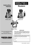
CONNECTING A LOOP DETECTOR (Optional)
A loop detector is a triggering device that can be placed under the ground inside the premises. The loop will
trigger the gate open when a vehicle drives over it. It is recommended that the DuraLoop ty pe detector is used on
y our D.A.C.E motor.
For more information on the installation of the loop, see the instructions supplied with the DuraLoop.
NOTE: multi—user mode must be selected when a loop detector is used. (Dipswitch 1)
Compact motor
Slot from edge of driveway to allow for cable entry
Loop wires buried in driveway
Wires from the loop to the motor.
See loop manufacturers wiring
specs
Anti-lift device. Stops the gate being lifted off the rail.
Auto-close. The gate will close automatically after a chosen time delay . (optional)
Battery . 12 volt 7 amp hour battery that drives the motor.
Calibration mode. Mode the motor is in after it has been placed in manual over-ride. (Compact 300 only )
Collision sensing / over current. In the case of a collision with an obstacle, the gate will stop.
Charger. Delivers a trickle charge to the battery .
End stop. Stops gate from running off the end of the rail and causing injury .
Foundation plate. Mechanism to anchor the motor to the ground.
Intercom. A hand set and a gate station that allows communication between the gate and the house. (optional)
Infra-red safety beams. Prevents the gate closing on an obstruction. (optional)
L.C.D. Screen. Indicates information regarding the operator status (Compact 300 only )
Magnet. Attaches to the gate to allow for accurate gate operation. (Compact 500 only )
Manual override. Allows the gate to be moved by hand.
Motor. Gate operator.
Multi-user. Allows the gate to open and will not accept any other trigger while opening. (optional)
Party -mode. Allows the gate to remain open even when auto-close is selected. (optional)
P.C. Board. Main control board containing all the electronic components.
Pedestrian mode. Allows the gate to open partially . (optional)
Pinion. The main gear that drives the gate on the rack.
Positive close. The gate will close flush with the closed end stop / post. ( this feature is pre-set on the Compact 300
and is an option on the Compact 500 )
Rack. Length of toothed ny lon gear that attaches to the gate.
Receiver. Radio receiver that receives a signal from the remote.
Remote. Hand held device that sends a radio signal to the receiver to open or close the gate.
Transformer. Reduces 220volts to 16 volts.
Test button / trigger. Button to operate the gate from the P.C. Board. Used during programming.
ABOUT THE BATTERY / MAINS POWER. It should be noted that the motor is battery operated. This means that the
motor will not operate with a flat battery or if the battery is removed from the motor. The mains supply is used to charge the
battery only . The mains will not operate the motor. In the case of a mains power failure, the battery will continue to operate
the motor until the battery runs flat. This should be about two day s under normal conditions. The Compact 500 has two
L.E.Ds on the front of the motor. One L.E.D. is green the other is red. The green L.E.D. must be on at all times, this indicates
that the mains is on. The red L.E.D. indicates that the battery is flat.
The Compact 300 has a L.C.D. screen. The screen will show “mains fail” if the mains is disconnected.
The screen will show “low batt” if the battery is going flat.
ABOUT OVER-CURRENT. When the gate is moving and it strikes an object, the software will detect the object. This will
cause the motor to stop. If the over-current is detected while the gate is closing, the gate will stop and then re-open in the
slow speed. If the over-current is detected while the gate is opening, the gate will stop and remain still. The gate will close
on the next trigger that it receives or after the auto-close time has expired. It should be noted that D.A.C.E. recommends the
use of DURATRONIC beams on all installations to minimise the chance of the gate closing while there is an object in its
ABOUT POSITIVE CLOSE. This means that the gate will close up against the end stop / gate post leaving no gap between
the gate and the post. This ensures that the electrical contacts of an electric fence make a solid connection when the gate is
closed. This is a pre-set function on the Compact 300. It is an optional function on the Compact 500. To set up positive close
on the Compact 500, simply program the motor with no magnet on the gate.
ABOUT AUTO-CLOSE. Auto-close can be set to make the gate close automatically after a chosen time period.
It must be noted that it is dangerous and D.A.C.E. strongly advise against the setting of auto-close without the use of
DURATRONIC infra-red safety beams.
Warning use a loop detector as a trigger only. Do not use as a safety device. Use beams
in conjunction with the loop at all times
24
ABOUT CALIBRATION MODE. (Compact 300 only)If the motor is placed into manual over-ride mode. The motor will
need to be operated 3 times after it has been re-engaged in operational mode. This is called the “Calibration mode” NOTE this
must not be confused with program mode. Calibration mode is done simply by operating the gate fully open and closed three
times. On the third operation the gate may go into slow mode, this is normal.
5
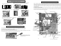
GENERAL MOTOR LAYOUT
CONNECTING AN EXTERNAL RECEIVER (OPTIONAL)
The pictures below show the Compact 500 and the Compact 300 motors. The lids have been removed to show greater
detail. The Compact 500 and Compact 300 share the same major components. The differences are shown in the pictures.
The Compact 500 is shown with the battery removed. The foundation plate, base, gearbox, electric motor, battery ,
P.C.Board and the lid are all shared parts by both motors.
Compact 500
Main P.C.Board
Main P.C.Board
Compact 300
Battery
(Marker / magnetic sensor
Compact 500 ONLY)
12V D/C
Electric motor
Receiver board
L.C.D. screen
(Compact 300 only)
Clear gearbox lid
Connect to
TRIG for full
opening or
connect to
PED for
pedestrian
opening
Charge L.E.D.
GREEN (Compact 500 only )
Low battery L.E.D.
RED (Compact 500 only)
Over-ride access door with lock
Bridge com and neg
The Compact 500 and the Compact 300 share the same foundation plate as shown here
Foundation
plate
Jack –up bolts and nuts used to
secure the motor to the foundation
plate
Holes in plate for conduit access
6
4 Holes for mounting
the plate to the concrete
using coach screws
NB the normally open (NO) connector is wired to the TRIG or PED
connector on the Main P.C.Board
To program remotes to the receiver.
1.
Press and hold the button on the remote.
2.
Place the jumper over the two TX LEARN pins for 1 second.
3.
Remove the jumper.
4.
Release the button on the remote.
Repeat the above steps for each remote to be programmed.
23
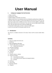
CONNECTING AN INTERCOM (OPTIONAL)
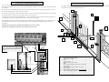
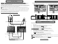
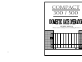
GENERAL SITE LAYOUT
There are many different ty pes of intercoms available on the market today .
The wiring of these intercoms can vary in some way s, but the general wiring is the same. The three main ty pes of intercom
are as follows:-
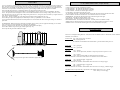
The diagram below shows a basic site lay out. Some items shown are optional extras. It should be noted that infra-red
safety beams are strongly recommended on all sites
220 volt. This ty pe normally plugs into the house mains, (220 volt supply ) Four wires are used on this sy stem. Two wires
go to the gate station and two wires go to the motor (trigger).
2
12 volt. This ty pe normally gets its power from the motor (12 v/dc). This means that a minimum of six wires are needed to
run from the handset. Two wires to the gate station and four wires to the motor.
6 volt. This ty pe is battery operated, normally using 4 x “AA” ty pe batteries for power. Only four wires are needed to run
from the handset. Two wires to the gate station and two wires to the motor (trigger)
7
1
The mounting of the intercom is the same with each ty pe. The handset is placed inside the house / office and the gate station is placed at the point of entry , this is normally at the gate. The gate station is normally mounted by means of a
“gooseneck”
It is important to note that the communication cable MUST be run in a conduit.
DO NOT run communication cable in the sa me conduit as any 220 v cable.
9
12
3
4
11
5
11
6
Diagram shows a ty pical Kocom 12 volt
one to one intercom sy stem. Other brands
may vary in the layout of the connector
screws.
22
10
TO 12 V
To GND
TO TRIG
1.
2.
3.
4.
5.
6.
7.
8.
9.
10.
11.
12.
End stop minimum 70mm high
Anti-lift device / rollers.
Rail.
Compact motor.
Magnet. (Compact 500 ONLY)
Rack.
Goose neck with intercom gate station. (Optional.)
Catch bracket.
DuraOptic Infra-red safety beams. (Optional.)
80mm wheels.
7
Conduit carry ing electrical cables. 12-16volts only
Pillar courtesy lights. (Optional)
8
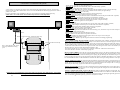
SITE EVALUATION
WIRING AUXILIARY EQ UIPMENT
The site should be evaluated before the installation begins. The following items should be checked.
1.
Flood level. The motor should be above flood level to avoid any damage to the motor.
2.
The rail must be level and should be above ground level, this will assist with keeping debris out of the path of the
wheels. Any debris ly ing on the rail may cause the motor to over current or blow a fuse.
3.
Trees and growth. Any over grown trees and bushes should be cleared to allow the gate to operate smoothly .
All auxiliary equipment should be connected with caution as an incorrect connection could lead to the P.C.Board
being damaged. Consult the wiring diagrams below. All power should be removed from the P.C.Board. before any
connections are made.
WIRING DURATRONIC INFRA-RED BEAMS (RECOMMENDED)
NB Beams shown with front
covers removed.
Covers must be in place when
beams are active. Ensure that the
correct cover is replaced onto the
correct beam. As this may cause
faulty operation if the covers are
incorrect.
Mount the motor above the flood
level or a flood proof wall must be built in order to retain
any water from entering the motor
The rail should be above ground level.
+
+ - C NC
MAIN P.C.BOARD
The gate must not move on its own when left in any position along the rail, if this does occur, the rail must be leveled
before the gate is automated.
Ensure that the rail is kept clear of all debris as failure to do so may lead to the gate jamming . This may lead
to motor over-current or blowing fuses.
12 VOLT
GROUND
INF JUMPER on the main PCB
To be removed before beams are connected.
Keep all trees, branches, bushes and other growth clear of
the gate. Failure to do this may lead to the gate jamming.
Note although the installation of infra-red safety beams does reduce the risk of the gate
striking an object while closing it does not guarantee against it.
8
21
GATE EVALUATION
SETTING AUTO-CLOSE (OPTIONAL)
It is extremely important to evaluate the gate that is to be automated before any automation is done. The following
points must be checked. All of the points mentioned below are common causes of gate problems if not checked.
Auto-close is an option that allows the gate to close automatically after a chosen time delay , this delay can be from 10
to 70 seconds. Auto-close is selected by using the dipswitches on the main P.C.Board. Dipswitch numbers 2,3 and 4
are the auto-close time select switches. The times are as follows. 2 off 3 off 4 off = no auto close.
2 on 3 off 4 off = 10 seconds
2 off 3 on 4 off = 20 seconds
2 off 3 off 4 on = 40 seconds
2 on 3 on 4 on = 70 seconds
Any combination can be used to select the desired auto-close time.
NOTE It is strongly recommended that DuraOptic safety beams are used when auto-close is selected as this
reduces the chances of the gate closing on an object and causing injury or damage.
Check the start up force of the gate using a fishing scale .
Maximum start-up force
(Compact 500 = 10 kg)
(Compact 300 = 6 kg)
PULL
Ensure that the rail is level.
The gate must not move on its own when left in any position on the
rail.
Dipswitches 2 , 3 and 4 are used to select auto-close times
Ensure that the end stops are secure.
Recommended 70mm high
SETTING PARTY MODE (AUTO-CLOSE OVER-RIDE)
Party mode is the auto-close override mode. This means that the gate will remain open and ignore the auto-close
time.
To set party mode :
1.
Press and hold the remote button down for 15 seconds. The gate is now in party mode.
Note the gate will start to open as soon as the button is pressed, this is normal.
To reset the gate to normal operation mode:
1.
Press the remote button twice within two seconds.
The gate will start to close. The gate is now in normal operation mode .
Ensure that the wheels are turning freely.
Recommended 80mm wheels.
It is recommended that 16mm round bar is used to assist with
the smooth operation of he gate.
Rollers must roll freely .
The roller mounting can be used as an anti-lift device,
SETTING MULTI-USER MODE (OPTIONAL)
Multi-user mode is used in heavy traffic areas where there is a possibility that a number of triggers are received by
the motor at one time. eg office block or town house complex. When multi-user mode is set, the motor will accept
the first trigger and ignore any other trigger thereafter, this reduces the chance of the gate closing on an object.
Although the Compact motor is designed to be used in a domestic application only , this function is available.
To set multi-user mode, place number 1 dipswitch in the ON position.
To disengage multi-user mode, place number 1 dipswitch in the OFF position.
NOTE !!! If Multi-user is selected, an auto-close time must also be selected. If an auto-close time is not selected,
the gate will immediately close after opening.
Number 1 dipswitch used to select multi-user mode
In the case of the rollers coming off the mounting,
the gate must remain in an upright position.
A device must be fabricated to allow for this.
If the gate has a full portal, the portal will provide
for this.
20
9
The gate must not jam in the catch bracket when
opening or closing as this may cause the motor to
over current.
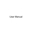
PROGRAMMING REMOTES
REMOVING THE LID AND PLACING THE MOTOR IN MANUAL OVER-RIDE
Unscrew the two screws at the side of the lid
To program remotes to the on-board receiver complete the following steps. It is recommended that the remotes are
numbered in order of programming. This will assist with erasing any lost or stolen remote at a later stage
Step 1. press and hold the button on the remote.
Step 2. place the jumper over the two pins on the P.C.Board called TX- L for 2 seconds.
Step 3. remove the jumper from the two pins.
Step 4. release the button on the remote.
The remote is now programmed to the receiver.
Repeat the above steps for each remote to be programmed to the receiver. Max 15 remotes.
Press and hold button
1
Place jumper on TX- L
2
Remove jumper
3
Release button
4
To place the motor into manual Over -ride:•
Open the door
•
Turn the thumb-wheel clockwise until the gate is free to move.
IMPORTANT !!! take note of the gate position before over-riding. (Compact 300 only)
ERASING ALL THE REMOTES FROM A RECEIVER.
1.
Insert the jumper over the two pins called TX- E
2.
Count 4 flashes of the green LED next to the test button on the main PCB
3.
Remove the jumper
4.
Replace the jumper and count two flashes
5.
Remove the jumper.
6.
Replace the jumper and count four flashes
7.
Remove the jumper
The led will flash rapidly to indicate that the remotes have been erased from the receiver.
To place the motor into Operational mode:•
Place the gate in the same position as it was in before.
•
Turn the thumbwheel anti-clockwise while moving the gate . The gate will lock into place. It is important that the
gate is moved while the thumbwheel is turned as this allows the motor to re-engage.
•
IMPORTANT.!!! Compact 300 only. The gate must always be operated THREE (3) times after it has been
placed bac k
into operational mo de. This is called Calibration mode, it allows the gate to re-calibrate the end stops.
10
ERASING A SINGLE REMOTE FROM THE RECEIVER.
To erase one single remote from the receiver, the remotes need to be numbered in order of programming. This
means that each remote must be given a number before being programmed to the receiver.
If this has been done then it is possible to erase a single remote. The preceding remote will erase the remote
above it. For example remote number 6 will erase remote number 7 etc.
1.
Place the jumper over the TX--E pins.
2.
Press the button of the remote preceding the remote that is to be erased.
3.
Remove the jumper.
The remote will now be erased. The next remote to be programmed will take the place of the erased remote.
19
PROGRAMMING THE MOTOR
P.C.BOARD LAYOUT
1. Open the gate manually 1m.—1.5m
2. While turning the thumb wheel anti clockwise, move the gate
slightly until a click is heard and the motor locks into place
1m
3. Place the jumper over the “PROG” pins
4. Apply battery power.
Do not reverse polarity
5. Press the test button once
The P.C. board is a sensitive piece of electronic equipment. All electronic equipment should be handled with care. Never
connect or remove wires on a P.C.Board while there is power on the board as this may lead to damage. Never touch the
board with any metal object. Never allow the board to get water on or near it as this may lead to corrosion. No insecticide
or other spray s should be used on a P.C.Board. Do not attempt to repair the P.C.Board. Any repairs must be carried out by
an authorized agent.
Do not apply 220volts to the board. (16 volts AC and 12 volts DC only ). Never reverse the polarity of the battery wires as
this will lead to extensive damage.
The charger circuit on the P.C.Board has a rectifier which converts AC voltage to DC voltage, this will generate some
heat on the rectifier heat sink., care should be taken that no wires touch the heat sink as this may cause the plastic insulation of the wire to melt and may lead to a short circuit.
Receiver
Light / lock connector
L.C.D. connector
Marker connector
(Compact 500 only)
8. Apply 16 volt AC power
Current sensing pots
7.When the motor is fully open, remove the PROG jumper.
The motor is now fully programmed
Battery wires
Red and black
Auxiliary connectors
SETTING THE OVER-CURRENT
Earth wire
Green and y ellow
Over-current is the amount of force that the motor delivers before stopping when an object is struck.
The amount of force is controlled by the two potentiometers (pots) found on the main P.C.Board.
To increase the amount of force turn the pots clockwise.
To decrease the amount of force turn the pots counter clockwise.
Set the current sensing pots according to the gates weight. Do not set them too high, as increasing the current sensing
may cause serious injury or damage in the case of the gate striking an object
16 volt AC connector
from transformer
20 amp motor fuses
L.E.D. extension connector
Using a small flat screwdriver turn the
pots to increase or decrease the current
sensing of the motor
Test button
Dipswitches
18
Infra red jumper
Motor wire connectors
11
Open / close / status L.E.D.
Program jumper
Learn / erase remote jumpers
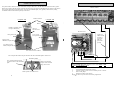
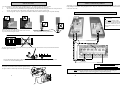
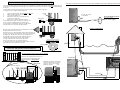
ELECTRICAL WIRING
SETTING THE MOTOR DIRECTION
WARNING!!!: Danger of electrical shock is poss ible while connecting the wiring on this equipment.
Take special care when connecting any electrical wires. Ensure that ALL power is switched off or isolated before any
connections are made. This equipment is supplied with a 16 volt AC transformer. Do not open or tamper with the
transformer as this could cause electrical shock.
The transformer delivers a 16 volt AC out-put to the charger on the main P.C.Board. This 16 volt supply will keep the
battery charged. The battery operates the motor. In the case of mains power failure, the battery will continue to operate the
motor as normal until the battery goes flat. The motor will then stop operating.
Note: this is a battery operated motor and will not operate with a flat battery regardless of the mains supply being
switched on.
The 16 volt AC wiring from the transformer in the house to the charger on the main P.C.Board must be run in a conduit
from the house to the motor. The conduit must terminate inside the motor. No joins in the cable should be made between
the transformer and the motor.
The cable used to run the 16 volt AC from the transformer to the charger should be a minimum of a three core 1.5mm
cable. The conduit should have no sharp bends in it as this may cause problems in the future if the cable needs to be
pulled out and replaced. The conduit should be buried 300mm underground.
The following diagrams show the correct wiring of the electric motor to the main P.C.Board. The motor wires are found
protruding from the motor, there are two wires, one wire is blue in colour the other wire is black in colour.
FOR A GATE CLOSING TO THE LEFT
FOR A GATE CLOSING TO THE RIGHT
BLACK WIRE
DO NOT RUN 220 VOLTS IN THE SAME CONDUIT AS 16 VOLTS.
BLUE WIRE
BLUE WIRE
BLACK WIRE
COMPACT 300 WIRING
Closing direction
Closing direction
PROGRAMMING THE MOTOR
The motor must be programmed to the gate in order to operate correctly . .
It is important to note that the following points should be checked before the gate is programmed.
Transformer
16 VOLTS AC
Main P.C.Board
16 VOLTS AC
EARTH
12
Connect the E (earth) from the transformer to the
green and yellow wire on the main P.C.Board.
1.
2.
3.
4.
5.
Motor is level.
Rack is secure to the gate and engaged with the pinion gear.
The gate has adequate end stops. (DO NOT automate a gate without end stops.)
The gate runs freely and does not jam at ANY part of travel.
The magnet is mounted correctly . (Compact 500 only)
TO PROGRAM THE MOTOR. Ensure that all power is removed from the board.
1.
Manually open the gate 1m -1.5m This will be the pedestrian opening distance.
2.
Lock the gate in place. (Operational mode.)
3.
Insert the program jumper over the two pins on the P.C. Board called “prog motor”.
4.
Apply the battery power. The status L.E.D. will flash rapidly .
5.
Press the trigger button. on the P.C.Board. The gate will automatically do the following
6.
A) Close slowly until the end stop is struck.
B) Open slowly until the end stop is struck.
7.
When the motor is fully open. Remove the jumper from the prog motor pins.
8.
Apply the AC mains power and ensure that the green “charge” led comes on.
The motor is now fully programmed and ready for normal use.
NOTE the programming procedure can be aborted at any stage simply by removing the battery wires. This will stop the motor
and the process can be re-started at any time.
In step (6 A) the gate must close first. If the gate opens first, then the motor wires must be reversed. This will change the
motor direction. {See17
Setting the motor direction}
Do not connect any other trigger wires to the board until the motor is fully programmed.
PTO for programming diagram.
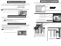
MOUNTING THE RACK
ELECTRICAL SHOCK MAY OCCUR. PLEASE TAKE EXTREME CARE WHEN WIRING THE TRANSFORMER
The rack is attached to the gate using the TEK screws supplied. It is recommended that the rack is not welded to the gate
as this prevents any adjustment at a later stage. The rack must mesh with the pinion gear throughout the complete length
of the gate.
A 2mm gap between the pinion gear and the rack should be set. This avoids any tight spots.
To mount the rack, complete the following steps.
1.
2.
3.
4.
Open the gate manually . The gate must be fully open.
Place a length of rack on the pinion.
Insert the first TEK screw.
Roll the gate to the next mounting hole and
insert the next TEK screw.
5.
Repeat step 4 until the complete length of
rack is attached to the gate. The rack may need to be cut
if any section is protruding from the end of the gate.
It is important to ensure that the rack stay s in full contact
with the pinion gear at all times during mounting
RACK
16 V/AC OUT-PUT
To P.C.Board
TEK
DANGER HIGH VOLTAGE
220 V/AC IN-PUT
screw
From mains supply
COMPACT 500 WIRING
Move the gate by hand until the next mounting hole is above
the pinion and then insert next screw.
When the process is complete and the rack is attached securely to
the gate, the motor must be adjusted to allow a 2mm gap between
the pinion gear and the rack. The best way of doing this is by
dropping the motor 2mm on the bolts. Push the gate open
and closed by hand to ensure that the rack is adjusted
correctly . Check that the rack is not too tight or too
loose on the pinion gear. If it is found to be loose
or tight, the rack must be adjusted accordingly . Failure to do this
may result in incorrect operation of the gate.
2mm gap
MOUNTING THE MAGNET (COMPACT 500 ONLY)
Do not install the magnet if positive close is required.
700MM
Main P.C.Board
Measure 700- 800mm from the motor and
mount the magnet. This must be done
with the gate in the closed position.
Gate motor
Do not invert the magnet.
Transformer
Maximum gap between the magnet
and the motor must be 3mm. If the
gap is not correct, place washers
behind the magnet.
3mm
700-800MM
EARTH
16
13
16 VOLTS AC
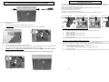
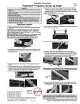
ANCHORING THE MOTOR
SECURING THE MOTOR TO THE FOUNDATION PLATE
It is very important that the motor is mounted on a firm foundation that can not move or become loose over time. The
foundation should be constructed from concrete. The size of the plinth should be about 300 x 300 mm square and about
200mm deep. The foundation plate supplied with the motor must be securely mounted to the concrete using coach
screws and plugs. The foundation plate can also be welded to the gate rail if need be. The concrete should be allowed
sufficient time to set before the motor is mounted onto the plate.
For a gate closing to the right
For a gate closing to the left
W hen anchoring the motor it is important to ensure that the following points are checked.
1.
2.
3.
4.
5.
The electrical cable is in place.
The concrete is fully set.
The motor foundation mountings are secure and can not move or become loose.
The motor should be set level and parallel to the gate.
The motor must be set above the flood level or if this is not possible, a flood proof wall should be constructed
around the motor.
Top view
After placing the motor onto the three jack-up
bolts, place the three clamping nuts and washers
over the bolts to clamp the motor in place. Use the
Nut Applicator as shown below.
Anti-lift device and
Rollers
P.C.B.
Place concrete plinth here
1
Place concrete plinth here
Nut Applicator.
2
Dig a hole about 300mm square
Insert the nut into the applicator
Place the conduit in the correct position before filling the
hole with concrete. Flexible conduit may also be used.
3
Foundation plate
4
Side view
Use 8 mm coach screws to
mount the foundation plate to
the concrete
Allow concrete to set and then place the
foundation plate onto the concrete plinth
P.C. Board
Conduit
Trim the conduit and the cable to the correct length
before placing the motor onto the foundation plate.
Place the nut on the bolt
Side view
Foundation plate
Gate
Top view
Foundation plate
Concrete plinth
Jack-up nuts
for adjusting the
motor height.
Tighten the nut with a spanner.
Ensure that the motor is mounted level
8mm coach screws in plugs
35mm
14
15