1
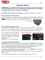
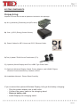
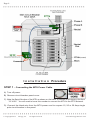
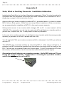
Installation
Manual
for
TED Pro Home
AB
C
Rev 2.1
IMPORTANT:
The installation of your TED Pro Home system is a several-step
process. The 1st step is the installation of the MTU Home. After
the MTU Home is installed, Step 2 is the installation of the ECC,
and the last Step ... Footprints software.
If the equipment is used in a manner not
specified by the manufacturer, the protection
provided by the equipment may be impaired.
TA B L E O F C O N T E N T S
PART I Introduction . . . . . . . . . . . . . . . . . . . . . . . . . . . . . . Page 2
Quick Start . . . . . . . . . . . . . . . . . . . . . . . . . . . . . . Page 3
Operating Conditions . . . . . . . . . . . . . . . . . . . . . . . Page 4
Limitations . . . . . . . . . . . . . . . . . . . . . . . . . . . . . . . Page 4
System Components . . . . . . . . . . . . . . . . . . . . . . . . Page 5
PART II Safety . . . . . . . . . . . . . . . . . . . . . . . . . . . . . . . . . . Page 6
PART III Installation . . . . . . . . . . . . . . . . . . . . . . . . . . . . . . Page 7
PART IV Testing . . . . . . . . . . . . . . . . . . . . . . . . . . . . . . . . Page 11
PART V Footprints Software Installation . . . . . . . . . . . . . . . Page 12
Appendix
Appendix A - Wind/Solar Installation . . . . . . . . . Page 14
Page 3
*****************************************
Quick Start
IMPORTANT: Quick Start instructions are a summary of the main aspects of
MTU installation, and not to be considered a replacement for the complete
Installation Instructions contained in this Manual.
For MTU power cable connection, reference drawing on Page 8.
CTs (Current Transformers):
Clip CTs around the conductor for each phase, with RED polarity dot facing
source of power, i.e. the utility. If loads are displayed as a negative number on
Footprint’s Dashboard, swap A & B CT-inputs on the MTU.
Data Communication - PLC
The method of communication is PLC (Power Line Carrier). If possible,
plug ECC into a Phase A outlet. After the ECC has been configured with
MTU ID, the PLC Link LEDs should turn solid green within 3-5 minutes.
It is very important that the Installer
verify operation before leaving the
site by checking LINK LEDs and
verifying reading on Footprints
Dashboard.
(See Page 11 for more diagnostics)
MTU Link LED
ECC Link LED
Accessing TED FOOTPRINTS
Plug Ethernet cable from ECC to router or network drop. Most Browsers (Internet
Explorer, Chrome, etc.) will recognize the ECC by typing “TED6000” into the address
bar and pressing ENTER. If this does not open the Footprints page on your Browser,
go to the TED website to Download and RUN the TED Installation Utility:
http://www.theenergydetective.com/downloads-documents
This utility will detect TED devices on your Network. Select “TED6000” when it appears
in the window and click LAUNCH IN BROWSER.
Note: For details on Footprints settings, download the ECC User’s Manual from the
TED website.
http://www.theenergydetective.com/downloads/ECCUsermanual.pdf
*****************************************
Rev 2.1
Page 4
****************************************
PA R T I – I N T R O D U C T I O N
SAFE OPERATING RANGE AND CONDITIONS:
Use
Condition
Temperature
Relative Humidity
Altitude
Voltage
Maximum Power
Display &
ECC
MTU & CTs
Indoor
Dry
+10° +40°C
< 80%
3,300M
95-277 VAC
5W
Indoor/Outdoor
Dry /Damp
- 40°C to +50C
< 95%
3,300M
200-500 VAC
1.5W
Limitations
Please note the following limitations:
• MTU Home is suitable for use on 50 or 60 Hz, single phase services around the world up
to 277V.
• MTU Home utilizes Power Line Communication (PLC) to transmit Energy data to the ECC.
If you require Ethernet communication for your application, please use MTU Pro.
• MTU Home is also suitable for use with solar/wind generation systems. You will need to
purchase one additional MTU Home. When installed it will tell you Load, Generation and
NET metering.
• MTU Home is suitable for use on single-phase services up to 400A.
o For services >200A optional accessories are required. See website for details.
o Accuracy when used on single-phase services is better than ±2%
• MTU Home is suitable for use on single-phase services derived from 3-phase) up to 200A.
o Accuracy when used on 3-phase services is better than ±5%.
o For 3-phase services you will need to purchase one additional CT.
o TED will not work on 3-phase services.
o For 3-phase services, see specifications for TED Pro MTU and TED Pro Lite MTU at
www.theenergydetective.com
*****************************************
© Copyright 2014
Energy, Inc.
All rights reserved
www.theenergydetective.com
Page 5
*****************************************
SYSTEM COMPONENTS
Unpacking
Unpack TED and ensure that all parts are included in the package.
A) One (1) Measuring Transmitting Unit (MTU Home)
B) One (1) ECC (Energy Control Center).
C) Power Cables for MTU Home and, ECC; Ethernet Cable.
D) Two (2) Model CT601B Current Transformers (CT’s)
E) (Optional) Wired Display and Flat, USB3 Type Data Cable
F) (Optional) Wireless Display, Stand, Power Adapter, and USNAP Zigbee
Wireless Card seated firmly in bottom of ECC.
G) Installation Manual - Please Read Carefully
If you received the optional Wireless Display, let’s get the battery charging:
- Plug the power adapter into a wall outlet
- Connect the power cable to the charging stand.
- Remove battery tab.
- Install Display into charging stand.
*****************************************
Rev 2.1
Page 6
****************************************
PA R T I I – S A F E T Y
The Installation of TED is intended for professional electricians or
highly technical home owners only.
This brief manual summarizes the steps necessary to safely install the MTU and Current
Transformers (CTs). For detailed installation and operation of other components and software,
please refer to the HELP Section of the TED Footprints Software, or see Support at:
www.theenergydetective.com
Every effort has been made in providing for the safe, secure installation of TED. The installation of
TED requires the cover of the main electrical circuit breaker panel to be removed. After the circuit
breaker panel cover has been removed, the potential hazard of shock, burn, or even electrocution
now exists. Do not attempt to complete this installation unless you are a licensed electrician familiar
with the electrical components and operation of the circuit breaker panel. Even when the main circuit
breaker has been turned to the “OFF” position, certain areas within the circuit breaker panel may still
be electrified. Do not attempt installation unless you know where these electrified areas are.
This symbol will be found throughout
the instructions where there is a potential for electric shock, burn, or even
electrocution. Do not attempt to complete the noted section if you are not
an electrician, or qualified installer.
WARNING - These servicing instructions are for use by qualified personnel only. To reduce the risk of
electric shock, DO NOT perform any servicing other than that contained in these operational instructions
unless you are qualified to do so.
WARNING - The MTU must be connected to a switch or circuit breaker in close proximity to the equipment
and within easy reach of the operator. It must be marked as the disconnecting device for the MTU.
WARNING - If the equipment is used in a manner not specified in these instructions, the protection
provided by the equipment may be impaired.
Energy, Inc. Model TED6000 / TED Pro
Home
TESTED TO COMPLY WITH
FCC STANDARDS
FCC Part 15 SubPart B
EU/EN 61326-1
FOR HOME AND OFFICE USE
This device complies with part 15 of the FCC Rules.
Operation is subject to the following two conditions:
(1) This device may not cause harmful interference,
and (2) This device must accept any interference received,
including interference that may cause undesired operations.
*****************************************
© Copyright 2014
Energy, Inc.
All rights reserved
www.theenergydetective.com
Page 7
*****************************************
PA R T I I I – I N S TA L L AT I O N
B E F O R E Y O U S TA R T
• Do not begin installation until you have read the “Safety” section of this manual.
• Read all instructions before beginning installation.
Estimated Installation Time:
Professional Installer: 15 minutes
Equipment Needed:
- Flathead screwdriver - small and large
- Phillips screwdriver - small and large
- Flashlight
Important Notes:
- For services with Wind/Solar or Standby Generator, an additional MTU will be required to measure
GENERATION and NET.
- All wiring in the United States must be installed in accordance with the latest adopted edition of the
National Electrical Code (ANSI/NFPA 70, NEC) and state or local requirements.
- All wiring in Canada must be installed in accordance with the latest adopted edition of the Canadian
Electrical Code (CSA C22.2 CEC, Part I) and any provincial or local requirements.
- Wiring in other countries and jurisdictions should be done in accordance with the rules and regulations in
effect for the installing location. Contact your local power authority or local regulator for more information.
- Turn off all power to the circuit breaker panel by turning off the main breaker or main switch.
Definitions:
- MTU – Measuring Transmitting Unit
- ECC – Energy Control Center
- DISP – LCD Display
*****************************************
Rev 2.1
Page 8
****************************************
I n s t a l l a t i o n Procedure
STEP 1 – Connecting the MTU Power Cable
A) Turn off power.
B) Remove circuit breaker panel cover.
C) Note the Serial Number of the MTU as shown on the label. It consists of six digits in the form
“12 34 56.” You will need to know this number to connect the MTU to the ECC Network.
D) Connect the black wire from the MTU power cord to a spare 15, 20 or 30 Amp single
pole circuit breaker in the panel.
*****************************************
© Copyright 2014
Energy, Inc.
All rights reserved
www.theenergydetective.com
Page 9
*****************************************
E) If there is no spare circuit breaker, the black wires can be attached to any 15, 20 or 30 Amp
single pole circuit breaker in the panel, provided that the circuit breaker is approved for
2 conductors and this is acceptable to the “authority having jurisdiction in the installation
location” (it is generally acceptable);
NOTE: For optimal PLC Communication, the ECC must be plugged into a circuit on
the same phase as the black wire on the MTU power cable. (If your readings
display as negative, swap A & B CT-inputs on MTU.)
F) Connect the white wire from the MTU to the neutral bus on the panel.
G) Do not connect the Power Cable to the MTU until you have the CTs connected.
STEP 2 - Installing and Connecting the Current Transformers (CTS)
A) CAUTION – IF THIS IS A COMBINATION PANEL, THE LUGS ON THE PRIMARY SIDE OF
THE MAIN BREAKER ARE PROBABLY STILL HOT.
B) Determine what type of system you have.
i. Split single-phase 3-wire. Common in North America residential and
small commercial buildings. There will be 2 power wires (usually black
and red) and one neutral wire (usually white). Voltage from the power wires
to neutral will be approximately 120V, Voltage from one power wire to the
other will be double that, approximately 240V.
Install 2-CTs, one over each of the power wires and plug into A & B ports on the MTU.
ii.Single-phase 2-wire. Common in Europe and many other countries. There will be one
power wire (usually black or brown) and one neutral wire (usually white or blue).
Install one CT over the power wire and plug into A port on the MTU.
iii. Single-phase derived from 2 phases of a 3-phase system. (Sometimes called 2-phase).
Typical in apartment or office buildings, common in many countries. Same as 3-phase
except only 2 of the 3 phases are brought into the building or panel.
Install 2-CTs, one over each of the power wires and plug into A & C ports on the MTU.
Note 1: The CTs should be installed on the secondary side of the main switch or main circuit
breaker, however, if this is not possible, such as in the case of a combination breaker
panel, then install on the primary side of the main breaker.
Note 2: The CTs must be installed with the red polarity dots facing towards the source of power
(toward the utility meter or toward the generator of inverter if measuring generation).
Note 3: Do not install the CT over the neutral (N) (grounded) conductor..
Note 4: If you have solar, wind or standby generator, you will need an additional MTU if you
want to measure: Generation, Load and Net Utility. Please see solar/wind section of our
website for details.
*****************************************
Rev 2.1
Page 10
****************************************
Note 5: To install the CT:
• Open the CT by lifting the locking tab on the side of the CT, over the restraining clip.
• Place the CT over the cable and close the locking tab.
• Insure that it is properly seated and the CT will not open with a gentle pull.
(The CT will likely be loose around the wire - this is fine)
STEP 4 - Installing the MTU
A) Plug the power cord into the MTU
B) Determine the best location to mount the MTU.
i. Choose a location where it will not interfere with existing equipment or wiring.
ii. The MTU may be attached using double-sided tape (if allowed in your jurisdiction),
or with sheet metal or machine screws.
C) Arrange and tie-wrap all wiring in a neat and tidy manner.
D) Turn on the power.
NOTE: If you have more than one MTU, only power up one at a time. If you have a solar
installation, do not power up the solar MTU now. See Appendix A.
LEDs will begin to blink on the MTU
Do not close the electrical panel until you have completed the installation of the
ECC and verified that correct data is being received from the MTU.
Close the Electrical Panel only after you have confirmed the correct operation of the TED
Pro system.
*****************************************
© Copyright 2014
Energy, Inc.
All rights reserved
www.theenergydetective.com
Page 11
*****************************************
PA R T I V – T E S T I N G T H E S Y S T E M
NOTE TO PROFESSIONAL INSTALLER:
Even if the customer chooses to configure the ECC, display and network, it is extremely
important that the installing electrician verify correct operation and measurement prior
to leaving the site. This can be done with an optional Display or using a laptop computer
and Footprints software.
MTU and ECC are paired at the factory and will begin to communicate on power-up. If not
you may need to input the MTU ID in System Setup. Refer to website for ECC operation
manual.
1.ECC
- Plug ECC into suitable outlet. Do not choose an outlet that has a lot of electronic or
computer equipment plugged into the same outlet. Insure that the MTU and ECC are
connected to the same phase.
2.DISPLAY (optional equipment).
a. Wireless Display
• Plug power supply into suitable outlet. Connect power supply outlet to back of
charging stand.
• Remove battery protection tab from Display.
• Plug Display into charging stand.
b. Wired Display (Refer to Appendix C of ECC User Manual)
• Remove power from ECC
• Plug Display cable into rear of Display
• Plug other end of cable into Display port at rear of ECC
• After connecting Display, cycle power on ECC by unplugging/reinserting AC cord
into wall outlet.
3.Check operation of Power Line Communication (PLC) Status LEDs.
MTU – There are two LEDs on the front of MTU
o Bottom LED – Link
- Will blink on power-up.
- Will turn solid green when linked to ECC – Single-phase
- Will turn solid red when linked to ECC – Three-phase/Two-phase
o Top LED – Send/Receive
- Blinks green when receives data from ECC
- Blinks red when transmits date to ECC
- In normal operation it will be constantly flashing red and green.
ECC – There are two LEDs on the left side of the ECC
*****************************************
Rev 2.1
Page 12
****************************************
o Rear LED – Link
- Will blink on power-up.
- Will turn solid red when network established
- Will turn solid green when ECC is linked and receiving data from at least one
MTU
o Front LED – Send/Receive
- Blinks green when receives data from MTU
- Blinks red when transmits date to MTU
- In normal operation it will be constantly flashing red and green
TEST USING DISPLAY
Once installed, you should see values for kW demand and $ per/hour on the screen (default
energy rate is $0.10 per kWh).
- Turn on a known load (example 1200w microwave, Display should increase by 1.2kW)
- Turn on a known 240V load (example an electric oven: Display should increase by a
few kW. If it goes down, or only goes up by a few watts, then you have one of the CTs
reversed. Make sure that the red dots are all facing towards the power source).
TEST USING FOOTPRINTS SOFTWARE
NOTE: Once the Footprints Dashboard is accessed via one of the methods below, the
User should review the additional documentation and information under the “HELP”
button, or download the User’s Manual here:
http://www.theenergydetective.com/prodocs
Direct PC Connection: For further detailed assistance visit:
(www.theenergydetective.com/tedprocomputer)
- Connect ECC to installer laptop with Ethernet cable.
- Insure that IP address of Ethernet adapter is set at 192.168.7.1 (refer to Appendix A of
User’s Manual for network support)
- In your web browser type “192.168.7.4” in the address bar.
- Should load footprints software and show power readings on the speedometer of the
dashboard.
- If not, verify PLC Status LEDs and MTU ID in System Settings. Disconnect / reconnect
MTU from MTU Power Cable.
- Repeat load tests shown above.
Connection via customer’s router (if you are owner or have access to customer’s network)
Here is a link for assistance: http://www.theenergydetective.com/tedprorouter
- Connect ECC to router with Ethernet cable.
- Insure that IP address of Ethernet adapter is set at DHCP on owner’s computer network
*****************************************
© Copyright 2014
Energy, Inc.
All rights reserved
www.theenergydetective.com
Page 13
*****************************************
(refer to website for network support)
- In your web browser type TED6000 in the address bar, or run Installation Utility to
locate TED on the local network. To download Installer:
http://www.theenergydetective.com/downloads-documents
- Should load Footprints software and show power readings on the speedometer of
the Dashboard.
- If not, Verify PLC status LEDs and MTU ID in System Settings. Disconnect / reconnect
MTU from MTU Power Cable.
- If the loads on Dashboard are negative (and there is no Solar generation) switch the
A & B CT-inputs on the MTU.
- Repeat load tests shown above.
*****************************************
Rev 2.1
Page 14
****************************************
Appendix A
Solar, Wind or Auxiliary Generator Installation Addendum
Installing the Solar/Wind, or Auxiliary Generator components (“Solar” for short) needs to be
completed after the installation instructions have been followed for the installation of MTU 1
(beginning on page 6 of this Instruction Guide).
Assuming that you have successfully installed MTU 1 as detailed above, it is time to connect
MTU 2 to your Solar system. While there are many different variations in Solar connections,
we are presenting the installation of MTU 2 in the most common scenario.
Solar panels connect to an inverter which changes DC to AC. In most cases it will be
120/240V. The connection can tie into the main switch/Circuit Breaker, a transfer switch, a
junction box, a splitter box, etc. It really doesn’t make any difference.
In the case of an auxiliary generator, it will likely tie into a transfer switch because generally
speaking, a generator is not run in parallel with the utility.
You will use both CTs if your inverter connects via 240v...otherwise, if it is 120V, you will only
use one CT.
The MTU/CTs are connected similarly as connecting MTU 1. (See image on Page 8). If
possible, both MTUs should be powered from the panel on the same circuit or phase as the
ECC. This will give the cleanest Power Line Carrier signal. (Try NOT to power the MTU from
the inverter, as there will be a lot of line noise that could interfere with the signal).
Generation should display as a negative number. Verify RED dots on CTs are
facing the source of power. If Generation is showing as a positive number,
switch the A & B inputs on the MTU.
*****************************************
© Copyright 2014
Energy, Inc.
All rights reserved
www.theenergydetective.com
Page 15
*****************************************
NOTES
*****************************************
Rev 2.1
648 Marina Drive
Charleston, South Carolina 29492
(843) 766-9800
(800) 959-5833
www.theenergydetective.com