1
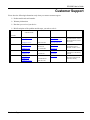
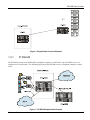
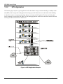
IES-2000
Integrated Ethernet Switch
Version 2.00
February 2003
User’s Guide
IES-2000 User’s Guide
Copyright
Copyright © 2003 by ZyXEL Communications Corporation.
The contents of this publication may not be reproduced in any part or as a whole, transcribed, stored in a retrieval
system, translated into any language, or transmitted in any form or by any means, electronic, mechanical, magnetic,
optical, chemical, photocopying, manual, or otherwise, without the prior written permission of ZyXEL
Communications Corporation.
Published by ZyXEL Communications Corporation. All rights reserved.
Disclaimer
ZyXEL does not assume any liability arising out of the application or use of any products, or software described
herein. Neither does it convey any license under its patent rights nor the patent rights of others. ZyXEL further
reserves the right to make changes in any products described herein without notice. This publication is subject to
change without notice.
Trademarks
Trademarks mentioned in this publication are used for identification purposes only and may be properties of their
respective owners.
ii
Copyright
IES-2000 User’s Guide
Interference Statements and Warnings
FCC
Interference Statement:
This device complies with Part 15 of the FCC rules. Operation is subject to the following two conditions:
(1) This device may not cause harmful interference.
(2) This device must accept any interference received, including interference that may cause undesired operations.
FCC Warning!
This equipment has been tested and found to comply with the limits for a Class A digital device, pursuant to Part 15
of the FCC Rules. These limits are designed to provide reasonable protection against harmful interference in a
commercial environment. This equipment generates, uses, and can radiate radio frequency energy and, if not
installed and used in accordance with the instruction manual, may cause harmful interference to radio
communications. Operation of this equipment in a residential area is likely to cause harmful interference in which
case the user will be required to correct the interference at his own expense.
CE Mark Warning:
This is a class A product. In a domestic environment this product may cause radio interference in which case the
user may be required to take adequate measures.
Taiwanese BSMI A Warning:
Certifications
Refer to the product page at www.zyxel.com.
Interference Statements and Warnings
iii
IES-2000 User’s Guide
ZyXEL Limited Warranty
ZyXEL warrants to the original end user (purchaser) that this product is free from any defects in materials or
workmanship for a period of up to two years from the date of purchase. During the warranty period, and upon proof
of purchase, should the product have indications of failure due to faulty workmanship and/or materials, ZyXEL
will, at its discretion, repair or replace the defective products or components without charge for either parts or labor,
and to whatever extent it shall deem necessary to restore the product or components to proper operating condition.
Any replacement will consist of a new or re-manufactured functionally equivalent product of equal value, and will
be solely at the discretion of ZyXEL. This warranty shall not apply if the product is modified, misused, tampered
with, damaged by an act of God, or subjected to abnormal working conditions.
Note
Repair or replacement, as provided under this warranty, is the exclusive remedy of the purchaser. This warranty is
in lieu of all other warranties, express or implied, including any implied warranty of merchantability or fitness for a
particular use or purpose. ZyXEL shall in no event be held liable for indirect or consequential damages of any kind
of character to the purchaser.
To obtain the services of this warranty, contact ZyXEL's Service Center for your Return Material Authorization
number (RMA). Products must be returned Postage Prepaid. It is recommended that the unit be insured when
shipped. Any returned products without proof of purchase or those with an out-dated warranty will be repaired or
replaced (at the discretion of ZyXEL) and the customer will be billed for parts and labor. ZyXEL will ship all
repaired or replaced products to the corresponding return address, Postage Paid. This warranty gives you specific
legal rights, and you may also have other rights that vary from country to country.
iv
Warranty
IES-2000 User’s Guide
Customer Support
Please have the following information ready when you contact customer support.
Product model and serial number.
Warranty information.
Date that you received your device.
Brief description of the problem and the steps you took to solve it.
METHOD
E-MAIL
SUPPORT/SALES
TELEPHONE/FAX
WEB SITE/ FTP SITE
REGULAR MAIL
LOCATION
WORLDWIDE
[email protected]
+886-3-578-3942
www.zyxel.com
www.europe.zyxel.com
NORTH AMERICA
SCANDINAVIA
GERMANY
Customer Support
[email protected]
+886-3-578-2439
ftp.europe.zyxel.com
[email protected]
+1-714-632-0882
800-255-4101
www.zyxel.com
[email protected]
+1-714-632-0858
ftp.zyxel.com
[email protected]
+45-3955-0700
www.zyxel.dk
[email protected]
+45-3955-0707
ftp.zyxel.dk
[email protected]
+49-2405-6909-0
www.zyxel.de
[email protected]
+49-2405-6909-99
[email protected]
+603-795-34-407
ZyXEL Communications Corp.,
6 Innovation Road II, ScienceBased Industrial Park, Hsinchu
300, Taiwan.
ZyXEL Communications Inc.,
1650 Miraloma Avenue,
Placentia, CA 92870, U.S.A.
ZyXEL Communications A/S,
Columbusvej 5, 2860 Soeborg,
Denmark.
ZyXEL Deutschland GmbH.
Adenauerstr. 20/A2 D-52146
Wuerselen, Germany
v
IES-2000 User’s Guide
Table of Contents
Copyright ...................................................................................................................................................................ii
Interference Statements and Warnings .................................................................................................................... iii
ZyXEL Limited Warranty...........................................................................................................................................iv
Customer Support .....................................................................................................................................................v
List of Figures ...........................................................................................................................................................ix
List of Tables.............................................................................................................................................................xi
Preface .................................................................................................................................................................... xii
Hardware Overview ....................................................................................................................................................................... I
Chapter 1
Hardware Overview ....................................................................................................................... 1-1
1.1
Front Panel ............................................................................................................................................ 1-1
1.2
Features ................................................................................................................................................. 1-1
1.3
Applications .......................................................................................................................................... 1-2
Installation..................................................................................................................................................................................... II
Chapter 2
Chassis Installation........................................................................................................................ 2-1
2.1
General Installation Instructions ........................................................................................................... 2-1
2.2
Rack-mounted Installation Requirements ............................................................................................. 2-1
2.3
Mounting the IES-2000 Chassis on a Rack........................................................................................... 2-1
2.4
Connecting the Frame Ground .............................................................................................................. 2-2
Chapter 3
Card Installation............................................................................................................................. 3-1
3.1
Installing a Main Chassis Card.............................................................................................................. 3-1
3.2
Removing a Main Chassis Card ............................................................................................................ 3-2
3.3
Installing a Splitter Chassis Card .......................................................................................................... 3-4
3.4
Removing a Splitter Chassis Card......................................................................................................... 3-4
Connections ................................................................................................................................................................................. III
Chapter 4
4.1
Chapter 5
Front Panel Connections............................................................................................................... 4-1
Making Card Connections..................................................................................................................... 4-1
MDF Connections.......................................................................................................................... 5-1
5.1
MDF Connections Overview ................................................................................................................ 5-1
5.2
MDF (Main Distribution Frame)........................................................................................................... 5-1
Table of Contents
vii
IES-2000 User’s Guide
5.3
Telco-50 Cables.....................................................................................................................................5-2
5.4
Splitter Chassis Rear Panel Connections...............................................................................................5-2
5.5
MDF Scenarios......................................................................................................................................5-3
5.6
Typical MDF Scenarios.........................................................................................................................5-3
Chapter 6
Power Connections........................................................................................................................ 6-1
6.1
Power Connections Overview ...............................................................................................................6-1
6.2
Power Connections................................................................................................................................6-1
6.3
Procedure to Turn on the IES-2000 Power............................................................................................6-2
Maintenance................................................................................................................................................................................. IV
Chapter 7
Fan Maintenance ........................................................................................................................... 7-1
7.1
Fan Maintenance Introduction...............................................................................................................7-1
7.2
Removing and Installing the Fan Module .............................................................................................7-1
Chapter 8
Power Maintenance ....................................................................................................................... 8-1
8.1
Procedure to Disconnect the Power.......................................................................................................8-1
8.2
Procedure to Change an IES-2000 Power Fuse.....................................................................................8-1
8.3
Procedure to Reconnect the Power........................................................................................................8-2
Chapter 9
Hardware Troubleshooting ............................................................................................................ 9-1
9.1
The SYS or PWR LED Does Not Turn On ...........................................................................................9-1
9.2
The ALM LED Is On ............................................................................................................................9-1
9.3
A DSL LED Does Not Turn On ............................................................................................................9-2
9.4
No Voice on an ADSL or VDSL Connection .......................................................................................9-2
9.5
The WAN Link is Down .......................................................................................................................9-3
9.6
Testing Wiring.......................................................................................................................................9-3
Appendices and Index ................................................................................................................................................................. V
Appendix A Safety Warnings ....................................................................................................................................A
Appendix B Hardware Specifications .......................................................................................................................B
Index .........................................................................................................................................................................E
viii
Table of Contents
IES-2000 User’s Guide
List of Figures
Figure 1-1 IES-2000 Front Panel .............................................................................................................................. 1-1
Figure 1-2 Application Overview Example .............................................................................................................. 1-3
Figure 1-3 IP DSLAM Application Example............................................................................................................ 1-3
Figure 1-4 MTU Application Example ..................................................................................................................... 1-4
Figure 2-1 Rack Mounting the Chassis ..................................................................................................................... 2-2
Figure 2-2 IES-2000 Main Chassis Frame Ground................................................................................................... 2-3
Figure 2-3 IES-2000 Splitter Chassis Frame Ground ............................................................................................... 2-3
Figure 3-1 Installing a Main Chassis Card................................................................................................................ 3-1
Figure 3-2 Closing the Ejector Levers ...................................................................................................................... 3-2
Figure 3-3 Tightening Main Chassis Card Thumbscrews ......................................................................................... 3-2
Figure 3-4 Loosening Main Chassis Card Thumbscrews.......................................................................................... 3-3
Figure 3-5 Opening the Ejector Levers ..................................................................................................................... 3-3
Figure 3-6 Removing a Main Chassis Card .............................................................................................................. 3-3
Figure 3-7 Installing a Splitter Chassis Card ............................................................................................................ 3-4
Figure 3-8 Tightening Splitter Chassis Card Thumbscrews...................................................................................... 3-4
Figure 3-9 Loosening Splitter Chassis Card Thumbscrews ...................................................................................... 3-5
Figure 3-10 Removing a Splitter Chassis Card ......................................................................................................... 3-5
Figure 4-1 IES-2000 Front Panel Telco-50 Connections .......................................................................................... 4-1
Figure 5-1 MDF (Main Distribution Frame) Wiring................................................................................................. 5-1
Figure 5-2 Telco-50 Cable with RJ-11 Connectors ................................................................................................... 5-2
Figure 5-3 Installation Overview Example ............................................................................................................... 5-3
Figure 5-4 Installation Scenario A ............................................................................................................................ 5-4
Figure 5-5 One MDF for End-user and CO Connections ......................................................................................... 5-4
Figure 5-6 Installation Scenario B ............................................................................................................................ 5-5
Figure 5-7 Two Separate MDFs for End-user and CO Connections......................................................................... 5-6
Figure 5-8 Installation Scenario C ............................................................................................................................ 5-7
Figure 6-1 Connecting IES-2000 Power ................................................................................................................... 6-2
Figure 7-1 IES-2000 Fan Module Thumbscrews ...................................................................................................... 7-1
Figure 7-2 Removing the IES-2000 Fan Module...................................................................................................... 7-2
List of Figures
ix
IES-2000 User’s Guide
Figure 7-3 IES-2000 Fan Fuses.................................................................................................................................7-2
Figure 8-1 IES-2000 Power Fuses.............................................................................................................................8-1
Figure 9-1 Testing In-house Wiring...........................................................................................................................9-4
x
List of Figures
IES-2000 User’s Guide
List of Tables
Table 9-1 SYS LED Troubleshooting ....................................................................................................................... 9-1
Table 9-2 ALM LED Troubleshooting ...................................................................................................................... 9-1
Table 9-3 DSL LED Troubleshooting ....................................................................................................................... 9-2
Table 9-4 Voice Troubleshooting .............................................................................................................................. 9-2
Table 9-5 WAN Link Troubleshooting...................................................................................................................... 9-3
Table 9-6 Testing Wiring........................................................................................................................................... 9-4
List of Tables
xi
IES-2000 User’s Guide
Preface
Congratulations on your purchase of the IES-2000 Integrated Ethernet Switch.
About this User’s Manual
This user’s guide gives hardware installation, connection and maintenance instructions. It also gives specifications.
Online Registration
Register your ZyXEL product online at www.zyxel.com for free future product updates and information.
General Syntax Conventions
For brevity’s sake, we will use “e.g.,” as shorthand for “for instance”, and “i.e.,” for “that is” or “in other words”.
Naming Conventions
The IES-2000 may be referred to as the IES.
IES-2000 refers to the IES-2000 main chassis and its cards along with the IES-2000 splitter chassis and its
cards.
The IES-2000M is the IES-2000 main chassis.
The IES-2000ST is the IES-2000 splitter chassis with Telco-50 connectors.
The IES-2000SW is the IES-2000 splitter chassis with wire wrapping pins.
The MSC1000, MSC1000A or MSC1000AL (Management Switch Card) may be referred to as the switch
card or MSC.
The EEC1020 (Ethernet Extension Card) may be referred to as the EEC.
Related Documentation
DSL Line Card User’s Guides
These user’s guides provide hardware connection details and explain how to configure and manage the individual
line cards.
Management Switch Card User’s Guide
This user’s guide provides hardware connection details and configuration and management instructions for the
management switch card.
EEC1020 User’s Guide
These user’s guides provide hardware connection details for the Ethernet Extension Card.
Glossary and ZyXEL Web Site
Please refer to www.zyxel.com for an online glossary of networking terms or the ZyXEL download library for
additional support documentation.
xii
Preface
Hardware Overview
Part I:
Hardware Overview
This part introduces the Integrated Ethernet Switch and gives some application examples.
I
IES-2000 User’s Guide
Chapter 1
Hardware Overview
This chapter describes the key features, specifications and applications of your IES-2000.
The IES-2000 (Integrated Ethernet Switch) is an IP-based DSLAM (Internet Protocol Digital Subscriber Line
Access Multiplexer) that connects DSL subscribers to the Internet. As a high-performance but yet compact and
versatile platform, it can conveniently deliver broadband Internet access to telephone company central offices,
multi-tenant units (MTUs), hospitals, hotels, schools, university campuses and ISPs. The IES-2000’s low cost and
easy management make it a perfect DSL-provider solution.
The IES-2000 platform allows for convenient management and support of various DSL technologies. With the
ability to hold a maximum of five line cards, up to 120 DSL subscribers can simultaneously utilize a wide range of
powerful broadband services. Additionally, the DSL line cards are hot swappable; thus, you do not need to interrupt
the service of other cards to change or service an individual card. A single management switch card can provide the
convenience of centralized network traffic supervision.
1.1 Front Panel
The following figure shows the front panels of the IES-2000 main chassis and splitter chassis with installed line and
splitter cards.
Figure 1-1 IES-2000 Front Panel
1.2
Features
Main Chassis
Hardware Overview
1-1
IES-2000 User’s Guide
The main chassis has slots for hot-swappable DSL line cards and a management switch card or Ethernet extension
card.
Splitter Chassis
The splitter chassis has slots for hot-swappable splitter and extension cards, and Telco-50 connectors or wire
wrapping pins for connecting to the subscribers and the PBX (Private Branch Exchange) or PSTN/ISDN (Public
Switched Telephone Network)(Integrated Services Digital Network) switch.
Hot Swappable DSL Line Cards
The IES-2000 uses hot swappable DSL line cards.
Hot Swappable Splitter Cards
The IES-2000 uses hot swappable splitter cards.
Management Switch Card
The IES-2000 accommodates a management switch card that switches traffic and forwards it between the DSL line
cards and other Ethernet switches.
Ethernet Extension Card
The IES-2000 accommodates an Ethernet extension card that allows you to make an Ethernet connection to each
DSL line card for uplink and management.
Hot Swappable Fan Module
The IES-2000 is equipped with a hot swappable fan module to provide easy maintenance, greater reliability and
increased system operating lifetimes.
Power Module
You can easily access the IES-2000’s power module to change a fuse.
Scalable Platform for Future Expansion
The flexible design of the IES-2000 allows service providers to start with minimum cost. As the number of users
and applications increases, additional DSL line cards can be added to support more subscribers.
1.3
Applications
The following sections describe example applications for the IES-2000. This figure gives an example overview.
1-2
Hardware Overview
IES-2000 User’s Guide
Figure 1-2 Application Overview Example
1.3.1
IP DSLAM
The IES-2000 operates as an IP DSLAM in a telephone company’s central office. It provides DSL service over
telephone wires to subscribers. The following figure shows the IES-2000 set up in a telephone company’s central
office.
Figure 1-3 IP DSLAM Application Example
Hardware Overview
1-3
IES-2000 User’s Guide
1.3.2
MTU Application
The following figure depicts a typical application of the IES-2000 in a large residential building, or multiple tenant
unit (MTU), that leverages the existing phone line wiring to provide Internet access to subscribers in the building.
A subscriber connects a computer to the phone line in a unit using an ADSL modem. The other end of the phone
line is connected to a port on the IES-2000. The IES-2000 aggregates the traffic from subscribers and then forwards
it through an Ethernet connection to the Internet.
Figure 1-4 MTU Application Example
1-4
Hardware Overview
Installation
Part II:
Installation
This part describes how to install the IES-2000 chassis and cards.
II
IES-2000 User’s Guide
Chapter 2
Chassis Installation
This chapter shows you how to install hardware for a rack-mounted scenario.
2.1 General Installation Instructions
Read all the safety warnings in the appendix before you begin and make sure you follow them.
Perform the installation as follows:
Step 1.
Make sure the IES-2000 power switch is in the OFF position.
Step 2.
Refer to this chapter for details on installing the main and splitter chassis. Make sure you connect the
frame grounds before you make any other connections (refer to section 2.4).
Step 3.
If either the main chassis cards or the splitter cards are not already installed, follow the procedure in
Chapter 3 to install them.
Step 4.
Refer to the chapter on front panel connections for instructions on making front panel connections for the
cards.
Step 5.
Refer to the chapter on MDF connections for instructions on making rear panel connections for the
splitter chassis.
Step 6.
Refer to the chapter on power connections for instructions on making power connections and turning on
the IES-2000.
2.2 Rack-mounted Installation Requirements
Make sure the rack will safely support the combined weight of all the equipment it contains.
Make sure the position of the IES-2000 does not make the rack unstable or top-heavy. Take all
necessary precautions to anchor the rack securely before installing the unit.
Use a #2 Philips screwdriver to install the screws.
Refer to the Hardware Specifications appendix for the gauge of wire to use for the frame ground
connections.
Refer to the Hardware Specifications appendix for the hardware that is required to mount the IES-2000.
Failure to use the proper screws may damage the unit.
2.3 Mounting the IES-2000 Chassis on a Rack
Make sure that nothing obstructs the airflow of the main chassis.
Chassis Installation
2-1
IES-2000 User’s Guide
If you are facing the IES-2000 main chassis front panel, the fan exhaust vents are located on the right side
panel of the unit and the fans along with the intake vents are located on the left side panel.
Use the following procedure to install the chassis in the rack.
Install the main chassis and splitter chassis in a rack with the splitter chassis directly below the
main chassis.
Step 1.
Position a mounting bracket (that is already attached to the chassis) on one side of the rack, lining up the
screw holes on the bracket with the screw holes on the side of the rack (see the figure shown next).
Step 2.
Use the screwdriver to install the screws through the mounting bracket holes into the rack.
Step 3.
Repeat Step 1and Step 2 to attach the second mounting bracket on the other side of the rack.
Figure 2-1 Rack Mounting the Chassis
2.4 Connecting the Frame Ground
Refer to the Hardware Specifications appendix for the ground wire gauge.
The IES-2000 main chassis frame ground is on the lower left corner of the front panel.
The IES-2000 splitter chassis has two frame grounds is on the rear panel of the main chassis.
Connect the frame grounds to a building’s protective earthing terminals using a green-and-yellow frame
ground wire.
Warning!
Connect the frame ground before you connect any other cables or wiring.
2-2
Chassis Installation
IES-2000 User’s Guide
Frame Ground
Figure 2-2 IES-2000 Main Chassis Frame Ground
Figure 2-3 IES-2000 Splitter Chassis Frame Ground
Chassis Installation
2-3
IES-2000 User’s Guide
Chapter 3
Card Installation
This chapter shows you how to install and remove main chassis and splitter chassis cards.
3.1 Installing a Main Chassis Card
Use the following procedure to install a management switch card or a DSL line card in the main chassis.
Install the line cards starting from the bottommost slot.
Install a management switch card or Ethernet extension card in slot 1 on the IES-2000.
Step 1.
Grasp the center of the front panel of the card with one hand and place the other hand under the card to
support it.
Step 2.
Insert the card halfway into the slot and spread the two ejector levers outward. Make sure the ejector
levers are perpendicular to the front panel.
Step 3.
Slide the card into the slot until it makes contact with the backplane. The ejector levers should be at a
small angle to the front panel now.
Step 4.
Push the two ejector levers firmly until they are flush with the front panel.
Step 5.
Tighten the two thumbscrews.
Figure 3-1 Installing a Main Chassis Card
Card Installation
3-1
IES-2000 User’s Guide
Figure 3-2 Closing the Ejector Levers
Figure 3-3 Tightening Main Chassis Card Thumbscrews
3.2 Removing a Main Chassis Card
Step 1.
Disconnect all cables from the card.
Step 2.
Loosen the two thumbscrews.
Step 3.
Pull the two ejector levers firmly until the front of the card is clear of the chassis. Pull the ejector levers
until they are perpendicular to the front panel.
Step 4.
Grasp the center of the front panel of the card with one hand and place the other hand under the card to
support it.
Step 5.
Slide the card out of the slot.
3-2
Card Installation
IES-2000 User’s Guide
Figure 3-4 Loosening Main Chassis Card Thumbscrews
Figure 3-5 Opening the Ejector Levers
Figure 3-6 Removing a Main Chassis Card
Card Installation
3-3
IES-2000 User’s Guide
3.3 Installing a Splitter Chassis Card
The splitter card’s type and slot number must match those of the DSL line card to which it is to connect. For
example, connect a VSC1012 in slot 2 of the splitter chassis if there is a VLC1012 in slot 2 of the main chassis. Do
not use the unnumbered splitter slot; leave its slot cover on.
Use the following procedure to install a splitter card in the splitter chassis.
Step 1.
Install the splitter card in the same slot number on the splitter chassis as the corresponding line card in
the main chassis (the management switch card or Ethernet extension card does not need a splitter chassis
card).
Step 2.
Grasp the center of the front panel of the card with one hand and place the other hand under the card to
support it.
Step 3.
Insert the card into the slot and push it in until the front panel of the card is flush with the front panel of
the splitter chassis.
Step 4.
Tighten the two thumbscrews.
Figure 3-7 Installing a Splitter Chassis Card
Figure 3-8 Tightening Splitter Chassis Card Thumbscrews
3.4 Removing a Splitter Chassis Card
Use the following procedure to remove a splitter card from the IES-2000 splitter chassis.
3-4
Card Installation
IES-2000 User’s Guide
Step 1.
Disconnect the cable from the card.
Step 2.
Loosen the two thumbscrews.
Step 3.
Grasp the handles on the front panel of the card and start to pull the card out.
Step 4.
After you have the card partially out of the chassis, place one hand under the card to support it.
Step 5.
Slide the card out of the slot.
Figure 3-9 Loosening Splitter Chassis Card Thumbscrews
Figure 3-10 Removing a Splitter Chassis Card
Card Installation
3-5
Connections
Part III:
Connections
This part describes how to connect the IES-2000 to a Main Distribution Frame (MDF) and
connect the power.
III
IES-2000 User’s Guide
Chapter 4
Front Panel Connections
This chapter explains how to connect the cards.
4.1 Making Card Connections
The following describes how to connect the DSL line cards to the splitter chassis cards. For the Ethernet extension
card or the management switch card, refer to the card’s User’s Guide for instructions on making the connections.
4.1.1
DSL Line Card Connections
Use the optional Telco-50 cable to connect the DSL line card’s front panel Telco-50 connector to the corresponding
splitter card’s front panel Telco-50 connector. See the hardware specifications in the appendices for what lengths of
ZyXEL’s optional Telco-50 cables to use.
Make sure that you use the appropriate length Telco-50 cables with the DSL line cards in the IES2000; using cables of the wrong length blocks access to other cards.
Figure 4-1 IES-2000 Front Panel Telco-50 Connections
Front Panel Connections
4-1
IES-2000 User’s Guide
Chapter 5
MDF Connections
This chapter shows you how to connect the splitter chassis’s rear panel to an MDF.
5.1 MDF Connections Overview
Observe the following before you start:
Images of the IES-2000ST (Splitter chassis with Telco-50 connectors) rear panel are used throughout this
chapter. Connections for the splitter chassis with wire wrapping pins use the same pin assignments.
Refer to the hardware specifications in the appendices for the gauge of telephone wire to use.
Follow the pin assignments shown in the DSL line card’s User’s Guide to wire Telco-50 cables to Telco-50
connectors.
Refer to the User’s Guide of your management switch card or Ethernet extension card for details on how to
make the management connections.
5.2 MDF (Main Distribution Frame)
An MDF is usually installed between subscribers’ equipment and the telephone company (CO) in a basement or
telephone room. The MDF is the point of termination for the outside telephone company lines coming into a
building and the telephone wiring in the building.
Figure 5-1 MDF (Main Distribution Frame) Wiring
Connect wiring to end-user equipment to the lower ports of an MDF and connect wiring from the telephone
company to the upper ports of an MDF (see the previous figure).
MDF Connections
5-1
IES-2000 User’s Guide
Some MDFs have surge protection circuitry built in between the two banks; thus, do not connect telephone
wires from the telephone company directly to your IES.
Use a punch-down tool to seat telephone lines into MDF blocks.
Multiple upper and lower MDF port connections are shown as one line in the following figures.
5.3 Telco-50 Cables
Telco-50 cables are used for data and voice applications with MDFs (Main Distribution Frame), patch panels and
distribution boxes. They can also be used as extension cables. Telco-50 cables are made up of 25 twisted-pair
copper wires.
Connect a Telco-50 connector to one end of the cable (see the appendices for pin assignments) and connect the
other end directly to an MDF; alternatively attach RJ-11 connectors and connect directly to DSL modem(s).
Figure 5-2 Telco-50 Cable with RJ-11 Connectors
5.4 Splitter Chassis Rear Panel Connections
A DSL splitter card separates the voice signal from the DSL signal. It feeds the DSL signal to the DSL line card
and diverts the voice signal to the CO Telco-50 connector (or wire wrapping pins) on the splitter chassis’s rear
panel.
Connect the CO Telco-50 connector or wire wrapping pins to the PBX or PSTN/ISDN switch when using the
ADSL splitter card or VDSL splitter card.
Connect the USER Telco-50 connector (or wire wrapping pins) to the subscribers’ telephone wiring. In most multitenant unit applications, the USER pins connect to the subscribers’ telephone wiring via Main Distribution Frame
(MDF).
See the pin assignments in the DSL line card’s User’s Guide and the section on MDF scenarios for details on
splitter chassis rear panel connections.
5-2
MDF Connections
IES-2000 User’s Guide
5.5 MDF Scenarios
The following figure gives an overview on a possible installation scenario for the IES-2000 using the ADSL or
VDSL line and splitter cards. Data and voice signals can coexist on the same telephone wiring.
Figure 5-3 Installation Overview Example
You can also attach RJ-11 connectors to the Telco-50 cable and connect directly to a DSL modem(s) or patch
panel. This chapter discusses connections using MDFs.
5.6 Typical MDF Scenarios
This section describes typical installation scenarios.
5.6.1
Installation Scenario A
You want to install the IES-2000 in an environment where there are no previously installed MDFs. There is no
phone service and you want to install the IES-2000 for data-access only. No connection from the Telco-50 CO
connector is necessary. G.SHDSL connections carry data only, thus they are best suited to this installation scenario.
You may connect using an MDF or attach RJ-11 connectors to the non-IES-2000 end of the Telco-50 cable and
then connect to DSL modems directly.
MDF Connections
5-3
IES-2000 User’s Guide
Figure 5-4 Installation Scenario A
Procedure to Connect to an MDF
Step 1.
Connect the Telco-50 connector end of the cable to the Telco-50 connector labeled USER on the
splitter chassis rear panel.
Step 2.
Connect the wiring on the other end of the Telco-50 cable to the upper ports of the MDF using a
punch-down tool.
Step 3.
Connect the telephone wiring from each end-user’s DSL modem to the lower ports of the MDF.
5.6.2
Installation Scenario B
Phone service is available. There is one MDF from which end-users CO connections are made (see next figure).
This installation scenario does not apply to G.SHDSL connections.
Figure 5-5 One MDF for End-user and CO Connections
5-4
MDF Connections
IES-2000 User’s Guide
This installation scenario requires three MDFs. Please refer to the following figure for the connection schema.
MDF 1 is the original MDF used for telephone connections only.
MDF 2 is used for telephone connections only.
MDF 3 is for DSL service connections.
Change the wiring from MDF 1 to MDF 3 for telephone subscribers who want DSL service.
Figure 5-6 Installation Scenario B
Procedure to Connect to MDFs
Step 1.
Connect the Telco-50 connector end of the cable you want for DSL service to the Telco-50
connector labeled USER on the splitter chassis rear panel.
Step 2.
Connect the wiring on the other side of the Telco-50 cable to the upper ports of MDF 3 using a
punch-down tool.
Step 3.
Connect the telephone wiring from the end-user’s DSL modem(s) to the lower ports of MDF 3.
Step 4.
Connect the Telco-50 connector end of the cable you want for phone service to the Telco-50
connector labeled CO on the splitter chassis rear panel.
Step 5.
Connect the wiring on the other side of the Telco-50 cable to the lower ports of MDF 2 using a
punch-down tool.
Step 6.
Connect the upper ports of MDF 2 to the lower ports of MDF 1 using telephone wires.
Step 7.
Connect the upper ports of MDF 1 to the telephone company.
MDF Connections
5-5
IES-2000 User’s Guide
Step 8.
Telephone subscribers only (non-DSL subscribers) retain connections to the lower ports of MDF 1.
Step 9.
Change the wiring from MDF 1 to MDF 3 for telephone subscribers who want DSL service.
5.6.3
Installation Scenario C
Phone service is also available but there are two MDFs; one for end-user telephone line connections and the other
one for CO telephone wiring connections (see the following figure). This installation scenario does not apply to
G.SHDSL connections.
Users A and B have telephone (only) service.
Figure 5-7 Two Separate MDFs for End-user and CO Connections
This installation scenario requires four MDFs. Please refer to the following figure for the DSL connection schema.
MDFs 1 and 2 are the two original MDFs.
MDFs 3 and 4 are two additional MDFs you need.
User A still has telephone service only. User B now has telephone and DSL service (see the
following figure)
5-6
MDF Connections
IES-2000 User’s Guide
Figure 5-8 Installation Scenario C
Procedure to Connect to MDFs
Step 1.
Connect the Telco-50 connector end of the cable you want for DSL service to the Telco-50
connector labeled USER on the splitter chassis rear panel.
Step 2.
Connect the wiring on the other side of the Telco-50 cable to the upper ports of MDF 3 using a
punch-down tool.
Step 3.
Connect the lower ports of MDF 3 to the upper ports of MDF 2 for those users that want DSL
service. (Users who want telephone service only, retain the original connection from the top port of
MDF 2 to the bottom port of MDF 1.)
Step 4.
Connect the telephone wiring from the end-user’s DSL equipment to the lower ports of MDF 2.
Step 5.
Connect the Telco-50 connector end of the cable you want for phone service to the Telco-50
connector labeled CO on the splitter chassis rear panel.
Step 6.
Connect the wiring on the other side of the Telco-50 cable to the lower ports of MDF 4 using a
punch-down tool.
Step 7.
Connect the top ports of MDF 4 to the bottom ports of MDF 1 using telephone wires.
Step 8.
Connect the top ports of MDF 1 to the telephone company.
MDF Connections
5-7
IES-2000 User’s Guide
Chapter 6
Power Connections
This chapter shows you how to connect the IES-2000 main chassis to a power source.
6.1 Power Connections Overview
Use the following procedures to connect the IES-2000 to a power source after you have installed the main and
splitter chassis in a rack.
Refer to power supply requirements in the hardware specifications in the appendices and make
sure you are using an appropriate power source.
Observe the following before you start:
Refer to the Hardware Specifications appendix for the gauge of wire to use for the IES-2000 power
connections.
Keep the IES-2000 power switch in the OFF position until you come to procedure for turning on the
power.
Keep the power supply switch in the OFF position until you come to procedure for turning on the power.
Use only power wires of the required diameter for connecting the IES-2000 to a power supply
(refer to the hardware specifications in the appendices for the required wire diameter).
6.2 Power Connections
Use an AC power module or an appropriate UPS (uninterruptible power supply). Refer to the hardware
specifications for the IES-2000 power requirements.
The IES-2000 power connections are at the lower-left corner of the front panel of the main chassis.
6.2.1
Procedure to Connect the Power
When installing the IES-2000 power wire, push the wire firmly into the terminal as deep as
possible and make sure that no exposed (bare) wire can be seen or touched.
Step 1.
Connect one end of a power wire to the –48V power terminal on the front panel of your IES-2000
and tighten the terminal screw.
Step 2.
Connect the other end of the power wire to the –48V terminal on the power supply.
Step 3.
Repeat the previous step for the terminal labeled RTN.
Power Connections
6-1
IES-2000 User’s Guide
Figure 6-1 Connecting IES-2000 Power
6.3 Procedure to Turn on the IES-2000 Power
6-2
Step 1.
Turn on the power supply.
Step 2.
Move the IES-2000 power switch to the ON position.
Power Connections
Maintenance
Part IV:
Maintenance
This part describes how to change IES-2000 fuses and fan modules. It also gives
troubleshooting instructions.
IV
IES-2000 User’s Guide
Chapter 7
Fan Maintenance
This chapter describes how to change a fan fuse or a fan module on the IES.
7.1 Fan Maintenance Introduction
The IES-2000 has hot-swappable fan modules. Use the following procedures to remove the fan module in order to
replace a fuse. Replace the entire fan module if the fuses are not the problem. Return any malfunctioning fan
modules to the manufacturer.
7.2 Removing and Installing the Fan Module
The IES-2000 fan module is at the left on the front panel of the main chassis. Perform the following procedure to
remove the fan module in order to change a fan fuse or the fan module.
Step 1.
Loosen the thumbscrews on the front of the fan module.
Step 2.
Slide out the fan module.
Step 3.
Replace any fuses that are burnt out (see the hardware specifications in the appendix for fuse
information). If the fuses are not the problem, use a different fan module from the manufacturer.
Step 4.
Slide the fan module back into the fan module slot.
Step 5.
Tighten the thumbscrews.
Figure 7-1 IES-2000 Fan Module Thumbscrews
Fan Maintenance
7-1
IES-2000 User’s Guide
Figure 7-2 Removing the IES-2000 Fan Module
Fuses
Figure 7-3 IES-2000 Fan Fuses
7-2
Fan Maintenance
IES-2000 User’s Guide
Chapter 8
Power Maintenance
This chapter describes how to change the IES-2000 power fuses.
8.1 Procedure to Disconnect the Power
Step 1.
Make sure the IES-2000 power switch is in the OFF position.
Step 2.
Turn off the power supply.
Step 3.
Disconnect the power wires from the power supply’s power terminals.
Step 4.
Disconnect the power wires from the IES-2000 power terminals.
8.2 Procedure to Change an IES-2000 Power Fuse
The IES-2000 power is at the lower-left corner of the front panel of the main chassis. The IES-2000 power fuses are
below the fan module. Use the following procedure to change an IES-2000 power fuse.
Step 1.
Refer to section 8.1 to disconnect the power before you begin.
Step 2.
Refer to section 7.2 to remove the fan module.
Step 3.
Replace any fuses that are burnt out (see the hardware specifications in the appendix for fuse
information).
Step 4.
Slide the fan module back into the fan module slot.
Step 5.
Tighten the fan module thumbscrews.
Fuses
Figure 8-1 IES-2000 Power Fuses
Power Maintenance
8-1
IES-2000 User’s Guide
8.3 Procedure to Reconnect the Power
Step 1.
Reconnect the power wires to the IES-2000’s power terminals.
Step 2.
Reconnect the power wires to the power supply’s power terminals.
Step 3.
Turn the power supply back on.
Step 4.
Turn the IES-2000 power switch back to the ON position.
8-2
Power Maintenance
IES-2000 User’s Guide
Chapter 9
Hardware Troubleshooting
This chapter explains how to troubleshoot IES-2000 hardware. Refer also to the Troubleshooting
chapters in the card User’s Guides.
9.1 The SYS or PWR LED Does Not Turn On
Table 9-1 SYS LED Troubleshooting
STEP
CORRECTIVE ACTION
1
Make sure the power wires are properly connected to the power supply and the power supply is operating
normally. Make sure you are using the correct power source (refer to the hardware specifications in the
appendices).
2
Make sure the power wires are connected properly.
3
Make sure the main chassis card is properly installed in the main chassis.
4
Make sure the power fuses are not burnt-out. Replace any burnt out fuses. Refer to the section on power
module maintenance.
5
The LED itself or the unit may be faulty; contact your vendor.
9.2 The ALM LED Is On
The management switch card’s ALM (alarm) LED lights when the IES-2000 is overheated and/or the fans are not
working properly and/or voltage readings are outside the tolerance levels.
The ALM (alarm) LEDs on the DSL line cards light when the card is overheated and/or voltage readings are
outside the tolerance levels.
Table 9-2 ALM LED Troubleshooting
STEP
CORRECTIVE ACTION
1
Go to the Hardware Monitor screen in the web configurator to verify the cause of the alarm. See step 2 if
the unit is overheated, step 3 if the problem is with the fans and step 4 if the voltages are out of the
allowed ranges.
2
Ensure that the IES-2000 is installed in a well-ventilated area and that normal operation of the fans is not
inhibited. Keep the bottom, top and all sides clear of obstructions and away from the exhaust of other
equipment.
3
Make sure you can feel and/or hear the fans working - working fans emit a low buzz and blow air. If the
fans are not working properly, refer to the sections on the fan modules for instructions on changing a fuse
or changing the fan module.
4
If the voltage levels are outside the allowed range, take a screen shot of the Hardware Monitor web
configurator screen and contact your vendor.
Hardware Troubleshooting
9-1
IES-2000 User’s Guide
9.3 A DSL LED Does Not Turn On
The DSL LEDs show the operational status of the DSL port connections If a DSL LED is off, it means the link to
the DSL modem/router is down.
Table 9-3 DSL LED Troubleshooting
STEP
CORRECTIVE ACTION
1
Ensure that all hardware connections are properly made (including the modem/router on the subscriber’s
side) and that all devices are turned on.
2
Make sure the DSL port is enabled (refer to the User’s Guide).
3
Check the DSL line pin assignments shown in the appendix.
4
Check the telephone wire connections between the G.SHDSL modem/router and the MDF(s).
5
Check the telephone wire and connections between the MDF(s) and DSL port(s).
6
Check the telephone wire mapping on the MDF(s) – see the chapter on MDF connections.
7
Make sure the in-house wiring works and is connected properly to the MDFs.
8
Make sure the line speed is consistent between the IES-2000 side and the CPE (Customer Premise
Equipment) side.
9
If your line quality is low, you may need to select a slower line speed for both the IES-2000 and CPE
sides. Refer to the User’s Guide.
9.4 No Voice on an ADSL or VDSL Connection
The ADSL and VDSL line and splitter cards allow the telephone wiring used for ADSL and VDSL connections to
also simultaneously carry normal voice conversations.
Table 9-4 Voice Troubleshooting
STEP
CORRECTIVE ACTION
1
Make sure the subscriber has a POTS splitter properly installed.
2
Check the telephone wire connections between the subscriber and the MDF(s).
3
Check the telephone wire and connections between the MDF(s) and USER port(s). Refer to the pin
assignments shown in the appendix.
4
Check the telephone wire and connections between the MDF(s) and the CO port(s). Check the telephone
wire mapping on the MDF(s).
5
Check the connection from the MDF(s) to the PBX or the telephone company PSTN or ISDN switch.
6
Make sure the in-house wiring works and is connected properly.
7
Repeat the steps above using a different DSL port.
9-2
Hardware Troubleshooting
IES-2000 User’s Guide
9.5 The WAN Link is Down
Table 9-5 WAN Link Troubleshooting
STEP
CORRECTIVE ACTION
1
Check that the uplink and downlink ports on the management switch card are properly connected to a
WAN Ethernet using either copper Ethernet cables or fiber optic cables.
2
If you enable port trunking, make sure the peer WAN switch also has port trunking enabled; see the
MSC1000 User’s Guide.
9.6 Testing Wiring
Use the following tests if there is no voice.
Systematically test wiring using a functioning telephone to determine if there is a wiring problem. If the connection
is good, the telephone will return a dial tone. Letters in the figure shown next indicate the systematic tests to be
done. Suppose you’re using installation scenario “B” as shown in the chapter on MDF connections. The logic for
other scenarios should be similar.
Use steps A-D if there is no voice but you can transmit data. Use all of the steps if there is no voice and you cannot
transmit data.
A.
Test A determines if there is a wiring problem between the CO and MDF 1.
B.
Test B determines if there is a wiring problem between MDF 1 and MDF 2.
C.
Test C determines if there is a wiring problem between MDF 2 and the USER Telco-50 connector on the
IES-2000 splitter chassis.
D.
Test D determines if there is a problem with the splitter chassis card or splitter chassis.
E.
Test E determines if there is a wiring problem between the USER Telco-50 connector on the splitter chassis
and MDF 3.
F.
Test F determines if there is a building-wiring problem between the subscriber’s wall jack and MDF 3.
Hardware Troubleshooting
9-3
IES-2000 User’s Guide
Figure 9-1 Testing In-house Wiring
Table 9-6 Testing Wiring
STEP
TEST
A
Connect a standard telephone to MDF 1. If there is no dial tone, then a problem with the wire or wire
connections between MDF 1 and the CO exists. Contact your telephone company for troubleshooting.
B
Connect a telephone to the upper port of MDF 2. If there is no dial tone, then the problem is between
MDF 1 and MDF 2. Check the telephone wire and connections between MDFs 1 and 2.
C
Disconnect the Telco-50 cable from the splitter chassis’ Telco-50 CO connector. Connect a telephone to
the appropriate pins of the Telco-50 cable’s Telco-50 connector.
If there is no dial tone, then the problem is between the splitter chassis Telco-50 CO connector and MDF
2.
Check the Telco-50 cable’s pin assignments (refer to the appendices for the proper pin assignments).
Replace the Telco-50 cable if the pin assignments are OK and there is still no dial tone.
9-4
Hardware Troubleshooting
IES-2000 User’s Guide
Table 9-6 Testing Wiring
STEP
D
TEST
Reconnect the Telco-50 cable to the splitter chassis’ Telco-50 CO connector.
Disconnect the Telco-50 cable from the splitter chassis’ Telco-50 USER connector. Connect a telephone
to the appropriate pins of the splitter chassis’ Telco-50 USER connector (refer to the appendices for the
proper pin assignments).
If there is no dial tone, make sure that the splitter card is properly installed. Try a different splitter card. If
using a different splitter card solves the problem, replace the first splitter card.
If using a different splitter card does not solve the problem, the splitter chassis may be faulty, contact
your vendor.
E
Reconnect the Telco-50 cable to the splitter chassis’ Telco-50 USER connector.
Connect a telephone to a lower port of MDF 3. If there is no dial tone, then the problem is between the
splitter chassis Telco-50 USER connector and MDF 3. Replace the Telco-50 cable connecting the USER
port to MDF 3.
If the problem remains, check the pin assignments of the USER Telco-50 connector.
If the problem remains, then the IES-2000 or MDF 3 is faulty. Repeat the test in step A using MDF 3 to
determine if MDF 3 has problems. Contact the telephone company if that is the case.
If not, contact your IES-2000 vendor outlining the problem and the steps you took to solve it.
F
Disconnect the DSL modem from the wall jack and connect the telephone to the wall jack. If there is no
dial tone, then there is a problem with the building wiring between the DSL subscriber’s home and the
MDF. Contact your telephone company for troubleshooting.
Hardware Troubleshooting
9-5
Appendices and Index
Part V:
Appendices and Index
This part gives appendices and an index.
V
IES-2000 User’s Guide
Appendix A
Safety Warnings
Refer to the Hardware Specifications appendix for the gauge of wire to use for each connection.
The length of exposed (bare) IES-2000 power wire should not exceed 7mm.
Do not use this product near water, for example, in a wet basement.
Only a qualified technician should service or disassemble this device.
Avoid using, servicing or disassembling this device during an electrical storm as there may be a risk of
electric shock from lightning.
Always disconnect all telephone lines from this device before servicing or disassembling.
Fuse Warning! Replace fuse only with fuse of the same type and rating.
Fan Module Warning! Use the fan module handles when pulling out or pushing in the fan module. Be
careful not to put fingers or objects inside the fan module.
To avoid risk of electric shock, remove only one card at a time and do not place fingers or objects inside
the chassis. Cover empty slots with slot covers.
Energy Hazard Warning! Remove all metal jewelry, watches, and so on from your hands and wrists before
servicing this device.
Safety Warnings
A
IES-2000 User’s Guide
Appendix B
Hardware Specifications
This appendix gives details about the IES-2000 hardware.
Physical Specifications
The IES-2000 is 19 inch (482.6mm) rack-mountable.
Main Chassis
See the following table for the number of slots in the main chassis as well as how many are for DSL line cards and
how many are for the management switch card (or Ethernet extension card).
Chart 1 Main Chassis Slots
NUMBER OF SLOTS:
TOTAL
FOR DSL LINE CARDS
FOR MSC
IES-2000 Main Chassis
6
5
1
IES-2000 Splitter Chassis
The IES-2000ST (Splitter chassis Telco-50) or IES-2000SW (Splitter chassis Wire wrapping) each has 5 slots for
cards.
The IES-2000ST rear panel has six pairs of Telco-50 connectors. One USER Telco-50 connector and one CO
Telco-50 connector are not used. Connect five USER Telco-50 connectors to the subscribers and five CO Telco-50
connectors to the PSTN or ISDN switch.
The IES-2000SW rear panel has six sets of wire wrapping pins. One set of wire wrapping pins is not used. Connect
each of the other five sets to both the subscribers (USER) and the PSTN or ISDN switch (CO).
Chassis Dimensions and Weights (Without Cards)
Chart 2 Chassis Dimensions and Weights (Without Cards)
CHASSIS
DIMENSIONS
WEIGHT
IES-2000 Main Chassis
4U
442.7mm (W) x 268mm (D) x 178mm (H)
8.4 kg
IES-2000 Splitter Chassis
2U
442.7mm (W) x 280mm (D) x 89mm (H)
7 kg
Required Mounting Hardware
Chart 3 Required Mounting Hardware
UNIT
MOUNTING BRACKETS
M4 FLAT HEAD
SCREWS
M5 FLAT HEAD
SCREWS
IES-2000 Main Chassis
Four
IES-2000 Splitter Chassis
Four
B
Hardware Specifications
IES-2000 User’s Guide
Telco-50 Cable Lengths for Connecting to Splitter Chassis Cards
Chart 4 Telco-50 Cable Lengths for Connecting to Splitter Chassis Cards
CHASSIS AND CARDS
ZYXEL’S TELCO 50 CABLES TO USE
IES-2000’s DSL line cards in slots 5 and 6
48 cm
IES-2000’s DSL line cards in slots 2 through 4
31 cm
Wire Gauge Specifications
Chart 5 Wire Gauge Specifications
WIRE TYPE
REQUIRED AWG NO. (DIAMETER)
Ground Wire
18 or larger
Telephone Wire
26 or larger
IES-2000 Power Wire
16 to 18
AWG (American Wire Gauge) is a measurement system for wire that specifies its thickness. As the thickness of the
wire increases, the AWG number decreases.
Power Consumption
This table describes the maximum power consumption of the IES-2000.
Chart 6 Power Consumption
MAXIMUM:
IES-2000
WATTS
VOLTS DC
AMPS
300
-36 to -57
8
Use a –48VDC power source with 300W minimum output for the IES-2000.
Fuse Ratings
This table describes the fuse ratings of the IES-2000.
Chart 7 Fuse Ratings
UNIT
NUMBER OF
FUSES
TYPE
AMPS
VOLTS AC
DIMENSIONS
IES-2000 Fan
Module
2
T
0.5
250
5mm (D) x 20mm (L)
IES-2000 Power
2
T
10
250
5mm (D) x 20mm (L)
Operating Environment
•
Temperature: 0 - 50°C
•
Humidity: 5% - 95% (non-condensing)
Storage Environment
•
Temperature: -25 - 70°C
•
Humidity: 5% - 95% (non-condensing)
Hardware Specifications
C
IES-2000 User’s Guide
Index
1
DSL Line Card Removal........................................ 3-2
19 Inch Rack .............................................................B
DSL Line Card Slots .................................................B
4
DSL Line Cards ..................................................... 1-2
–48VDC ....................................................................C
E
A
Earthing Terminal .................................................. 2-2
AC Power Module.................................................. 6-1
Ejector Levers .................................................3-1, 3-2
ALM LED .............................................................. 9-1
Electric Shock ...........................................................A
ALM LED Troubleshooting................................... 9-1
Exposed IES-2000 Power Wire ................................A
American Wire Gauge...............................................C
F
Applications ........................................................... 1-2
Fan Fuse ................................................................. 7-1
AWG .........................................................................C
Fan Maintenance .................................................... 7-1
C
Fan Module ............................................................ 7-1
Card Connections ................................................... 4-1
Fan Module Warning ................................................A
Card Installation ..................................................... 3-1
FCC .......................................................................... iii
CE Mark Warning .................................................... iii
FCC Warning ........................................................... iii
Certifications ............................................................ iii
Features .................................................................. 1-1
Chassis Dimensions ..................................................B
Frame Ground ........................................................ 2-2
Chassis Installation................................................. 2-1
Frame Ground Wire ............................................... 2-2
Chassis Weights ........................................................B
Front Panel ............................................................. 1-1
CO .............................................................. B, 5-5, 5-7
Fuse Ratings..............................................................C
Copyright .................................................................. ii
Fuse Warning ............................................................A
Customer Support...................................................... v
G
D
General Syntax Conventions................................... xii
Dimensions and Weights...........................................B
Glossary and ZyXEL Web Site............................... xii
Disclaimer ................................................................. ii
Green-and-yellow................................................... 2-2
Disconnect the Power............................................. 8-1
Ground Wire .............................................................C
DSL LED Troubleshooting .................................... 9-2
H
DSL Line Card Connections .................................. 4-1
Hardware Overview ............................................... 1-1
Index
E
IES-2000 User’s Guide
Hardware Specifications........................................... B
Main Chassis Card Removal ..................................3-2
Hardware Troubleshooting.....................................9-1
Main Chassis Slots ....................................................B
Hot Swappable Fan Module ...................................1-2
Main Distribution Frame........................................5-1
Humidity................................................................... C
Management Switch Card ................................xii, 1-2
I
MDF .......................................................................5-1
IES-2000..................................................................xii
MDF Connections ..................................................5-1
IES-2000 Fan Module .............................................. C
MDF Scenarios.......................................................5-3
IES-2000 Front Panel .............................................1-1
MSC ALM LED.....................................................9-1
IES-2000 Main Chassis ............................................ B
MSC1000 ................................................................ xii
IES-2000 Power ....................................................... C
MTU Application ...................................................1-4
IES-2000 Power Connections ................................6-1
O
IES-2000 Power Wire .............................................. C
Online Registration ................................................. xii
IES-2000 Splitter Chassis......................................... B
Operating Environment
IES-2000ST....................................................... B, 5-1
IES.........................................................................C
IES-2000SW............................................................. B
P
Install......................................................................2-2
Patch Panel .............................................................5-3
Installation Requirements.......................................2-1
Philips Screwdriver, #2 ..........................................2-1
Installing a Main Chassis Card...............................3-1
Physical Specifications..............................................B
Installing a Splitter Chassis Card ...........................3-4
Power......................................................................6-1
Installing the Fan Module.......................................7-1
Power Connections.................................................6-1
Interference Statements ............................................iii
Power Connections.................................................6-1
IP DSLAM ..................................................... 1-1, 1-3
Power Consumption
L
IES.........................................................................C
Levers ............................................................. 3-1, 3-2
Power Maintenance ................................................8-1
Lightning .................................................................. A
Power Module ........................................................1-2
Limited Warranty ..................................................... iv
Power Wire................................................................C
Line Card Removal ................................................3-2
Power Wires ...........................................................6-1
List of Figures .......................................................... ix
Preface..................................................................... xii
List of Tables............................................................ xi
Protective Earthing Terminal .................................2-2
M
Punch-down Tool ...................................................5-2
Main Chassis ..................................................... B, 1-1
PWR LED ..............................................................9-1
Main Chassis Card Installation...............................3-1
PWR LED Does Not Turn On................................9-1
F
Index
IES-2000 User’s Guide
R
SYS LED Does Not Turn On................................. 9-1
Rack ....................................................................... 2-1
SYS LED Troubleshooting .................................... 9-1
Rack 19 Inch .............................................................B
T
Rack 482.6mm ..........................................................B
Table of Contents .................................................... vii
Rack-mounted Installation Requirements .............. 2-1
Taiwanese BSMI A Warning ................................... iii
Reconnect the Power.............................................. 8-2
Telco-50 ....................................................................B
Related Documentation ........................................... xii
Telco-50 Cable....................................................... 4-1
Removing a Main Chassis Card ............................. 3-2
Telco-50 Cable Lengths ............................................C
Removing the Fan Module..................................... 7-1
Telco-50 Cables ..................................................... 5-2
Required Mounting Hardware...................................B
Telephone Wire.........................................................C
RJ-11 Connectors ................................................... 5-2
Temperature ..............................................................C
RTN........................................................................ 6-1
Testing In-house Wiring ........................................ 9-4
S
Trademarks ............................................................... ii
Safety Warnings ....................................................... A
Turn on the Power.................................................. 6-2
Scalable Platform ................................................... 1-2
U
Screwdriver ............................................................ 2-1
Uninterruptible Power Supply ............................... 6-1
Slots, Main Chassis ...................................................B
UPS ........................................................................ 6-1
Splitter.................................................................... 3-5
USER ..................................................B, 5-4, 5-5, 5-7
Splitter Cards.......................................................... 1-2
V
Splitter Chassis....................................................... 1-2
Voice Troubleshooting........................................... 9-2
Splitter Chassis Card Installation ........................... 3-4
W
Splitter Chassis Rear Panel Connections ............... 5-2
WAN Link Troubleshooting .................................. 9-3
Splitter Chassis Telco-50 ..........................................B
Warnings ............................................................. A, iii
Splitter Chassis Wire Wrapping................................B
Warranty .................................................................. iv
Storage Environment
Weights .....................................................................B
IES.........................................................................C
Wire Gauge ...............................................................C
Surge Protection Circuitry...................................... 5-2
Wiring Testing ....................................................... 9-4
SYS LED................................................................ 9-1
Index
G