1
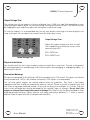
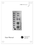
// K4816 // Pattern Generator
User Manual
Hardware Version A / E
Firmware Version 1.0 / 1.2
April 4, 2011
Kilpatrick Audio
// K4816 // Pattern Generator
2p
Introduction
Welcome to the wonderful world of the K4816 Pattern Generator, the Buchla version of the popular
K4815 Pattern Generator for Eurorack. The K4816 is a unique and flexible way of generating notes,
rhythms and modulation voltages or control changes. The user interacts with the machine to set the
patterns using an unconventional method which works well to find new grooves and musical
inspiration. It is a perfect performance tool, a source of notes for jamming, or a way to creating
voltages synchronized to a common clock. This manual will explain the features and operation of the
unit. Please check for updates to the documentation and firmware often as new features may be
added at users' request. We continually strive to advance our products for your benefit and enjoyment.
The K4816 builds on the success of the K4815 but offers a number of new features such as voltage
control of various parameters, an enhanced clock system, the ability to generate MIDI CC and clock
messages from analog voltages, and a built-in MIDI interface.
Features
•
•
•
•
•
•
•
•
•
•
•
•
•
Buchla form-factor with 7” height, 1 space (4.25”) wide
Musical note, control and clock signals generated using unique methods
64 LED (8x8) multi-brightness grid to show patterns and status
Clock control via internal clock, or external MIDI or analog clock
Clock, Direction, Start, Continue and Stop inputs (10V pulses, or 10V held for Direction)
Motion Start, Motion Length, and Pattern Type CV inputs (0-10V range)
Offset Input actively mixes (analog) with CV/X output for transposition or modulation
CV/GATE or X/Y analog outputs (0V to 10V range)
CV is 1.2V/octave – 8 octave range
GATE supports Buchla-style trigger pulse / sustain waveform for controlling 281e, etc.
Built-in MIDI input supports note, CC and clock control over MIDI
Built-in MIDI output to drive synths and sequencers, and use as a CV to MIDI interface
Comes equipped with a Buchla power cable – requires +15V, -15V and +5V for operation
User Manual
Hardware Version A / E
Firmware Version 1.0 / 1.2
April 4, 2011
© 2011 Kilpatrick Audio
// K4816 // Pattern Generator
3p
Installation and Setup
When installing the K4816 in your modular system, make sure that you check and connect the power
cable carefully and correctly. Wrong installation could damage this or other modules. The warranty
does not cover damage caused by wrong installation.
There are internal cables and adaptor boards installed during assembly. Never disconnect or alter the
on-board wiring as this could cause damage to the module.
The K4816 Pattern Generator supports both MIDI and control voltage/gate/clock signals. The built-in
MIDI functions are available on the front-panel MIDI ports. To set the MIDI channel, tap the MIDI learn
button and send a note or CC message within a few seconds. The unit will switch to the new channel.
The learned channel will be stored in internal EEPROM and survives power cycling.
User Manual
Hardware Version A / E
Firmware Version 1.0 / 1.2
April 4, 2011
© 2011 Kilpatrick Audio
// K4816 // Pattern Generator
4p
Output Voltage Trim
The voltage trim on the outputs is factory calibrated into a 100K ohm load. But depending on your
setup you might need to adjust it if the scale tuning is wrong with your oscillators. The multi-turn trim
pot supplied on each output can adjust the tuning over a significant range.
To trim the outputs it is recommended that you set up a pattern consisting of octaves played in the
large scale span. You can adjust the trim pots until the notes play in tune.
Output Voltage Trim:
Adjust the output voltage trim with a small
flat screwdriver to achieve the correct scale
span with your VCO.
R32 = CV/X trim
R33 = GATE/Y trim
Output Voltage Trim
Physical Installation
You should install the unit in your modular system using all four screw holes. The unit is designed to
be mounted properly to avoid damage to the internal parts when plugging or unplugging cables, or
adjusting the controls.
Connection Warnings
All inputs are designed for 0V (off) and +10V (on) or proportional 0-10V control. The inputs are tolerant
of any voltage from -15V to +15V, however using only 0-10V signals is recommended.
The cv/x and gate/y outputs are analog outputs driven by amplifiers. They have a low output
impedance and thus should not be driven by external sources. Please use them as outputs only, and
mix them using proper buffered mixing circuits and not by passive multiples or Y-cords. They are
short-circuit protected but may be damaged by the external input of voltages. Do not short the
outputs or connect them to any other source of voltage! The Offset In jack has been provided to allow
buffered mixing of external signals with the cv/x signal. Internally a buffered 1 + 1 mixer is used to
add the Offset In signal with the cv/x output from the K4816.
User Manual
Hardware Version A / E
Firmware Version 1.0 / 1.2
April 4, 2011
© 2011 Kilpatrick Audio
// K4816 // Pattern Generator
5p
First Use
Connect the CV and gate outputs to a VCO CV input and an envelope generator gate input and let's
make some sound! The K4816 has a built-in clock generator so you can create patterns without any
external clock source. Flip the int/ext switch up to use the internal clock mode. The CLOCK SPEED
control affects the tempo when in internal clock mode. The CLOCK LED pulsates once per beat. Note
that in internal clock mode, the notes operate at 4x the clock rate. (16th notes) In the external mode
this is adjustable, as you will see later. Make sure the cv/gate / x/y switch is up. (cv/gate mode)
Choose a motion type by turning the MOTION TYPE knob. This selects the motion of the playback ball.
Turn up the MOTION LENGTH knob to maximum to play every step in the motion sequence. Adjust the
pattern type with the PATTERN TYPE knob to select where notes will play. You should hear notes being
generated as the playback ball lands on active notes on the grid. Using the maj/min and large/small
switches, you can choose from major or minor tonalities, as well as large and small output spans. The
GATE TIME knob affects how long each note plays, and the MOTION LENGTH knob affects how many
of the up to 64 steps in each motion sequence will play before repeating.
Play around with the controls and hear some of the different possibilities. The next section will cover
each control in more detail, as well as a more overall discussion of how the K4816 makes patterns
based on the settings that you have selected.
User Manual
Hardware Version A / E
Firmware Version 1.0 / 1.2
April 4, 2011
© 2011 Kilpatrick Audio
// K4816 // Pattern Generator
6p
Pattern Generation Concept
The pattern generator concept employed in the K4816 is one that can be thought of as three separate
layers of control. The layers are as follows:
•
•
•
Scale – The scale is the very lowest layer. The notes mapped to each location on the 8x8 grid are
set by the chosen scale. Where in most sequencers the notes are assigned by the user, the K4816
fixes the notes to the grid locations. You can choose either major or minor tonality, as well as
large or small scale span. This may seem like a limitation, but it's not as you will soon see. The
scale mappings are shown below.
Pattern Type – The pattern is set with the PATTERN TYPE control and is shown on the
background of the LED grid at all times. It defines which notes on the grid will play as the
playback ball moves around the display. If a note is lit, it will play. The pattern defines the overall
sound of playback, and can also affect how sparse or dense the pattern is.
Motion Type – The motion is set with the MOTION TYPE control. The motion type defines how the
playback ball will move around the grid during playback. A motion contains up to 64 steps, each of
which can move to any position on the 8x8 grid. If the ball lands on a grid location which is lit by
the pattern, the underlying scale note will play, otherwise the previous note will keep playing.
(depending on the GATE TIME setting) The combination of settings for the motion type and pattern
type offers an incredible array of rhythmic and melodic sequences.
User Manual
Hardware Version A / E
Firmware Version 1.0 / 1.2
April 4, 2011
© 2011 Kilpatrick Audio
// K4816 // Pattern Generator
7p
Advanced Operation
To provide more in-depth detail of the controls and how to make the most of the machine, this section
goes into detail on each aspect of the system.
Internal Clocking and Timing
Using External Clock
The machine uses a 24ppq internal timebase. The clock can be supplied by MIDI timing ticks, by an
analog clock input signal, or by the internal clock generator. The analog clock triggers on the rising
edge and can support clock rates up to approx. 100pps. (250bpm) Each clock pulse input accounts for
1/24th of a beat. When using external clock mode you can adjust how many clock pulses are required
to advance the pattern one step. These are set by the CLOCK SPEED pot and range from 1-24 pulses
per step. The supported divisions allow: 1, 2, 3, 4, 6, 8, 12 or 24 notes per beat. (24 ticks) The division
is only changed at the end of a beat (24 internal counts] to prevent jumpy behaviour.
When external clocks are input either by MIDI or by the analog clock input, MIDI clock pulses are
transmitted on the MIDI OUT port. In this way you can convert analog clock signals to MIDI signals.
Note: Using MIDI and analog clock at the same time may produce undesired results.
To prevent stuck notes in the case of external clock loss, playing notes are automatically killed if no
clock signals are received for 10 seconds.
Using Internal Clock
When using the internal clock mode, the CLOCK SPEED pot sets the tempo. In this mode the pattern
always advances four steps per beat. (16th notes) The tempo generated by the internal clock can
range from approx. 19 to 400bpm. When using the internal clock mode, MIDI clock is automatically
transmitted. If the CLOCK SPEED pot is turned all the way down the clock will be stopped.
Clock LED
The clock LED will pulse for a short time at the beginning of every beat (internal or MIDI clock mode)
or whenever an external clock pulse is received on the clock input jack.
GATE TIME Control
When notes are played, the GATE TIME control affects how long the notes will play. When in the
minimum setting, the note will play for 1 internal clock tick. At the maximum setting, the note can
play for more than two full beats. Note that this control scales automatically with the tempo. Some
synthesizer patches might be barely audible if the gate time is short and the tempo is high.
User Manual
Hardware Version A / E
Firmware Version 1.0 / 1.2
April 4, 2011
© 2011 Kilpatrick Audio
// K4816 // Pattern Generator
8p
Fwd/Rev Control and Dir Input
While any motion is playing, the direction can be reversed by adjusting the fwd/rev switch. It can also
be reversed by an external voltage. If a voltage is placed on the dir input jack, the current direction of
the pattern will be reversed. The direction can also be changed by using the MIDI CC #64. (damper
pedal) When the damper is pressed down, the direction will be reversed.
Reset Control
You can reset the playback position of a motion at any time by pressing on the MOTION TYPE knob. You
can also reset the playback position by inputting a pulse into the start jack. Note that the position is
reset only once each time the knob is pressed or a pulse is received. This works even when the clock
is stopped. The next note to play after resetting when the clock resumes will be the first note in the
pattern. This is similar to the "reset to 16th note" on some sequencers, however in this case the effect
is the same without requiring any special settings.
Output Mode via the CV/Gate / X/Y Switch
Normally the cv/gate / x/y switch is in the cv/gate mode (up). In this mode notes are generated as CV
and gate on the output jacks, and MIDI note messages are sent on the MIDI bus. In the x/y mode
(down), the CV and gate jacks output signals which are related to the absolute playback ball position
on the LED matrix. This can be used for modulation or other uses of varying voltages. The X output
sends the horizontal position and the Y output sends the vertical position. The MIDI output sends
continuous controller (CC) messages for the X and Y positions also. These are shown in the MIDI
Implementation section of the manual. Note that the outputs in X/Y mode are stepped and if you want
continually varying voltages you will need to pass them through a glide processor.
Maj/Min and Large/Small Switches
The underlying notes which are used for playback are selected with the maj/min and large/small
switches. As the melodic and rhythmic patterns are based on a wide variety of patterns and motions,
the underlying notes are kept purposefully simple. The maj/min switch chooses major (up) or minor
(down) scales. The minor scale used is the natural minor. The large/small switch affects how many
octaves are mapped onto the grid. In the small mode (down) there are two octaves. In the large mode
(up) there are four octaves.
In the x/y output mode the large/small control affects the size of the output signal. Either small
(down) or large (up) range of control. Experiment with the outputs on either analog or MIDI to see how
this affects your other equipment. The maj/min switch inverts both the X and Y signals in case you
wish to have an opposite voltage output.
User Manual
Hardware Version A / E
Firmware Version 1.0 / 1.2
April 4, 2011
© 2011 Kilpatrick Audio
// K4816 // Pattern Generator
9p
Major Scale
The major scale spans from C to C without any output offset applied. Notes are mapped from left to
right on each row. Every column has the same notes, but different octaves depending on the setting
on the large/small switch.
Minor Scale
The minor scale spans from C to C without any output offset applied. The natural minor is used.
(flattened third, natural 6th and 7th) Every column has the same notes, but different octaves
depending on the setting on the large/small switch.
Large Span
In the large span mode, four octaves are used. These go from low on the top row, to high in the fourth
row. The scales then repeat on the lower half of the grid.
Small Span
In the small span mode, two octaves are used. The lower octave is on rows 1, 3, 5 and 7. The higher
octave is on rows 2, 4, 6 and 8.
Scale Mapping (All Modes)
C
D
E
F
G
A
B
C
C
D
E
F
G
A
B
C
C
D
E
F
G
A
B
C
C
D
E
F
G
A
B
C
C
D
E
F
G
A
B
C
C
D
E
F
G
A
B
C
C
D
E
F
G
A
B
C
C
D
E
F
G
A
B
C
User Manual
Hardware Version A / E
Firmware Version 1.0 / 1.2
April 4, 2011
© 2011 Kilpatrick Audio
// K4816 // Pattern Generator
10p
OUTPUT OFFSET Control
In cv/gate mode, the OUTPUT OFFSET control affects the transposition of the note outputs on CV and
MIDI. You can shift the notes up or down by semitones. A full 8 octave range is possible.
In x/y mode, the OUTPUT OFFSET control affects the DC offset of the X and Y signals. You can use this
control to get the varying signal into the right range for your equipment. The span of the x/y output is
2.5V to 7.5V, so you can shift this up and down.
PATTERN TYPE Control
The PATTERN TYPE control selects from one of 32 internal patterns which display on the background
of the LED matrix and determine which of the underlying scale notes will play when the playback ball
lands on them. There is a range of geometric and other special patterns to choose from, all of which
provide different kinds of notes and rhythms depending on the motion type used. There is also a
pattern with every note enabled which may be useful for testing and hearing different motion patterns
and scales in their entirety.
User Manual
Hardware Version A / E
Firmware Version 1.0 / 1.2
April 4, 2011
© 2011 Kilpatrick Audio
// K4816 // Pattern Generator
11p
MOTION TYPE Control
The MOTION TYPE control affects how the playback ball moves around on the display. Each motion
type can have up to 64 steps. Each of these steps can land on any position on the grid, and positions
can be visited twice, so quite complex motions are possible, not just sequential patterns. There are 64
motion types which are selected by using the MOTION TYPE control. Pressing on the control resets
the motion playback position to the first step.
When you change motion types, the selected motion is shown on the display briefly in the form of two
intersecting lines. The horizontal line represents the row, and the vertical line represents the motion
number from 1-8 along that row. This allows all 64 motions to be shown by the intersection of two
lines on the grid.
The MOTION TYPE can also be set via MIDI program change. Patches 1-64 select the 64 motions
available from the front panel of the machine. Patches 65-128 select the same patches but in "key
trigger" mode, meaning that the motion will only play when MIDI note messages are received (keys
pressed) on a MIDI keyboard. This allows the machine to work as an auto-arpeggiator.
There are some special motion types which are not pre-programmed, but instead are set randomly.
These allow either continually changing random motions, or random motions which are seeded each
time the motion is selected, so that repetition of the motion is possible.
Preset Motions
Preset motions are available from patches 1-48. These are hand-generated by several collaborators
and contain simple linear motions, as well as more complex motions. Motions are up to 64 steps long,
but some are less than this based on the particular design concept. Some are visually designed and
others are musically designed, taking into account the underlying scale notes to create melodic and
arpeggiating patterns.
Random Motions
In addition to the 48 preset motions, there are also 16 random motion types in locations 49-64. These
are algorithmically created in real-time using a pseudo-random number generator. There are two
random motion types with up to eight variations possible for each. See the list below for the variation
types.
•
•
Seeded Random – All 64 possible steps are seeded with random values once. Subsequent
playback causes the same motion to be repeated.
Totally Random – Each motion step is generated new every time. This creates a constantly
changing random sequence.
User Manual
Hardware Version A / E
Firmware Version 1.0 / 1.2
April 4, 2011
© 2011 Kilpatrick Audio
// K4816 // Pattern Generator
12p
Motion List
1 - Sequential left to right and top to bottom.
2 - Sequential top to bottom and left to right.
3 - Sequential zig zag left/right from top to bottom.
4 - Sequential zig-zag up/down and from left to right.
5 - Jumping from the start.
6 - Crazier jumping from the start.
7 - Spiral
8 - Diagonal zig-zag from bottom left corner.
9 - Skipping zig-zag from bottom right corner.
10 - Up and down triads.
11 - Octave jumping 5ths.
12 - Octave jumping wiggly worm.
13 - Octave jumping rows of four.
14 - Wiggles in different directions.
15 - Preset scatter 1.
16 - Preset scatter 2.
17 - Preset scatter 3.
18 - Ping-pong horizontal mirror reflection.
19 - Cat.
20 - Hanon.
21 - Diagonal zig-zag from bottom right corner.
22 - Diagonal zig-zag ping-pong from bottom right corner.
23 - X circle
24 - Stars.
25 - Ropes and knots.
26 - Squares of different sizes.
27 - Hurricane shape.
28 - C-E-G Triad
29 - D-F-A Triad
30 - C-E-G-B Triad
31 - D-F-A-C Triad
32 - C-E-G-C Triads Up/Down
33 - E-C-C-G Triads
34 - F-D-A Triads
35 - The Sound of Five
36 - Slither
37 - Mini Slither
38 - Mini Slither 2
39 - Crossing Over
40 - Groove 1
41 - Groove 2
42 - Groove 3
43 - Groove 4
44 - Groove 5
45 - Groove 6
46 - Groove 7
47 - Groove 8
48 - Groove 9
49 - Seeded Random - Seconds
50 - Seeded Random - Thirds
51 - Seeded Random - Fifths
52 - Seeded Random - Row 1
53 - Seeded Random - Rows 1 and 2
54 - Seeded Random - 1, 2, 3 and 4
55 - Seeded Random - 1, 2, 5 and 6
56 - Seeded Random - All Notes
57 - Totally Random - Seconds
58 - Totally Random - Thirds
59 - Totally Random - Fifths
60 - Totally Random - Row 1
61 - Totally Random - Rows 1 and 2
62 - Totally Random - 1, 2, 3 and 4
63 - Totally Random - 1, 2, 5 and 6
64 - Totally Random - All Notes
MOTION LENGTH Control
Each motion type can have up to 64 steps. But it can sound interesting to play fewer steps. By turning
down the MOTION LENGTH control you can play from 1-64 of the total steps in the motion. The
motions will repeat once the end of the motion (or the current length setting) is reached.
User Manual
Hardware Version A / E
Firmware Version 1.0 / 1.2
April 4, 2011
© 2011 Kilpatrick Audio
// K4816 // Pattern Generator
13p
Clock Control Inputs
The clock control consists of five inputs. They work as follows:
Clock Input
The clock input is used to provide external clock pulses to drive the pattern generator internal clock.
The CLOCK SPEED control adjusts the input clock divider to one of the following: 1, 2, 3, 4, 6, 8, 12 or
24. Note that the divider setting is only updated after a complete beat (24 pulses) are received. This
prevents jumpy behaviour while the control is being changed.
Dir Input
The dir input reverses the current playback direction selected by the fwd/rev switch. Hold a voltage on
this input to reverse the direction.
Start Input
The start input resets the playback position and starts the clock when a pulse is received. It also
sends a MIDI start clock message.
Continue Input
The continue input starts the clock when a pulse is received. It also sends a MIDI continue clock
message.
Stop Input
The stop input stops the clock when a pulse is received. Analog clock pulses, MIDI clock ticks or
internal clock pulses can still be received or generated, but the playback will be halted until a Start or
Continue pulses (or MIDI message) is received. This also sends a MIDI stop clock message.
Note that if you need to restart the clock and no pulses are available, switching the int/ext switch or
turning the clock speed down and then up again (in internal mode only) will restart the clock.
User Manual
Hardware Version A / E
Firmware Version 1.0 / 1.2
April 4, 2011
© 2011 Kilpatrick Audio
// K4816 // Pattern Generator
14p
CV Inputs
The motion inputs allow the motion start and length to be controlled by voltages.
Motion Start Input
The motion start has no front panel control and defaults to starting at the first position in a motion
sequence. Applying a voltage from 0-10V to the motion start input will offset the starting position of a
sequence from position 1 to 64.
Motion Length Input
The motion length is usually adjusted by the front panel MOTION LENGTH control. A voltage can be
applied to the motion len input to adjust the length. A voltage from 0-10V adjusts the length from 1-64
steps. The voltage will only increase the length from the current value set on the MOTION LENGTH
control. For complete voltage control it is necessary to turn the MOTION LENGTH control all the way
down. Otherwise the input will simply increase the length as it goes beyond the current front-panel
setting.
Pattern Type Input
The Pattern Type input allows the current pattern to be adjusted by a voltage. Similar to the motion
len input, the pattern type input will only increase the pattern type up from the current setting. A
voltage from 0-10V will adjust the pattern type from pattern 1-32. For the full range of voltage control
turn the PATTERN TYPE control all the way down.
Offset Input
The offset in allows the cv/x output from the K4816 to be mixed with an external voltage. An active
buffer circuit is used to mix the two signals together with a 1 + 1 relationship. For instance, if the
pattern generator is making 5V and 5V is input to the offset in jack, the output will be 10V. The mixing
is done in the analog domain so signals can pass through the unit unaltered.
User Manual
Hardware Version A / E
Firmware Version 1.0 / 1.2
April 4, 2011
© 2011 Kilpatrick Audio
// K4816 // Pattern Generator
15p
MIDI Implementation
In addition to analog interfaces available from the front panel, the K4816 fully supports MIDI and
provides a number of useful functions that are not available on the front panel. It also provides a
useful MIDI clock output which can be used as either a stand-alone MIDI clock generator, or as an
analog to MIDI clock converter.
It also provides clock input via MIDI clock, which can be used instead of the analog clock input.
Control change and note outputs are supported, as well as note and controller input for transposing
the pattern, using key trigger playback mode, and reversing the direction of playback.
MIDI Ports
The front panel of the K4816 provides MIDI IN and OUT ports. The MIDI IN jack is used for inputting
clock, note and CC messages for controlling the K4816.
The MIDI OUT jack is used for outputting generated clock, note and CC messages. Some messages
received on the MIDI IN jack will also be relayed on the MIDI OUT jack as long as they are channel
voice controls on the currently set MIDI channel. Notes and some other messages are not echoed.
Also output on the MIDI OUT jack are the motion start, motion len and pattern type input values. A
voltage range of 0-10V produces CC values from 0-127.
MIDI Clock Support
By sending MIDI clock to the machine while it is in external clock mode, it is possible to synchronize
the machine to an external MIDI sequencer or other clock source. The input is divided by the CLOCK
SPEED control just as with an analog clock input.
When running in any clock mode, MIDI clock is sent to the MIDI output. This means that the machine
can be used as a MIDI clock generator (internal clock), or an analog to MIDI clock converter.
MIDI clock start, continue and stop messages are also both sent and received and can be used to
control the playback of the pattern generator from a computer or drum machine.
MIDI Program Change
The 64 motion types can be selected by a MIDI program change command received by the machine.
Programs 1-64 correspond to the 64 patterns selectable by the MOTION TYPE control. Programs 65128 correspond to the same 64 patterns, except that keyboard trigger mode is enabled. Keyboard
trigger mode allows the playback of a motion to be started when a key is pressed, to use the K4816 as
a sort of auto-arpeggiator.
User Manual
Hardware Version A / E
Firmware Version 1.0 / 1.2
April 4, 2011
© 2011 Kilpatrick Audio
// K4816 // Pattern Generator
16p
MIDI Note Support
When in cv/gate output mode, MIDI notes corresponding to the ones being sent from the CV and gate
outputs will be sent. The note length and transposition are the same as the analog outputs.
Notes received by the machine from an external MIDI keyboard will transpose the currently playing
notes. Middle C is treated as the default transposition. Any notes higher or lower will shift the note
playback by the corresponding number of semitones away from middle C.
When one of the patches from 65-128 is selected, notes received by the K4816 will trigger the start of
playback at the beginning of the motion sequence. If you play legato, the notes will be transposed, but
the motion will continue playing through to the end before repeating. If you play staccato, the motion
will restart from the beginning for each note.
MIDI Controller Change
While in x/y output mode, instead of transmitting MIDI notes, continuous controller messages will be
sent. Controllers 16 and 17 correspond to the X and Y values of the playback ball respectively. The
large/small switch affects the size of the output, and the maj/min affects the polarity of the output
voltages.
When MIDI controller 64 (damper pedal) is received the current playback direction is reversed just as
with the analog dir input.
MIDI CC messages are generated based on the motion start, motion len and pattern type inputs. The
mapping is as follows:
• pattern type – CC 20
• motion start – CC 21
• motion len – CC 22
Note that the CCs sent are just the sampled value from the input jacks and do not represent the current
position of the internal pattern generator state for these functions. You can also send these CC values to
the K4816 MIDI IN to adjust these settings as if they were being adjusted by a CV input.
MIDI SYSEX Messages
A series of SYSEX messages are used for software updating and loading new motions, patterns and
scales. Currently this requires software from Kilpatrick Audio and will be sent to owners of the K4816
who request additional or different features or require bug fixes. Please contact Kilpatrick Audio for
more information if you would like to experiment with this feature.
User Manual
Hardware Version A / E
Firmware Version 1.0 / 1.2
April 4, 2011
© 2011 Kilpatrick Audio
// K4816 // Pattern Generator
17p
Support and Additional Information
Please contact Kilpatrick Audio with additional questions about the K4816 Pattern Generator. We will
do our best to help you make the most of your product and welcome your suggestions as to software
improvements or ideas for features on new products. Contact: [email protected]
User Manual
Hardware Version A / E
Firmware Version 1.0 / 1.2
April 4, 2011
© 2011 Kilpatrick Audio
// K4816 // Pattern Generator
K4816 Pattern Generator
Function
MIDI IMPLEMENTATION CHART ver.1.1
18p
2011-04-04
Transmitted
Recognized
Remarks
1 (default)
1-16 (configured)
1 (default)
1-16 (configured)
Use TEST mode to set
the MIDI RX channel.
X
X
X
X
X
X
0-127
0-127
O
X
Sent at value 100
O
O
O
O
Echoed from input
Pitch Bend
O
O
Echoed from input
Control Change
O
O
Channel mode messages
are not echoed
16 = X output
17 = Y output
20 = Pattern Type CV
21 = Motion Start CV
22 = Motion Length CV
20 = Pattern Type
21 = Motion Start
22 = Motion Length
64 = Dir input
Prog
Change True #
X
0-127
0-63 / 0-63
Upper bank has "key
trigger" enabled.
System Exclusive
O
O
For testing and firmware
update only
System
Common
Song Position
Song Select
Tune Request
O
X
X
O
X
X
System
Realtime
Clock
Commands
O
O
O
X
Aux
Messages
Local On/Off
All Notes Off
Active Sensing
System Reset
X
X
X
X
X
X
X
X
Basic
Default
Channel Changed
Mode
Default
Messages
Altered
Note Number
Velocity
After
Touch
Keys
Ch's
MIDI clock timeout is 10 seconds.
Notes
Software update specification available upon request. Implemented by Kilpatrick
Audio update software as supplied to customers.
User Manual
Hardware Version A / E
Firmware Version 1.0 / 1.2
April 4, 2011
© 2011 Kilpatrick Audio