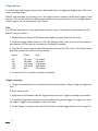
1
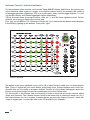
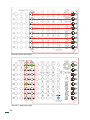
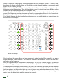
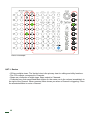
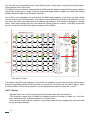
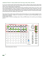
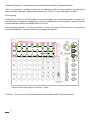
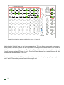
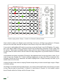
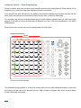
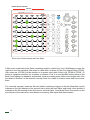
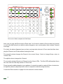
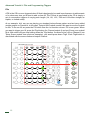
CIRCADIAN RHYTHMS
User Manual
Circadian Rhythms
for modular music composers
INDEX
Introduction ......................................
p.02
Section 1
Quick Start Tutorials ............................p.03
1 - Vertical View Basics .....................p.03
2 - Other Views .................................p.07
3 - Groups and Presets Plus Copy,
Paste and Save ............................p.09
4 - Looping Presets and Groups for
More Complex Patterns ...............p.11
Advanced Tutorials ..............................p.13
1 - Zoom Programming .....................p.17
2 - Fills and Programming Triggers ...p.20
3 - Programming Gates .....................p.22
4 - Syncing to Your DAW .................. p.24
CR Tips and Programming Ideas ....... p.31
Section 2
Functions in Detail ...............................p.32
Views .....................................................p.33
- Vertical View
- 8x8 View
- 4x16 View
- 2x32 View
- 1x64 View
- Zoom View
Clock In .................................................p.37
SyncBus and Channel Expansion ......p.38
Swing .................................................... p.39
Looping ................................................ p.40
Preset Loops
Group Loops
Editing While Looping
Programming Triggers and Gates ......... p.41
Channel Step Editing .............................. p.41
Trigger Buttons ........................................ p.42
Fills
Trigger Recording
Startup and Utility Functions ................. p.43
Updating Firmware
Clearing Internal Memory
Checking Firmware Version
Specifications .......................................... p.44
Credits ...................................................... p.44
Circadian Rhythms Features
Hardware:
• 8 trigger/gate outputs
• Highly Accurate Internal Clock and Reset output
• External Clock and Reset input
Rhythmic Functions:
• Up to 512 step sequences - 8x8x8 storage in memory
• 16th note main grid resolution
• 24ppq resolution in Zoom view for deep-dive, detailed sequence editing
• Trigger delay per step
• Swing with 8th or 16th notes
• Gate width outputs gates up to 64 steps long
Introduction
Thank you for purchasing the Circadian Rhythms. The CR (as we’ll refer to it henceforth) is a unique rhythm sequencer for the Eurorack format that takes the original idea behind the XOX step sequencer and transforms it into a more flexible performance tool that encourages improvisation and
experimentation.
We recommend placing the CR in front of your modular in a desktop rack, like the Happy Ending Kit
or other skiff case, for easy access to the buttons. The CR was designed to be the master controller
of your modular: it will supply clock and reset signals for sync to all other sequencers, clock dividers
and such in your system, trigger the envelopes of your patched synth sounds and all your drum
sounds. The CR gives you eight sequencer channels for multi-voice musical composition entirely
on the modular. Additional channels can be added with additional CRs and/or Trigger Riots using
Tiptop SyncBus connectors located at the back of the module which keeps them all in perfect sync
as if they were one big sequencer.
This manual has two sections:
1) Quickstart and Advanced tutorials for step by step instructions on a specific task. These examples
will give you enough knowledge of the CR’s structure and functionality to start using it.
2) Detailed function descriptions that form the Reference part of the document including Specifications.
Just FYI before we get started:
• In this manual, “Columns” refer to vertical lines of buttons. “Rows” refer to horizontal lines. The
CR has nine columns and eight rows.
• Terms that refer to labels on the CR are capitalized.
• NxN View to a concept or action that is applicable to any of the horizontal grid views: 1x64,
2x32, 4x16, 8x8.
02
Quickstart Tutorial 1: Vertical View Basics
For the purposes of this exercise, we’ll use the Tiptop 808 BD, Hihats, and Snares, but you can use
any module that takes a gate or a trigger for an input to make a sound (for example, this could be
an envelope generator triggering a VCA or a lo pass gate). Now, connect trigger outputs 1, 2, and
3 to the BD, Hihats, and Snares trigger/gate inputs respectively.
CR has five main views (from top to bottom: 1x64, etc…), all in the lower righthand corner. For the
moment, we’re going to explore the vertical view.
First, let’s set our BPM to 120. Rotate the Clock knob. You’ll notice that the button matrix displays
in the BPM by lighting up the buttons. Pretty slick, right?
+
-
v
v
CLOCK 120 BPM
The button in the lower righthand corner of the CR is called Vertical: make sure it is illuminated in
Blue. Think of Vertical as your home button and primary view. Vertical displays most of the functionality that you’ll be using to program rhythms. Further, all of the labels that appear above the
buttons in the primary eight columns are meaningful only in the Vertical view.
For this tutorial, in the Vertical view, we’re going to focus on the third and fourth columns called
Steps and Channels. The Channel column refers to the button that is selected in each row. So, if
the channel button for row 1 is green, it means that we are currently viewing Channel 1 which will
output to trigger/gate 1 on the right side of the CR (the BD in our example).
03
v
v
v
v
Channel column and output
Channel 1, steps and output
04
Steps is where you can program your triggers/gates that will generate a rhythm. In Vertical view,
the Steps will appear vertically. Steps are a collection of eight steps. It’s always a collection of eight
steps, not six or three, just eight.
Ok, so we’re viewing Channel 1’s first set of Steps. Let’s fill in some beats. Press the first and the
fifth button on the Steps column. They will illuminate in green. You should now hear a BD kick on the
one and the five making the familiar four-on-the-floor kick.
Let’s add another Channel. Select Channel 2 (the second button in the Channel column will now be
green). The Steps are now blank because we haven’t programmed any Steps for this Channel yet.
In fact, if you selected Channel 1 again, you’ll see the 1 and the 5 in green.
For Channel 2, press the third and the seventh buttons on the column which will output triggers to
the HiHats in our example
v
v
HiHats out example
Finally, let’s add the snare. Since we have connected a cable from the CR’s output 3 to our snare
trigger/gate input, select Channel 3. The Steps for Channel 3 are blank now. Press in the fifth column button on the Snare row.
Now you’ve got the classic house/techno rhythm pattern. If you press Channel 2 again, you can see
your selected triggers for your hihats coming from CR’s output 2; likewise for the BD for Channel 1.
The Mute button immediately in the column to the right of a Channel is associated with that Channel
(e.g., the Channel in row 3 is associated with the Mute button in row 3). When the Channel is actively
generating steps, the Mute button lights up green to let you know when that channel is firing. Press
the Mute button for the Channel you wish to mute. The muted Channel will no longer fire triggers/
gates. Press the Mute button again to unmute the channel.
05
v
v
Snare out example
QST 1: Review
• CR has multiple views. The Vertical view is the primary view for editing and utility functions.
• The CR’s outputs correspond to Channels.
• Steps are a collection of eight steps. Steps output to Channels.
• Channels have their associated Mute button on the same row in the column immediately to
the right of the Channel. When unmuted, Mute shows you when a Channel is triggering. Press
the associated Mute to mute a Channel.
06
Quickstart Tutorial 2: Other Views
Don’t reset the classic house/techno rhythm pattern we programmed in the previous tutorial.
Let’s explore the other four views besides Vertical. As stated earlier, Vertical is the primary view for
programming rhythms. However, the CR’s views can be used in performance to program and/or
view your Steps on the fly.
For example, let’s select 8x8, the button right above Vertical. Switching to this view, you’ll notice
immediately that the lights switch from moving vertically to horizontally. the 8x8 view displays all
the current Steps for each of the eight Channels all outputting triggers/gates to their corresponding
numbered outputs on the right.
Your 8x8 should look like this:
BD
HIHATS
SNARE
8x8 View of Pattern
07
You can edit your step patterns here in the 8x8 view also. Some users may prefer to start programming rhythms here in this view.
The other three non-Vertical views besides the 8x8 view are similar except that they show patterns
larger than eight steps in length. Patterns larger than eight steps in length are created by looping
presets which will explore in Quickstart Tutorial 4.
Just to fill in our knowledge, let’s look at how the 2x32 View appears. In this view, you have visible
access to two rows of 32 steps each. The views of each Channel break down by this division, so you
can see 2 channels of 32 step patterns simultaneously (likewise, 4x16 shows 4 channels of 16 steps
each). This means that the top four rows show the 32 step output to channel 1 (the BD) and the the
top four rows show the 32 step output to channel 2 (the HiHat).
BD
HIHATS
2x32 View of Pattern
If we want to see the other channels, in the 2x32, we navigate up and down using the up and down
buttons immediately below the Zoom button. If you want to see channel 3 (the snare output), press
the down button. Press the up button to see the programmed steps for channels 1 and 2.
QST 2: Review
• Multiple views let us view step programs at the same time and edit on the fly.
• The formula for each view is number of viewable channels x number of steps, e.g., 4x16 means 4 simultaneously viewable channels of 16 steps each.
• We can view other channel outputs in views larger than 8x8 by navigating up and down with
the up and down buttons.
08
Quickstart Tutorial 3: Groups and Presets Plus Copy, Paste, Clear, and Save
So far, we’ve made a pretty simple rhythmic pattern, seen it in different views in the CR, and had the
opportunity to edit in those views. Now, we’re going dive into groups and presets which will pave the
way for more complex pattern programming.
Let’s select the Vertical view we still have the basic house/techno beat running, let’s clear it and
start something different. To clear, a Channel (or Groups and Presets as we’ll see shortly), press the
Clear button in Vertical view. Nothing happens until you press the Channel you want to clear. In this
case, press the Channel 1 button. Now your kick drum should be cleared. To clear the other sounds,
press Clear and then the Channel you wish to clear.
Now, we’ll create a pattern and a variation to demonstrate. Keep your same outputs plugged into the
CR with BD on Channel 1, HiHat on 2, and Snare on 3. A Preset is a set of 8 Channels and a set of
Steps for each Channel.
For this pattern, let’s pick something slower. Dial your BPM down to 90 and Set up the following
pattern:
Slowed down pattern. 8x8 view.
09
You should have this pattern in Preset 1 which is the first button in Vertical under the Preset column.
Now, press the button for Preset 2 below Preset 1. You should hear no sound being output. This preset is empty because you haven’t filled in this preset. Press the button for Preset 1 and you should
hear your original pattern.
We’re going copy the pattern for Preset 1 and paste it into Preset 2. Copy and Paste work similarly
to Clear: First you press the action button and then where you want it to happen. In this case, press
Copy and the Copy button will turn red, then press Preset 1 and copy will turn green. Green means
there is data in the buffer that can be copied. Now, press Paste and Press Preset 2. Your pattern
for Preset 1 should now be copied and pasted into Preset 2. You can test this by pressing back and
forth between Presets 1 and 2.
COPY
PRESET 1
PASTE
PRESET 2
C.R. MEMORY
COPY, THEN SELECT PRESET 1
PASTE, THEN SELECT PRESET 2
Copy and paste procedure.
The principle of copy and paste works for Channels also. If you want to copy a set of Steps into
another Channel out, press Copy and the Copy button will turn red, then press for example Channel
2. Now, press Paste and Press Channel 4.
Practice copying and paste from Presets 1 and 2 and into other Presets. Create variations in your
rhythmic patterns in different presets.
10
Looping Presets and Groups for More Complex Patterns
Let’s explore Groups. Groups are structurally similar to Presets except that Groups contain 8 Presets. Right now, we should be in Group 1. If you Press Group 2 (one button down from Group 1 in
the Group column), Group 2 will illuminate and you will hear no sound. Group 2 is empty.
You can copy and paste among Groups in the same manner and you copied and pasted Presets.
Press Copy and the Copy button will turn red, then press Group 1 and copy will turn green. Green means there is data in the buffer that can be copied. Now, press Paste and Press Group 2.
Your presets (of Channels and Steps) for Group 1 should now be copied and pasted into Group 2.
Press and hold down the Start/Stop button to the left of Vertical. This stops the CR clock and simultaneously saves all of your Groups, Presets, and Channels of Steps. Press Start/Stop to start the
CR clock running again.
QST 3: Review
• Groups and Presets are containers of eight that serve as organizational blocks for your rhythmic patterns of Steps. A Group contains eight Presets. A Preset contains eight Channels of
Steps.
• Copy, paste, and clear all work on Groups, Presets, and Channels of Steps. To use them, you
press the action button and then where you want it to happen.
• Start/Stop stops and starts the CR’s clock. Holding it down also saves to non-volatile memory
the data (so the saved settings loads on next power up) in all your Groups, Presets, and Channels of Steps.
11
An Aside: The Ladder of Being
The Ladder of Being is an old concept used to describe a hierarchical set of containers that fit inside one another. The CR’s groupings are structured like the Ladder of Being. For more info: http://
en.wikipedia.org/wiki/Great_chain_of_being
Going down the ladder:
A Group has eight Presets. A Preset has eight sets of Steps and Channels. A set eight Channels has
eight Steps each.
Up the ladder. Channels and Steps are intimately tied together. Each Channel has eight Steps. Each
Preset has eight set of Channels and Steps. Each Group has eight set of Presets that belong to it.
This is the order of the CR universe.
CR’s Ladder of Being.
12
Quickstart Tutorial 4: Looping Presets and Groups for More Complex Patterns
“Yes,” you are saying, “groups and presets are interesting and all, but our patterns are still only 8
steps in length. How can I make patterns that are 16, 32, 64, or even 256 steps in length?”
Enter looping.
Looping as a function in the CR allows you to loop through a set of selected presets or groups. You
can also think of looping as combining (or really concatenating) a set of presents or groups, but that
would make the concept less flexible than it is truly is.
Let’s create an example... Let’s choose Group 1, Preset 1 in Vertical View and enter in our standard
house/technopattern. Switch to 8x8 view to program the pattern:
Simple House/Techno pattern for Group 1, Preset 1.
In Group 1, Preset 2, let’s add a little variation to the HiHat and BD. Enter this pattern:
13
Simple House/Techno pattern variation for Group 1, Preset 2
Switch back to Vertical View for the Loop programming. To Loop these two presets and create a
longer pattern, we need to press the Set Loop button. Looking at the Presets column, this shows us
which presets are currently part of our Preset loop. By default, all of the Presets will be activated.
For our loop, we only want Presets 1 and 2. Press the Preset buttons for Presets 3 through 8. This
will deactivate all the presets in the loop.
Now, press Preset Loop On/Off. Your two Preset loop should now be playing, cycling through Presets 1 and 2. The currently active Preset in the loop is red.
14
Preset Looping active: Group 1, Preset 2 for Channel 3 (Snare) shown.
Here’s what is really cool: Switch to the 4x16 View. You have a 16 Step Loop pattern of 2 Presets
and you can now view and edit the Steps in this View (or any of the other nXn Views).
If you want to add additional Presets to your loop, press the Preset Loop On/Off button. For example, if you want to add Preset 3, press the Preset Loop On/Off button and press Preset 3 and it will
turn green. This preset is probably empty (unless you have been filling up your preset banks), so
we can select the 2x32 view to edit our entire 24 Step Loop pattern (or just edit Preset 3 in Vertical
view).
Just because we chose consecutive Presets for this example doesn’t mean you have to also. If you
want to loop, say, Presets 2,6,7, there’s nothing stopping you as far as the CR is concerned. Your
selected Presets will all be treated as the same looping block of Steps internally and also if you
switch views to a nXn view.
Looping Groups is the same as looping Presets except that you have a much larger range of Steps
to choose among.
One thing to remember about looping Groups: you need to select the Presets in the Group you want
to loop. Say we want to loop Group 1, Presets 1,3, and Group 2, Presets 1,2. You’ll need to select
those Presets within the Group and the Groups to loop.
15
From our Presets example, copy Group 1 to Group 2. For Presets 1 and 2 in Group 2, add an additional Snare hit and add some variations to your HiHat pattern.
To Loop Groups 1 and 2 and Presets 1 and 2 from each Group, we need to press the Set Loop
button and the Group Loop On/Off. Looking at the Groups column, this shows us which Groups are
currently part of our Group loop. By default, all of the Groups will be activated.
Your two Group loop should now be playing, cycling through all the Groups. The currently active
Group in the loop is red. For our loop, we only want to loop Groups 1 and 2, so deactivate the others.
That’s it. You just looped some Groups. Step away. Pour yourself a beer. Let the compositional and
improvisational possibilities sink in. Also, consult page 40 of the document for further details on
Looping.
QST 4: Review
• Loops are the way to create step sequences longer than 8 steps. You can loop either Presets
or Groups.
• To loop Presets, activate Set Loop and Preset Loop On/Off. Select which presets you wish to
loop in the Preset column
• Looping Groups operates on the same principles as looping Presets, but with two differences:
you activate Group looping with Group Loop On/Off and you must select which Presets in the
Group you wish to loop.
16
Advanced Tutorial 1: Zoom Programming
Zoom is another view, but one with a very specific and micro-focused purpose: Zoom allows you to
program your currently 8-step Step sequence at micro resolution.
If we enter Zoom view, we can see our pattern, but instead of having only 8 steps, we have 48; the
extra steps are between the standard 8 steps and we refer to them as Sub-Steps.
For example, say we have a HiHat pattern and we want a pattern denser than our 16th note 8 step
pattern or we want to have sub-steps that fall between our strict 16th note quantization. Let’s edit a
HiHat pattern.
Enter Zoom view and we can see our HiHat pattern look like this:
PRIMARY HITHATS TRIGGERS
SUB STEP
Zoom view: HiHats example.
The standard 8 step pattern is on the first column and you can add additional between notes with
the buttons on the right of the leftmost column. Add a couple of triggers after some of the 8 Steps
to hear what they sound like.
17
PRIMARY HITHATS TRIGGERS
SUB STEP
Zoom view: HiHats example with Sub Steps.
A little music math behind the Zoom resolution might be useful here: the 6 SubSteps increase the
resolution from the standard 16th notes to a 96th note. In terms of Parts Per Quarter Note (PPQN),
16th notes are 4 PPQN (1⁄4 the duration of a quarter note) while Zoom is 24 PPQN (4 PPQN * 6)
which is a popular resolution for a number of reasons. First, it is used by MIDI as the timing of the
Beat Clock making it a standard, and second, it makes creating many useful note lengths easy. See
the details in Section 2 of the manual covering Zoom for a chart of common notes and how to enter
them.
For a musical example, create an 8th note triplet by entering a trigger on the first Step then count 8
substeps to the 3rd substep on the second row to enter the next triplet, and finally count another 8
substeps to the 5th substep on the third row for the final triplet. Consult the Zoom View section in the
second part of the manual for more details on entering other triplet and dotted values.
18
Zoom view: HiHats example with Sub Steps.
Note, you can only edit Zoom steps in Zoom view. You’ll need to switch to Zoom mode from Vertical
or one of the NxN views if you want to make changes to your current pattern that contains Zoomed
sub-steps.
For clarity, the above diagrams leave out two very important columns in Zoom view that allow changing the Channel and Preset without leaving the view:
The seventh column changes the Preset in the current Group. Note: to change Group, return to
Vertical View.
The eighth column changes the Channel.
The currently selected Preset and Channel are the Green LEDs. The Red LEDs differentiate these
two rows from the Sub Step section of Zoom view.
Zoom is great for adding density to your patterns. It can also be used to create off-kilter or broken-beat rhythmic patterns (especially when used in conjunction with the swing function).
Consult the Zoom section on page 36 of the manual for further details
19
Advanced Tutorial 2: Fills and Programming Triggers
Fills
A Fill in the CR is a user-triggered drum fill that is designed to be used in performance to add accents
or for whenever else you’d want to add a drum fill. The Fill that is generated in the CR is simply a
set of consecutive triggers of varying note length (1/4, 1/8, 1/16, 1/32 and 1/64 either straight, as
triplets, or dotted notes).
As an example, let’s say we are playing our standard techno/house pattern and we have added
another output on Channel 4, in this case, Tiptop’s 808 Cowbell module. We want to use the Cowbell
for fills. To fire our fill, we press the Fill button from the 1st function column. Fill is now green. When
you want to trigger your fill, press the Trig4 button (for Channel output 4) and you’ll hear your cowbell
fill at 16th notes until you stop holding down the Trig4 button. If wanted to fire a fill on Channel 3 (our
Tiptop Snare module from previous examples), you would press down Trig3. Each Trig# button is
associated with the same numbered output Channel.
d
20
Please note your fills are NOT recorded in your Step sequences. Fills are designed for live performance.
Let’s have some fun and have a fill with 1/32 triplets. Press the Fill button again to select options for
your fill. The Preset column has divisions from top to bottom of triplet notes of 1/4, 1/8, 1/16, 1/32
duration. Select the 4th button down. Now, press Fill twice to return to an active Fill. Press down the
Trig4 button to fire your fill with 1/32 triplets.
(For further information on programming fills of different note values, see the section on Fills in the
Circadian Rhythm Functions in Detail) section.
Triggers
Simply put, triggers allow you to record steps to your patterns live and on the fly. Some folks feel
more comfortable with this approach to building up rhythmic patterns or sometimes when you have a
good pattern going, it’s great to be able to add beats in real-time. Regardless, CR has you covered.
To activate Trigger programming, hold down the Fill button. The Fill button will turn green and the
Trig1-Trig8 buttons will turn red. The red Trig buttons indicate that they are armed for recording.
While the CR is playing, to record a step in your current Preset, press the Trig for the Channel you
wish to record a step. For example, if you want to record a step on Channel 5, press Trig5. Your step
will be record in the appropriate Channel’s Preset quantized to the nearest 16th note.
Apart from inputting Steps in realtime, there’s nothing special about Steps that have been recorded
using the Trigger function. You can edit them the same as you would for any other Step.
21
Advanced Tutorial 3: Programming Gates
The CR doesn’t generate only triggers. It can also generate gates in Patterns.
As a review, triggers and gates are both “on-off” voltage signals used to activate another module (for
example, to start an envelope generator, advance a clock, or fire a Tiptop BD808). The main difference between the two is the length of each and how they are used. A trigger is typically a standard,
short duration (5ms) signal and is used trigger (hence the name!) a drum module, ping a LPG, or advance a clock. A gate is the same signal as a trigger only the duration of the signal is variable. A gate
is used to activate modules such as an envelope generator where the duration of the output varies.
As an example, let’s set gate in a pattern in Vertical mode for the first five beats of an 8 beat Pattern.
In this case, instead of connecting the Output to a drum trigger input, connect it to an envelope generator such as the the Tiptop Z4000. Connect the envelope generator to a VCA so that the envelope
is activating the VCA, set the Sustain knob on the Z4000 to maximum. Plug in a oscillator (such as
the Tiptop Z3000) to the VCA input to have a sound source.
To activate the gate in the CR for example, hold down the first button Step in the Pattern and the fifth
button Step in the pattern until the first buttons turn to red. That’s it! There’s your gate! To change
the length of the gate to seven Steps, you hold down the seventh Step and the intermediary steps
will be activated (Step 6 and 7). To deactivate the gate, either hold down the first and the last step
in your gate until the buttons are no longer red or press each button in the gate pattern individually.
Pressing Step in an active gate also allows you to edit your activated gate to create multiple gates
in a Pattern.
22
d
d
Gate Example in Vertical View
Gates can run or be created in any view, not only Vertical as in our example. Gates can be looped
and manipulated (for example, copied and pasted) just like triggers.
23
Advanced Tutorial 4: Syncing the Circadian Rhythm to Your DAW (or Any Clock)
Because a true standard for synchronization has never been established, multiple methods for
analog and digital clock synchronization have been developed for different electronic music devices
and their manufacturers. We are hopeful this section can resolve some of the confusion that has
emerged over the years due to the absence of standardization. Below we will cover both theory and
application of sync as it applies generally to DAWs and other electronic music hardware. This is a
potentially confusing topic with many variables so please read carefully and have patience when
setting things up!
In most recording studios, the advent of digital audio workstations (DAWs) such as Apple Logic,
Ableton Live, Pro Tools and Cuckoos Reaper have replaced most analog recording methods. Now,
the DAW is the centerpiece of control and the primary clock in the digital studio, so it makes sense
to understand how to sync the CR to it.
In the digital audio realm, the audio sample is the basic building block and the standard unit by which
all digital audio is measured today. The clock which drives audio interfaces (and thus DAWs) is the
most accurate available to most people and also the best source for common synchronization of
devices.
The clock inputs and outputs of the CR use analog voltage pulses where the rising edge of the pulse
indicates the time to execute the next event. A DAW can generate and record these pulses just like
audio. No additional software or hardware is needed to do this.
Here’s the important concept to grasp: the DAW can treat clock control pulses just like any other
audio signal. Unlike MIDI (which runs separate timing), audio clock pulses are locked to the same
precise clock as the rest of the audio generated by your DAW. To give you an idea of how fine grained control of timing digital audio can be, the CR can be triggered by a single clock a pulse at any
specific sample in your DAW’s timeline.
Further, the DAW can also record the clock pulses from the CR and these recorded clocks can
trigger the CR for sync between subsequent overdubs. This method is probably the easiest and
most modular-centric sync between the DAW and Eurorack hardware. You can now focus on the
the tactile performance of the modular and use the DAW as a fancy tape recorder where everything
runs in sync.
In addition to recording audio pulses from the CR, third party plugins exist for generating a sync
pulse from the DAW to the CR (we use Expert Sleepers’ Silent Way as an example below). If your
tastes run more to the algorithmic side of composition Audio programming environments like Max/
MSP, Pd, or SuperCollider can produce proper sync pulses as well, although the use of these runs
outside of the scope of this manual.
24
Before starting the application section, a few technical notes:
• The rising edge of the pulse triggers the clock. Many audio interfaces have AC coupling which
may invert the rising edge of the pulse. The clock input of the CR is designed with this in mind,
so AC-coupled audio interfaces should work fine with the CR. Align the beginning of the pulse
to the sample or bar/beat to advance the CR’s clock.
• In order to trigger reliably, the level of the pulse signal from your DAW may need to exceed a
few volts. The peak will likely be close to or at 0 dBFS in your DAW. Don’t worry about the signal
clipping; the signal is already a square wave.
• An oscilloscope comes in handy for diagnosing problems with sync pulses. A dual input model
allows the monitoring of latency between input and output as well.
• The musical note for 24 PPQN is a 1/96th note or 1/64th note triplet. Setting the DAW Timeline
resolution to one of these will help in aligning sync.
25
Applications
Expert Sleepers Silent Way
Expert Sleepers have a set of VST/AU plugins called ‘Silent Way’ which provide a range of utility
functions from CV pitch control to Envelope and LFO generation to Synchronization. In this section,
a standard audio interface will be used for signals and not the hardware made by Expert Sleepers
for Eurorack.
After you have Silent Way installed, load an instance of the SW Sync in a channel in your DAW. For
our example, we will say that we are using channel 1 on our audio interface to output the Clock Sync
signal. Set SW Sync ‘Clck Output’ to output to channel 1. Connect the analog output of Channel 1
of the audio interface to the Clock In input on the CR (a 1⁄4” to mini adapter is likely needed). Also,
connect channel 2 to Reset In on the CR and set the ‘Run Output’ to Channel 2. Use the most appropriate channels for your audio interface if 1 and 2 are not available.
To activate an external clock as the clock source on the CR, in Vertical mode, press CLK IN/EXT.
CLK IN/EXT should turn red (when this button is green, the CR is using its own internal clock).
Now, we have two options for sync from our DAW, either 16th note sync or DAW sync. Both are reliable, but DAW mode has a higher level of timing fidelity (because the sync signal is triggering more
frequently). To set up 16th Note sync using SW Sync, simply set the PPQN value to 4 as shown
below. (PPQN is pulses per quarter note. 4 pulses per quarter note x 4 for a four beat measure =
16th notes).
Silent Way Sync Set for 16th Note Sync
26
To set up DAW sync using SW Sync, simply set the PPQN value to 24 as shown below. (24 pulses
per quarter note x 4 for a four beat measure = 96th notes).
Silent Way Sync Set for DAW Sync
One last step: set the right sync on the CR. In Vertical mode, hold down the Global button until the
normal Vertical mode disappears. This is Global mode. In the upper righthand corner, you should select the sync mode that you set up in SW Sync. If you went with 16th note sync, select 16TH. If you
chose DAW mode, press the DAW button to activate it. Press the Vertical button to exit Global mode.
Start the timeline or clock of your DAW (usually this means pressing the Play transport button). If
your connections working properly, you now have rock solid sync!
Reset can be set many different ways based on the needs of the session. When set to ‘Run’ in Silent
Way, the output will remain high until playback is stopped. Change the ‘Run Type’ to ‘Start’ and the
‘Beats’ setting then sends out Reset pulses based on the ‘Divisor’ instead of the static Run signal.
To send a reset every 4 bars, set the ‘Beats’ to 16 and ‘Divisor’ to 1/4 (16 beats / 4 beats per bar =
4 bars).
27
Audio Loop Sync
You don’t need a special plugin to sync the CR to your DAW. In fact, the CR will just as easily sync
to an audio loop of a sync clock. Tiptop has provided some source clock audio files at various BPMs
on the Tiptop Audio website.
To use the audio sync file, simply follow the directions above for using SW Sync, but substitute the
audio sync file. Loop the file in your DAW for the duration of your project and you’ve got one channel
of clock throughout your session.
These files are simply example templates to demonstrate the technique. Making your own audio
sync files is just a matter of placing the clock and reset pulses at the correct locations in the DAW
timeline.
NB: You’ll need an audio sync file that was generated at your desired BPM. Most DAWs include
time-stretching algorithms to alter the length of audio files to match a sequence’s BPM. However, in
our experiments, we have found audio loop files altered using time-stretching algorithms to match
specific BPMs offer inconsistent levels of sync accuracy. We recommend using an audio loop sync
file created at the BPM you desire.
This method also works in reverse: record the Clock and Reset outputs of the CR into the DAW as
the sync track for all additional overdubs.
A Note About Latency and Sync:
All digital devices have to delay the signal in order to sample and work efficiently, this is commonly
called ‘latency’ because it is often a hidden value. The DAW software, USB/Firewire interface, ADC/
DAC chips all have buffers in place for processing and they need to be measured. When setting up
sync with devices outside the computer the round trip delay needs to be compensated for, and often
the setting only works properly when manually set.
The first step is to measure the round trip delay from the DAW, through the audio interface and back
into the DAW timeline. Send a clock signal from Silent Way or use the audio sync pulse method and
record the output onto a separate audio track via the analog inputs and outputs of the interface (just
like it is hooked up to the CR). In the timeline, measure the time between the clock pulse being sent
out and where the recorded one in samples.
Once the delay is measured it can be entered into the settings of the DAW. The following example
uses Ableton Live, but this manual cannot cover every recording application, so please consult the
DAW documentation for how to enter the same settings.
28
The above image shows an audio pulse in the Ableton Clip window sent by Silent Way through the
audio output and recorded back into a track in Ableton. Notice the silence at the start of the region,
this is the delay Ableton has not automatically compensated internally. Measuring the exact number
of samples of silence is the best method for compensation. Unfortunately, Ableton lacks the ability
to use samples as a unit, so this clip was sent to an external editor (Adobe Audition) to measure. In
this case, the number of samples measured 446.
The following image shows the Ableton Live Preferences with the sample delay applied. The audio
window below shows a new recording after applying the delay value - no more delay!
In some cases the DAW might not have these settings or they might not be applied properly. Audio
will have to be manually moved in the timeline for sync in such circumstance.
29
30
CR Tips: Performance and Programming Ideas
• CR isn’t just for programming drums and beats. For example, you can use it to drive the clock
for melodic sequencers, creating melodies that have more interesting rhythms.
• The reset input can be used to create fascinating complexity out of a few simple ingredients.
Triggering the CR’s reset input from other modules can create non-regular patterns that generate complex rhythms (and poly- or cross-rhythms). When paired with a Tiptop Trigger Riot
using probability mode, a clock divider, or a random trigger generating module, triggering the
CR’s reset input can create non-deterministic, unpredictable rhythms, and polyrhythms.
• Swing is your friend. Swing can make your patterns sound not only less mechanical (not that
there’s anything wrong with mechanical if that’s what you’re going for), but groovier. When
used with restraint, swing paired with Zoom programming can generate off-kilter and unusual
patterns or silky grooves.
• CR Channels don’t have to be used simply for triggers out to trigger sounds. They can also be
used for accents. If you have modules with accent inputs (for example, Tiptop’s 808 and 909
drum modules), use a Channel to output an accent in addition to triggering the sound. Accents
can become performative when you trigger them live as Fills.
• Using Gates in addition to Triggers can create more interesting patterns and rhythmic movement, especially when paired with an envelope (particular one that responds to Gates of
varying lengths like the Tiptop Z4000 with its Sustain set high).
• Gates can also control the direction of any of the 10 sequencers on the Z8000. The sequence
will reverse when the Gate is on.
31
Circadian Rhythm Functions in Detail
This section walks through each of the CR’s functions and describes them in detail. The functional
details include some additional functional and technical details that are not covered in the quickstart
tutorials above. We suggest using this as a reference after walking through the quickstart tutorials.
View - a view is the UI display mode for the step data.
Views include:
• Vertical - full editing of all steps plus other functions
• Zoom - editing a Preset Channel Step sequence at high (24 PPQ) resolution
• 8x8 - 8 Steps of all 8 Channels displayed horizontally
• 4x16 - 16 Steps of 4 Channels simultaneously displayed horizontally
• 2x32 - 32 Steps of 2 Channels simultaneously displayed horizontally
• 1x64 - 64 Steps of one Channel displayed horizontally
Group: the CR has 8 Groups which each hold 8 Presets. Groups can be chained in loops to make
longer structures.
Preset: A Preset contains 8 Steps at 16th note resolution. Presets can be chained in loops.
Step - A Step contains one 16th note event.
Sub step - A sub step is a single event at up to 64th triplet (24 PPQ) resolution. Sub steps can be
edited in Zoom view.
Trigger - a short pulse of one internal clock tick - about 5ms at 120 BPM
Gate - a pulse longer than a single trigger. Gates can be up to 64 steps in length.
PPQ(N) - Parts Per Quarter Note. The subdivision of a musical 1⁄4 note for timing. A 16th note is 4
PPQ, MIDI and DIN Sync use 24 PPQ and the CR internally runs at 96 PPQ. Higher numbers indicate more precise timing resolution.
32
Views
Vertical view
Vertical view displays access to most of the functions of the CR. It is arranged in vertical columns
instead of in horizontal rows like the other views. The columns are from left to right:
Group: Selects the Group for display and editing. The current Group is shown with a green LED.
Preset: Selects a Preset to edit. The selected Preset is green. Other LEDs may light when editing
loops etc.
Step: Entry of triggers or gates in the selected preset on the currently selected Channel. Green
LEDs indicate a trigger and red LEDs indicate gates. The currently playing step flashes.
Channel: Selects one of the 8 output Channels to edit. The currently selected channel is shown with
a green LED.
Mute: Mutes or enables any of the 8 Channels output. Muted Channels are lit with a red LED. Also
displays the output activity with the green LED.
Control 1: loop on/off, copy, random, beat, fill, trigger buttons 1,4,7
Control 2: preset loop, paste, clock in/ext, tap, sync/boss, trigger 2,5,8
Control 3: group loop, clear, swing, reset, global, trigger 3,6, start/stop
Control 4: zoom, up, down, 1x64, 2x32, 4x16, 8x8, vertical
Control 1 Column
Preset Loop On/Off: Turns looping on or off. The button is green when looping is running and red
when off.
Copy: Copies all step/gate data from a Channel, Preset, or Group into an internal memory buffer.
There is a separate buffer for channel, preset and group. On boot, the buffers are empty. Once a
buffer is filled the data in it remains until overwritten by newly copied data. The copy button turns
green when new data is written into it and then cleared after the next paste is performed. See copy/
paste section for more details.
Random: Pressing random turns the button green and arms the randomize functions the next channel, preset or group pressed will be filled with random step values. Note that only 16th step values
are filled. The button LED turns off after the randomize is complete and must be pressed again to
arm it.
Beat: Selects between Beat Continue and Beat Sync mode. The button lights red for beat continue
and green for beat sync.
33
In Beat Continue mode, groups and presets are switched immediately and the step is not reset.
In Beat Sync mode, Groups or Presets are only switched at the end of each preset.
Fill: Pressing the Fill button activates the Fill for the trigger buttons on and off. While Fill is active,
press the Fill button a second time switches to Fill UI to select the fill rate. The Preset column selects
even notes (8th, 16th,32nd, etc), the Step column selects triplet, and the Channel column selects
dotted values. Holding down the Fill button will toggle the state of trigger recording.
Trigger 1/4/7: Trigger buttons allow for direct output of a step using the corresponding trigger for the
output. When trigger record is active entered steps are quantized to 16th notes in the current preset.
When the trigger button is held down a fill is output but not recorded if Fill is on.
Control 2 Column
Loop Edit: Selects Presets (Green) and group (Red) for loop editing.
Paste: If copied data is present (see Copy above) in the memory buffer, the content of the copied
buffer is pasted into a channel, preset, or group. The buffer can be pasted infinitely after a copy fills
the buffer.
Clock in/ext: Selects internal or external clock source. The format of the clock is set in global view
(see Global View below).
Tap: Tap tempo button. Tap the button twice to set the tempo. The difference between the duration
of the two most recent taps calculates the tempo.
Sync/Boss: Press to enter syncbus as the clock format. Hold until the led turns red to become boss.
Trigger 2/5/8: See trigger 1/4/7 under Control 1 above.
Control 3 Column
Group Loop: Activates the UI for selecting groups to loop on and off. When activated, the button will
be red if group looping is not running and green if groups are being looped. See the Group Loop
section or Quickstart Tutorial 4 for more details.
Clear: Pressing clear arms the clear function. Once armed, the next channel, preset, or group pressed will be cleared of step data.
Swing: Turns swing on and off. There are two rates for swing 8th notes and 16th notes. The amount
of swing is set using the swing knob.
Reset: Pressing the reset button will reset the internal counters and send a reset pulse to the reset
out. If looping is activated, the reset will go to the first preset in the first group in the loop.
Global: Switches the UI to the global view where general settings such as clock format and reset
type can be changed.
34
Trigger 3/6: See trigger 1/4/7 above.
Start/Stop: Starts and stops playback. When you press Stop, all current data is written to the internal
memory (this can take up to 2 seconds to complete). The button will turn red when the save is complete. Once saved, your data will be available after powered down and powering up the CR.
NOTE: For all clock modes and both internal and external clock sources, the only way to save data
to the is to press STOP. Stopping the clock on an external clock source device will not save to the
data!
Control 4 Column
Zoom: Displays Zoom view. In zoom view, sub steps are displayed at a higher resolution and can be
edited up to dotted 64th notes (24 ppq). Further, you can create delays to any Step or substep by
holding the substep and turning the swig knob. The led turns red when there is a delay.
Up: For NxN views, Up moves the view of Channels up.
Down: For NxN views, Down scrolls down the view of Channels.
8x8 view
8x8 displays the 8 steps of all 8 channels in a given preset. The step data is in rows with the first step
on the left and step 8 on the right. Channel 1 is the top row and channel 8 the bottom row.
Control 4 is the far right column and can be used to switch to other views or shift to the next Preset
using the Up and Down buttons. When the first Preset is shown the up button is red showing that no
scrolling is possible using Up. Likewise, the Down button turns red when preset 8 is shown.
4x16
In 4x16 view, 16 Steps of 4 Channels are shown for one Preset only. The Up and Down buttons
indicate if channels 1-4 are shown (Up is lit) or channels 5-8 (Down is lit).
2x32
In 2x32 view, 32 Steps of 2 Channels are shown for a single Preset. The Up and Down buttons
navigate between the four pairs of Channels out (1-2, 3-4, 5-6, 7-8) and the Up button turns red on
channels 1-2 while the Down button turns red for channels 7-8.
1x64
In 1x64 view, all 64 Steps of a single Channel in a Preset are displayed. The Up and Down buttons
scroll through the Channels with Up turning red at Channel 1 and down turning red at Channel 8.
35
Zoom
Zoom view offers editing of an additional 6 sub steps per 16th note and a single Channel in a Preset
at a time. These additional 6 substeps are 24 PPQ (4 PPQ 16th note * 6 substeps) resolution and
allow for the entry of intervals other than 16ths like triplets and dotted notes. This is a chart of some
common values and the number of substeps per note:
4th Note: 24
8th dotted 18
4th Triplet 16
8th Note 12
16th Dotted 9
8th Triplet 8
16th Note 6
16th Triplet 4
32nd 3
32nd Triplet 2
64th Triplet 1
The far left column is the 16th note step from the other views with step 1 at the top and step 8 at the
bottom just like Vertical View. The five sub steps are in the next columns.
As an example: to enter 8th note triplets place the first triplet on either step 1 or 5 in the left column,
then count 8 steps and place the next note there, and count another 8 to place the third note of the
triplet.
Column 7 selects the Preset in the current Group and column 8 the channel being edited. The far
right column is control 4 which changes the view as in the other views.
Each substep can also be offset by one internal tick by holding the sub step and turning the swing
pot. Sub steps with offsets illuminate red instead of green. To remove the offset hold the step and
turn the swing completely counter clockwise.
The resolution of the offset delay is based on the quantized resolution of the internal CR clock (96
PPQ) thus varies in length based on the tempo. At 120 BPM the granularity is about 5ms and 60
BPM the number is just over 10ms.
36
Clock in
The CR accepts external analog pulses to sync to other sources. The following clock formats can
be used:
16th: A pulse every 16th note (4 PPQ), typically used by many analog sequencers. This is quite
common to find as a default for Eurorack modules and it is also the default for the CR.
DIN: The 24 PPQ clock pulse plus Run signal used by the Roland TR series. The Run signal tells
devices when to start and stop playback, so no resets are sent or received while DIN is running. The
CR uses delays internally to compensate for the slow processing of the vintage Roland devices; because of this, sync is not as precise as the other clock modes and should only be used with original
TR series devices like the 606/808/909/707.
DAW: This is a 24 PPQ clock pulse with resets sent and received while the clock is running. Using
this with a computer DAW, either with a plugin or recorded pulses, provides high accuracy sync.
Note, no delays are used as in DIN making it useful for sync with modern devices that use 24 PPQ
and Reset pulses. This is also the clock resolution of MIDI Beat Clock so a device that converts the
MIDI serial message to an analog clock pulse will sync the CR to MIDI.
SyncBus: A parallel cable connection between Tiptop Audio modules that carries clock, reset and
preset data. The next page has more detail on SyncBus including diagrams for cable connection.
NOTE: The CR always runs at 96 PPQ resolution internally, and the 16th, DIN and DAW sources
run at lower PPQ (16th = 4PPQ, DIN/DAW = 24PPQ). To make the in between clocks internally, the
CR times the external pulses and synthesizes the rest based on the measured period (Tempo). In
the case of 16th at 4 PPQ for each external pulse 23 internal pulses are generated, meaning the
external clock generates about 4% of the needed clock data.
To select a clock source: In vertical view, the clock in/ext button will switch between internal and external clock (with the exception of SyncBus). Internal clock is displayed as green and external clock
is red.

To select a clock format:
• Switch to vertical view
• Press the global button and the view will change to Global view.
• To change the clock format, The second row from the top has three options for the clock format: 16th, DIN and DAW. The selected format will be lit green.
• Press the vertical view button in the lower right to return to vertical view.
37
SyncBus
The clock signal is the internal clock rate and effectively replaces the internal clock of the slave device. This is the most precise method to sync multiple Tiptop Syncbus devices like the CR or Trigger
Riot. When multiple CR are connected, not only is the clock shared, but the slave modules will follow the ‘Boss’ module’s Group and Preset precisely during playback.
Because the Trigger Riot has no fixed grid, it is possible to have different pattern lengths and time
signatures between a synced Trigger Riot and the CR. Using CYCS and CYCE, the user has to figure out how to reconcile the CR Group/Presets with the Riot. As a starting point, try CYCS = 4 and
CYCE = 68 to follow a single Preset on the CR.
Below are the connection diagrams for the SyncBus parallel cable. The top diagram shows connecting 3 CR modules using two SyncBus cables. The lower diagram shows connecting 2 CR and
one Trigger Riot.
Sync
B
Sync
B
us C
able
us C
able
Sync
B
us C
able
SyncBus Cable
To start SyncBus:
• Switch to vertical view
• Press the ‘Sync/Boss’ button on each SyncBus device. The LED will turn Green
• Select one of the devices to be ‘Boss’ by pressing its ‘Sync/Boss’ button again. The LED will
turn Red. This module now controls the other connected devices.
• Press the ‘Sync/Boss’ on any other device to change the Boss. The other modules will automatically change to follow the new Boss.
38
Swing
The CR can add swing on both 8th and 16th notes. To enable swing, enter vertical view and press
the swing button. The first press will turn the button green indicating 8th note swing, pressing again
turns the button red for 16th note swing. Pressing the button again disables swing and the led is off.
Swing amount is set by the swing knob. The even numbered 8th or 16th notes are delayed in increments of a single internal clock tick (96 PPQ) and the amount of delay ranges from no delay to the
next 16th note step.
By default, all channels are swung by the swing value you set. However, the CR also lets you apply
swing on a per-channel basis. For example, you can apply swing only to your hi-hat and toms channels but not swing any of the other six channels.
Here’s how you edit the channels included in the swing operation:
• Change to Vertical View
• Hold the Swing button down until all of the Channel LEDs turn on indicating Swing Edit Mode
• Green LEDs indicate that swing is on for that channel; swing is off when the LEDs are Red
• Press the Channel buttons to turn swing on and off for that Channel
• Hold Swing down until the Channel LEDs change back to only one Green LED to exit Swing
Editing.
39
LOOPING
The CR can build loops at both Preset and Group levels. Each group can have its own loop consisting
of any of the 8 presets. A loop of any of the 8 groups can be made as well.
Preset Loops
To create a loop of presets inside a group of any of the presets:
1. Enter Vertical View. Press the Vertical button on the bottom of the far right column.
2. Press the Set Loop button at the top of control 2 column. The Set Loop button will turn Green.
3. Press any of the Preset buttons in the Preset column to select the presets you wish to activate
in the loop. A Preset button will turn green when active and turn off when excluded. For example,
pressing Presets 1, 4 and 5 will loop Preset 1 then 4 then 5 then back to 1. Any combination of
Presets is possible. By default state, all Presets in a Group are included in the loop.
4. Turn the Preset loop on using the Preset Loop On/Off button at the top of control 3 column. The
Loop On/Off will turn from red to green. The loop will run from top to bottom order of the selected
presets. The currently playing preset will be Red in this view.
5. To exit loop programming mode, press Loop Edit twice. The LED will turn off.
Group Loops
To create a loop of groups:
1. Enter Vertical View. Press the Vertical button on the bottom of the far right column
2. Press the Set Loop button at the top of the Control 2 column until button lights up Red indicating the groups can be edited.
3. Press any of the buttons in the Group column to select which Groups are in the loop. Included
Groups are shown green and excluded are not lit.
4. Press the Group Loop On/Off button at the top of Control 1 column to start the group loop. The
Group Loop On/Off button will turn green to indicate Group looping is running. The group loop
plays from top to bottom and plays all of the preset loops in each group. If no presets are selected
in a group, the loop skips to the next selected group.
5. Turn the Group Loop off by pressing Group Loop On/Off. The loop will continue to loop the
Presets in the current Group. The Group Loop On/Off button will turn Red to indicate group looping is off.
6. To exit Group loop programming, press Loop Edit again.
Editing While Looping
While loops are running, the Vertical View UI will display the current Preset and Group data as the
loop progresses. While running (especially depending on your tempo), editing can become challenging, so here are some recommendations for editing Presets while the loop is playing. You can even
create new Presets to add to loops on the fly.
First and most important: Holding down a Preset or Group button down while Looping is On will keep
that Preset or Group actively displayed in the UI.
To edit a Preset while Looping:
1. Set the loop and activate it using Loop On/Off (which turns Green when the loop is running)
2. Select the Group by holding until the button turns Red and release the button.
3. Select the Preset by holding a Preset button until it holds the step data in the UI. Note: holding
a Preset button before selecting the group will hold the current group, which might not be the one
you want.
4. Edit the Steps in the Preset.
5. Release the hold and return to regular UI updates of the loop progress.
40
Programming triggers and gates
As described in Advanced Tutorial 3, Triggers and Gates only differ in their duration. Triggers are
short pulses. Gates are longer, sustained pulses. Triggers are great for triggering short sounds like
drum sounds; however, Gates are needed for playing the sustained notes of a synth sound, for
example using the Z4000 envelope generator with the Sustain knob set high.
To enter a Trigger on a step, press the desired step in the given view to place a trigger there. The
step button will illuminate green. Press the same step button again to remove the trigger and the led
will turn off.
Programming Gates requires holding the first and last step buttons down for a short period. All of
the steps between the first and last being held will turn red. Gates place information throughout the
entire length of the timeline they occupy which allows editing of the Gate.
To remove a Gate hold the first step button in the Gate until all of the steps in the Gate are cleared.
This makes removing Gates a single button operation instead of having to remove each step of the
Gate individually.
Gates can be edited for length or broken into several shorter gates by pressing but not holding any
step. The step pressed will turn off and two new Gates will appear. The first step of the second half
becomes the start of the Gate and holding it will remove the entire Gate.
A single press of the last step of a Gate will shorten the Gate by one step. This is useful for trimming
the duration in small increments.
Channel Step Editing
One way to speed up the process of programming a base pattern for all Presets without using copy
and paste or change is to use Channel Step Editing. Channel Step Editing lets you edit multiple
presets simultaneously even with looping on or off. Holding down the Channel button for the desired
channel will apply any entered step to every Preset included in the Preset Loop.
To use Channel Step Editing:
• Use the Preset Loop editing function to include the desired Presets in the Loop. Note that by
default all Presets are included.
• Select the Channel button to apply the steps to for all Presets
• Hold the same Channel button down and wait 3 seconds before editing
• All steps entered while holding the Channel button applies them to every Preset in the Preset
Loop
• Release the Channel button to exit
41
Trigger buttons
In Vertical view, each trigger channel has a dedicated button for triggering single pulses, fills or manually recording steps.
With fill and recording off, pressing one of the trigger buttons outputs a single short trigger of that
channel. This can be useful for adding single accents during a performance or for testing purposes.
These triggers are not recorded into your Preset
Fills
The CR can insert fills to a running program at various rates. This feature is controlled by the Fill
button in control column 1.
1. Enable fills by pressing the fill button which lights up green when fills are active.
2. Hold any trigger button down for a Fill. We designed Fills to be used as accents during a
performance, so Fills are not recorded into the steps in a pattern.
3. Press the Fill button again to while Fills are active to enter the Fill UI view. The Group, Preset
and Step columns are used to set the fill rate:
GroupPresetStep
1/4
1/4 triplet
1/4 dottted
1/8
1/8 triplet
1/8 dotted
1/16
1/16 triplet 1/16 dotted
1/32
1/32 triplet 1/32 dotted
1/64N/A1/64 dotted
4. To leave the fill UI, press the Vertical view button.
Trigger recording
1. Trigger recording allows for live drummachine-style pad entry of Steps using the trigger buttons.
2. Enter Vertical view.
3. Hold down the Fill button until the Trigger buttons turn red. Trigger recording is now active.
4. Press the Trigger button at the point in the pattern you want the trigger to Trigger your Channel output. Triggers are quantized to 16th note steps.
5. To exit Trigger recording, hold down the Fill button until the trigger buttons are no longer lit.
42
Startup functions
Updating the CR Firmware
From time-to-time, Tiptop releases firmware updates to some of its modules including the CR. These firmware updates include changes to the hardware that fix bugs as well as add new features or
improve current features. Firmware updates are applied to the CR via a USB flash drive (memory
stick) connected to the USB port on the module back.
The CR features a USB type A port that hosts USB 1.0 and 2.0 devices. Any flash memory device
can be used, but the CR only recognizes a drive formatted in the MS-DOS FAT32 format. This is the
default format of most USB flash drives and SD cards out of the box, so no need to reformat unless
the drive was formatted to something like the Mac HFS or Windows NTFS format.
(Note: the power draw of an external IDE/SATA drive is too much for the CR to support, so don’t plug
in an external USB hard drive of this type.)
To load the firmware on to your USB device:
• Download the firmware file from the Tiptop site
• Copy the file onto the root level of your USB drive. The downloaded firmware file is
called image.hex and the CR will only recognize files with this name.
Follow these remaining steps to update your CR:
• Power down the CR and unscrew from rack
• Insert the USB flash drive into USB port on the back side of the CR
• Hold down the Vertical button on the lower right
• While continuing to hold down the Vertical button, power on the CR
• Firmware update takes about 5 seconds and the Swing LED will light
• Once the firmware is updated the CR will boot normally
• Remove USB drive and reinstall the CR into rack
It is sometimes recommended to erase the internal memory after firmware upgrade. Here is how
you do that:
Clearing the Internal memory
The internal memory that holds all data and settings while power is off can be reset if desired. Hold
the Zoom button down on power up and the memory will be set to default values.
Checking Firmware Version
To display the current firmware version, Press the Global button while in Vertical View. Once the
display changes to Global View, press the A button (seventh button in the Group Column) and the 3
digit firmware version will display for a few seconds.
43
Specifications
Width - 36HP
Depth - 29.4mm inclusive of USB and cables
+12v - 200mA
-12v - 0mA
+5v - 0mA
Trigger Out - +5 volts
Clock Out - +12 volts with no load, approx +5V with load.
Reset Out - +12 volts with no load, approx +5V with load.
Clock In max - +12 volts
Clock In min - +4V
Reset In max - +12 volts
Reset In Min - +4V
Internal clock jitter - < 50 microseconds
Latency External Clock - any Trigger Out - < 50 microseconds
User Manual by
William Selman, Chris Clepper, Piero Fragola, Gur Milstein.
44