1
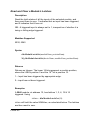
Technman Electronics Ltd.
5000 Series
DLL Driver
USER MANUAL
MANUAL
Contents
Overview................................................................................................... 3
System Set Up............................................................................ 3
Using the 5000Hal.dll and examples.......................................... 4
Use with Multiple Communication Channels ....................................... 5
Maximising System Performance.......................................................... 6
Command Set Summary......................................................................... 8
Set-Up Commands ................................................................................ 11
Open a Communication Channel ............................................. 11
Close a Communication Channel............................................. 14
Identify Module Type ................................................................ 15
Get the Name of a Module ....................................................... 17
Check a Module’s Online Status .............................................. 19
Digital Input Commands....................................................................... 20
Read a Single Input or Output.................................................. 20
Read a Module’s Inputs or Outputs.......................................... 21
Digital Output Commands.................................................................... 23
Write to a Single Digital Output ................................................ 23
Set a Module’s Outputs (Unmasked) ....................................... 24
Set A Module’s Outputs (Masked) ........................................... 26
Analogue Input Commands ................................................................. 28
Read a Single Analogue Input.................................................. 28
Set a Single Input Type ............................................................ 30
Check for New Reading Available............................................ 32
Identify a Single Input Type...................................................... 33
Analogue Output Commands .............................................................. 34
PAGE 1
Set an Analogue Output ........................................................... 34
Error Handling Commands .................................................................. 36
Last Error Number .................................................................... 36
Last Error String ....................................................................... 37
Error Codes............................................................................................ 38
General Errors .......................................................................... 39
Digital Module Errors ................................................................ 40
Analogue Module Errors........................................................... 41
Serial Port Specific Errors ........................................................ 42
5101 PCI Specific Errors .......................................................... 43
Serial Specific Set Up Commands ...................................................... 46
Set Upper Scan Boundary........................................................ 46
Set Lower Scan Boundary........................................................ 47
Serial Specific Digital Input Latch Commands .................................. 48
Set a Module’s Latch Edges..................................................... 48
Peek a Single Latch.................................................................. 51
Read and Clear a Module’s Latches ........................................ 52
Peek Module Latches ............................................................... 54
OptomuxString(text string less checksum)............................... 56
CmdString(text string sent)....................................................... 57
StringResponseAvailable()....................................................... 58
StringResponse()...................................................................... 59
Reference ............................................................................................... 60
Number Base Conversion Table .............................................. 60
Glossary of terms used ............................................................ 61
PAGE 2
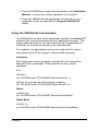
Overview
The 5000 Series Driver has been written as an interface to the
Control-it™ distributed I/O modules, to provide simple yet flexible
commands, make writing your applications easy.
Along with the command set, the driver also offers a performance
boost by taking on the task of polling the modules that would
otherwise be passed to the user.
Immediately after start-up the driver begins interrogating each
address to determine where modules exist and what type they are.
Once a map of the system is established, the driver polls the known
I/O positions, storing an image of their states on the PC. This means
that any ‘Read’ calls can be returned to the application immediately,
without the need to wait for a response from the module. ‘Write’
commands are queued in memory and executed automatically.
The driver also handles soft errors, automatically retrying failed
commands before returning any errors to the user.
In the background, the driver will continue to interrogate unused
addresses, in order to automatically update the system map if a new
module is added. The module is then immediately available to
receive commands.
Each command uses an intuitive name that reflects the operation it
performs and is the same for C/C++, Delphi and Visual Basic.
System Set Up
1. Install the PC interface device.
• If using the Control-it™ 5101 board, ensure it is installed
and running correctly (refer to the 5101 Users Manual for
further details).
• If using a serial port converter, ensure it is running correctly
(refer to the appropriate Users Manual for further details).
2. Connect the Control-it™ remote modules as described in the
appropriate Installation Manual, making careful note of the
addresses.
PAGE 3
3. Use the P5000Demo program as described in the Installation
Manual, to ensure the correct operation of the system.
4. Place the 5000hal.dll and appropriate inclusion file in your
application folder as described in Using the 5000Hal.dll
below.
Using the 5000Hal.dll and examples
The 5000Hal.dll contains all the commands used by the Control-it™
modules and must be accessible by your application program. This
means either placing it in the same directory as the application or
including it in the path command in your autoexec.bat.
For simplicity, the parameters and returns used with the various
commands are all 32-bit integers, unless stated otherwise.
Inclusions
Each language requires a specific external file to be included for
using the driver commands. These directories also contain
examples.
C++
5000Hal.h
(on CD-ROM under \PCSoft\5000 Series Driver\C++)
5000Hal.lib must also be linked during compiling.
(On CD-ROM under \PCSoft\5000 Series Driver\C++)
Delphi
p5000Hal.pas
(on CD-ROM under \PCSoft\5000 Series Driver\Delphi)
Visual Basic
5000Hal.bas
(on CD-ROM under \PCSoft\5000 Series Driver\Visual Basic)
PAGE 4
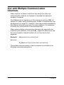
Use with Multiple Communication
Channels
When required, a system may be set up using more than one
communication channel, for instance to increase the maximum
number of modules.
The 5000Hal.dll can handle up to 99 serial ports and four 5101 HiSpeed PCI cards, vastly increasing the number of modules that may
be attached to a single PC. However, since two modules attached to
two different channels may have the same address, it is necessary
to modify the command set to accommodate this.
When using multiple communication channels, all commands are
modified by the addition of the prefix M_ (capital M underscore) and
the communication channel number (deviceNum) as the first
argument.
Example:
aIn(moduleNum, positionNum)
becomes
M_aIn(deviceNum, moduleNum, positionNum)
The multiple-channel version of each command is included in the
following command descriptions.
PAGE 5
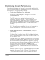
Maximising System Performance
A number of techniques can be used to improve the update rate of
both individual modules and the system as a whole, maximising the
performance of your distributed I/O system.
• Cluster Input Modules at low addresses
Set all input modules, digital or analogue, to the lowest
possible addresses.
The 5000 series driver polls all input modules in the
foreground, starting at address 0, up to the highest known
input module address. As the driver must check that an
address is used, and that an input module is attached, keeping
the highest input address as low as possible reduces this
checking.
NB – The performance gain from this may not be enough to
warrant changing from more intuitive address choices.
• Set the Upper and Lower Scan Boundaries (COM port
systems only)
Set Upper Scan Boundary (page 46) to the highest address
used in the system and the Lower Scan Boundary (page 47) to
the first address used.
The 5000 series driver updates its ‘system map’ by continually
checking all possible module addresses one-by-one. Although
this occurs in the background of normal operation, requiring
few resources, each unused address must time-out before the
driver can return to the foreground. Setting the scan
boundaries removes the need for the 5000 series driver to
check, and time-out, addresses that will never be used in the
system.
Hi-Speed systems only have 31 possible addresses and 690k
baud rate (as opposed to the COM port’s 256 address and
115.2k baud rate maximum), so do not require this option.
PAGE 6
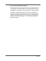
• Turn off unused Analogue Inputs
By setting the input type (page 30) of any unused inputs to 0
i.e. disabled, the refresh rate for a particular position can be
increased to a maximum of 10 per second (1 input enabled).
Analogue modules update their internal input registers by
continually sampling all enabled inputs. Each sample takes
100mS, so a single-ended (16 I/P) module, with all positions
enabled, will take a maximum of 1.6 seconds to update a
particular position.
PAGE 7
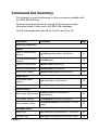
Command Set Summary
The following is a quick reference for the commands available with
the 5000 Series Driver.
All parameters and returns are signed-32-bit-integers unless
otherwise stated. Floats are to the IEEE 32bit standard.
On/Off style parameters should be 1 for On and 0 for Off.
Description
Command
Page
Universal Commands
Set-Up
Open a communication
channel
openDevice(deviceNum, baudRate)
11
Close a communication
channel
closeDevice()
13
Identify a module type
moduleType(moduleNum)
15
Identify a module name
moduleName(moduleNum)
17
Check online status
moduleOnlineStatus (moduleNum)
19
Read single digital
position
dIn(moduleNum, positionNum)
20
Read whole module
dInModule(moduleNum)
21
Write single digital output
dOut(moduleNum, positionNum,
desiredState)
23
Write whole module
dOutModule(moduleNum, outData )
24
Write masked outputs
dOutModuleMasked(moduleNum, outData,
mask)
26
Read input
aIn(moduleNum, positionNum). Float return
28
Set input type
aSetType(moduleNum, positionNum, type)
30
Digital Input
Digital Output
Analogue Inputs
PAGE 8
Identify input type
aGetType(moduleNum, positionNum)
33
New reading available
aNewReading(moduleNum, positionNum)
32
aOut(moduleNum, outputNum,
outputCurrent)
34
Last error number
getLastErrNum()
36
Last error string
getLastErrStr()
37
Analogue Outputs
Set output
Error Handling
Serial Port Specific Commands
Set-Up
Set upper scan boundary
setUpperBoundary(lastModule)
46
Set lower scan boundary
setLowerBoundary(firstModule)
47
Set latches
dInSetLatch(modulenum, latchMask)
48
Read and clear single
latch
dInLatchGet(modulenum, positionNum)
50
Peek single latch
dInLatchPeek(modulenum, positionNum)
51
Read and clear module
latches
dInModuleLatchGet(comNumber,
modulenum)
52
Peek module latches
dInModuleLatchPeek(comNumber,
modulenum)
54
Digital Input Latches
Direct Serial commands (for advanced users)
Send an Optomux cmd
OptomuxString(text string less checksum)
56
Send an command string
CmdString(text string to send)
57
Check response
available
StringResponseAvailable()
58
Get response
StringResponse() string return
59
Hi-Speed Specific Commands
Status Commands
Check online status
moduleOnlineStatus(moduleNum)
19
PAGE 9
Multiple Interface Commands
Above commands begin with M_, and
deviceNum is first parameter
When more than one
High-Speed card or serial e.g.
port is used
M_aIn(deviceNum, moduleNum,
positionNum)
PAGE 10
5
Set-Up Commands
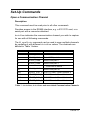
Open a Communication Channel
Description
This command must be used prior to all other commands.
Provides access to the RS485 interface, e.g. a 5101 PCI card, or a
serial port with a converter attached.
deviceNum indicates the communication channel you wish to capture
for use with all following commands.
The M_openDevice command can be used to open multiple channels
by repeating it with different deviceNum values. The channels are
defined in Table 1 below.
deviceNum
deviceName
Communication Channel
0
DEVICE_CLOSED Invalid device number
1
DEVICE_COM1
Serial COM port 1
2
DEVICE_COM2
Serial COM port 2
3
DEVICE_COM3
Serial COM port 3
…
… continues as above …
99
DEVICE_COM99
100
DEVICE_5101_0 5101 PCI card – Board Number 0
101
DEVICE_5101_1 5101 PCI card – Board Number 1
102
DEVICE_5101_2 5101 PCI card – Board Number 2
103
DEVICE_5101_3 5101 PCI card – Board Number 3
Serial COM port 99
Table 1 - deviceNum, deviceName and associated Communication Channels
PAGE 11
The second parameter defines the baud rate when opening a serial
port. For systems using Hi-Speed cards, this value is ignored and
can be left as 0. Table 2 details the available baud rates.
Baud rate
0 [Hi-Speed cards only]
1200
2400
4800
9600
19,200
38,400
57,600
115,200
Table 2- Available Baud Rates for Serial Channels
Syntax
openDevice(deviceNum, baud-rate)
M_openDevice(deviceNum, baud-rate)
Returns
No Return
PAGE 12
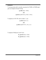
Examples
To communicate with a module connected to COM2, at 19200 baud,
you must capture that port using
openDevice(2, 19200)
OR
openDevice(DEVICE_COM2, 19200)
To capture a 5101 PCI card, number 1, use
openDevice(101, 0)
OR
openDevice(DEVICE_5101_0, 0)
To capture COM ports 2 and 3 use
M_openDevice(2, 19200)
M_openDevice(3, 19200)
PAGE 13
Close a Communication Channel
Description
This command must be used before terminating the control program
to avoid system errors.
Closes the communication channel and frees the memory space.
Syntax
closeDevice()
M_closeDevice(deviceNum)
Returns
No Return.
Examples
To release the communication channel before terminating your
application, use
closeDevice()
To release COM2, when more than one channel is open, use
M_closeDevice(2)
PAGE 14
Identify Module Type
Description
Identify the type of module at the given moduleNum.
Modules Supported
All
Syntax
moduleType(moduleNum)
M_moduleType(deviceNum, moduleNum)
PAGE 15
Returns
Returns an integer identifying the module type as listed in Table 3.
When viewed as a hexadecimal number, each pair of digits identifies
the positions’ type, e.g. 10(hex) is 8 outputs and 20(hex) is 8 inputs.
Return
(Hex)
Module Type
Description
I/O
Configuration
0000 No board found
1010
5020
Digital output module
16 Digital O/P
1020
5030
Digital I/O module
8 Digital O/P
8 Digital I/P
2020
5040
Digital input module
16 Digital I/P
0040
5050/8
Differential analogue input
module with no Outputs.
8 Analogue I/P
4040
5050/16
Single-Ended analogue input
module with no Outputs.
16 Analogue I/P
3040
5050/8/OUT
Differential analogue input
module with 2 Outputs.
8 Analogue I/P
2 Analogue O/P
5040
5050/16/OUT
Single-Ended analogue input
module with 2 Outputs.
16 Analogue I/P
2 Analogue O/P
Table 3 - Module Type returns
Examples
With a 5030 I/O module at address 12, using
modID = moduleType(12)
modID will contain the value 1020(hex).
PAGE 16
Get the Name of a Module
Description
Return a string, naming the module at moduleNum.
Modules Supported
All
Syntax
moduleName(moduleNum)
M_moduleName(deviceNum, moduleNum)
Returns
Returns one of the following strings:
• NotPresent
• NotScanned
• Unknown
• 5020
• 5030
• 5040
• 5050Single
• 5050Diff
• 5050SingleOut
• 5050DiffOut
PAGE 17
Examples
With a 5030 I/O module at address 12, using
modName = moduleName(12)
modName will point to the string “5030”.
PAGE 18
Check a Module’s Online Status
Description
This command is only available on Hi-Speed systems
Returns 1 if module is, or has been online. Used to diagnose the
system if an error is encountered, e.g. after communication time-out
error, moduleOnlineStatus can be checked to discover whether
module has ever been connected.
Modules Supported
All
Syntax
moduleOnlineStatus (moduleNum)
M_moduleOnlineStatus (deviceNum, moduleNum)
Returns
Returns an Integer.
1 – Module is, or has been, online.
0 – Module has never been online.
Examples
To check the online status on module 14, use
online = moduleOnlineStatus(14)
If online contains 1, the module is, or has been, online.
PAGE 19
Digital Input Commands
Read a Single Input or Output
Description
Reads the state of a single digital input position.
This command can also be used to read back the state of digital
outputs.
Modules Supported
5020, 5030, 5040
Syntax
dIn (moduleNum, positionNum)
M_dIn (deviceNum, moduleNum, positionNum)
Returns
Returns an integer where 0 is false and 1 is true.
Examples
To find the state of input 5 on the module at address 12, use
inState = dIn (12, 5)
If inState equals 1, the input is high.
PAGE 20
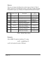
Read a Module’s Inputs or Outputs
Description
Read all the states of a module's inputs.
This command can also be used to read the module’s output states.
Modules Supported
5020, 5030, 5040
Syntax
dInModule(moduleNum)
M_dInModule(deviceNum, moduleNum)
Returns
Returns an Integer. The lower 16 bits represent a module position,
where bit 0 represents position 0 and bit 15 represents position 15.
0 = Off
1 = On
Examples
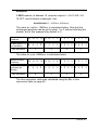
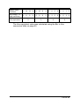
A 5040 module, at address 12, has inputs 1, 3, 6, 12 & 15 on. Using
inState = dInModule(12)
inState will hold the value 904AHex, as calculated below.
PAGE 21
Module Input
Positions
15 14 13 12 11 10
Input state (1 is
on) as Binary
1
Hex equivalent
0
0
9
1
0
0
0
9
8
7
6
5
4
3
2
1
0
0
0
0
1
0
0
1
0
1
0
4
The Hex equivalent value was calculated using the Bin to Hex
conversion table on page 60.
PAGE 22
A
Digital Output Commands
Write to a Single Digital Output
Description
Sets the state of a single digital output.
desiredState is an integer where 0 is OFF and 1 is ON.
NB Since desiredState is an integer, any value other than 0 is taken
as ON.
Modules Supported
5020, 5030
Syntax
dOut(moduleNum, positionNum, desiredState)
M_dOut(deviceNum, moduleNum, positionNum, desiredState)
Returns
No return.
Examples
To turn on output 3 on the module at address 6, use
dOut(6, 3, 1)
To turn off output 15 on the module at address 2, use
dOut(2, 15, 0)
PAGE 23
Set a Module’s Outputs (Unmasked)
Description
Sets the state of all the module's outputs.
The lower 16 bits of outData represent the output positions. Bit 0
represents position 0 and bit 15 represents position 15.
0 = Off
1 = On
With this command, all outputs must be set every time. Therefore, to
leave a position in its current state, its previous setting must be
repeated.
Modules Supported
5020, 5030
Syntax
dOutModule(moduleNum, outData)
M_dOutModule(deviceNum, moduleNum, outData)
Returns
No returns.
PAGE 24
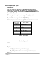
Examples
A 5020 module, at address 12, requires outputs 1, 3, 6, 12 & 15 ON,
and the rest OFF. Use
dOutModule(12, 904Ahex)
The value for outData, 904Ahex, is calculated below.
Module Output
Positions
15 14 13 12 11 10
Output state (1 is
on) as Binary
1
Hex equivalent
0
0
9
1
0
0
0
9
8
7
6
5
4
3
2
1
0
0
0
0
1
0
0
1
0
1
0
4
A
The Hex equivalent value was calculated using the Bin to Hex
conversion table on page 60.
PAGE 25
Set A Module’s Outputs (Masked)
Description
Same as ‘Set Module’s Outputs (Unmasked)’ with the addition of a
mask, allowing positions to remain unchanged without having to
repeat their previous settings.
outData is the same as for ‘Set Module’s Outputs (Unmasked)’
Only positions with a 1 set in mask will be altered by this call.
The lower 16 bits of mask represent the output positions. Bit 0
represents position 0 and bit 15 represents position 15.
0 - Position remains unchanged
1 - Position will respond to call
Modules Supported
5020, 5030
Syntax
dOutModuleMasked(moduleNum, outData, mask)
Returns
No Returns
PAGE 26
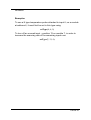
Examples
A 5020 module, at address 12, requires outputs 1, 6 & 12 ON, 3 &
15 OFF, and all others unchanged. Use
dOutModule(12, 1042hex, 904Ahex)
The value for outData, 1042hex, is calculated below. Note that the
unchanged positions can be set to either 1 or 0, without affecting the
module, but in this example they default to 0.
Module Output
Positions
15 14 13 12 11 10
9
8
7
6
5
4
3
2
1
0
Output state (1 is
on) as Binary
0
0
0
0
1
0
0
0
0
1
0
0
Hex equivalent
0
1
0
0
1
0
4
2
The value for mask, 904Ahex, is calculated below.
Module Output
Positions
15 14 13 12 11 10
9
8
7
6
5
4
3
2
1
0
Outputs to be
changed (as
Binary)
1
0
0
0
1
0
0
1
0
1
0
Hex equivalent
0
0
9
1
0
0
0
4
A
The Hex equivalent value was calculated using the Bin to Hex
conversion table on page 60.
PAGE 27
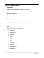
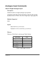
Analogue Input Commands
Read a Single Analogue Input
Description
Reads the state of a single analogue input position.
A position’s input type must be set before it can be read correctly.
By default this is 0-10Vdc. See Set a Single Input Type (page 30).
Modules Supported
5050
Syntax
aIn(moduleNum, positionNum)
M_aIn(deviceNum, moduleNum, positionNum)
Returns
Returns a 32 bit float, in units as per Table 4 below.
Input Range
Units
+/- 1V
Volts
+/- 10V
Volts
+/- 20mA
mA
J 0 – 760oC
o
C
K 0 - 1000oC
o
T 100-400oC
o
C
C
Table 4 - Input ranges and units
PAGE 28
Examples
A module on a Hi-Speed system at address 12 has 4.8540V on
input 3. The input is set to the 10V range. Using
voltage = aIn(12, 3)
voltage will contain 4.8540.
PAGE 29
Set a Single Input Type
Description
Sets and stores the input type of each position in non-volatile
memory on the module as per table 5. This must match the Input
Type Jumper settings as described in Jumper Configuration in the
Installation Manual.
This command can also turn unused positions off, thereby
increasing the module’s update rate per enabled input.
By default the Input Type is set to 2 (0-10Vdc).
The input type must be set correctly before the input can be read.
Input Type
Character
Input Range
0
Disabled input
1
+/- 1V
2
+/- 10V
3
+/- 20mA
4
J
0 - 760oC
5
K
0 - 1000oC
6
T
100-400oC
Table 5 - Input Types
Modules Supported
5050
Syntax
aSetType(moduleNum, positionNum, type)
M_aSetType(deviceNum, moduleNum, positionNum, type)
Returns
PAGE 30
No return
Examples
To use a K type temperature probe attached to input 6, on a module
at address 4, it must first be set to this type using
setType(4, 6, 5)
To turn off an unused input – position 13 on module 7, in order to
increase the scanning rate of the remaining inputs use
setType(7, 13, 0)
PAGE 31
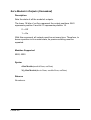
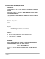
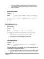
Check for New Reading Available
Description
Allow checking to see if a new reading is available for an analogue
position.
newReading is set to 0 after aIn is called, and is only set to 1 after a
new sample is available.
This command is used to eliminate repeated aIn calls to the same
sample.
Modules Supported
5050
Syntax
aNewReading(moduleNum, positionNum)
Returns
0 - no new reading is available since the last aIn call.
1 - a new reading is available.
Examples
Before reading input 4, on module 16, you can check that a new
reading is available (since last read), by using
ready = newReading(16, 4)
If ready is 0, no new sample is available since the input was last
read.
PAGE 32
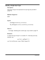
Identify a Single Input Type
Description
Returns an integer that represents the input type as per table 5
(page 30).
Modules Supported
5050
Syntax
aGetType(moduleNum, positionNum)
M_aGetType(deviceNum, moduleNum, positionNum)
Returns
An integer, identifying the module type, as per table 5, page 30.
Examples
To check the type of input 5, on module 15 – that was previously
disabled, use
typeCheck = getType(15, 5)
typeCheck will be zero, as per Table 6 (page 34).
PAGE 33
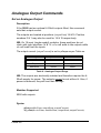
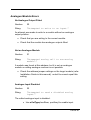
Analogue Output Commands
Set an Analogue Output
Description
If the 5050 has two optional 4-20mA outputs fitted, this command
sets their output current.
The outputs are located at positions (outputNum) 14 &15. Position
numbers 0 & 1 may also be used for 14 & 15 respectively.
NB: On 16 input (single ended) modules, these positions do not
clash with input positions 14 & 15. aOut will write to the outputs while
aIn will read from the inputs.
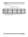
The output current (outputCurrent) is set in µAmps as per Table xx.
Range
outputCurrent
Actual Current
Minimum
3500
3.5mA
Step
1
1µA
Maximum
20000
20mA
Table 6 - Analogue Output Range
NB: The outputs are electrically isolated and therefore require the 420mA supply for power. The outputs cannot be set without it. Also, if
power is removed, they will lose their settings.
Modules Supported
5050 with outputs
Syntax
aOut(moduleNum, outputNum, outputCurrent)
M_aOut(deviceNum, moduleNum, outputNum, outputCurrent)
PAGE 34
Returns
No return
Examples
To set output 14, on module 23, to 8.32mA, use
aOut(23, 14, 8320)
PAGE 35
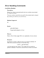
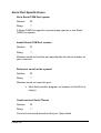
Error Handling Commands
Last Error Number
Description
Returns an integer representing the last error number encountered.
If 0, there is no error.
The error number is set after every call to the network and is cleared
by a call to getLastErrStr() or resetErrNum().
Modules Supported
All
Syntax
getLastErrNum()
M_getLastErrNum(deviceNum)
Returns
Refer to Error Codes (page 38) for an explanation of error returns.
Examples
An attempt is made to read an input on a module at address 12.
When the command execution is checked using
cmdChk = getLastErrStr()
cmdChk holds the error code 3. This means that no module is
present at address 12 and the command has not been successful.
PAGE 36
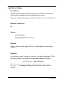
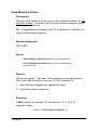
Last Error String
Description
Returns a string representing the last error number encountered.
Use this call to display an error message to the user.
The error string is cleared by a call to getLastErrStr() or resetErrNum().
Modules Supported
All
Syntax
getLastErrStr()
M_getLastErrStr(deviceNum)
Returns
Refer to Error Codes (page 38) for an explanation of error string
returns.
Example
An attempt is made to read an input on a module at address 12 but
the error number 3 is returned by getLastErrNum(). By using
txbMsg.Caption = getLastErrStr()
the "Attempted to access a module that is not
present." message is displayed to the user in the text box
txbMsg.
PAGE 37
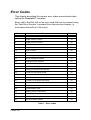
Error Codes
This chapter describes the various error codes encountered when
calling the Control-it™ modules.
Every call to the DLL will set an error code that can be viewed using
the ‘Last Error Number’ command from the previous chapter. In
most cases this will be 0 (No error).
Error code
Description
Page
0
No error
39
1
Illegal module number
39
2
Illegal position number
39
3
Module not present
39
4
Illegal board number
39
10
Write to input
40
11
Not a digital module
40
20
No analogue output fitted
41
21
Not an analogue module
41
22
Analogue input disabled
41
30
Not a serial COM port system
42
31
Invalid serial COM port number
42
32
Serial port could not be opened
42
33
Could not start serial thread
42
34
Module number outside range
42
40
Windriver not found
43
41
Control-it 5101 board not found
43
42
Non-functional Control-it 5101 board detected
43
43
Null handle used
43
44
Invalid handle used
43
45
Wrong version of Windriver
43
46
5101 not opened
43
47
Incorrect 5101 number
43
50
Not a Hi-Speed system
43
Table 7 - Error codes
PAGE 38
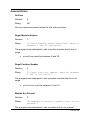
General Errors
No Error
Number:
0
String:
Nil
No error was encountered when the call was executed.
Illegal Module Number
Number:
1
String:
"Illegal module number specified. Must be
between 0 and 30 inclusive."
The program has attempted to call a module number that is out of
range.
• moduleNum must be between 0 and 30.
Illegal Position Number
Number:
2
String:
"Illegal position number. Must be between
0 and 15 inclusive."
The program has attempted to call a position number that is out of
range.
• positionNum must be between 0 and 15.
Module Not Present
Number:
3
String:
"Attempted to access a module that is not
present.”
The program has attempted to call a module that is not present.
PAGE 39
• Check the address jumper settings on the target module
(refer Installation Guide in this manual). moduleNum must
equal this setting.
Illegal Board Number
Number:
4
String:
"Illegal board number. Must be between 0
and 3 inclusive.”
The program has attempted to use a 5101 PCI card number that is
not valid.
Digital Module Errors
Write to Input
Number:
10
String:
"Attempted to write to an input.”
An attempt was made to write to an input, so no action occurs
• Check that you are writing to the correct module.
• Check that the module has digital outputs fitted.
Not a Digital Module
Number:
11
String:
"Attempted digital call to non-digital
module.”
A module was found at this address, but it is not a digital module so
calling digital routines is not possible.
• Check the address jumper settings on the target module (refer
Installation Guide in this manual). moduleNum must equal this
setting.
PAGE 40
Analogue Module Errors
No Analogue Output Fitted
Number:
20
String:
"Attempted to write to an input.”
An attempt was made to write to a module without an analogue
output position.
• Check that you are writing to the correct module.
• Check that the module has analogue outputs fitted.
Not an Analogue Module
Number:
21
String:
"Attempted analog call to non-analog
module.”
A module was found at this address, but it is not an analogue
module so calling analogue routines is not possible.
• Check the address jumper settings on the target module (refer
Installation Guide in this manual). moduleNum must equal this
setting.
Analogue Input Disabled
Number:
22
String:
"Attempted to read a disabled analog
input.”
The called analogue input is disabled.
• Use aSetType(modNum, posNum) to enable input.
PAGE 41
Serial Port Specific Errors
Not a Serial COM Port system
Number:
30
String:
"”
A Serial COM Port specific command was used on a non Serial
COM Port system.
Invalid Serial COM Port number
Number:
31
String:
""
Windows could not find the port specified by the device number on
your computer.
Serial port could not be opened
Number:
32
String:
""
Windows could not open the port.
• Most likely another program (or instance of this DLL) is
using it.
Could not start Serial Thread
Number:
33
String:
""
Could not start serial thread for this port. Open failed.
PAGE 42
Module number outside range
Number:
34
String:
""
Tried to access a module that is outside the range of modules
defined by setLowerBoundary and setUpperBoundary.
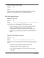
5101 PCI Specific Errors
WinDriver not found
Number:
40
String:
"Could not find WinDriver on the system”
The WinDriver for the Control-it™ 5101 was not found.
• Check that windrvr.vxd is in the windows\system\vmm32
directory for Win 95 & 98, or windrvr.sys is in the
windows\system32\drivers directory for Win 2000 & NT.
• If necessary, re-install driver software from 5000 SDK CDROM.
Control-it™ 5101 Board not found
Number:
41
String:
"No 5101 High-Speed cards detected.”
There were no PCI cards found with DevId & VendorId matching
5101.
• Ensure the card is properly fitted in the PCI slot.
• Install the card in another empty PCI slot.
• Use ‘Add New Hardware’ in the Control Panel to install
manually.
PAGE 43
Non-functional Control-it™ 5101 board found
Number:
42
String:
"5101 Modules detected. Could not open
any.”
A card was found, but it was not a functional 5101. This error will
occur if the last application did not close the board correctly.
• Restart the computer
• Ensure close5101Hal is called at the end of the application.
Null Handle Used
Number:
43
String:
"Call made with a null handle (i.e. a
closed board)”
A call was made to a channel that has not been opened.
• Ensure that openDevice(deviceNum) is the first call made to the
board.
• Use getLastErrNum immediately after openDevice(deviceNum) to
verify that the channel has opened correctly. The return value
must be 0.
Invalid handle Used
Number:
44
String:
"Call made with an invalid handle (i.e.
not between 0 - 3)”
A call was made to a channel using an invalid deviceNum. Must be
between 1 and 103 inclusive.
• Check that code uses the correct deviceNum.
PAGE 44
Wrong version of Windriver
Number:
45
Strings:
"Windriver was found, but it was the
wrong version for this DLL”
Windriver version on the system is older than the expected version.
Use the 5000 SDK CD-ROM to repair your installation.
5101 not opened
Number:
46
Strings:
"Opened at least 1 5101 module - but it
was not functional.”
No 5101s could be opened.
Incorrect 5101 number
Number:
47
Strings:
"Could not open requested board.”
A 5101 was opened, but it was not the correct board number
requested.
Not a Hi-Speed system
Number:
50
Strings:
"Call made to a 5101 specific routine
with a device that is not a 5101.”
A 5101 specific command was used on a non Hi-Speed system.
PAGE 45
Serial Specific Set Up Commands
Set Upper Scan Boundary
Description
Allows the highest address used in a network to be identified. This
increases system performance by removing the need to scan
unused addresses at the top of the range.
lastModule is the highest address used, inclusive.
Modules Supported
All
Syntax
setUpperBoundary(lastModule)
M_setUpperBoundary(lastModule)
Returns
No return.
Examples
A system has modules installed with addresses ranging from 3 to
24. To prevent scanning modules that do not exist, set the upper
boundary using
setUpperBoundary(24)
PAGE 46
Set Lower Scan Boundary
Description
Allows the lowest address used in a network to be identified. This
increases system performance by removing the need to scan
unused addresses at the bottom of the range.
firstModule is the lowest address used, inclusive.
Modules Supported
All
Syntax
Boundary(firstModule)
M_setLowerBoundary(firstModule)
Returns
No return.
Examples
A system has modules installed with addresses ranging from 3 to
24. To prevent scanning modules that do not exist, set the lower
boundary using
setLowerBoundary(3)
PAGE 47
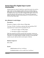
Serial Specific Digital Input Latch
Commands
Latched inputs are used to identify an event that may be too quick to
read via the normal scanning method. Once set to either rising or
falling edge, an input’s latch register will go high and stay high after
that edge is seen, even if the input changes state again, and is only
reset low after the latch has been read. This gives the operating
system the ability to monitor narrow pulses or to check for an event
in a less time-critical way.
Set a Module’s Latch Edges
Description
Set inputs to trigger on either rising or falling edge.
The lower 16 bits of latchEdges represent the input positions. Bit 0
represents Pos 0 and the bit 15 represents Pos 15.
1 – Set input to trigger on falling edges
0 - Set input to trigger on rising edges
With this command, all inputs must be set every time, however an
input may still be read as normal using dIn(moduleNum, positionNum).
Therefore, once edge latching is started, all inputs on the specified
module may be read as either normal inputs or latches.
Modules Supported
5030, 5040
Syntax
dInSetLatch(moduleNum, latchEdges)
M_dInSetLatch(deviceNum, moduleNum, latchEdges)
PAGE 48
Returns
No return.
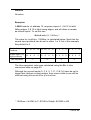
Examples
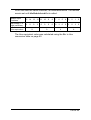
A 5040 module, at address 12, requires outputs 1, 6 & 12 to latch
falling edges, 3 & 15 to latch rising edges, and all others to remain
as normal inputs. To set this use
dInSetLatch (12, 1042hex) *
The value for latchEdges, 1042hex, is calculated below. Note that the
normal input positions can be set to either 1 or 0, but in this example
they default to 0.
Module Output
Positions
15 14 13 12 11 10
Output state (1 is
high) as Binary
0
Hex equivalent
0
0
1
1
0
0
0
9
8
7
6
5
4
3
2
1
0
0
0
0
1
0
0
0
0
1
0
4
2
The Hex equivalent value was calculated using the Bin to Hex
conversion table on page 60.
Although the normal inputs (0, 2, 4, 5, 7-11, 13 & 14) have be set to
trigger their latches on rising edges, their current state is can still be
returned using dIn(moduleNum, positionNum).
* 1042hex = 0x1042 in C, $1042 in Delphi, $H1042 in VB.
PAGE 49
Read and Clear a Single Latch
Description
Read the latch state of the selected input and then reset to zero. 1
indicates that the input has been triggered, and 0 indicates that it
has not.
NB - A triggered input is always set to 1, irrespective of whether it is
rising or falling edge triggered.
Modules Supported
5030, 5040
Syntax
dInLatchGet(moduleNum, positionNum)
M_dInLatchGet(deviceNum, moduleNum, positionNum)
Returns
1 – Input has been triggered by appropriate edge.
0 – input has not been triggered.
Examples
Input 3 on the module at address 13 is set to rising edge latch.
Using
edgeCheck = dInLatchGet(13, 3)
edgeCheck contains a 1. This indicates that a rising edge has
occurred at the input since it was last read. Input 3’s latch state is
now automatically reset to 0.
PAGE 50
Peek a Single Latch
Description
Read the latch state of the selected input but do not reset to zero. 1
indicates that the input has been triggered, and 0 indicates that it
has not.
NB - A triggered input is always set to 1, irrespective of whether it is
rising or falling edge triggered.
Modules Supported
5030, 5040
Syntax
dInLatchPeek(moduleNum, positionNum)
M_dInLatchPeek(deviceNum, moduleNum, positionNum)
Returns
1 – Input has been triggered by appropriate edge.
0 – input has not been triggered.
Examples
Input 3 on the module at address 13 is set to rising edge latch.
Using
edgePeek = dInLatchPeek(13, 3)
edgePeek contains a 1. This indicates that a rising edge has occurred
at the input since it was last read. Input 3’s latch state remains set
until dInLatchGet is called.
PAGE 51
Read and Clear a Module’s Latches
Description
Read the latch states of all the inputs of the selected module, and
then reset them to zero. 1 indicates that an input has been triggered,
and 0 indicates that it has not.
NB - A triggered input is always set to 1, irrespective of whether it is
rising or falling edge triggered.
Modules Supported
5030, 5040
Syntax
dInModuleLatchGet(moduleNum, positionNum)
M_dInModuleLatchGet(deviceNum, moduleNum, positionNum)
Returns
Returns an Integer. The lower 16 bits represent a module position,
where the LSB is position 0 and the 16th bit is position 15.
1 – Input has been triggered by appropriate edge.
0 – input has not been triggered.
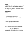
Examples
A 5040 module, at address 12, has latches 1, 3, 6, 12 & 15
triggered. Using
inState = dInModuleLatchGet(12)
inState will hold the value 904AHex, as calculated below. The latches
are then reset to zero.
PAGE 52
Module Input
Positions
15 14 13 12 11 10
Input state (1 is
high) as Binary
1
Hex equivalent
0
0
9
1
0
0
0
9
8
7
6
5
4
3
2
1
0
0
0
0
1
0
0
1
0
1
0
4
A
The Hex equivalent value was calculated using the Bin to Hex
conversion table on page 60.
PAGE 53
Peek Module Latches
Description
Read the latch states of all the inputs of the selected module, but do
not reset to zero. 1 indicates that an input has been triggered, and 0
indicates that it has not.
NB - A triggered input is always set to 1, irrespective of whether it is
rising or falling edge triggered.
Modules Supported
5030, 5040
Syntax
dInModuleLatchPeek(moduleNum, positionNum)
M_dInModuleLatchPeek(deviceNum, moduleNum,
positionNum)
Returns
Returns an Integer. The lower 16 bits represent a module position,
where the LSB is position 0 and the 16th bit is position 15.
1 – Input has been triggered by appropriate edge.
0 – input has not been triggered.
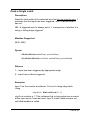
Examples
A 5040 module, at address 12, has latches 1, 3, 6, 12 & 15
triggered. Using
inState = dInModuleLatchPeek(12)
PAGE 54
inState will hold the value 904AHex, as calculated below. The latches
remain set until dInModuleLatchGet is called.
Module Input
Positions
15 14 13 12 11 10
Input state (1 is
high) as Binary
1
Hex equivalent
0
0
9
1
0
0
0
9
8
7
6
5
4
3
2
1
0
0
0
0
1
0
0
1
0
1
0
4
A
The Hex equivalent value was calculated using the Bin to Hex
conversion table on page 60.
PAGE 55
OptomuxString(text string less checksum)
Description
An optomux command can be sent directly to a desired module.
Modules Supported
All
Syntax
The first character needs to be the > sign. No checksum or carriage
return is necessary.
OptomuxString(text string less checksum)
M_OptomuxString(deviceNum,text string less checksum)
Returns
No return from command sent, but module will respond. See
StringResponseAvailable() and StringResponse()
Examples
Turn on outputs 8 and 10 on 5030.
optomuxString('>01J0500')
If multiple channels were in use then the command would be
M_optomuxString(deviceNum,'>01J0500')
PAGE 56
CmdString(text string sent)
Description
A text string can be sent directly out a serial channel. It is not limited
to Optomux protocol.
Modules Supported
All 5000 series modules, and also other serial devices.
Syntax
The text is free format.
CmdString(text string)
M_CmdString(deviceNum,text string)
Returns
No return from command sent. A response from the remote unit can
be checked for by using StringResponseAvailable() and
StringResponse()
Examples
Send text out through the 5258 adressable converter at address 7.
The converter is selected and “ hello world ” is sent through the
converter. “HeAdEr07T” causes the 5258 to open its RS232
channel. “HeAdEr07F” closes the 5258 channel once “ hello world “
has passed through.
CmdString('HeAdEr07T hello world HeAdEr07F ')
If multiple channels were in use then the command would be
M_CmdString(DeviceNum,'HeAdEr07T hello world HeAdEr07F ')
PAGE 57
StringResponseAvailable()
Description
Allows checking for a response from the remote module to an
OptomuxString(), or CmdString().
StringResponseAvailable() is set to 0 if no response received, and 1
if a response received. The receiving routine waits for a complete
message to be received before returning a 1.
Modules Supported
All 5000 series modules, and also other serial devices.
Syntax
StringResponseAvailable();
M_StringResponseAvailable(deviceNum);
Returns
0 - no response available
1 – response available
Examples
Check for response and then collect data.
if (StringResponseAvailable()) = 1 then
yourDataString := StringResponse()
PAGE 58
StringResponse()
Description
Allows reading back a response from the remote module to an
OptomuxString(), or CmdString() command.
StringResponseAvailable() is set to 0 if no response received, and 1
if a response received. The receiving routine waits for a complete
message to be received before returning a 1.
Modules Supported
All 5000 series modules, and also other serial devices.
Syntax
StringResponse();
M_StringResponse(deviceNum);
Returns
String or string pointer depending on language used.
Examples
Check for response and then collect data.
if (StringResponseAvailable()) = 1 then
yourDataString := StringResponse()
PAGE 59
Reference
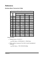
Number Base Conversion Table
Hexadecimal – Binary – Decimal Conversion Table
Hex
Binary
Decimal
Most Significant Bytes
IV
Least Significant Bytes
III
II
I
0
0000
0
0
0
0
1
0001
4096
256
16
1
2
0010
8192
512
32
2
3
0011
12288
768
48
3
4
0100
16384
1024
64
4
5
0101
20480
1280
80
5
6
0110
24576
1536
96
6
7
0111
28672
1792
112
7
8
1000
32768
2048
128
8
9
1001
36864
2304
144
9
A
1010
40960
2560
160
10
B
1011
45056
2816
176
11
C
1100
49152
3072
192
12
D
1101
53248
3328
208
13
E
1110
57344
3584
224
14
F
1111
61440
3840
240
15
Using the table:
• Decimal value = IV+III+II+I
e.g. D42 (Hex) = 0+3328+64+2 = 3394 (Dec)
• Binary value is a group of four bits for each hexadecimal
character.
e.g. D42 (Hex) = 1101,0100,0010 (Bin)
PAGE 60
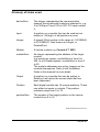
Glossary of terms used
deviceNum
The integer representing the communication
channel that a particular module is attached to, e.g.
3 is COM port 3 and 103 is 5101 PCI card number
3.
Input
A position on a module that can be read but not
written to. Writing to it will produce an error.
Integer
A signed 32-bit number in the range of -147483648
to 2147483647. Also known as Longint, or
DoubleWord.
Module
A remote module e.g. Control-it™ 5030
moduleNum
An integer representing the address of the target
module.
In a serial port system, moduleNum is from 0 to
256. In a Hi-Speed system, moduleNum is from 0
to 30.
The module addresses are set by jumpers on the
modules themselves. Refer to the Installation
Guide in this manual for more detail.
Output
A position on a module that can be written to.
Reading it will return the current state that has
been requested.
Position
Each digital module has 16 unique positions. These
can either be inputs or outputs. The position
numbers range from 0 to 15.
positionNum
The number of the target position on the remote
module from 0 to 15.
5000SeriesDriverManual.doc Rev C
PAGE 61
PAGE 62
PAGE 63
PAGE 64