1
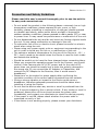
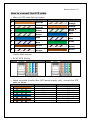
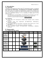
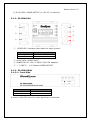
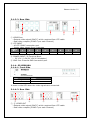
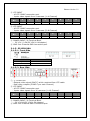
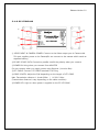
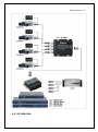
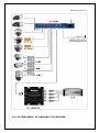
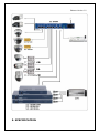
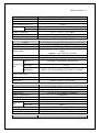
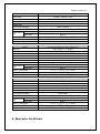
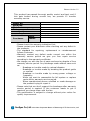
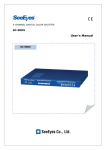
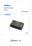
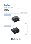
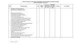
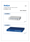
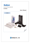
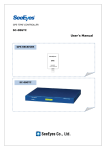
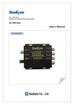
Release Version 1.0 UTP Active Auto Level Adjustment Receiver SC-TP0404, SC-UR0412A(S), SC-UT0412A6 SC-UR0418A(H), SC-UR0818A, SC-UR1618A User's Manual SC-TP0404 SC-UR0412A(S) SC-UT0124A6 SC-UR0418A(H) SC-UR0818A SC-UR1618A Release Version 1.0 Precaution and Safety Guidelines Please read this user’s manual thoroughly prior to use the unit for its easy and convenient use. Do not install the product in the following places: extremely low or high temperature conditions; places exposed to rain, snow, or high humidity; places containing or exposed to oil and gas; places exposed to vibration and shock; places under direct sunlight or exposed to outdoor weather conditions; places exposed to radio waves (RF) or near to power lines. It may cause low performance or malfunction of the unit. Do not disassemble the unit and do not insert any foreign objects inside the unit. It may cause malfunction or damage to the unit. To reduce the risk of fire or electric shock, please be careful on electric shock when using the unit. Please using only power supply units or equipment corresponding to the unit in order to avoid any fire risk or or malfunction of the unit. The optimum ambient temperature for the use of the Device is -10℃ ~ 50℃, and it needs to be careful when the Device is used for both inside and outside the building. Should be careful not to have the lines changed when connecting them. When you connect the operating power line to the Camera, you should confirm if the Camera uses AC or DC power, and for the case of DC power then you should be careful not to have the polarity changed to the wrong one (If you connect the AC Adapter to Transmitter, and connect the DC Adapter to the Receiver, then it would cause a breakdown). Please turn on the switch for power supply after confirming the insulation condition of the control cable connected from the outside. Giving a strong vibration or impact to the Device could cause a breakdown, therefore adequate precautions should be taken when installing or using the Device. Do not use the device when any smoke or smell is produced from the unit. It may be subject to fire or electric shock. If any smoke or smell is produced, please turn off the unit and remove the power cable immediately, and contact your distributor to check the device properly. If the power is not ON, please check whether the power cable is connected correctly or not. If the device is not working properly, please contact your distributor. Release Version 1.0 How to connect the UTP cable 4Pairs of UTP cable Wiring System NO SeeEyes TIA / EIA 568B White & Orange 1 Orange 2 White & Orange Orange 3 Green White & Green 4 White & Green Blue 5 Blue White & Blue 6 White & Blue Green 7 Brown White & Brown White & Brown Brown Please note that the SeeEyes UTP cable wiring method is different from TIA/EIA 568B method. 8 RJ-45 JACK Wiring SeeEyes TIA / EIA 568B Please note that SeeEyes RJ-45 Wiring method is different from TIA/EIA 568B. When using the Junction Box (UTP power supply unit), connect the UTP cable as below. Cable # 1 2 3 4 5 6 7 8 Camera VIDEO (+) VIDEO (-) RS-485 (+) RS-485 (-) CAMERA POWER CAMERA POWER CAMERA POWER CAMERA POWER (+) (+) (-) (-) Receiver or DVR CAMERA 1 (+) CAMERA 1 (-) CAMERA 2 (+) CAMERA 2 (-) CAMERA 3 (+) CAMERA 3 (-) CAMERA 4 (+) CAMERA 4 (-) Release Version 1.0 1. Introduction 1-1. Overview Automatic Level adjustment Active type UTP transmission system is composed of a Transmitter (Camera side), [SC-TP0404 and SC-UT0124A6], and Receivers (DVR side), [SC-UR0412A(S)/ SC-UR0418A(H)/ SC-UR0818A/ SC-UR1618A]. Using this solution, it is possible to transmit video signals for long distance (up to 1.2 Km with Passive balun) over Cat.5 UTP cable. Also due to its automatic video level adjustment function, it is no necessary to adjust gains for the optimum video. ※ SC-UR0412A(S), SC-UR0418A(H), SC-UR0818A, SC-UR1618A can be used with other UTP Transmitters but it is recommended to compose the products as below Product Combination (Refer to No.2-2) 1-2. Features Active type UTP Transmission product with excellent Noise isolation function Automatic video level adjustment (SC-UR0412A(S), UR0418A(H), UR0818A, UR1618A) Using Passive Balun as Transmitter, it transmits video signal up to 1.2 Km over CAT. 5 Dual video outputs (SC-UR0418A(H), UR0818A, UR1618A) Surge protection function (SC-UR0412A(S), UR0418A(H), UR0818A, UR1618A) 2. Components 2-1. Components By model Model Tx. SCUT0124A6 ○ SC-TP0404 ○ Rx. Power ○ SCUR0412A(S) ○ SCUR0418A(H) ○ SC-UR0818A ○ Image Rack mount bracket Power Cord, Adaptor Manual Release Version 1.0 SCUR1618A ○ 2-2. Optimum combination Below combination table is recommended for optimum performance when composing the transmitter and receiver. SC-TP0404 Tx Rx. SC-UR0412A(S) Max. Distance 1200m SC-UR0418A(H) SC-TP0404 SC-UR0818A 1200m SC-UR1618A Passive Balun Transceiver Tx SC-TP0104LD SC-TP0104C Rx. SC-UR0412A(S) SC-UR0418A(H) SC-UR0818A SC-UR1618A Max. Distance 1200m SC-UT0124A6 Tx SC-UT0124A6 Rx. SC-UR0412A(S) SC-UR0418A(H) SC-UR0818A SC-UR1618A Max. Distance 1.2 Km 1.8 Km 3. Product Parts and Peripheral Device Connection 3-1. Part Names and Functions 3-1-1. SC-TP0404 ① ② ③ ④ ① ~ ④ BNC: VIDEO INPUT (4 x BNC / 1~4 Channel) ⑤ Release Version 1.0 ⑤ RJ-45 JACK: VIDEO OUTPUT (1 x RJ-45 / 4 channel) 3-1-2. SC-UR0412A ① ④ ⑤ ② ⑥ ③ ⑦ ④ ① VIDEO LED: Indicate video status for each channel. LED Flickering On Status NO VIDEO VIDEO IN ② RJ-45 JACK: VIDEO INPUT ③ POWER IN: DC 12V / 0.3A(DC 12V/0.5A Adapter) ④ ~ ⑦ BNC-F: 1~4 Channel VIDEO OUTPUT 3-1-3. SC-UR0418AH 3-1-3-1. Front Side LED Flickering On Status NO VIDEO VIDEO IN It turns on the LED when the video signals are connected. Release Version 1.0 3-1-3-2. Rear Side ① ② ③ ① VIDEO OUT - Outputs video signal (BNC-F) which received from UTP cable - Dual video outputs (2 BNC-F per each Channel) ② UTP INPUT - 4P UTP CABLE connection port - Inputs video signals from 4 cameras Cable 1 2 3 4 5 6 7 No. Function CH1 + CH 1 - CH 2 + CH 2 - CH 3 + CH 3 - CH 4 + ④ 8 CH 4 - ③ POWER INPUT: 2P Terminal Block - DC 12V / 0.3A(DC 12V/0.5A Adapter) ④ GND Port: External GND connection port 3-1-4. SC-UR0818A 3-1-4-1. Front Side LED Flickering On Status NO VIDEO VIDEO IN It turns on the LED when the video signals are connected. 3-1-4-2. Rear Side ① ② ③ ④ ①, ③ VIDEO OUT - Outputs video signal (BNC-F) which received from UTP cable - Dual video outputs (2 BNC-F per each Channel) ⑤ ⑥ Release Version 1.0 ② UTP INPUT - 4P UTP CABLE connection port - Inputs video signals from 4 cameras (1~4 Channel) Cable 1 2 3 4 5 6 No. Function CH1 + CH 1 - CH 2 + CH 2 - CH 3 + CH 3 ④ UTP INPUT - 4P UTP CABLE connection port - Inputs video signals from 4 cameras (5~8 Channel) Cable 1 2 3 4 5 6 No. Function CH1 + CH 1 - CH 2 + CH 2 - CH 3 + CH 3 - 7 8 CH 4 + CH 4 - 7 8 CH 4 + CH 4 - ⑤ POWER INPUT: 2P Terminal Block - DC 12V / 0.5A(DC 12V/1.0A Adapter) ⑥ GND Port: External GND connection port 3-1-5. SC-UR1618A 3-1-5-1. Front Side LED Flickering On Status NO VIDEO VIDEO IN 3-1-5-2. Rear Side ① ② ③ ①, ③ VIDEO OUT - Outputs video signal (BNC-F) which received from UTP cable - Dual video outputs (2 BNC-F per each Channel) ② UTP INPUT - 4P UTP CABLE connection port - Inputs video signals from 16 cameras (1~16 Channel) Cable 1 2 3 4 5 6 7 No. Function CH1 + CH 1 - CH 2 + CH 2 - CH 3 + CH 3 - CH 4 + ④ POWER INPUT: 2P Terminal Block - DC 12V/1A(DC 12V/1.5A Adapter) ⑤ GND Port: External GND Connection port ④ ⑤ 8 CH 4 - Release Version 1.0 3-1-6. SC-UT0124A6 ① ② ④ ⑤ ⑥ ③ ① VIDEO INPUT & CAMERA POWER: Connect to the Video output port in Camera side. This port supplies power to the Camera(Do not connect to the camera which needs an separate battery.) ②RS-485: RS-485 DATA Connection port(Be careful the polarity when you connect) ③POWER IN: Using when you connect Extra ADAPTER (Do not connect when you supply power using Receiver / Junction Box) ④UTP CABLE: Connect UTP CABLE attached RJ-45 Plug. ⑤CABLE LENGTH: Adjust the S/W depending on the length of UTP CABLE. Max. Transmission distance: L: Under 900m / H: 900~2.4Km (Transmission distance is vary depending on the cable condition) ⑥POWER LED: Light on when power is supplied to the SC-UT0124A6. Release Version 1.0 4. Connection Diagram 4-1. SC-TP0404 Release Version 1.0 4-2. SC-UR0412A Release Version 1.0 / A6 / A6 / A6 4-3. SC-UR0418AH/ SC-UR0818A/ SC-UR1618A Release Version 1.0 / A6 / A6 / A6 5. SPECIFICATION Release Version 1.0 Model Video In Video Out Max. Distance(CAT 5) Connection Video In Port Video Out Temp./ Humidity Case / Weight Dimension Model Video In Video Out Power Input Bandwidth Max. Distance(CAT 5) Video In Connection Video Out Port Data/Power Temp./ Humidity Case / Weight Dimension Model Video In Video Out Power Input Power Consumption Video Adjustment Max. Distance(CAT 5) Connection Video In Port Video Out Temp./ Humidity Case / Weight Dimension Model SC-TP0404(4Ch Transceiver) CVBS 1.0Vp-p, 75Ω Balanced Difference Signal 400m BNC-F RJ-45 -10℃ ~ +50℃ / 0 ~ 80% Aluminum / 240g 93(W) x 92(H) x 35(D)mm SC-UT0412A6 (1 Ch transmitter [built-in Down Converter]) CVBS 1.0Vp-p, 75Ω 51Ω1Vp-p ~ 8Vp-p Power supply device(SC-UPD08, JPDXX) Power(DC 48V) Adapter : AC 24V, DC 12~48V 1.8Km : 6MHz Low: Under 900m, High: 900m~2.4Km -M & BNC-M Harness Cable(45Cm) RJ-45 DATA: 4P Terminal Block(2P Data/ 2P Power) -10℃~ +50℃/ 0 ~ 80% Aluminum / 120g 78(W) x 60(H) x 25(D)mm SC-UR0412A(4Ch Auto Receiver) 51Ω 1Vp-p ~ 1.6Vp-p CVBS 1.0Vp-p, 75Ω DC 12V 0.5A (Adaptor Included) 3.6W(MAX) Auto Control Passive Type: 1 Km, Active Type: 1.2Km RJ-45 BNC-F -10℃ ~ +50℃ / 0 ~ 80% Aluminum / 240g 93(W) x 92(H) x 35(D)mm SC-UR0418AH(4Ch Auto Receiver) Release Version 1.0 Video In Video Out Power Input Power Consumption Bandwidth Video Adjustment Max. Distance(CAT 5) Connection Video In Port Video Out Temp./ Humidity Case / Weight Dimension Model Video In Video Out Power Input Power Consumption Bandwidth Video Adjustment Max. Distance(CAT 5) Connection Video In Port Video Out Temp./ Humidity Case / Weight Dimension Model Video In Video Out Power Input Power Consumption Bandwidth Video Adjustment Max. Distance(CAT 5) Connection Video In Port Video Out Temp./ Humidity Case / Weight Dimension 6. Warranty Certificate 51Ω 1Vp-p ~ 1.6Vp-p CVBS 1.0Vp-p, 75Ω DC 12V 0.5A (Adaptor Included) 2.6 W(MAX) Auto Control Passive Type: 1 Km, Active Type: 1.8Km RJ-45 BNC-F -10℃ ~ +50℃ / 0 ~ 80% Steel / 1.4kg 220(W) x 44(H) x 190(D)mm SC-UR0818A(8Ch Auto Receiver) 51Ω 1Vp-p ~ 1.6Vp-p CVBS 1.0Vp-p, 75Ω DC 12V 1A (Adaptor 제공) 5.3 W(MAX) Auto Control Passive Type: 1 Km, Active Type: 1.8Km RJ-45 BNC-F -10℃ ~ +50℃ / 0 ~ 80% Steel / 2.3kg 430(W) x 44(H) x 250(D)mm SC-UR1618A(16Ch Auto Receiver) 51Ω 1.0Vp-p ~ 2.5Vp-p CVBS 1.0Vp-p, 75Ω DC12V 1.0A Adaptor included 0.9A(MAX) 5MHz Automatic Passive Type: 1 Km, Active Type: 1.8Km RJ45 BNC-F -10℃ ~ +50℃ / 0 ~ 80% STEEL/2.7Kg 430(W) x 44(H) x 250(D)mm Release Version 1.0 This product has passed thorough quality control and test, and if this gets broken during normal use, we provide 12 months warranty service. Model No. Serial No. Distributor Date you purchased Place you purchased Warranty Period Name Purchaser Addres s One (1) year from the date of purchase • Please • Please check this warranty indication first. contact your distributor after checking out any defect in the products. • The standard for repairing, replacement or reimbursement follows Customer. • Warranty content any defect under normal use within the warranty service period we give you free repair service according to the warranty certificate. • We charge you with the fee of parts and service despite of free warranty service period. Any breakage made without care such as: - Breakage or trouble made by natural disaster. - Breakage or trouble made by breaking the product guide or manual. - Breakage or trouble made by wrong power voltage or frequency. - When you want to reassemble for full system or replace parts within warranty service period. - When unauthorized person modified or made damage on the product trying to repair it. • Please note that we don’t support the breakage after warranty service period is expired. If the customer wants to get it repaired, we charge them with the fee. • The specification is subject to change without prior notice for quality improvement. SeeEyes Co.,Ltd is the New Corporate Name of Samsung CCTV Service Co.,Ltd Release Version 1.0 SeeEyes Co.,Ltd #502~506, Sunil Technopia, 440, Sangdaewon-Dong, Jungwon-Gu, Sungnam-Si, Gyeonggi-Do, Korea TEL : +82-(0)31-777-3508 FAX : +82-(0)31-777-3512 EMAIL : [email protected] http://www.sscctv.com/eng