1
SEMICONDUCTOR TECHNICAL DATA
R
Introduction
This example interfaces a Motorola MC683xx family
microcontroller to a LONWORKS NEURON CHIP through the
parallel I/O object model interface. The actual example uses
the MC68332 microcontroller, however, with minor modifications any MC683xx family member may be used. With
additional hardware and minor software modifications a
MC680x0 microprocessor may be used in the example.
The example code shown for the MC68332 is written in “C”
and the code for the NEURON CHIP is written in NEURON C. The
example moves data from the NEURON CHIP to the MC68332
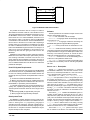
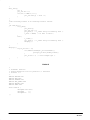
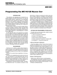
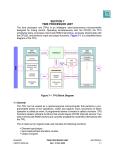
and from the MC68332 to the NEURON C HIP. Figure 1 shows
the various components of the example. The node called
auxnode is a test node for this example and generates a
character string of either “LEFT” or “RIGHT” and passes this
string to the node containing the MC68332 and NEURON CHIP
combination. The sending of these data strings is triggered
by the left and right input buttons on a Gizmo 2 I/O module
from Echelon. The NEURON CHIP in the MC68332/NEURON
CHIP based node then passes this data to the MC68332
where the string is displayed on a terminal attached to the
MC68332’s serial port. Although the example is relatively
MC68332
simple it may be modified to implement an actual user application.
Parallel I/O Overview
The parallel I/O model is one of the standard I/O objects
supplied with a NEURON CHIP. Information on operation of this
I/O object is found in the NEURON CHIP Data Sheet and the
NEURON C Programmer’s Guide. Two versions of this I/O object allow either the connection of two NEURON CHIPS for communication with each other, or the connection of a single
NEURON CHIP to a microcontroller. These two versions are referred to as parallel I/O slave A mode and parallel I/O slave B
mode. For this example parallel I/O mode b is used.
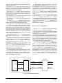
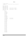
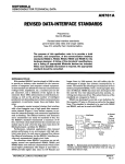
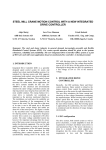
Figure 2 shows the MC68332 to NEURON CHIP hardware
connection. The connection uses all 11 pins of the NEURON
CHIP I/O port for connection to a “host” via an 8–bit data bus,
R/W, chip select and an address pin. By selecting parallel I/O
slave B mode, the address pin, IO_8, allows the NEURON
CHIP to occupy two memory locations in the memory map of
the host processor. These two memory locations are used for
selection of a data transfer memory location and a handshake memory location.
MC143150
NEURON
CHIP
RS232
LONWORKS
NETWORK
332.c
slave.nc
MC68332/NEURON CHIP
BASED NODE
LEFT
RIGHT
LEFT
TEST NODE
RIGHT
auxnode.nc
Figure 1. LONWORKS Parallel I/O to MC68332
MOTOROLA LONWORKS TECHNOLOGY
AN1247
AL–367
MC68332
MC143150
IO_8
CS5
D8 – D15
A0
8
IO_0 – IO_7
IO_10
R/W
VDD
IO_9
VDD
GND
GND
SLAVE B MODE
Figure 2. MC68332 to MC143150 Interface
The parallel I/O interface uses the concept of a token to
allow initiation of transfer of data to or from the NEURON CHIP.
To transfer data between the MC68332 and the NEURON CHIP,
the MC68332 must have the “token”. To transfer data between the NEURON CHIP and the MC68332, the N EURON CHIP
must have the “token”. This token is given to the MC68332
on initialization of the I/O interface. Then the MC68332 transfers the token to the NEURON CHIP either after completing a
transfer of data, or by just passing a null data byte to it. When
the token is obtained the NEURON CHIP will pass this token
back to the MC68332 through the transfer of a null byte, if no
data is to be sent to the MC68332, or by the NEURON CHIP
transferring data and then giving the token back to the
MC68332.
Initialization of the parallel I/O object module and initial establishment of the token ownership is performed by the host
CPU sending a RESYNC command to the NEURON CHIP
which responds with a ACKSYNC command to the host. At
this point the host has the token and the interface is ready for
use. For additional detail refer to the NEURON CHIP data sheet
parallel I/O description.
Host CPU System Requirements
As previously mentioned, this example uses the MC68332
microcontroller; however, any MC68000 family member may
be used. The following hardware and software features are
required by the host processor for implementation of this example.
a) A CPU with a Motorola MC68000 instruction set.
b) Memory map chip select logic for enabling the NEURON
CHIP. This logic may either be contained in the CPU as it is in
the MC68332, or provided by external hardware.
c) A periodic interval timer, PIT, (recommended but not required), “tick”, capable of generating an interrupt to the CPU.
The time period of this timer should be in the range of 20 to
200 ms.
d) Data storage (RAM) of approximately 100 bytes.
e) Driver program size approximately 500 bytes
Development Tools
The M68000 C compiler and linker used to create the object file for this example was release 8.2, available from Intermetrics. Although the “C” programming language is
somewhat universal, data sizes, methods of dealing with interrupt routines, and embedded assembly language may differ with other “C” compilers. Therefore modifications may be
required to adapt to other compilers.
AN1247
AL–368
Software
The files provided for the software example consist of the
following (see Exhibits A thru G).
332.c — main executable code for example.
neuron.h — C language header file describing registers
for the NEURON CHIP.
m332sim.h — C language header file describing the
MC68332 SIM (System Integration Module) registers.
332.lc — memory locate file for the Intermetrics C compiler.
332.bat — DOS batch file containing command lines for
compiling C language source/header files and linking compiler output modules to a single executable object module. The
final entry in the batch file produces “S” records for downloading to a PROM programmer or development system.
slave.nc — NEURON CHIP C file for downloading from a
LONBUILDER to the parallel I/O based node.
aux_node.nc — NEURON CHIP C file for downloading from
a LONBUILDER to an auxiliary node for exercising the parallel
I/O node.
Source 332.c Description
The file 332.c contains the C program of main, functions
for MC68332 initialization, read and write functions to the
NEURON CHIP, and interrupt handlers for a “tick” timer. Following is a brief description of each of these functions.
The function main calls p_init, data_init, master_init and proceeds to look for a keyboard input from
the console. The function kbhit () has been added to the
C standard library and returns true upon detecting that a key
has been hit and is false otherwise. If a key has been hit, the
value of the key is read by getc and added to the end of a
data string of MAX length. Upon receipt of a carriage return
the flag s_data is set true. This will be used later to signal
that there is a string of characters to be transmitted to the
slave NEURON CHIP.
The function p_init initializes the MC68332 system integration module (SIM) for driving the NEURON CHIP with a
chip select line (CS5). Also the interrupt vector for the PIT
(“tick”) timer is initialized and microprocessor interrupts are
enabled. The interrupt vector initialization and enabling of interrupts is done by using a compiler macro labeled vector_init which is defined earlier in the listing. The flag
s_data which is used to indicate if data is ready to be transmitted to the slave NEURON CHIP, is initialized to false.
The function master_init performs the resync operation as outlined in the NEURON CHIP data book. Successful
MOTOROLA LONWORKS TECHNOLOGY
completion of this operation leaves the data transfer token
with the microprocessor.
The function pio_write transmits a string of data to the
NEURON CHIP by enclosing the data in a packet with the
XFER byte and length byte at the beginning of the string and
the EOM value at the end of the string.
The function pio_read reads a string of data from the
parallel I/O interface of the NEURON CHIP. The string is returned in the pio_in function which consists of a length byte
followed by the data bytes.
The function of t_token transfers a null token to the
NEURON CHIP and sets the token flag to false.
The function of tx_hs waits for the handshake line to become low (false).
The function of data_init initializes a test data string in
pio_out. In this example the data string consists of the alphabet. This function is for demonstration purposes.
The function of pit is an interrupt service routine. The
_IH in front of the function name indicates to the compiler
that a return from exception (RTE) instruction should be
placed at the end of the function instead of the normal return
from subroutine (RTS) instruction. This interrupt handler is
triggered by the “tick” timer and either sends a data string
across the MC68332 to NEURON CHIP interface or sends a
null token. The decision to send data or a null token is based
on the current value of the flag s_data.
The last function listed, display, is for debug purposes
and sends the characters from pio_in to the standard output.
Integrating this example into the desired user application
requires rewriting main such that the real user application is
performed. The function p_init must be modified if a different MC683xx processor was to be used. Master_init,
pio_write, pio_read, t_token, tx_hs and pit will
probably not need modification. The routines of data_init
and display are for demonstration purposes only, and
could be removed in a real application program.
Software Options at Compile Time
The following software options may be selected at compile
time by modifying either initial values of variables, or C language define statement values, or lines of source code. For
an understanding of MC68332 register initialization values,
refer to the MC68332 user manual.
The file slave.nc is a NEURON C source file that resides
on the NEURON CHIP connected to the MC68332.
The I/O pin definition for this node selects the I/O object
mode of parallel slave_b which uses all 11 pins as a parallel
interface bus to a host processor.
Following the I/O definition, a structure is defined to contain the length and data fields to be passed from the NEURON
CHIP to the MC68332 and from the MC68332 to the NEURON
CHIP. The next two variables are defined using this structure
definition. The two variables, p_in and p_out, are for an
incoming data string and an outgoing data string.
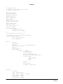
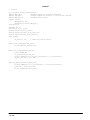
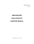
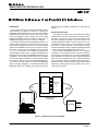
The network variable definitions shown next are nv_
status, nv_data_out and nv_data_in. Network variable nv_status is used as a ready indicator of this node
having completed its resync operation and may not be required in actual application. The network variables
nv_data_in and nv_data_out are of type parallel_in
and are used to move data from the combination
MC68332/NEURON node and the network and network to the
MC68332/NEURON node. The network in this case is node
aux_node. Refer to Figure 3 for a pictorial description of
how their network variables are bound together with the
aux_node.
aux_node
nv_status
RESYNC
READ
Source slave.nc Description
3222_slave
MC68332
WRITE
To set MC68332 exception interrupt levels for the “tick”
timer modify file 332.c, the macro of enable_interrupts,
the MC68000 instruction immediate data field of
“or.w #$0300,d1”. Move the interrupt mask up or down as
required by the interrupt levels that need to be enabled. In
addition the function of p i o _ i n i t, C source line of
mcmsim.picr = 0x041c may be modified as required to
select the interrupt level generated by the periodic interval
timer.
To select the periodic interval timer interrupt time period,
modify function p i o _ i n i t and C source line of
mcsim.pitr = M125SEC. Note that file m68sim.h contains
several predefined values for ease in setting this time period.
To select the location of the NEURON C HIP in the MC683xx
memory map modify function pio_init and the C source
statement of mcsim.csbar5 = 0x0200. Retain the 2K block
size during this modification.
nv_status
blink led
p_in
nv_data_out
nv_data_in
string_out
p_out
nv_data_in
nv_data_out
string_in
Figure 3. Network Variable Binding
MOTOROLA LONWORKS TECHNOLOGY
AN1247
AL–369
The remainder of this source code consists of 4 NEURON
CHIP “when” clauses: when(reset), when(io_out_
ready()), when(io_in_ready()) and nv_update_
occurs()). The task definition of when(reset), common
to almost all NEURON C programs, assigns the ASCII value of
“R” to network variable nv_status. The task definition of
when(io_out_ready()) performs an io_out operation
when the parallel bus is in a state where it can be written to
and the io_out function was previously invoked. The task
definition of when(io_in_ready()) does an io_in
whenever a message arrives on the parallel bus that must be
read. The task definition of when(nv_update_occurs())
processes any incoming information from the network and
triggers an io_out_request.
Source aux_node.nc Description
This NEURON C source program is used for testing the
MC68332/NEURON CHIP combination node. The node function is to send either the character string of LEFT or RIGHT
to the MC68332/NEURON combination node. This node has
the same data structure definition of parallel_in as found
in slave.nc. The network variables of nv_data_in and
nv_data_out are defined with this data type.
Adapting this Example to a Real Application
In a real application, both slave.nc and 332.c must be
modified. The file 332.c must be modified to reflect not only
AN1247
AL–370
the application that the MC68332 is to perform but also the
data to be sent from the MC68332 to the NEURON CHIP across
the parallel interface. In addition, the file slave.nc must be
modified to reflect the data coming into the NEURON CHIP from
the network that is to be passed to the MC68332 across the
parallel interface.
Summary
Application nodes in LONWORKS networks, requiring features beyond that of the NEURON CHIP’s application processor, can easily be designed using an M68xxx host connected
via a parallel interface to a N EURON C HIP. The example
shown, using the MC68332, demonstrated the hardware and
the driver software required to interface an M68000 based
processor architecture to the NEURON C HIP. Modifications for
the C source programs necessary for various processor
chips were discussed and documented. These parallel interface drivers should aid in reducing the program development
cycle — a key feature of LONWORKS control technology and
its ability for short time–to–market.
Disclaimer:
Although this software has been carefully reviewed and is
believed to be reliable, neither Motorola, nor the author assume any liability arising from its use. This software may be
freely used, modified or distributed with user end product(s)
at no cost or obligation to the user.
MOTOROLA LONWORKS TECHNOLOGY
Exhibit A
/*
** Filename: 332.c
** MC68332 to Neuron Parallel I/O demo
** Version 1.0 May 1993
*/
#include <stdio.h>
#include “neuron.h”
#include “m332sim.h”
#define TRUE 0x01
#define FALSE 0x00
#define MAX 30
#pragma separate port
#pragma separate mcsim
struct neuron port;
struct sim mcsim;
char token, s_data, ch;
int error, index;
struct parallel_io{
unsigned char len;
unsigned char data[MAX];
};
struct parallel_io pio_out, pio_in;
/* interrupt vector initialization and enable */
_CASM void vector_init(){
move.1 #_pit,$00000070
move.w #$2300,sr
}
main(){
p_init();
data_init();
display();
/* for debug purposes */
error = master_init();
index = 0;
pio_out.len = 0;
while (TRUE){
if (kbhit() == TRUE){
ch =getc(stdin);
putc(ch,stdout);
pio_out.data[index] = ch;
putc(pio_out.data[index],stdout);
if(ch == 0x0d){
s_data = TRUE;
index = 0;
break;
};
index++;
pio_out.len++;
if(index == MAX) break;
}
}
}
p_init(){
int temp;
temp = mcsim.cspar0;
temp = (temp & 0x0fff) + PORT8;
mcsim.cspar0 = temp;
mcsim.csbar5 = 0x0200;
mcsim.csor5 = CSOPT2;
MOTOROLA LONWORKS TECHNOLOGY
AN1247
AL–371
mcsim.pitr = M125SEC;
mcsim.picr = 0x041c;
vector_init();
/*
s_data = FALSE;
/*
/* init pit to 125 msec interval */
/* init pit to level 4 and vector 28 */
call interrupt init and enable */
no data to send */
}
master_init(){
tx_hs();
port.data = RESYNC;
tx_hs();
port.data = EOM;
tx_hs();
if(port.data == ACKSYN){
error = 0
token = TRUE;
}
else{
error = 1;
}
return(error);
}
pio_write(){
int i;
port.data = XFER;
tx_hs();
port.data = pio_out.len;
tx_hs();
for(i=0; i<(pio_out.len); i++){
port.data = pio_out.data[i];
tx_hs();
}
port.data = EOM;
tx_hs();
token = FALSE;
}
pio_read(){
int index,count;
if(!port.hs){
if(!port.data == XFER){
tx_hs();
pio_in.len = port.data;
count = pio_in.len;
while(index < count){
tx_hs();
pio_in.data[index] = port.data;
index++;
}
}
tx_hs();
token = TRUE;
}
}
t_token(){
port.data = NULL_TOKEN;
tx_hs();
port.data = EOM;
tx_hs();
token = FALSE;
}
tx_hs(){
while(port.hs) ;
AN1247
AL–372
MOTOROLA LONWORKS TECHNOLOGY
}
data_init(){
int i;
pio_out.len = 5;
for(i=0; i<=MAX–1; i++){
pio_out.data[i] = 0x41 + i;
}
}
/*
**the following routine is an interrupt service routine
*/
_IH void pit(){
if(s_data){
pio_write();
pio_out.len = 0;
pio_read(); /* t_token always followed by read */
s_data = FALSE; /* no data to send */
}
else {
t_token();
pio_read(); /* t_token always followed by read */
display();
}
}
display(){
if(pio_in.len != 0){
for(index=0;index<pio_in.len;index++){
putc(pio_in.data[index],stdout);
}
pio_in.len = 0; /* clear length byte */
}
}
Exhibit B
/*
** Filename: neuron.h
** neuron definition file for parallel i/o interface
** Version: 1.0
*/
#define
#define
#define
#define
#define
#define
ACKSYN 0x07
EOM 0x00
HSMASK 0x01
NUL_TOKEN 0x00
RESYNC 0x5a
XFER 0x01
struct neuron {
unsigned char data;
unsigned
:7 ;
unsigned hs :1 ;
} ;
MOTOROLA LONWORKS TECHNOLOGY
AN1247
AL–373
Exhibit C
/*
** Filename: m332sim.h
** definition file for MC68332 Systems Intergration Module (SIM)
** Version: 1.0
*/
#define
#define
#define
#define
CSOPT2
CSOPT3
CSOPT4
PORT8
#define
#define
#define
#define
M500SEC
M125SEC
M62SEC
M32SEC
0x5b30
0x7830
0x7b30
0x2000
0x0108
0x0102
0x0101
0x00ff
struct sim{
int picr;
int pitr;
int swsr;
int unused_1;
int tstmsra;
int tstmsrb;
int tstsca;
int tstrc;
int creg;
int dreg;
int unused_2;
int unused_3;
int cspdr;
int unused_4;
int unused_5;
int unused_6;
int unused_7;
int cspar0;
int cspar1;
int csbarbt;
int csorbt;
int csbar0;
int csor0;
int csbar1;
int csor1;
int csbar2;
int csor2;
int csbar3;
int csor3;
int csbar4;
int csor4;
int csbar5;
int csor5;
int csbar6;
int csor6;
int csbar7;
int csor7;
int csbar8;
int csor8;
int csbar9;
int csor9;
int csbar10;
int csor10;
} ;
AN1247
AL–374
/* value
/* value
/* value
/* value
for
for
for
for
pitr
pitr
pitr
pitr
of 500 msec */
of 125 msec */
of 62 msec */
of 32 msec */
/* not in book */
/* not in book */
/* not in book */
MOTOROLA LONWORKS TECHNOLOGY
Exhibit D
LOCATE
LOCATE
LOCATE
LOCATE
LOCATE
(S_mcsim : #FFFA22) ;
(S_port : #20000) ;
(init : #5000) ;
(code : AFTER #5000) ;
(data : #4f00) ;
Exhibit E
rem 332.bat
rem
c68332 332.c –p –l –ia –i –err error1
1link 332.ol _L \itools\rtlibs\lib332\lib\lib332 –c 332.lc –o –err error
form 332.ab –ec usep isep
MOTOROLA LONWORKS TECHNOLOGY
AN1247
AL–375
Exhibit F
// slave.nc
IO_0 parallel slave_b parallel_bus;
#define MAX_IN 21
#define OUT_LEN 7
#define MAX_OUT 13
//maximum length of input data expected
//output length can be equal to or less than the max
//maximum array length
typedef struct {
unsigned int len;
unsigned int buffer [MAX_IN];
}parallel_in;
unsigned int i;
parallel_in p_in, p_out;
network output char nv_status;
network output parallel_in nv_data_out;
network input parallel_in nv_data_in;
when (reset){
nv_status = ’R’;
// indicate slave in resync
}
when(io_out_ready(parallel_bus)){
io_out(parallel_bus,&p_out);
}
when(io_in_ready(parallel_bus)){
p_in.len=MAX_IN;
io_in(parallel_bus,&p_in);
for(i=0;i<MAX_IN;i++) nv_data_out.buffer[i] = p_in.buffer[i];
nv_data_out.len = p_in.len;
}
when (nv_update_occurs(nv_data_in)){
for(i=0;i<MAX_IN;i++) p_out.buffer[i] = nv_data_in.buffer[i];
p_out.len = nv_data_in.len;
io_out_request(parallel_bus);
}
AN1247
AL–376
MOTOROLA LONWORKS TECHNOLOGY
Exhibit G
// aux_node.nc
IO_1 output oneshot clock(7) led;
IO_3 input bit right_switch;
IO_7 input bit left_switch;
#define MAX_IN 20
#define OUT_LEN 7
typedef struct {
unsigned int len;
unsigned int buffer[MAX_IN];
}parallel_in;
network input char nv_status_in;
network input parallel_in nv_data_in;
network output parallel_in nv_data_out;
unsigned int i;
parallel_in string_in, string_in_aux, string_out;
when(nv_update_occurs(nv_status_in)){
io_out(led,10000);
}
when(nv_update_occurs(nv_data_in)){
string_out.len = nv_data_in.len;
for(i=0; i<MAX_IN; i++)string_out.buffer[i] = nv_data_in.buffer[i];
io_out(led,10000);
}
when(io_changes(right_switch) to 0){
nv_data_out.len = string_in.len;
for(i=0; i<MAX_IN; i++)nv_data_out.buffer[i] = string_in.buffer[i];
io_out (led,10000);
}
when(io_changes(left_switch) to 0){
nv_data_out.len = string_in_aux.len;
for(i=0; i<MAX_IN; i++)nv_data_out.buffer[i] = string_in_aux.buffer[i];
io_out(led,10000);
}
when(wink)
when(reset){
io_out(led,10000);
string_in.len = 6;
memcpy(string_in.buffer,“RIGHT\n”,6);
string_in_aux.len = 5;
memcpy(string_in_aux.buffer,“LEFT\n”,5);
}
MOTOROLA LONWORKS TECHNOLOGY
AN1247
AL–377