1
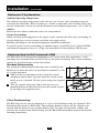
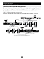
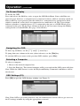
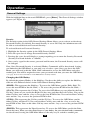
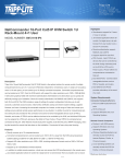
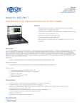
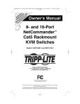
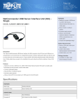
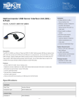
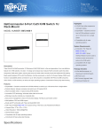
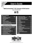
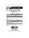
ce TY N chanuct! N O I a d RA ATy for e pro nty R R a it rra A W ISTe todipp L /wa r m n G T o li REer on REE lite.c F pp st gi in a .tri Re w ww to w Owner’s Manual 16-Port NetCommander™ Cat5 Rackmount Console KVM Switch Model #: B070-016-19 Tripp Lite World Headquarters 1111 W. 35th Street, Chicago, IL 60609 USA (773) 869-1234, www.tripplite.com Note: Follow these instructions and operating procedures to ensure correct performance and to prevent damage to this unit or to its connected devices. Copyright © 2007 Tripp Lite. All rights reserved. All trademarks are the property of their respective owners. The policy of Tripp Lite is one of continuous improvement. Specifications are subject to change without notice. Table of Contents Features.. ......................................................................................... p. 3 System Components….................................................................... p. 3 Compatibility…............................................................................... p. 3 Configuration…............................................................................... p. 4 Front View................................................................................ p. 4 Rear View................................................................................. p. 5 Installation……............................................................................... p. 6 Pre-Installation Guidelines....................................................... p. 6 Connecting the NetCommander KVM System…................... p. 6 NetCommander Server Interface Units.................................p. 6-7 Connecting the Power Supply.................................................. p. 7 Resetting the NetCommander KVM System........................... p. 7 Rackmount Considerations...................................................... p. 8 Rackmounting the NetCommander KVM System ................. p. 8 Cascading NetCommander KVM Switches............................ p. 9 Connecting the B050-000...................................................... p. 10 Operation....................................................................................... p. 10 Basic Operation...................................................................... p. 10 Keyboard Hotkeys.................................................................. p. 10 On-Screen Display................................................................. p. 11 Navigating the OSD............................................................... p. 11 Selecting a Computer............................................................. p. 11 OSD Settings (F2).................................................................. p. 11 General Settings................................................................p. 12-13 F7 Defaults............................................................................. p. 14 Port Settings........................................................................... p. 14 Time Settings......................................................................... p. 15 Security.................................................................................. p. 16 Users....................................................................................... p. 17 OSD Help Window (F1)........................................................ p. 17 Scanning Computers (F4)...................................................... p. 17 Tuning (F5)............................................................................ p. 18 Moving the Label (F6)........................................................... p. 18 System Requirements for Firmware Upgrade............................... p. 18 Software ....................................................................................... p. 18 Upgrading the KVM Firmware.............................................. p. 18 Connecting RS232 Serial Cable............................................ p. 19 Installing the Software........................................................... p. 19 Starting and Configuring the KVM Update......................p. 19-20 Verifying the Version Numbers.........................................p. 20-21 Obtaining New Firmware....................................................... p. 21 Updating the Firmware.......................................................... p. 21 Reset....................................................................................... p. 22 Troubleshooting............................................................................. p. 22 USB/SUN Combo Keys................................................................ p. 23 Specifications................................................................................. p. 23 1-Year Limited Warranty/Warranty Registration........................... p. 24 Español ....................................................................................... p. 25 Françis ....................................................................................... p. 52 2 Features • 16-Port KVM Switch with built-in 19" LCD display, keyboard and touch pad • Access and control multiple multi-platform computers from a single console • Hot-swappable: disconnect and reconnect USB computers without rebooting • Auto-scan: with variable time interval • Compact design: 1U rack mountable • Easy port selection using (1) On Screen Display (OSD), (2) keyboard hotkeys key sequences • Expandable: control up to 256 computers by adding additional KVM switches • Simple cable management: use standard Cat5e patch cord (maximum distance 100 ft) to connect to each computer • Multi-platform: supports PS/2 and USB computers/server • Optional Tripp Lite B050-000 IP Remote Access Unit to access the B070-016-19 via LAN, WAN or the Internet System Components The NetCommander Cat5 KVM system consists of: • NetCommander Rackmount Cat5 Console KVM Switch (Model B070-016-19) • NetCommander Cascadeable Rackmount Cat5 KVM Switch (Model B072-016-1 or B072-008-1)* • NetCommander Server Interface Unit - PS/2 (Model B078-101-PS2)* - USB (Model B078-101-USB)* • Cat5e Cables (Model N001-Series, N002-Series or N105-Series)* • RS-232 Serial Firmware Upgrade Cable * Sold separately Note: The B070-016-19 comes with a Jumper Cable connecting the Integrated Console Ports and the KVM Console Ports. Do not remove the Jumper Cable unless you are installing a Tripp Lite B050-000 IP Remote Access Unit. See B050-000 Installation Procedure for details. Compatibility The KVM is compatible with: • PS/2 and USB computers/servers • VGA, SVGA, or XGA monitors • DOS, Windows, LINUX, UNIX, Mac and all other major operating systems • 1600 x 1200 @ 75Hz (for built-in monitor) 3 Configuration Front View 6 10 7 12 1 2 3 4 5 8 Figure 2 NetCommander KVM Buttons 13 11 9 Figure 1 NetCommander KVM front panel 1 Auto: When the LCD Menu is closed, pressing the AUTO button will perform an Auto Adjust on the monitor screen. When the LCD Menu is open, pressing the AUTO button will bring you back to the previous screen/selection. If the LCD Menu cannot go back any further, the AUTO button will close down the menu. 2 Menu: When the LCD Menu is closed, pressing the MENU button will open it. When the LCD Menu is open, pressing the MENU button will select a highlighted option. 3 On/Off Button: Pressing this button will turn the monitor screen on or off. 4 < : When the LCD Menu is open, pressing the < button will move the highlight bar to the left. When modifying a selected option, pressing the < button will decrease the option. 5 > : When the LCD Menu is open, pressing the > button will move the highlight bar to the right. When modifying a selected option, pressing the > button will increase the option. 6 Handle: Pull to slide the module out; push to slide the module in. 7 19" LCD Monitor: After sliding the module out, flip up the cover to access the LCD monitor, keyboard and touch pad. 8 Keyboard 9 Slide Release: Mechanism to lock the drawer closed when the console is not in use. Prevents it from accidentally sliding open. To slide the console out, you must first release it by moving the tab sideways. 10 Rackmounting Brackets: There are rackmount brackets to secure the chassis to a system rack located at each corner of the unit. 11 2-Button Touch Pad: Left button is left click, right is right click. Run your finger up or down the far right side of the touchpad to scroll up and down a screen. 12 LCD Display Controls: The LCD OSD controls located here control the position and picture settings of the LCD display. See LCD OSD configuration for details. 13 Railway Release Tabs: When the drawer is completely pulled out to the end, the railway system will lock. Push the release tabs on both sides to release the drawer so that it can be pushed back in. 4 Configuration (continued) Rear View 1 2 3 5 4 6 Figure 3 NetCommander KVM rear panel 1 Power Socket: The power cord plugs in here from the AC power source. 2 On/Off Switch: Turns the KVM Switch on and off. 3 Firmware Upgrade Port: Plug included firmware upgrade cable into this port to download firmware upgrade data. 4 CPU Port Section: Plug the Cat5e cables from each PC or server into these ports. 5 KVM Console Ports* 6 Integrated Console Ports* * The B070-016-19 comes with a Jumper Cable connecting the 'Integrated Console Ports' and the 'KVM Console Ports.' Do not remove the Jumper Cable unless you are installing a Tripp Lite B050-000 IP Remote Access Unit. See B050-000 Installation Procedure for details. 5 Installation Pre-Installation Guidelines • Switch off all computers* • Ensure that the cables are not close to any sources of electrical noise interference such as fluorescent lights, HVAC systems or motors • Ensure that the distance between any computer and the KVM switch does not exceed 100 ft. * PS/2 computers need to have the Keyboard and Mouse connectors installed before they are turned on. If you plug the Keyboard and Mouse connectors into an active PS/2 computer, it may not recognize them, causing them not to work. Connecting the NetCommander KVM System Connect each computer to the B070-016-19 using a Tripp Lite B078-101-PS2* or B078-101-USB* Server Interface Unit (SIU) and a Cat5e patch cable. (For best results, use a Tripp Lite N105-Series cable*). * Sold separately. NetCommander Server Interface Unit (SIU) The NetCommander Server Interface Unit The Server Interface Unit gets its power from the connected computer. In the case of the NetCommander PS/2 Server Interface Unit (B078-101-PS2), the power is drawn from the keyboard port. In the case of the NetCommander USB Server Interface Unit (B078-101USB), the power is drawn from the USB port. When connected and receiving power, the green LED on the SIU will illuminate. When connected to the active port on the KVM, the orange LED will illuminate. Connecting a NetCommander PS/2 Server Interface Unit (Model # B078-101-PS2) 1. Shut down the computer being connected to the B078-101-PS2 (SIU) 2. Connect the B078-101-PS2 VGA connector to the computers VGA port 3. Connect the B078-101-PS2 PS/2 Keyboard connector to the computers PS/2 Keyboard port 4. Connect the B078-101-PS2 PS/2 Mouse connector to the computers PS/2 Mouse port 5. Connect one end of the Cat5 patch cable to the RJ45 port on the B078-101-PS2* 6. Connect the other end of the Cat5 patch cable to the desired RJ45 port on the B070-016-19 Console KVM.* The green LED will illuminate when connected and receiving power. 7. Repeat these steps for each additional PS/2 computer/server you are connecting to the B070-016-19 Console KVM * Cat5 cable should be no longer than 100ft. (10m). Up to 100 ft SIU = Server Interface Unit Figure 4 NetCommander PS/2 Server Interface Unit 6 Installation (continued) Connecting a NetCommander USB Server Interface Unit (Model # B078-101-USB) 1. Connect the B078-101-USB VGA connector to the computers VGA port 2. Connect the B078-101-USB USB connector to the computers USB port 3. Connect one end of the Cat5 patch cable to the RJ45 port on the B078-101-USB* 4. Connect the other end of the Cat5 patch cable to the desired RJ45 port on the B070-016-19 Console KVM.* The green LED will illuminate when the SIU is connected and receiving power. 5. Repeat these steps for each additional USB computer/server you are connecting to the B070-016-19 Console KVM * Cat5 cable should be no longer than 100 ft. Up to 100 ft SIU = Server Interface Unit Figure 5 NetCommander USB Server Interface Unit Connecting the Power Supply 1. Plug in the KVM using only the power cord supplied with the unit. 2. Switch ON the B070-016-19 console KVM. Resetting the KVM Switch To reset the KVM switch, turn the unit off and then back on using the power switch on the back. The Server Interface Units are unaffected by this reset. 7 Installation (continued) Rackmount Considerations Ambient Operating Temperature The ambient operating temperature in the rack may be an issue and is dependent upon the rack load and ventilation. When installing in a closed or multi-unit rack assembly, make sure that the temperature will not exceed the maximum rated ambient temperature. (32º to 104º F) Airflow Ensure that the airflow within the rack is not compromised. Circuit Overloading When connecting the equipment to the supply circuit, consider the effect that overloading of circuits might have on over-current protection and supply wiring. Reliable grounding of rack-mounted equipment should be maintained. To protect against circuit overloading you should connect your B070-016-19 Console KVM and attached computers/servers to a Tripp Lite SmartPro® or SmartOnline® UPS System. Rackmounting the NetCommander KVM The B070-016-19 is designed for mounting in a 1U rack system. For convenience, a rack mounting kit is included with your B070-016-19 for quick installation. The various mounting options are explained in the sections that follow. Standard Rackmounting The standard rackmounting brackets that come attached to the B070-016-19 allow the unit to be installed in standard 1U racks by a single individual. 1 Slide out the rear mounting brackets from the console 1 and mount both brackets (separate from the console) to the inside rear of a standard 1U rack system using user-supplied screws. 2 Take the console and gently slide it into the two rearmounted brackets in the rack and secure the console in place 2 by inserting user-supplied screws. 2-Post Rackmounting The B070-016-19 can also be mounted in a 2-post rack installation using the optional 2-Post Rackmount Kit (model #: B019-000). The mounting hardware allows for the console to be opened with the drawer in any position. Heavy-duty 14-gauge steel provides stability and prevents the console frame from twisting. See the B019-000 instructional manual for detailed mounting instructions. 8 Installation (continued) Cascading NetCommander KVM Switches To cascade two or more NetCommander KVM switches, follow the instructions below. Connect up to 256 computers* using any combination of B072-008-1 and B072-016-1 KVM switches. You can only cascade 1 extra level of KVM switches onto the B070-016-19 Console KVM. * When all 16 ports have a B072-016-1 cascaded from them. Setting the different OSD display hotkeys for cascaded KVMs is explained on page 14. Model: B070-016-19 Model: B072-008-1 or B072-016-1 Model: B072-008-1 or B072-016-1 SIU = Server Interface Unit Figure 6 Cascading NetCommander KVM switches 9 Installation (continued) Connecting a B050-000 IP Remote Access Unit to the B070-016-19 1. Disconnect the Jumper Cable Console Connectors that are plugged into the KVM Console Ports. 2. Plug the end of the Jumper Cable you just disconnected into the ports on the B050-000 cable marked Local Console Ports. 3. Connect the PS/2 and VGA cables marked 'To server or KVM' to the KVM Console Ports on the B070-016-19. Note: The PS/2 Cables and VGA Cable are on separate cables that come included with the B050-000 IP Remote Access Unit. 4. For further setup instructions for the B050-000 IP Remote Access Unit refer to the Owner's Manual that comes with the unit. Figure 7 Connecting a B050-000 IP Remote Access Unit to the B070-016-19 Operation Basic Operation Switch between the connected computers using any of the following methods: • The OSD (On Screen Display) • Keyboard hotkey commands The OSD is also used to adjust various settings. A confirmation label at the top of your monitor screen identifies which computer is currently selected. Keyboard Hotkeys To switch to the next computer, press and release the [Shift] key, then press the [+] key. To switch to the previous computer, press and release the [Shift] key, then press the [-] key. Note! You can use the [+] key of the alphanumeric section or of the numeric keypad on a US English keyboard. With a Non-US English keyboard, use the [+] key of the numeric keypad only. 10 Operation (continued) On-Screen Display To invoke the OSD: Press and release the Shift key twice to open the OSD Main Menu. Lines with Blue text represent ports that have a computer/server connected to them, which is currently turned on. Lines with Gray text represent ports that either has a computer/server connected to them, which is turned off; or they have no computer/server connected at all. The Type column indicates whether a computer/server (C) is connected to the port or a KVM Switch (S) is connected to the port. For the Type column to display S, the user must change the Hotkey setting for the cascaded KVM. (See page 14 for details.) Figure 8 The OSD Main Window Navigating the OSD To move up and down, use the [ ] and [ ] arrow keys. To jump from one column to the next (when relevant), use the [Tab] key. To exit the OSD or to return to the previous OSD window, press [Esc]. Selecting a Computer To select a computer: 1. Move to the desired computer line. 2. Press the Enter key. The selected computer will be accessed and the OSD screen will close. Note: While the OSD Screen is active the Keyboard Hotkey Commands and Mouse will be deactivated. OSD Settings (F2) Press [F2] to open the OSD Settings window (see Figure 9). Figure 9 The Settings Window Note: If the OSD is password protected, only the Administrator will be able to get access to the F2 settings window by using the appropriate password. 11 Operation (continued) General Settings With the highlight line on the word GENERAL, press [Enter]. The General Settings window appears (see Figure 10). Security Figure 10 The General Settings window The Security option in the OSD General Settings Menu allows you to activate or deactivate Password Security. By default, Password Security is set to Off. Only the Administrator will be able to activate/deactivate Password Security. To activate/deactivate Password Security: 1. Highlight the Security option in the OSD General Settings Menu 2. Press the space bar to change Password Security On/Off 3. Pressing the space bar will display a prompt requiring you to enter the Security Password. (Security Password defaults as 'Admin') 4. Once you've typed in the correct password and hit enter, the Password Security status will be changed Note: Once Password Security is activated, Hotkey Commands will be deactivated, leaving you limited to the OSD Menu as your only way to select a port. Once you leave the OSD Menu, you will need to hit the 'Shift, Shift' command to access the OSD Menu and select another port. You will be required to enter your password each time you enter the OSD Menu. * See page 16-17 for more information on the B070-016-19 Security features. Changing the OSD Hotkey By default the primary Hotkey is the Shift key. You have the ability to replace the Shift key with one of 4 different choices in the OSD General Settings Menu. (SH-SH): This represents the Shift key. To access the OSD Menu you hit 'Shift, Shift.' To access the next KVM in line hit 'Shift, +.' To access the previous KVM in line hit 'Shift, -.' (CL-CL): This represents the Ctrl key. To access the OSD Menu you can either hit the Left Ctrl key 2 times or you can hit the Right Ctrl key once and then the Left Ctrl key. You can hit either Ctrl key once and the + key to access the next KVM in line. You can hit either Ctrl key once and the - key to access the previous KVM in line. (CLF11): This represents the Ctrl key and the F11 key. To access the OSD Menu you hit either Ctrl key and then F11. You can hit either Ctrl key once and the + key to access the next KVM in line. You can hit either Ctrl key once and the - key to access the previous KVM in line. (PRSCR): This represents the Print Screen key. To access the OSD Menu you hit the Print Screen key once. When you select Print Screen as your hotkey, the port selection hotkey commands are deactivated, leaving the OSD Main Menu as the only way to switch to another port. 12 Operation (continued) When you have cascaded KVM switches, a lower level Switch must have a different OSD display hotkey than a higher level switch. To change the top-level switch hotkey: 1. Highlight the Hotkey option in the OSD General Settings Menu 2. Press the space bar to toggle through the various options 3. When you've selected the desired hotkey, simply exit the OSD. Hitting the Enter key is not required to activate your selection To change a lower level hotkey: 1. Connect a keyboard and monitor to the lower level switch 2. Hit Shift, Shift to open the OSD Menu 3. Hit F2 to get to the General Settings Menu, and highlight the Hotkey option 4. Press the Space Bar to toggle through the various hotkeys 5. When you've selected the desired hotkey, simply exit the OSD Menu. Hitting the Enter key is not required to activate your selection 6. Follow the instructions on page 14 to update the Port Settings menu in the top-level KVMs OSD to reflect the lower-level KVMs new hotkey Note: When Password Security is activated, all port selection hotkey commands are deactivated, leaving the OSD Main Menu as the only way to switch to another port. Auto Skip The Auto Skip option allows you to choose whether you want Inactive ports to be selectable or not. If the Auto Skip option is turned on, Inactive ports will not be accessible via the OSD Main Menu or the Port Selection Hotkey Commands. If the Auto Skip option is turned on, you will be able to access Inactive ports using either the OSD Main Menu or the Port Selection Hotkey Commands. To change the Auto Skip setting: 1. Highlight the Auto Skip option in the OSD General Settings Menu 2. Press the space bar to turn the Auto Skip option On/Off Serial Port The Serial port is used for the Firmware upgrade. Serial port On means the program can be used. To change the Serial port setting: 1. Highlight the Serial Port option in the OSD General Settings Menu. 2. Press the space bar to turn the Serial Port option On/Off. Changing the Keyboard Language The keyboard is preset to US English. It can be changed to French (FR) or German (DE) by doing the following: 1. Highlight the Keyboard language option in the OSD General Settings Menu 2. Press the space bar to toggle through the various options. 3. When you've selected the desired language, simply exit the OSD. Hitting the Enter key is not required to activate your selection 13 Operation (continued) Editing the Switch Name The KVM Switch Name appears at the bottom of the OSD General Settings Menu, and can be changed to whatever you want. When cascading KVMs onto the B070-016-19, it is necessary to access the cascaded KVMs OSD using it's own hotkey. Giving cascaded KVMs OSDs unique names makes it easier when accessing them to verify which switches OSD you are accessing. To change this name simply type over the existing letters. You can create a name up to 18 characters in length, with spaces counting as characters. Reset OSD General Settings Menu to Defaults (F7) When in the OSD General Settings Menu, you can reset all of the options to the original default settings, erasing any changes you have made. If you have changed the Security Passwords, they will be reset to their defaults as well. Ports Settings In the OSD Settings Menu (Access by pressing F2 in the OSD Main Menu), highlight the Ports option and press enter. Editing the Computer Name Figure 11 Ports Settings window By default each port is named 'Computer 01, Computer 02, etc.' To personalize these names for each computer, highlight the desired port and type directly over the text that's already there. Each name has a maximum of 15 characters, each space counting as one character. To delete a character, simply highlight it and press the space bar. Editing the Keyboard (KB) Column The KVM operates with Windows, Linux, HP UX, Alpha UNIX, SGI, DOS, Novell, MAC, USB or Open VMS. By default the Keyboard Mode is set to PS for Intel Based computers. For a different keyboard mode, highlight the desired port and press the Tab key to highlight the KB column. Press the space bar to toggle through the following options: U1 - HP UX U2 - Alpha UNIX, SGI or Open VMS U3 - IBM AIX Adding/Changing a Hotkey (HKEY) for Cascaded KVM Switches When a KVM Switch is cascaded to the B070-016-19 Console KVM, it is necessary to select a hotkey in this field. This is required so the B070-016-19 knows that when the Cascaded KVM Port is selected and you hit the selected OSD Hotkey Command, it is supposed to pull up the OSD Main Menu for that KVM switch. If a Hotkey is not selected for a cascaded KVM, you will not be able to access the cascaded KVMs OSD. For connected computers/ servers this field should have “NO” selected. 14 Operation (continued) To add/change a hotkey: 1. Highlight the desired port and press the Tab key until the HKEY column is highlighted 2. Press the space bar to toggle through the various choices 3. When you've selected the desired hotkey, simply exit the OSD. Hitting the Enter key is not required to activate your selection Time Settings In the Settings window navigate to the Time line and press [Enter]. The Time settings window appears (see Figure 12). Figure 12 Time settings window SCN - Sets the amount of time spent on the selected computer when Auto Scanning. LBL - Sets the amount of time the OSD label that shows which computer is currently accessed is displayed. T/O - When password protection is activated, you can automatically disable the Keyboard, Mouse and Monitor after a set amount of inactive time, requiring a password to be entered to regain access to the KVM switch. When Timed Out, press the 'Shift, Shift' OSD Hotkey Command to pull up the password prompt, which will take you back to the OSD Main Menu once you enter your password. To set the above periods: 1. On the desired line press Tab to jump to the desired column. 2. Place the cursor over one of the 3 digits and type a new number. Enter a leading zero where necessary. For example, type 030 for 30 seconds. Enter 999 in the LBL column to have the label displayed continuously. Enter 000 if you do not want the label to appear. Enter 999 in the T/O column to disable the Timeout function. Enter 000 if you want the Timeout function to work immediately.* * This will literally cause the Timeout function to begin immediately when the computer port is selected. This will essentially freeze access to the KVM, not allowing the user enough time to hit the OSD Hotkey Command to pull up the password prompt. It is recommended that you always keep the T/O set to 5 seconds or higher. If you set the T/O at 000 and get locked out of the KVM, turn the B070-016-19 Console KVM Off and then back On. This will reset the KVM, leaving a blank screen on the monitor. Hit the 'Shift, Shift' OSD Hotkey Command to pull up the password prompt. Once you type in your password, you will again have access to the OSD Main Menu. Enter 999 in the SCN column to display the screen for 999 seconds. Enter 000 to skip the computer screen. 15 Operation (continued) Security Figure 13 The Security settings window The OSD offers an advanced password security system made up of three different security levels, each having its own access rights. Administrator (Status A): The Administrator has access to all features of the KVM, allowing them to Set/Modify all Passwords and Security Profiles, gain full access to any computer connected to the KVM and usage of all OSD features. Supervisor (Status S): The supervisor has full access to all computers connected to the KVM and can use the Auto Scan (F4), Tuning (F5) and Confirmation Label Moving (F6) functions in the OSD. The Supervisor can not change any of the OSD Settings or Security Settings. User (Status U): There can be up to 6 Users set up by the Administrator for access to the KVM. Users are able to use the OSD Main Menu to access a connected computer and can use the Auto Scan (F4), Tuning (F5) and Confirmation Label Moving (F6) functions in the OSD. Users do not have the ability to use any other OSD features. The Administrator will choose which computers they have access to and which they do not. There are 3 types of access the Administrator can give a User: Y - This gives the user full access to a connected computer. V - This gives the user view only access to a computer. Keyboard and mouse functionality are not available. N - This means a user is not allowed to access a connected computer. If the User attempts to access a computer they are not allowed to, a blank screen will appear. Security Settings When Password Security is set to on, only the administrator can change the Security Settings of the KVM switch. Security Settings 1. Highlight the Security option in the OSD Settings Menu and hit the Enter key. 2. To change the name of the Administrator, Supervisor or User, highlight the desired name and simply type over what's already there. Any letters left over can be deleted by pressing the space bar. 3. To change the password, hit the Tab key to highlight the Password column of the desired person and type in the new password. 4. The last column (T) refers to the level of access; Administrator (A), Supervisor (S) or User (U). You can change these if you want, but there can only be 1 Administrator, 1 Supervisor and 6 Users. 16 Operation (continued) User Settings 1. Highlight the Users option in the OSD Settings Menu and hit the Enter key. 2. The Users will be represented in the 6 columns on the right side of the screen. To change the access for a given computer, highlight the desired computer and hit the Tab key until the desired user is highlighted. 3. Press the space bar to toggle between the 3 access options (Y, V or N). See page 16 for details on these 3 options. Figure 14 The Users Settings Window OSD HELP Window (F1) To access the HELP window press [F1]. The HELP window is displayed (see Figure 15). Figure 15 The HELP window Please note! All the functions in the Help window are performed from the OSD Main Menu. The Help window only serves as a reminder of the OSD function keys. Scanning Computers (F4) The amount of time spent on a computer when Auto Scanning is adjustable. See page 15 for details. To activate scanning: 1. Press the [Shift] key twice to activate the OSD. 2. Press the [F4] key. Each active computer will be displayed in sequence. A Scan label appears in the top left corner. To deactivate scanning: Press [F4]. 17 Operation (continued) Tuning (F5) You can tune the image of any remote computer screen. To adjust the screen image: 1. In the OSD Main Menu highlight the computer you want to adjust. 2. Press the [F5] key. The screen image of the selected computer is displayed, along with the Image Tuning label. 3. Adjust the image by using the Right and Left Arrow keys. 4. When the image is satisfactory, press [Esc]. Note! Distance affects picture quality. The further away a remote computer is from the KVM, the lower the image quality and the more tuning needed. Therefore put any higher resolution computers closer to the KVM. Moving the Label (F6) You can position the OSD label anywhere on the screen. To position the label from the Main window: 1. Move to the desired computer using the Up and Down Arrow keys. 2. Press the [F6] key. The selected screen image and Identification label are displayed. 3. Use the arrow keys to move the label to the desired position. 4. Press [Esc] to save and exit. System Requirements for Firmware Upgrade • Pentium 166 or higher with 16MB RAM and 10MB free Hard Drive space • Free Serial port • Windows 2000 and later • To update the firmware the KVM system must be connected and switched on. Software Upgrading the KVM Firmware With the NetCommander KVM Update software program you can upgrade the firmware for the: • OSD • B070-016-19 Console KVM • Server Interface Units KVM Update enables you to add new features and take advantage of product improvements in a quick and efficient manner. 18 Software (continued) Connecting the RS-232 Serial Firmware Upgrade Cable To run the firmware upgrade software, you must first connect the RS-232 Serial Firmware Upgrade cable between the B070-016-19 and a separate computer (One not connected to the KVM switch) containing the firmware upgrade software. Note: Each cascaded KVM Switch must be updated separately. When you're done updating the first KVM Switch, attach the RS-232 Serial Firmware Upgrade cable between each cascaded KVM and the Update Computer. For the firmware upgrade to take place, the Serial Port option in the OSD General Settings Menu must be set to On. If it is set to Off, you will not be able to perform a firmware upgrade. When password security is turned on, the only person who can turn the Serial Port option On and Off is the administrator. Installing the Software To install the KVM Switch Update software: 1. Download KVM update software from www.tripplite.com 2. Run the software. If there is no firmware upgrade currently available, there will be nothing posted on www.tripplite.com Starting and Configuring the KVM Update 1. Start the KVM Update software. The KVM Update window appears (see Figure 16). KVM Switch SIUs Status box Figure 16 The KVM Switch Update window The table below explains the functions of the buttons and boxes in the KVM Switch Update window. 19 Software (continued) 2. From the Options menu choose Com Port. The Com Port box appears (see Figure 17). Figure 17 The Com Option box 3. Select the COM Port of the Upgrade Computer that you connected the RS232 Serial Firmware Upgrade Cable to. If it is not connected to the COM Port you've chosen, the Firmware Upgrade will fail. Verifying the Version Numbers Before upgrading your firmware, verify that you are not already using the most current firmware. To do this, obtain the firmware version number using the steps below, and compare it with the firmware version number on www.tripplite.com. You'll also need to verify the hardware version number of your KVM Switch and SIU(s), in the case that the firmware upgrade is not compatible with your current unit. Compatible hardware version numbers will also be posted on www.tripplite.com. In the event that your KVM Switch or SIU(s) are not compatible with the firmware upgrade, you will not be able to install the firmware upgrade unless you buy a new unit that is compatible with the upgrade. * If there is no firmware upgrade currently available, there will be nothing posted on www.tripplite.com The OSD version number To verify the OSD version number: 1. Open the KVM Switch Update program. 2. In the Switch Unit box, check the NetCommander Cat5 KVM Switch OSD option. See Figure 16. 3. Click . The version number appears in the Switch box. The H/W Version button is grayed out, as there is no hardware relevant to the OSD. The KVM Manager version number To verify the KVM version number: 1. Open the KVM Switch Update program. 2. In the Switch Unit box, check the NetCommander Cat5 KVM Switch Manager option. 3. Click . The firmware version number appears in the Switch Unit box. 4. Click . The hardware version number appears in the Switch Unit box. 20 Software (continued) Verifying the Server Interface Unit's version number Before you can check a Server Interface Unit, you must uncheck the Switch Unit box options. To verify the Server Interface Unit version number: 1. Open the KVM Switch Update program. 2. Check one or more or all of the Server Interface Units. 3. Click Unit number. . The firmware version number appears after the Server Interface 4. Click Unit number. . The hardware version number appears after the Server Interface When “Not responding” appears, no computer is connected, or it is switched off. Obtaining New Firmware Download the latest firmware for your system from www.tripplite.com Updating the Firmware Warning! Never switch off any computer connected to the KVM system during the Firmware Upgrade process. Figure 18 The Open box 1. Download the latest firmware for your B070-016-19 KVM Switch from www.tripplite.com 2. Using the Update Computer, open up the Firmware Upgrade Software 3. In the KVM Switch Update Window, select the KVM Switch, KVM Switch OSD or SIU(s) you would like to upgrade 4. From the File Menu, choose Open to open up the firmware upgrade file you down loaded from www.tripplite.com and open the file 5. Click the Start button to begin the update. When finished, the firmware version number will appear next to the unit you just updated 6. Check to make sure the Firmware Version Number is correct by following the steps on page 20-21. If it does not show up as the most current Firmware Version Number, start the upgrade over again. 21 Software (continued) Firmware Update generates one log file per session that displays a chronological list of actions. You can read the log file in any ASCII text editor. The log file is located in the Windows directory. Resetting the KVM Switch or SIU(s) In the event the KVM Switch or SIU(s) freezes during firmware upgrade or the KVM Console Mouse/Keyboard are not working properly, you can reset the unit using the Upgrade computer. This will not affect any of the settings on the KVM Switch or SIU. Follow the instructions below to reset your KVM Switch or SIU. 1. Using the Upgrade Computer, select the KVM Switch or SIU(s) you wish to reset in the firmware upgrade software window. 2. In the Options menu, select the Advanced/Reset option. This will reset the selected KVM Switch or SIU(s). You should now be able to use your KVM Switch or SIU(s). Troubleshooting Note: Disconnect device from AC mains before service operation! When using Firmware Update software you may at times get a Communication Error message. If a Communication Error message does appear during the update procedure, do the following: 1. Ensure that the RS232 Serial cable's RS232 connector is connected to the Switch's Communication port. 2. Ensure that the RS232 Serial cable's DB9F connector is connected to the DB9M Serial port on the CPU's rear panel. 3. Restart the download process. Electricity failure If the electricity fails during an update to the KVM firmware, do the following: 1. If the electricity fails while the switch firmware is updating, a Communication Error message will appear. Simply resume the firmware update by opening the folder that contains the firmware update file and continue from there. 2. If the electricity fails while the Server Interface Unit firmware is updating, a Not Responding or Upgrade Error message will appear. Restart the upgrade from the beginning. Monitor Screen Failure In the event that one of the connected computers does not display an image on the console monitor (your monitor may display an error message saying 'Unable to Display Video Mode'), you may need to update the DDC Information from the console monitor. To do this, follow these steps: 1. Remove the SIU VGA Connectors from all connected computers. Leave the USB or PS/2 connectors attached 2. Open the OSD Main Menu and press the F10 key. The OSD will flash the message 'Please Wait.' When that message stops, the update has taken place 3. Reconnect the SIU VGA Connectors of all the attached computers. You should now be able to display video from all computers 22 USB/SUN Combo Keys The connected PS/2 keyboard does not have a special SUN keypad to perform special functions in the SUN Operating System environment. When a B078-101-USB (SIU) is connected to a SUN computer, the SIU emulates these SUN keys using a set of key combinations called Combo Keys. See the table below. SUN key Stop Props Front Open Find Again Undo Copy Paste Cut Help Combo key Left Ctrl + Alt + F1 Left Ctrl + Alt + F3 Left Ctrl + Alt + F5 Left Ctrl + Alt + F7 Left Ctrl + Alt + F9 Left Ctrl + Alt + F2 Left Ctrl + Alt + F4 Left Ctrl + Alt + F6 Left Ctrl + Alt + F8 Left Ctrl + Alt + F10 Left Ctrl + Alt + F11 SUN key Compose Combo key Application key or Left Ctrl + Alt + Keypad * Crescent Scroll Lock Volume Up Left Ctrl + Alt + Keypad Volume Down Left Ctrl + Alt + Keypad + Mute Left Ctrl + Alt + F12 Sun Left key Left Windows key Sun Right key Right Windows key Alt-Graph Right Alt or Alt Gr Stop A Left Ctrl + Alt + 1 Specifications Operating Systems DOS, Windows, LINUX, UNIX, Mac and all other major operating systems Optional External Mouse PS/2, Wheel mouse, Intellimouse, 5-button mouse Resolution 1600x1200@75Hz Transmission distance Up to 100 ft. NetCommander KVM Switch Model B070-016-19 Dimensions 26.8” x 19’ x 1.7” (L x W x H, in.) Weight 26.9 pounds Power supply Internal switching 100-240 VAC 50 / 60 Hz Connections System RJ45 Serial RJ11 Monitor HD15 Keyboard MinDin6 Mouse MiniDin6 Operating / Recommended ambient temperature 32°F to 104°F Storage temperature -40°F to 158°F Humidity 80% non-condensing relative humidity NetCommander Server Interface Units Model B078-101-PS2 Model B078-101-USB Connections VGA HD15 HD15 Keyboard/Mouse MiniDin6 USB System RJ45 RJ45 Power From Keyboard port From USB port Cascadeable KVM Switches B072-016-1 or B072-008-1 23 FCC Radio/TV Interference Notice Note: This equipment has been tested and found to comply with the limits for a Class A digital device, pursuant to Part 15 of the FCC Rules. These limits are designed to provide reasonable protection against harmful interference when the equipment is operated in a commercial environment. This equipment generates, uses and can radiate radio frequency energy and, if not installed and used in accordance with the instruction manual, may cause harmful interference to radio communications. Operation of this equipment in a residential area is likely to cause harmful interference in which case the user will be required to correct the interference at his own expense. The user must use shielded cables and connectors with this product. Any changes or modifications to this product not expressly approved by the party responsible for compliance could void the user's authority to operate the equipment. 1-Year Limited Warranty TRIPP LITE warrants its products to be free from defects in materials and workmanship for a period of one (1) year from the date of initial purchase. TRIPP LITE's obligation under this warranty is limited to repairing or replacing (at its sole option) any such defective products. To obtain service under this warranty, you must obtain a Returned Material Authorization (RMA) number from TRIPP LITE or an authorized TRIPP LITE service center. Products must be returned to TRIPP LITE or an authorized TRIPP LITE service center with transportation charges prepaid and must be accompanied by a brief description of the problem encountered and proof of date and place of purchase. This warranty does not apply to equipment, which has been damaged by accident, negligence or misapplication or has been altered or modified in any way. EXCEPT AS PROVIDED HEREIN, TRIPP LITE MAKES NO WARRANTIES, EXPRESS OR IMPLIED, INCLUDING WARRANTIES OF MERCHANTABILITY AND FITNESS FOR A PARTICULAR PURPOSE. Some states do not permit limitation or exclusion of implied warranties; therefore, the aforesaid limitation(s) or exclusion(s) may not apply to the purchaser. EXCEPT AS PROVIDED ABOVE, IN NO EVENT WILL TRIPP LITE BE LIABLE FOR DIRECT, INDIRECT, SPECIAL, INCIDENTAL OR CONSEQUENTIAL DAMAGES ARISING OUT OF THE USE OF THIS PRODUCT, EVEN IF ADVISED OF THE POSSIBILITY OF SUCH DAMAGE. Specifically, TRIPP LITE is not liable for any costs, such as lost profits or revenue, loss of equipment, loss of use of equipment, loss of software, loss of data, costs of substitutes, claims by third parties, or otherwise. Warranty Registration Visit www.tripplite.com/warranty today to register the warranty for your new Tripp Lite product. You'll be automatically entered into a drawing for a chance to win a FREE Tripp Lite product!* * No purchase necessary. Void where prohibited. Some restrictions apply. See website for details. Use of this equipment in life support applications where failure of this equipment can reasonably be expected to cause the failure of the life support equipment or to significantly affect its safety or effectiveness is not recommended. Do not use this equipment in the presence of a flammable anesthetic mixture with air, oxygen or nitrous oxide. The policy of TRIPP LITE is one of continuous improvement. Specifications are subject to change without notice. Tripp Lite World Headquarters 1111 W. 35th Street, Chicago, IL 60609 USA (773) 869-1234, www.tripplite.com 24