1
y : a te y
nt ion for p Li rrant
a
r t y ip
ar tra toda E Tr m/wa
W is ne RE co
g nli F e.
Re o a lit
User’s Guide
er in pp
st w ri
gi to w.t
e
r ce w
w
an —
ch uct
od
pr
NetCommander™ IP Console KVM Switch
Model: B070-016-19-IP
Table of Contents
1 – Introduction
20 – Restore Factory Settings
Page 2
Page 13
2 – Important Safety Instructions
2
21 – Saving Changes & Logging Out
13
3 – System Components
3
22 – Starting a Remote Session
14
4 – Compatibility
3
23 – Taking Over a Busy Remote Session
14
5 – Features
4
24 – Toolbar
15
6 – Rackmount Installation
5
25 – Safe Mode
19
7 – Connection (Single KVM Switch)
6
26 – On Screen Display (OSD)
20
8 – Connection (Cascading Multiple KVM Switches)7
27 – Port Settings
22
9 – Initial Settings (Default IP Address)
7
28 – Security
24
9.1 Networks with a DHCP Server
7
29 – User Settings
24
9.2 Networks without a DHCP Server
7
30 – Scanning Computers (F4)
25
10 – Static IP Addresses for Multiple KVM Switches7
31 – Tuning (F5)
25
11 – Logging into the Web Configuration Interface 8
32 – Moving the Label (F6)
25
12 – Network (Configuration Screen)
33 – Upgrading the NetCommander IP Firmware
25
9
13 – Network (SNMP Settings)
10
34 – Troubleshooting
28
14 – Administration (User Settings)
10
35 – Specifications
29
15 – Administration (Switch Configuration)
11
36 – Storage and Service
29
16 – Administration (User Targets)
11
37 – Warranty & Warranty Registration
30
17 – Security (Settings)
12
Español
31
18 – Security (SSL Certificate)
12
Français
61
19 – Maintenance (Firmware Upgrade)
13
1111 W. 35th Street, Chicago, IL 60609 USA
(773) 869-1234 • www.tripplite.com
1
Copyright © 2008 Tripp Lite. All trademarks are the property of their respective owners.
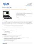
1. Introduction
Tripp Lite’s NetCommander™ IP Console KVM Switch is ideal for controlling multiple servers over inexpensive Cat5e cable from a single console
(keyboard, mouse and display). It includes the following premium features:
• 16-port IP KVM switch with built-in keyboard, monitor and touch pad console
• Access and control multiple computers from a single console (local or remote).
• Achieves BIOS-level control of any server, regardless of server condition and network connectivity. Covers the entire spectrum of crash scenarios.
• Compatible with all major operating systems. Supports many hardware and software configurations for the remote client, target server and KVM switch,
including USB and PS/2 port connections.*
• Secures control of target server from any location via Web browser and standard IP connection.
• Allows multiple simultaneous users to view remote sessions. Remote control is transferable between users with appropriate permissions.
• Supports the highest security standards for encryption (128-bit SSL and HTTPS) and authentication for remote users. Advanced OSD management with
multi-layer security for local users.
• Uses inexpensive and commonly available Cat5 patch cables (maximum distance 100 ft.) to connect to each computer.
* Mac not supported over IP.
2. Important Safety Instructions
SAVE THESE INSTRUCTIONS
This manual contains instructions and warnings that should be followed during the installation and operation of this product. Failure to
comply may invalidate the warranty and cause property damage and/or personal injury.
Installation Warnings
• Install the KVM switch in a controlled indoor environment, away from moisture, temperature extremes, flammable liquids and gasses, conductive
contaminants, dust and direct sunlight.
• Operate the KVM switch at indoor temperatures between 32° F and 104° F (0° C and 40° C).
• When connecting the KVM switch to the facility’s power supply circuit, ensure that the circuit is not overloaded.
Rackmount Warnings
• Ensure there is adequate airflow within the rack.
• Mount the KVM switch evenly within the rack to eliminate potentially hazardous uneven mechanical loading conditions.
• Ensure all rackmount equipment is reliably grounded.
Connection Warnings
• Use of this equipment in life support applications where failure of this equipment can reasonably be expected to cause the failure of the life support
equipment or to significantly affect its safety or effectiveness is not recommended. Do not use this equipment in the presence of a flammable anesthetic
mixture with air, oxygen or nitrous oxide.
• Ensure that the cables used with the KVM switch are not close to any sources of electrical noise interference such as fluorescent lights, HVAC systems
or motors.
• Ensure that the distance between any computer and the KVM switch does not exceed 100 ft.
• Shut down all PS/2 computers before connecting the keyboard, monitor and mouse to ensure they will be recognized by the computer.
Maintenance Warnings
• The KVM switch does not require routine maintenance. There are no user-serviceable parts inside. Only authorized service personnel should open the
case for any reason. Disconnect the unit from AC input power before servicing.
2
3. System Components
The NetCommander IP Console KVM Switch consists of:
• B070-016-19-IP Console KVM Switch
• Rackmount hardware
• 1 serial download cable (DB9 Female to RJ11 Male) for firmware upgrades
Accessories, available separately from Tripp Lite, include:
• Server interface units (SIU)–PS/2 (model # B078-101-PS2) or USB (model # B078-101-USB)
• Cat5 cables (model # series: N001-, N002-, N201- or N105-)
4. Compatibility
The NetCommander IP Console KVM Switch is compatible with:
• PS/2 and USB computers/servers
• VGA, SVGA or XGA monitors
• Windows 2000 or higher, Linux, UNIX and other major operating systems*
• Internet Explorer 6.0 or later versions (128 bit encryption support is required).
* Mac not compatible over IP.
3
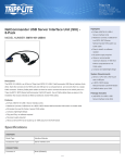
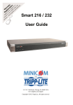
5. Features
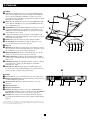
Front View
6
1 Auto: When the LCD Menu is closed, pressing the AUTO button will
1.
2
2.
3
3.
4
4.
5
5.
6
6.
7
7.
8
8.
9
9.
10
10
11
11
12
12
13
13
perform an Auto Adjust on the monitor screen. When the LCD Menu is
open, pressing the AUTO button will bring you back to the previous
screen/selection. If the LCD Menu cannot go back any further, the AUTO
button will close down the menu.
Menu: When the LCD Menu is closed, pressing the MENU button will
open it. When the LCD Menu is open, pressing the MENU button will
select a highlighted option.
On/Off Button: Pressing this button will turn the monitor screen on or off.
< : When the LCD Menu is open, pressing the < button will move the
highlight bar to the left. When modifying a selected option, pressing the
< button will decrease the option.
> : When the LCD Menu is open, pressing the > button will move the
highlight bar to the right. When modifying a selected option, pressing the
> button will increase the option.
Handle: Pull to slide the module out; push to slide the module in.
19” LCD Monitor: After sliding the module out, flip up the cover to
access the LCD monitor, keyboard and touch pad.
Keyboard
Slide Release: Mechanism to lock the drawer closed when the console is
not in use. Prevents it from accidentally sliding open. To slide the console
out, you must first release it by moving the tab sideways.
Rackmounting Brackets: There are rackmount brackets to secure the
chassis to a system rack located at each corner of the unit.
2-Button Touch Pad: Left button is left click, right is right click. Run
your finger up or down the far right side of the touchpad to scroll up and
down a screen.
LCD Display Controls: The LCD OSD controls located here control the
position and picture settings of the LCD display. See LCD OSD
configuration for details.
Railway Release Tabs: When the drawer is completely pulled out to
the end, the railway system will lock. Push the release tabs on both sides
to release the drawer so that it can be pushed back in.
10
7
12
8
13
11
9
1
2
3
4
5
7
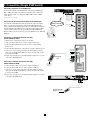
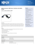
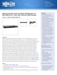
Back View
1 Power Socket: The power cord from the AC power source plugs in here.
1.
2 Firmware Upgrade Port: Plug the included firmware cable into this port
2.
to download firmware upgrade data.
3 CPU Port Section: Plug Cat5e cables from each PC or server into
3.
4
4.
5
5.
6
6.
7
7.
SERIAL
9
10
11
12
13
14
15
16
LAN
1
2
3
4
5
6
7
8
INTEGRATED
CONSOLE PORTS
16-PORT CONSOLE KVM SWITCH
100-240VAC, 50/60 Hz
these ports.
KVM Console Ports*
Integrated Console Ports*
LAN Port: This RJ45 port enables connection to 10/100mb Ethernet.
The LINK LED illuminates to indicate a LAN connection. The REMOTE
LEED illuminates to indicate that a remote session is in progress.
Serial Port: The serial port is not currently functional. It is provided
for possible functionalities that may be made available in future firmware
upgrades.
* The B070-016-19-IP comes with a jumper cable connecting the KVM Console Ports and the Integrated Console
Ports. Do not remove the Jumper Cable unless you are installing a Tripp Lite B050-000 IP Remote Access Unit. For
details, consult the B050-000 installation instructions.
4
KVM CONSOLE PORTS
4
1
UPGRADE
2
6
3
MODEL: B070-016-19-IP
5
6. Rackmount Installation
The B070-016-19-IP is designed for mounting in a 1U rack system. For convenience, a rack mounting kit is included with your B070-016-19-IP for quick
installation. The various mounting options are explained in the sections that follow.
Standard Rackmounting
The standard rackmounting brackets that come attached to the B070-016-19IP allow the unit to be installed in standard 1U racks by a single individual.
1.Slide out the rear mounting brackets from the console and mount both
brackets (separate from the console) to the inside rear of a standard 1U
rack system using user-supplied screws.
2.Take the console and gently slide it into the two rear-mounted brackets in
the rack and secure the console in place by inserting user-supplied screws.
2-Post Rackmounting
The B070-016-19-IP can also be mounted in a 2-post rack installation using
the optional 2-Post Rackmount Kit (model #: B019-000). The mounting
hardware allows for the console to be opened with the drawer in any position.
Heavy-duty 14-gauge steel provides stability and prevents the console frame
from twisting. See the B019-000 instructional manual for detailed mounting
instructions.
1.
5
2.
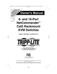
7. Connection (Single KVM Switch)
Connecting Computers to the KVM Switch
Connect each computer to the KVM switch using a Tripp Lite B078-101PS2* or B078-101-USB* Server Interface Unit (SIU), and a Cat5e Patch
Cable. (For best results, use a Tripp Lite N001-, N002-, N201- or N105series cable.*)
SERIAL
9
10
11
12
13
14
15
16
LAN
1
2
3
4
5
6
7
8
INTEGRATED
CONSOLE PORTS
16-PORT CONSOLE KVM SWITCH
100-240VAC, 50/60 Hz
UPGRADE
KVM CONSOLE PORTS
MODEL: B070-016-19-IP
To LAN port
*Available Separately from Tripp Lite.
hp workstation b2600
hp workstation b2600
MIN
ICO
M
To servers
Internet / VPN / LAN
ICO
M
hp workstation b2600
MIN
Connecting Server Interface Units (SIUs) to the KVM Switch
Server Interface Units (SIU) draw their power from the connected computer.
In the case of the PS/2 Server Interface Unit (model # B078-101-PS2), the
power is drawn from the keyboard port. In the case of the USB Server Interface
Unit (model # B078-101-USB), the power is drawn from the USB port. When
connected and receiveing power, the green LED on the SIU will illuminate.
When the SIU is connected to the active port on the KVM, the orange LED will
illuminate.
PS/2 or USB SIU
hp workstation b2600
User over IP
hp workstation b2600
hp workstation b2600
hp workstation b2600
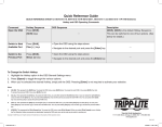
Connecting a PS/2 Server Interface Unit (SIU)
(Model # B078-101-PS/2)
1.Shut down the computer being connected to the SIU.
2.Connect the SIU’s VGA connector to the computer’s VGA port.
3.Connect the SIU’s PS/2 keyboard connector to the computer’s PS/2
keyboard port.
4.Connect the SIU’s PS/2 mouse connector to the computer’s PS/2 mouse port.
5.Connect one end of a Cat5e patch cable to the SIU’s RJ45 port and the
other end to the KVM switch’s RJ45 port. (Note: the Cat5e cable should
be no longer than 100 ft.
6.Repeat steps 1 through 5 for each additional PS/2 computer/server you are
connecting to the KVM switch.
Keybd
100T
To computer’s
mouse port
Mouse
Video
NetCommander
PS/2
Serial B
To computer’s
Video port
SCSI
CAT5 cable to
B072-016-1-IP
Server port
PCI 33Mx32b
PCI 33Mx32b
PCI 33Mx32b
PCI 33Mx32b
To Video port
NetCommander USB
CAT5 cable to B072-016-1-IP
Server port
6
Parallel
Serial A
Connecting a USB Server Interface Unit (SIU)
(Model # B078-101-USB)
1.Connect the SIU’s VGA connector to the computer’s VGA port.
2.Connect the SIU’s USB connector to the computer’s USB port.
3.Connect one end of a Cat5e patch cable to the SIU’s RJ45 port and the
other end to the KVM switch’s RJ45 port. (Note: the Cat5e cable should
be no longer than 100 ft.
4.Repeat steps 1 through 3 for each additional USB computer/server you are
connecting to the KVM switch.
To computer’s
keyboard port
To USB Port
8. Connection (Cascading Multiple KVM Switches)
To cascade two or more NetCommander KVM switches off the
NetCommander IP, follow the instructions below. Connect up to 256
computers* using any combination of B072-008-1 and B072-016-1 KVM
switches. You can only cascade 1 extra level of KVM switches onto the
NetCommander IP KVM.
SERIAL
SERIAL
99
10
11
11
12 12
13 13
14
2
3
4
5
6
14
15
15 16
16
INTEGRATED
CONSOLE PORTS
16-PORT KVM SWITCH WITH IP
MODEL: B072-016-1-IP
100-240V AC 50/60Hz
100-240VAC, 50/60 Hz
KVM CONSOLE PORTS
FLASH
UPGRADE
LAN
LAN
1
1
2
3
4
5
6
7
7
8
16-PORT CONSOLE KVM SWITCH
8
MODEL: B070-016-19-IP
Model: B072-016-1-IP
* When all 16 ports have a B072-016-1 cascaded from them.
Note: Access and Target Settings will be limited when cascading off of
the NetCommander IP KVM Switch.
Security for the computers/servers attached to a cascaded KVM cannot
be set up using the Web Configuration Interface. The only security
available is via the cascaded KVM’s OSD. If a user has access to the
cascaded port, they will have access to all computers/servers attached to
the cascaded KVM switch.
Once the cascaded KVM Switch is accessed from the NetCommander IP
KVM Switch, the only way to access the attached computers/servers is via the Keyboard Hotkeys or the OSD. If OSD security is set to on, the only
way to access the attached computers/servers is by using your password to access the OSD. See changing the lower-level OSD Hotkeys on page 18.
The NetCommander IP will not store the Video and Mouse settings for computers/servers attached to a cascaded KVM Switch. The user will need
to adjust the Video and Mouse settings each time they access a computer/server attached to a cascaded KVM switch.
9. Initial Settings (Default IP Address)
9.1 Networks with a DHCP Server
By default, the NetCommander IP automatically assigns an IP address from a DHCP (Dynamic Host Configuration Protocol) server on the connected
network. The DHCP server provides a valid IP address, gateway address and subnet mask. Have your Network Administrator identify the newly assigned
IP Address from the DHCP server. To help locate the IP Address in the DHCP server, reference the MAC Address located on the underside of the
NetCommander IP. The device number (D.N.) can be found in the same location.
9.2 Networks without a DHCP Server
If no DHCP server is found on the network, the NetCommander IP boots with the static IP address:192.168.0.155.
Note! If a DHCP server later becomes available, the unit picks up the IP settings from DHCP server. To keep the static IP address, disable
DHCP – explained on page 7.
10. Static IP Addresses for Multiple KVM Switches
When you want to connect more than one B070-016-19-IP KVM Switch to the same network, and there is no DHCP server; or, you want to use static IP
addresses, do the following:
Connect the NetCommander IPs, one at a time, and change the static IP address of each unit before connecting the next unit.
7
11. Logging into the Web Configuration Interface
Windows Vista Instructions
In order to operate the NetCommander IP using Windows Vista, you must
run Internet Explorer as an Administrator. To run Internet Explorer as an
Administrator, right click on the Internet Explorer Icon on the Quick Launch
toolbar or in the All Programs start menu and select Run as asministrator.
The UAC (User Account Control) will request confirmation of the action.
If you are an administrator, then you will have to confirm the action and
run Internet Explorer. If you are a regular user, then you will have to
provide an administrator’s password in order to run Internet Explorer as an
administrator.
8
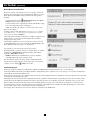
11. Logging into the Web Configuration Interface (Continued)
LOgging In
When first connecting to the NetCommander IP Web Configuration Interface,
a browser security warning appears requesting you to download Tripp Lite’s
SSL Security Certificate. Click Yes to proceed. The warning disappears upon
first NetCommander IP client installation, when the Tripp Lite root certificate
is installed.
1.Open your Web browser (Internet Explorer version 6.0 or higher required).
2.Type the NetCommander IP system IP address, https://192.168.x.xxx/
config, and press Enter. The login page appears, see the figure below.
3.Type the default Administrator user name - admin - and password - access
– (case sensitive).
4.Press Enter. The Web interface opens at the Network Configuration page.
See the figure below.
Note: Bookmark the page for easy reference.
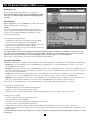
12. Network (Configuration Screen)
Consult your Network Administrator for the network settings.
Device name: Type a name for the NetCommander IP. The default device
name consists of the letter ‘D’ followed by the 6-digit device number (D.N.)
found on the silver label on the underside of the NetCommander IP.
First TCP Port: Choose 3 consecutive ports and type in the first port
number of the series. The default port – 900 – is suitable for the majority of
installations.
Note: Firewall or router security access list must enable inbound
communication through the selected TCP ports for the NetCommander
IPs IP address.
For Client computer access from a secured LAN, the selected ports
should be open for outbound communication.
Enable DHCP – When a DHCP server is active on the same network as the NetCommander IP, the IP Address is automatically assigned.
Note: Where you have access to the server – your configured (or default) NetCommander IP device name will appear on the DHCP server’s
interface, making it easy to locate.
It is recommended that you disable DHCP, and assign a fixed IP address to the NetCommander IP. When DHCP is disabled, enter the IP Address,
Subnet Mask, and Default Gateway as given by your Network Administrator.
When all changes to network settings have been made, click the Save & Restart button.
9
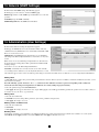
13. Network (SNMP Settings)
From the menu click SNMP settings. The following appears:
From this page you can activate or deactivate SNMP logging.
Enable traps: Check to enable SNMP traps of Smart IP Access events and
operation.
Community: Type the SNMP community
SNMP Manager IP: Enter the SNMP Server IP address
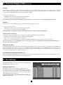
14. Administration (User Settings)
From the menu click User Settings, the figure below appears.
On this page an Administrator can create and edit users. There can be any
combination of users (Administrator, User or View Only), with a limit of 200.
There are 3 levels of user access:
Administrator: An Administrator has unrestricted access to all windows
and settings in the Web Configuration Interface and can take over any active
session.
User: A User can access/control Target Computers/Servers, but cannot use
the advanced mouse settings (Any toolbar options that deal with manually
changing settings.)
A User has no access to the Web Configuration Interface.
View Only: ‘View Only’ Users can only view the screen of the currently
accessed Target Server, without access to the keyboard and mouse. A “view
only” indicator appears on the viewer’s local mouse pointer. Target servers that ‘View Only’ Users are allowed to access are assigned by the Administrator.
Adding a User
1.Click Add and type a name and a password. The password must be at least 6 characters. (Letters or numbers, and must not include the user name, even if
other characters are added.)
Note: The following “special” characters: & < > ” { } cannot be used for either the user name or password. Depending on the security level
chosen, the user name and password parameters are different. (See security settings on page 9 for details.)
2.Select the permission type from the Permission box.
3.Click Apply. The user appears in the list of users. Upon clicking Apply, red text will appear informing you that the operation was successful; or, that you
need to alter one of your choices. (e.g. Password)
Editing a User
1.Select the user from the list.
2.Click Edit. You can now change all the parameters. (User name, permission and password.)
3.Click Apply. The changes are saved.
Deleting a User—To delete a user
1.Select the user from the list.
2.Click Delete.
3.Click Apply. The changes are saved.
Blocking a User
An alternative to deleting a user is blocking a user. This means that the user’s name and password is stored, but the user is unable to access the system.
Check Block and then Apply to block a user. Uncheck Block then click Apply to allow the user access.
10
15. Administration (Switch Configuration)
The Switch Configuration Screen allows the Administrator to give each
computer/server a unique name, making it easier to differentiate between
them. By default, computers/servers are titled Server 1, Server 2, Server 3,
etc. Follow the steps below to update the computer/server name.
1.From the menu click Switch Configuration. The Switch Configuration
window appears, see the figure below.
2.In the Server Name section, change the name of the connected computers/
servers by selecting the desired name and typing a new name. Click Apply
to save changes.
Install Switch Definition File
Also included in the Switch Configuration Screen is a section to install a
new switch definition file. In the event that Tripp Lite updates the Switch
Definition file, the file will be available in the Support section of our website
- www.tripplite.com.
1.Click the Browse button next to the Install Switch Definition File box and
select the new file.
2.A download button will appear next to the selected file. Click on the
button to download the new Switch Definition File.
3. Click the Apply button.
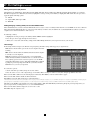
16. Administration (User Targets)
By default, access is denied to all servers for all user types except
Administrators. An Administrator must define the access rights of each
user separately. Follow the instructions below to customize individual user
access.
Note: When cascading a NetCommander KVM Switch off of the
NetCommander IP, any user that has access to the cascaded port will
have access to all computers/servers connected to that port. Any security
restrictions must be done using the cascaded KVMs OSD.
1.From the menu click User Target. The User Targets Configuration
window appears, see the figure below.
2. Select a user from the User drop-down menu.
3.Check the Target servers you want the selected user to have access to. To
select all Target servers, press Select All.
4.Click Apply, saving the selection(s).
5.Repeat the above steps for each user.
11
17. Security (Settings)
The Security Settings Screen allows the Administrator to modify settings
such as Account Blocking, Password Policy and Idle Timeout.
From the Security section click Setting, the Security Settings Screen
appears, see the figure below.
Account Blocking: This allows the administrator to adjust the settings that
cause a user to be blocked from access after entering an incorrect username
and/or password. The administrator can select how many attempts the user
gets to enter the correct information, the time frame within which those
attempts must be made and how long the user is forbidden access after
failing to enter the correct information in the given time period.
Password Policy: You have the option of a standard or high security level
password. The table below shows the parameters of the 2 options.
Standard Security Policy
High Security Policy
8 characters or more must include at least 1 digit
6 characters or more. Cannot and 1 upper case letter and 1 “special” character as
follows ! @ # $ % ^ * ( ) _ - + = [ ] ’ : ; ? / . Cannot
include the user name.
include the username.
Note: The following “special” characters: & < > ” { } cannot be used in either the user name or password. Check the box to enable the high security
password policy. Unchecked, the standard security policy applies.
Idle Timeout: Select the Timeout inactivity period after which the user is disconnected from the system. Choose No Timeout to disable Timeout. During
a Timeout, a user will not be able to make changes in the Web Configuration Interface, nor will they be able to move throughout the Interface’s pages
without re-entering their username and password.
Click Save & Restart to save any configuration changes done to the Security Settings page. The NetCommander IP system restarts with the new changes.
18. Security (SSL Certificate)
This page gives you the option to install your own SSL certificate. Follow
the steps below to install the new certificate.
From the menu, select SSL Certificte, the install SSL Certificate page
appears, see the figure below.
Certificate File: Browse to locate the Certificate file.
Private File: Browse to locate the Private Key file.
Key Password: Type the Key password.
Click Save & Restart.
12
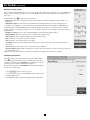
19. Maintenance (Firmware Upgrade)
Upgrade the NetCommander IP firmware to take advantage of new features.
When updated firmware is available, it will be posted in the Support section
of Tripp Lite’s website – www.tripplite.com. If there is no firmware available
on the Tripp Lite website, there is not an updated version available.
From the menu select Firmware Upgrade. The Firmware Upgrade window
appears showing the current firmware version. See the figure below.
1.Verify the current Firmware Version on your NetCommander IP and
match it against the Firmware Upgrade available on Tripp Lite’s website. If
they match, you are running the most current firmware and do not need to
upgrade.
2.If you are not running the most current firmware, locate the Firmware
Upgrade File in the Support section of Tripp Lite’s website and save it to the
currently selected computer.
3.In the Firmware Upgrade screen of the Web Configuration Interface, click
the Browse button and select the Firmware Upgrade File you just saved.
4.Click Start Upgrade. The upgrade starts. On completion, click Reboot.
The unit reboots. After about 30 seconds the Login page appears.
Note: If during a firmware update there is a power failure and you can
no longer access the system, you can restore the device firmware from
the Safe mode. See the Restore Device Firmware section on page 16-17
for instructions on how to do this.
Depending on the type of firmware upgrade, the following settings may
be erased: User settings, server names, mouse and video adjustments. The
network settings remain intact. For more information refer to the firmware
release notes.
20. Restore Factory Settings
You can restore the NetCommander IP unit to the factory settings. This
restores the original NetCommander IP parameters, resetting all the
information added by the administrators, including: Network settings*,
Servers, Switches, Users, Passwords etc.
* You have the option to preserve Network settings – explained below.
Warning: Once reset, the data cannot be retrieved.
To restore factory settings
1.From the menu select Restore Factory Settings. Restore Factory Settings
appears. See the figure below.
2.Check the box if you want to preserve Network settings.
3.Click Restore. Device settings are now restored to their defaults.
21. Saving Changes & Logging Out
Save & Restart: To save any configuration changes and restart the
NetCommander IP click Save & Restart.
Logout: To exit the Configuration menu and close the session, click Logout.
13
22. Starting a Remote Session
Note: Windows Vista users need to log out Internet Explorer as an
administrator. See page 5 for details.
At a Client computer, open Internet Explorer (6.0 and above is required) and
type the Netcommander IP’s IP address, https://192.168.x.xxx. (Only SSL
connections are allowed, therefore type HTTPS, not HTTP before the IP
address). The Login page appears. Type your username and password and
press Enter.
On first connection, install the Tripp Lite Certificate and ActiveX control.
Once connected, the screen of the lowest numbered Target Server that the
user has permission to access appears. The figure below illustrates the
remote session window.
On the remote console you have the following:
Server Confirmation Label: This confirms the identity of the current server
accessed and disappears by default after 30 seconds, (this period can be
adjusted in the OSD – explained in Section II of the guide). It appears again
when switching to a different server. The currently accessed server identity
can be checked any time by looking at the Server Name on the Internet
Explorer title bar.
Toolbar Icon: This is the minimized toolbar from which you switch and
configure the system. Features of the Toolbar are explained in more detail in
the sections below.
Tripp Lite Icon: Hold the mouse over the icon to view information about
current server; connection time and video mode.
23. Taking Over a Busy Remote Session
While only one user can control the KVM and server, multiple remote users
can connect to the KVM at the same time in a “View Only” Mode. All users
will be connected to the same port. When connecting to a busy Target Server
an Administrator has the option to take over the Target Server. A User only
has this option when the current session is run by another User, but not by an
Administrator. The following message appears:
Take Over: Click the Take Over Button to gain full access to the Target
Server. (This function works the same when taking over an attached
computer/server or a cascaded KVM.) The current user will see a prompt
stating they have been taken over, and they will be pushed into View Only
Mode. Once being pushed into View Only Mode, the View Only session will
be disconnected when the other user disconnects.
View Only: Click the View Only Button to allow the current user to remain in
control of the Target Server.
Cancel: Click the Cancel Button to exit the Remote Session.
14
24. Toolbar
Maximize/Minimize the Toolbar
Click the arrow
to maximize or minimize the Toolbar
Dragging the Toolbar to a New Location
When maximized, the Toolbar can be dragged and dropped to anywhere on the screen. Simply drag the Toolbar by the icon
and place it wherever you
like. When minimized, the icon will always remain on the side of the screen, outside the Remote Screen Border. You can drag it to any location you want
on either side of the screen.
Hiding the Toolbar
The Toolbar can be hidden by double-clicking the Netcommander IP System icon
in the lower right corner of the screen. The Toolbar can also be
hidden by pressing the F9 key. To re-display the Toolbar, repeat the above action. You can also set up the Remote Screen to automatically hide the Toolbar
when a user accesses the Target Server via Remote Session.
Switching to a different server
1. From the Toolbar, click
, or right-click
. A list of available servers appears. The currently connected server is highlighted in bold. This area will
allow you access to a cascaded KVM switch; however, once inside you will only be able to access the cascaded KVM’s connected computers/servers by
using the cascaded KVM’s keyboard hotkeys or OSD.
2. Click the desired name to switch to the new computer/server.
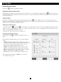
Changing the performance settings
From the Toolbar, click
Right.
. The Performance Settings Box appears, see
The Performance Settings Box allows you to choose from the following
settings:
Adaptive: Automatically adapts to the best compression and colors
according to the network conditions. (Not recommended because network
parameters may change frequently, impacting the user experience).
Low: Select Low for High Compression and 16 colors.
Medium: Select Medium for Medium Compression and 256 colors.
Medium is recommended when using a standard internet connection.
High: For optimal performance when working on a LAN, select High.
This gives a Low compression and High colors (16bit).
Custom: You can choose your own Compression and Color levels.
After choosing the desired settings, click OK. The screen of the last
accessed Target Server appears.
15
24. Toolbar (Continued)
Adjusting the Video settings
Note: The NetCommander IP will not store video settings for all of the computers/servers attached to a cascaded KVM switch.
When accessing a computer/server attached to a cascaded KVM Switch, the user must re-adjust the Video Settings for the
target server.
From the Toolbar, click
. You have the following options:
Refresh: Select Refresh to refresh the Video image. Refresh may be needed when changing the display attributes of a
Target Server.
Manual Video Adjust: Use the manual video adjustment for fine-tuning the Target Server Video Settings after auto
adjustment; or, for adapting to a noisy environment, a non-standard VGA signal or when in full-screen DOS/CLI mode.
To adjust the Video manually click Manual Video Adjust. The manual controls appear, see figure below. Also a red frame
appears around the screen. This represents the screen area according to the Server’s screen resolution. The various settings are
described below.
Brightness / Contrast: Use the scales to adjust the Brightness and Contrast of the displayed image.
Horizontal Offset: Defines the starting position of each line on the displayed image.
Vertical Offset: Defines the Vertical starting position of the displayed image.
Phase: Defines the point at which each pixel is sampled.
Scale: Defines the scale resolution of the session image.
Select Filter: Defines the filter of the input video from the server. A higher filter reduces the noise level but makes the
image heavier.
Noise Level: Represents the Video “Noise” when a static screen is displayed.
Auto Video Adjust: Click Auto Video Adjust. The process takes a few seconds. If the process runs for more than 3 times, there
is an abnormal noise level.
Check the video cable and verify that no dynamic video application is running on the Target Server’s desktop.
Keyboard Key Sequences
Click
to display a list of defined keyboard sequences. When clicked,
these transmit directly to the Target Server, and will not affect the Client
computer. For example, select Ctrl-Alt-Del to send this three key sequence
to the Target Server to initiate its Shutdown/Login process.
To add a keyboard sequence click Add/Remove. The Special Key Manager
box appears. See figure below.
1. Click
. A list of sequences appears.
2. Select the desired sequence and click OK. The sequence appears in the
Special Key Manager box.
3. Click OK. The sequence appears in the Keyboard Key sequence list.
16
24. Toolbar (Continued)
To record a New Key Sequence:
1. From the Special Key Manager Box press Record Now. The Add
Special Key Dialog box appears, see figure below.
2. Give the key sequence a name in the Label field.
3. Click Start Recording.
4. Press the desired keys. The key sequence appears in the area provided.
5. Click Stop Recording.
6. Click OK.
To edit a key sequence:
1. From the Special Key Manager Dialog Box select the desired key.
2. Click Edit.
3. Click Start Recording.
4. Press the desired keys. The keys appear in the area provided.
5. Click Stop Recording.
6. Click OK.
Synchronizing Mouse Pointers
When working at the Client computer, two mouse pointers appear: the
Client computer’s and the Target computer’s. The Client computer’s
mouse runs on top of the Target Server’s. The mouse pointers should be
synchronized so you can only see the one mouse pointer when the mouse is stationary. The following explains what to do if they are not synchronized.
Note: The NetCommander IP will not store Mouse Settings for computers/servers attached to a cascaded KVM Switch. The User will have to
update these settings every time they access a target server connected to a cascaded KVM.
Pre-Mouse Synchronization Tips:
Before accessing a target server remotely, it is recommended that you go into the target servers mouse settings and uncheck the ‘Enhance Pointer Precision’
box. If this box is checked, Mouse Synchronization will not work.
If the Video Noise Level is above zero, calibration may not work. Go to Video Adjustment and try to eliminate the noise by pressing Auto video adjust and/
or adjusting the bars in Manual video adjust.
Calibrating the Mouse Pointers
If the mouse settings on the Target Server were ever changed, or when the Operating System on the Target Server is Windows XP, 2003 Server, Vista,
Linux, Novell, or SCO UNIX, you must synchronize the mouse pointers manually. See the Manual Mouse Synchronization section for details.
Calibrate Button in the toolbar. NetCommander IP saves this alignment so
To calibrate the mouse pointers (For Windows NT4, 98 or 2000) click the
calibration is only needed once per Target Server.*
* NetCommander IP will not save the Mouse Settings of units connected to a cascaded KVM switch. You will need to adjust the settings for these units each time you access them. Also, settings will be saved for the computer/server
currently connected to that port on the NetCommander IP. If computers/servers are ever changed on a port, the Mouse Settings will need to be readjusted.
Calibrating automatically discovers the mouse speed of the Target Server and aligns the two pointers. If the two mouse pointers don’t align after
calibrating, try moving the mouse a little bit on the computer screen. If that does not work, click
/ Align on the toolbar. If the mouse pointers still don’t
align, follow the Manual Mouse Synchronization instructions in the following section. When aligned, it is possible that one mouse pointer will be faster
(or slower) than the other, causing them to break apart when moving. If this occurs, go into the Mouse Settings of both the Client Computer (the computer
you are using to remotely access the NetCommander IP) and the Target Server (the computer/server you are remotely accessing) and set the mouse pointer
speed to the same value. If the mouse pointers are still not moving at the same speed, it may be that the settings on one computer were customized at one
point, changing the values on the mouse pointers speed settings bar. You may need to try increasing/decreasing the mouse pointer speed on one of the
computers to see how it affects the two mouse pointers. This will give you an idea of what adjustments need to be made to get the two pointers moving at
the same speed.
Note: There is normally some lag when moving the pointers . This natural latency comes from the time delay in the internet and can be affected by
the speed of your internet connection as well as other internet related factors.
If the NetCommander IP cannot automatically calibrate the two mouse pointers, it will pull up the Manual Mouse Synchronization box.
17
24. Toolbar (Continued)
Manual Mouse Synchronization
If the mouse settings on the Target Server were ever changed, or when the
Operating system on the Target Server is Windows XP / 2003 Server / Vista,
Linux, Novell or SCO UNIX you must synchronize the mouse pointers
manually.
1. From the Toolbar click the
Manual Settings Button. The Mouse
Settings Dialog box appears. See figure below.
2. Select the Target Server’s Operating System and click OK. The settings
for the selected Operating System are displayed.
3. Make sure that all of the settings are set to the same as those on the
Target Server/Computer.
For Windows NT4, 98, ME, 2000 (If Mouse Properties were ever changed
for the Target Server – even if they have been returned to their original
state) uncheck the default - Default box.
4. The USB option in the Mouse Settings box is available for Target Servers/
Computers that are connected to the NetCommander IP via USB and
unsupported operating systems.
5. In the Mouse Settings box, you can select the type of mouse connected
to NetCommander IP’s local console by clicking the Advanced button. The
Mouse Emulation Dialog box appears. See figure below.
Select the mouse connected to the Local Console port on the
NetCommander IP. (e.g. if the local mouse is a 2-button mouse or a 2-button
touchpad, select Standard Mouse. Anything with more than 3 buttons
should have Wheel Mouse checked)
Max Rate: This defines the maximum mouse report rate. Default is
compatible with the majority of operating systems.
Once all settings are checked, the mouse pointers should automatically
align. If they do not align right away, try moving the mouse around on the
computer screen or clicking
/ Align on the toolbar.
Troubleshooting Tips
If the mouse pointers do not align after following the Calibration and Manual Mouse Settings instructions above, try the following:
Verify that the Enhanced Pointer Precision Box in the Mouse Settings Window of the computer/server you are trying to access is unselected. If this box is
checked, Mouse Synchronization will not work.
If the Video Noise Level is above zero, calibration may not work. Go to Video Adjustment and try to eliminate the noise by pressing Auto video adjust and/
or adjusting the bars in Manual video adjust.
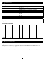
Although the chart at the back of this owner’s manual shows all of the compatible resolutions and their corresponding refresh rates, there are instances when
lowering the refresh rate will help synchronize mouse pointers. If your mouse pointers are not aligning, and you notice a black bar on the top or side of the
Remote Computer Screen Border, the Video may need to be manually adjusted or you may need to set the Target Server/Computer at a lower refresh rate.
Try changing out the Cat5 cable connecting the Target Server/Computer to the KVM switch or use N105 series STP cable by Tripp Lite. Any noise that
exists in a faulty cable can have a negative impact on mouse synchronization.
Try changing out the SIU being used to connect the Target Server/Computer to the KVM switch.
18
24. Toolbar (Continued)
Disconnecting the Remote Session
To disconnect the session, on the Toolbar, click the
Tripp Lite Icon Menu Features
button. The Login page appears, allowing you to re-login or close the browser window.
Right-clicking the Tripp Lite Icon
will pull up a menu. From this menu you can access the connected devices using the following features.
Disconnect: Disconnect the remote session by clicking Disconnect. You can also Disconnect by using the Disconnect button on the Toolbar.
About: This verifies the Client, Firmware, Keyboard/Mouse Emulation (KME) Firmware and Switch File Versions installed on your Netcommander IP.
Local Settings: Click Local Settings to pull up the Client Configuration Dialog Box. See figure below.
Pointer type: From the Drop-down menu you can change the appearance of the Client Computer Mouse Pointer. It can be set to appear as the Client
Mouse Pointer directly on top of the Target Server Mouse Pointer (Default), as a dot or to not appear at all.
Hide Toolbar: Check this option to hide the Toolbar from the next reconnection onwards. To toggle the Toolbar on and off, press F9 or double-click the
System tray icon
.
Full Screen Mode: Check this option to make the remote session screen appear in full screen mode from the next reconnection onwards.
To work in full screen mode:
1. Ensure that the Client computer has the same screen resolution as the Target Server.
2. Select the Full Screen option from the Icon Menu or press F11. The Internet Explorer window disappears, leaving the Internet Explorer menu bar at the top.
3. Right click the Internet Explorer menu bar and check Auto-Hide. The Internet Explorer menu bar disappears. You are in full screen mode.
To exit full screen mode:
Press F11. Or place the mouse at the top of the window to display the Internet Explorer toolbar and click Restore button.
Configuration: This only appears in the menu when an Administrator is logged in. Click Configuration to access the Web configuration interface.
25. Safe Mode
If you are in a situation where you can’t access the Web Configuration Interface using the usual method, you can do the following while in Safe Mode:
Restore Factory Defaults: When you cannot access the system (e.g. you have forgotten the Username or Password) you can restore the NetCommander
IP’s factory defaults from the Safe Mode.
Restore the Device Firmware: If during a firmware update there is a power failure and you can no longer access the system, you can restore the device
firmware from the Safe Mode.
Entering Safe Mode
1. Turn the NetCommander IP KVM Switch Off .
2. Press and hold down the Local button for 3-4 seconds, while at the same
time powering up the Netcommander IP. The NetCommander IP boots up in
Safe Mode.
3. When the NetCommander IP has booted up in Safe Mode, and you
are connected to a network with a DHCP server, a new IP Address will
be pulled. Have your Network Administrator identify the newly assigned
IP Address from the DHCP server. To help locate the IP Address in the
DHCP server, reference the MAC Address located on the underside of the
NetCommander IP. The device number (D.N.) can be found in the same
location. If there is no DHCP server, the unit boots with the static IP address
192.168.2.155.
4. Open Internet Explorer and type the following into the Address box:
http://192.168.x.xxx/config. (Do not start the address with HTTPS) Vista
users need to log onto Internet Explorer in administrator mode. The Login
Page appears. See figure below.
5. Type Username: admin and Password: SAFEmode. (Case sensitive).
This username and password works only in Safe mode. A menu appears, see
figure below.
19
25. Safe Mode (Continued)
Restoring Factory Defaults
1. From the Safe Mode Menu choose Restore Factory Settings. A warning
appears, see figure below.
2. Click Restore. A further warning appears, see figure below.
3. Click OK, the factory defaults are restored. When the process finishes
the figure below appears.
4. Click Reboot to restart the unit.
Restoring the Device Firmware
Contact Tripp Lite Technical Support at 773-869-1234 to receive the Upgrade firmware required to restore the device firmware. Save the Upgrade firmware
on the hard disk of a computer connected to the network.
To restore the device firmware:
1. From the Safe Mode Menu choose Firmware Upgrade.
2. Locate the Upgrade firmware and click Install, then click Start Upgrade. When the process finishes the figure below appears.
3. Click Reboot to restart the unit.
26. On Screen Display (OSD)
Switching Between Computers
When at the local console you can switch between connected computers using Keyboard Hotkeys and the OSD.
Keyboard Hotkeys: To switch to the next computer, press and release the [Shift] key, then press the [+] key. To switch to the previous computer, press
and release the [Shift] key, then press the [-] key.
Note: You can use the [+] key of the alphanumeric section or of the numeric keypad on a US English keyboard. With a Non-US English keyboard, use
the [+] key of the numeric keypad only.
The On Screen Display (OSD)
Before accessing the OSD, make sure that the NetCommander IP is not
being accessed remotely. (The Remote LED on the front of the unit will be
lit if a remote session is in progress.) To gain access to the NetCommander
IP, press the Local button on the front of the unit.
Press and release the Shift key twice to open the OSD Main Menu. Lines
with Blue text represent ports that have a computer/server connected to
them, which is currently turned on. Lines with Gray text represent ports that
either have a computer/server connected to them, which is turned off; or
they have no computer/server connected at all. The Type column indicates
whether a computer/server (C) is connected to the port or a KVM Switch
(S) is connected to the port. For the Type column to display S, the user must
change the Hotkey setting for the cascaded KVM.
Navigating the OSD: To move up and down, use the and arrow keys.
To jump from one column to the next (when relevant), use the [Tab] key. To
exit the OSD or to return to the previous OSD window, press [Esc].
Port Number Appears here
Selecting a computer: To select a computer:
1. Move to the desired computer line.
2. Press the Enter key. The selected computer will be accessed and the OSD screen will close.
Note: While the OSD Screen is active the Keyboard Hotkey Commands and Mouse will be deactivated.
20
C=computer
Instruction Keys
26. On Screen Display (OSD) (Continued)
OSD Settings – F2
Press F2 to open the OSD Settings Window. See the figure below.
Note: If the OSD is password protected, only the Administrator will be
able to get access to the F2 settings window by using the appropriate
password.
General Settings
With the highlight line on the word GENERAL, press [Enter]. The General
Settings window appears (see figure below).
Security
The Security option in the OSD General Settings Menu allows you to
activate or deactivate the OSDs Password Security. By default, Password
Security is set to Off. Only the Administrator will be able to activate/
deactivate Password Security.
To activate/deactivate Password Security:
1. Highlight the Security option in the OSD General Settings Menu.
2. Press the space bar to change Password Security On/Off.
3. Pressing the space bar will display a prompt requiring you to enter the
Security Password. (Security Password defaults as ‘Admin’)
4. Once you’ve typed in the correct password and hit enter, the Password
Security status will be changed.
Note: Once Password Security is activated, Hotkey Commands will be deactivated, leaving you limited to the OSD Menu as your only way to select
a port. Once you leave the OSD Menu, you will need to hit the ‘Shift, Shift’ command to access the OSD Menu and select another port. You will be
required to enter your password each time you enter the OSD Menu. This does not affect Remote Access to the KVM Switch.
OSD Security is separate from the security features set up in the Web Configuration Interface.
Changing the OSD Hotkey
By default the primary Hotkey is the Shift key. You have the ability to replace the Shift key with one of four different choices in the OSD General Settings Menu.
(SH-SH): This represents the Shift key. To access the OSD Menu press ‘Shift, Shift.’ To access the next KVM in line press ‘Shift, +.’ To access the
previous KVM in line press ‘Shift, -.’
(CL-CL): This represents the Ctrl key. To access the OSD Menu you can either press the Left Ctrl key 2 times or you can press the Right Ctrl key once
and then the Left Ctrl key. You can press either Ctrl key once and the + key to access the next KVM in line. You can press either Ctrl key once and the key to access the previous KVM in line.
(CLF11): This represents the Ctrl key and the F11 key. To access the OSD Menu you press either Ctrl key and then F11. You can press either Ctrl key
once and the + key to access the next KVM in line. You can press either Ctrl key once and the - key to access the previous KVM in line.
(PRSCR): This represents the Print Screen key. To access the OSD Menu you press the Print Screen key once. When you select Print Screen as your
hotkey, the port selection hotkey commands are deactivated, leaving the OSD Main Menu as the only way to switch to another port.
When you have cascaded KVM switches, a lower level Switch must have a different OSD display hotkey than a higher-level switch.
To change the top-level switch hotkey:
1. Highlight the Hotkey option in the OSD General Settings Menu.
2. Press the space bar to toggle through the various options.
3. When you’ve selected the desired hotkey, simply exit the OSD. Pressing the Enter key is not required to activate your selection.
To change a lower level hotkey:
1. Connect a keyboard and monitor to the lower level switch.
2. Press Shift, Shift to open the OSD Menu.
3. Press F2 to get to the General Settings Menu, and highlight the Hotkey option.
4. Press the Space Bar to toggle through the various hotkeys
5. When you’ve selected the desired hotkey, simply exit the OSD Menu. Pressing the Enter key is not required to activate your selection
6. Follow the instructions in the Port Settings section on page 19 to update the Port Settings menu in the top-level KVMs OSD to reflect the lower-level
KVMs new hotkey
Note: When Password Security is activated, all port selection hotkey commands are deactivated, leaving the OSD Main Menu as the only way to switch
to another port.
21
26. On Screen Display (OSD) (Continued)
Auto Skip
The Auto Skip option allows you to choose whether you want Inactive ports to be selectable or not. If the Auto Skip option is turned on, Inactive ports will
not be accessible via the OSD Main Menu or the Port Selection Hotkey Commands. If the Auto Skip option is turned on, you will be able to access Inactive
ports using either the OSD Main Menu or the Port Selection Hotkey Commands.
To change the Auto Skip setting:
1. Highlight the Auto Skip option in the OSD General Settings Menu
2. Press the space bar to turn the Auto Skip option On/Off
Note: Changing the Auto Skip setting in the OSD does not affect what ports you can select when accessing the NetCommander IP remotely.
Serial Port
The Serial port is used for the Firmware upgrade. Serial port On means the program can be used.
To change the Serial port setting:
1. Highlight the Serial Port option in the OSD General Settings Menu.
2. Press the space bar to turn the Serial Port option On/Off.
Note: This reference to serial port has nothing to do with the port labeled “serial” port on the back of the KVM.
Changing the Keyboard Language
The keyboard is preset to US English. It can be changed to French (FR) or German (DE) by doing the following:
1. Highlight the Keyboard language option in the OSD General Settings Menu
2. Press the space bar to toggle through the various options.
3. When you’ve selected the desired language, simply exit the OSD. Pressing the Enter key is not required to activate your selection
Note! You can use the [+] key of the alphanumeric section or of the numeric keypad on a US English keyboard. With a Non-US English keyboard, use
the [+] key of the numeric keypad only.
Editing the Switch Name
The KVM Switch Name appears at the bottom of the OSD General Settings Menu, and can be changed to whatever you want. When cascading KVMs onto
the NetCommander IP, it is necessary to access the cascaded KVMs OSD using its own hotkey. Giving cascaded KVM OSDs unique names makes it easier
when accessing them to verify which switches OSD you are accessing. To change this name simply type over the existing letters. You can create a name up
to 18 characters in length, with spaces counting as characters.
Reset OSD General Settings Menu to Defaults (F7)
When in the OSD General Settings Menu, you can reset all of the options to the original default settings, erasing any changes you have made. If you have
changed the Security Passwords, they will be reset to their defaults as well.
27. Port Settings
In the OSD Settings Menu (Access by pressing F2 in the OSD Main Menu),
highlight the Ports option and press enter.
Editing the computer name
By default each port is named ‘Computer 01, Computer 02, etc.’ To
personalize these names for each computer, highlight the desired port and
type directly over the text that’s already there. Each name has a maximum
of 15 characters, each space counting as one character. To delete a character,
simply highlight it and press the space bar.
Note: The computer name can also be edited in the web configuration
interface. (See section 14.)
22
27. Port Settings (Continued)
Editing the Keyboard (KB) Column
The KVM operates with Windows, Linux, HP UX, Alpha UNIX, SGI, DOS, Novell, USB or Open VMS. By default the Keyboard Mode is set to PS for
Intel Based computers. For a different keyboard mode, highlight the desired port and press the Tab key to highlight the KB column. Press the space bar to
toggle through the following options:
U1 - HP UX
U2 - Alpha UNIX, SGI or Open VMS
U3 - IBM AIX
Adding/Changing a Hotkey (HKEY) for Cascaded KVM Switches
When a KVM Switch is cascaded to the NetCommander IP, it is necessary to select a new hotkey in this field. The cascaded KVMs need to have a different
hotkey than the NetCommander IP they are connected to. If the hotkeys are left the same, the OSD for the cascaded KVM will not work. For connected
computers/servers this field should have “NO” selected.
To add/change a hotkey:
1. Highlight the desired port and press the Tab key until the HKEY column is highlighted
2. Press the space bar to toggle through the various choices
3. When you’ve selected the desired hotkey, simply exit the OSD. Hitting the Enter key is not required to activate your selection
Time Settings
In the Settings window navigate to the Time line and press [Enter]. The Time settings window appears (see figure below).
SCN: Sets the amount of time spent on the selected computer when Auto
Scanning.
LBL: Sets the amount of time the OSD label that shows which computer
is currently accessed is displayed.
T/O: When password protection is activated, you can automatically
disable the Keyboard, Mouse and Monitor after a set amount of inactive
time, requiring a password to be entered to regain access to the KVM
switch. When Timed Out, press the ‘Shift, Shift’ OSD Hotkey Command
to pull up the password prompt, which will take you back to the OSD
Main Menu once you enter your password.
To set the above periods:
1. On the desired line press Tab to jump to the desired column.
2. Place the cursor over one of the 3 digits and type a new number. Enter a leading zero where necessary. For example, type 030 for 30 seconds.
Enter 999 in the LBL column to have the label displayed continuously. Enter 000 if you do not want the label to appear.
Enter 999 in the T/O column to disable the Timeout function.
Enter 000 if you want the Timeout function to work immediately.*
* This will literally cause the Timeout function to begin immediately when the computer port is selected. This will essentially freeze access to the KVM, not allowing the user enough time to hit the OSD Hotkey Command to pull up the
password prompt. It is recommended that you always keep the T/O set to 5 seconds or higher. If you set the T/O at 000 and get locked out of the KVM, turn the B070-016-19 Console KVM Off and then back On.
This will reset the KVM, leaving a blank screen on the monitor. Hit the ‘Shift, Shift’ OSD Hotkey Command to pull up the password prompt. Once you
type in your password, you will again have access to the OSD Main Menu.
Enter 999 in the SCN column to display the screen for 999 seconds.
Enter 000 to skip the computer screen.
23
28. Security
The OSD offers an advanced password security system made up of three
different security levels, each having its own access rights.
Administrator (Status A): The Administrator has access to all features of
the KVM, allowing them to Set/Modify all Passwords and Security Profiles
and gain full access to any computer connected to the KVM and usage of all
OSD features.
Supervisor (Status S): The supervisor has full access to all computers
connected to the KVM and can use the Auto Scan (F4), Tuning (F5) and
Confirmation Label Moving (F6) functions in the OSD. The Supervisor
can’t change any of the OSD Settings or Security Settings.
User (Status U): There can be up to 6 Users set up by the Administrator
for access to the KVM. Users are able to use the OSD Main Menu to access
a connected computer and can use the Auto Scan (F4), Tuning (F5) and
Confirmation Label Moving (F6) functions in the OSD. Users do not have the ability to use any other OSD features. The Administrator will choose which
computers they have access to and which they do not. There are 3 types of access the Administrator can give a User:
Y - This gives the user full access to a connected computer.
V - This gives the user view only access to a computer. Keyboard and mouse functionality are not available.
N - This means a user is not allowed to access a connected computer. If the User attempts to access a computer they are not allowed to, a blank screen
will appear.
Security Settings
When Password Security is set to on, only the administrator can change the Security Settings of the KVM switch.
Changing Security Settings:
1. Highlight the Security option in the OSD Settings Menu and press the Enter key.
2. To change the name of the Administrator, Supervisor or User, highlight the desired name and simply type over what’s already there. Any letters left
over can be deleted by pressing the space bar.
3. To change the password, hit the Tab key to highlight the Password column of the desired person and type in the new password.
4. The last column (T) refers to the level of access; Administrator (A), Supervisor (S) or User (U). You can change these if you want, but there can only
be 1 Administrator, 1 Supervisor and 6 Users.
29. User Settings
1. Highlight the Users option in the OSD Settings Menu and hit the Enter
key.
2. The Users will be represented in the 6 columns on the right side of the
screen. To change the access for a given computer, highlight the desired
computer and hit the Tab key until the desired user is highlighted.
3. Press the space bar to toggle between the 3 access options (Y, V or N).
See “User Status (U)” section for details on these 3 options.
OSD HELP Window (F1)
To access the HELP window press F1. The HELP window is displayed. See
figure below.
Note: All the functions in the Help window are performed from the OSD
Main Menu. The Help window only serves as a reminder of the OSD
function keys.
24
30. Scanning Computers (F4)
The amount of time spent on a computer when Auto Scanning is adjustable.
To activate scanning:
1. Press the [Shift] key twice to activate the OSD.
2. Press the [F4] key.
Each active computer will be displayed in sequence. A Scan label appears in the top left corner.
To deactivate scanning:
Press [F4].
31. Tuning (F5)
You can tune the image of any remote computer screen. To adjust the screen image:
1. In the OSD Main Menu highlight the computer you want to adjust.
2. Press the [F5] key. The screen image of the selected computer is displayed, along with the Image Tuning label.
3. Adjust the image by using the Right and Left Arrow keys.
4. When the image is satisfactory, press [Esc].
Note! Distance affects picture quality. The further away a remote computer is from the KVM, the lower the image quality and the more tuning needed.
Therefore put any higher resolution computers closer to the KVM.
32. Moving the Label (F6)
You can position the OSD label anywhere on the screen. To position the label from the Main window:
1. Move to the desired computer using the Up and Down Arrow keys.
2. Press the [F6] key. The selected screen image and Identification label are displayed.
3. Use the arrow keys to move the label to the desired position.
4. Press [Esc] to save and exit.
33. Upgrading the NetCommander IP Firmware
System Requirements for Firmware Upgrade
• Pentium 166 or higher with 16MB RAM and 10MB free Hard Drive space
• Free Serial port
• Windows 2000 and later
• To update the firmware the KVM system must be connected and switched on.
Software
With the NetCommander KVM Update software program you can upgrade the firmware for the:
• OSD
• B070-016-19-IP KVM
• Server Interface Units
KVM Update enables you to add new features and take advantage of product improvements in a quick and efficient manner.
25
33. Upgrading the NetCommander IP Firmware (Continued)
SERIAL
9
10
11
12
13
14
15
16
INTEGRATED
CONSOLE PORTS
16-PORT CONSOLE KVM SWITCH
100-240VAC, 50/60 Hz
UPGRADE
KVM CONSOLE PORTS
LAN
1
2
3
4
5
6
7
MODEL: B070-016-19-IP
8
To Flash
connector
RS232 Download
cable
MIN
ICO
M
Update software
installed here
SIUs to servers
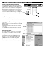
Starting and Configuring the KVM Update
1. Start the KVM Update software. The KVM Update window appears
(see figure below).
The table below explains the functions of the buttons and boxes in the KVM
Switch Update window.
2. From the Options menu choose Com Port. The Com Port box appears
(see figure below).
3. Select the COM Port of the Upgrade Computer that you connected the
RS232 Serial Firmware Upgrade Cable to. If it is not connected to the COM
Port you’ve chosen, the Firmware Upgrade will fail.
Verifying the Version Numbers
Before upgrading your firmware, verify that you are not already using the
most current firmware. To do this, obtain the firmware version number
using the steps below, and compare it with the firmware version number on
www.tripplite.com. You’ll also need to verify the hardware version number
of your KVM Switch and SIU(s), in the case that the firmware upgrade is
not compatible with your current unit. Compatible hardware version
numbers will also be posted on www.tripplite.com. In the event that
your KVM Switch or SIU(s) are not compatible with the firmware
upgrade, you will not be able to install the firmware upgrade unless you
buy a new unit that is compatible with the upgrade.
* If there is no firmware upgrade currently available, there will be nothing posted on www.tripplite.com
26
MIN
Installing the Software
To install the KVM Switch Update software:
1. Download KVM update software from www.tripplite.com
2. Run the software. If there is no firmware upgrade currently available, there will be nothing posted on www.tripplite.com
ICO
M
Connecting the RS-232 Serial Firmware Upgrade Cable
To run the firmware upgrade software, you must first connect the RS-232
Serial Firmware Upgrade cable between the B070-016-19-IP and a separate
computer (One not connected to the KVM switch) containing the firmware
upgrade software. Note: Each cascaded KVM Switch must be updated
separately. When you’re done updating the first KVM Switch, attach the
RS-232 Serial Firmware Upgrade cable between each cascaded KVM and
the Update Computer. For the firmware upgrade to take place, the Serial
Port option in the OSD General Settings Menu must be set to On. If it is set
to Off, you will not be able to perform a firmware upgrade. When password
security is turned on, the only person who can turn the Serial Port option On
and Off is the administrator.
33. Upgrading the NetCommander IP Firmware (Continued)
The OSD version number
To verify the OSD Version Number
1. Open the KVM Switch Update program.
2. In the Switch Unit box, check the NetCommander Cat5 KVM Switch OSD option.
3. Click F/W Version. The version number appears in the Switch box.
The H/W Version button is grayed out, as there is no hardware relevant to the OSD.
The KVM Manager Version Number
To verify the KVM version number:
1. Open the KVM Switch Update program.
2. In the Switch Unit box, check the NetCommander Cat5 KVM Switch Manager option.
3. Click F/W Version. The firmware version number appears in the Switch Unit box.
4. Click H/W Version. The hardware version number appears in the Switch Unit box.
Verifying the Server Interface Unit’s Version Number
Before you can check a Server Interface Unit, you must uncheck the Switch Unit box options.
To verify the Server Interface Unit version number:
1. Open the KVM Switch Update program.
2. Check one or more or all of the Server Interface Units.
3. Click F/W Version. The firmware version number appears after the Server Interface Unit number.
4. Click H/W Version. The hardware version number appears after the Server Interface Unit number.
When “Not responding” appears, no computer is connected, or it is switched off.
Obtaining New Firmware
Download the latest firmware for your system from www.tripplite.com
Updating the Firmware
Warning: Never switch off any computer connected to the KVM system during the Firmware Upgrade process.
1. Download the latest firmware for your NetCommander IP KVM
Switch from www.tripplite.com
2. Using the Update Computer, open up the Firmware Upgrade Software
3. In the KVM Switch Update Window, select the KVM Switch, KVM
Switch OSD or SIU(s) you would like to upgrade
4. From the File Menu, choose Open to open up the firmware upgrade file
you downloaded from www.tripplite.com and open the file
5. Click the Start button to begin the update. When finished, the firmware
version number will appear next to the unit you just updated
6. Check to make sure the Firmware Version Number is correct by
following the steps in the “Verifying the Version Numbers” section on
page 24. If it does not show up as the most current Firmware Version
Number, start the upgrade over again.
Firmware Update generates one log file per session that displays a
chronological list of actions. You can read the log file in any ASCII text
editor. The log file is located in the Windows directory.
27
33. Upgrading the NetCommander IP Firmware (Continued)
Resetting the KVM Switch or SIU(s)
In the event the KVM Switch or SIU(s) freezes during firmware upgrade or the KVM Console Mouse/Keyboard are not working properly, you can reset
the unit using the Upgrade computer. This will not affect any of the settings on the KVM Switch or SIU. Follow the instructions below to reset your KVM
Switch or SIU.
1. Using the Upgrade Computer, select the KVM Switch or SIU(s) you wish to reset in the firmware upgrade software window.
2. In the Options menu, select the Advanced/Reset option. This will reset the selected KVM Switch or SIU(s). You should now be able to use your KVM
Switch or SIU(s).
Setting Default Values for the OSD
To return the OSD to the factory default settings:
1. Using the Upgrade Computer, select the KVM Switch that you want to reset the OSD for in the firmware upgrade software window.
2. In the Options Menu select the Advanced/Set Default option. A warning appears, click OK. The OSD returns to the factory default settings.
Get Status
If there is a break in communication between the Update software and the system, select Options/Get Status to get the current status of the computers in system.
34. Troubleshooting
Note: Disconnect device from AC mains before service operation!
When using Firmware Update software you may at times get a Communication Error message.
If a Communication Error message does appear during the update procedure, do the following:
1. Ensure that the RS232 Serial cable’s RS232 connector is connected to the Switch’s Communication port.
2. Ensure that the RS232 Serial cable’s DB9F connector is connected to the DB9M Serial port on the CPU’s rear panel.
3. Verify there is no Remote session in progress by pressing the Local button.
4. Restart the download process.
Electricity Failure
If the electricity fails during an update to the KVM firmware, do the following:
1. If the electricity fails while the switch firmware is updating, a Communication Error message will appear. Simply resume the firmware update by opening the
folder that contains the firmware update file and continue from there.
2. If the electricity fails while the Server Interface Unit firmware is updating, a Not Responding or Upgrade Error message will appear. Restart the upgrade from
the beginning.
Monitor Screen Failure
In the event that one of the connected computers does not display an image on the console monitor (your monitor may display an error message saying ‘Unable to
Display Video Mode’), you may need to update the DDC Information from the console monitor. To do this, follow these steps:
1. Remove the SIU VGA Connectors from all connected computers. Leave the USB or PS/2 connectors attached
2. Open the OSD Main Menu and press the F10 key. The OSD will flash the message ‘Please Wait.’ When that message stops, the update has taken place
3. Reconnect the SIU VGA Connectors of all the attached computers. You should now be able to display video from all computers
28
35. Specifications
Technical Specifications
Target Server – Windows, Linux, UNIX and other major operating systems*
Client Computer – Windows 2000 or higher with IE 6.0 or higher and ActiveX
Operating systems
* Mac not compatible over IP.
Resolution
Target Server – Up to 1600 x 1200 @ 85Hz
Client Computer – Recommended - resolution should be higher than on Target Server
Video and mouse synchronization
Both auto and manual modes
Security
128-bit SSL encryption
Connections
Ethernet – RJ45 – 10/100 Mbit/sec autosensing
Serial – RJ45
Local KVM connection – Screen HDD15, Keyboard./Mouse – MiniDIN6
Flash – RJ11
Server – RJ45
Weight (with unit packaging)
1.7kg / 3.75 lbs.
Dimensions (H x D x W)
43mm x 762mm x 483mm / 1.7 in. x 30 in. x 19 in.
Power input
100 – 240 VAC 50 / 60 Hz
Operating temperature
0°C to 40°C / 32° to 104°F
Storage temperature
-25°C to 60°C / -13°F to 140°F
Humidity
80% non condensing relative humidity
Video Resolution and Refresh Rates
Hz
56
640x480
60
65
x
66
70
72
x
x
x
x
x
x
720x400
800x600
1024x768
73
75
76
x
x
x
x
x
1152x864
x
x
x
x
x
x
1152x900
x
1280x720
x
1280x768
x
1280x960
x
1280x1024
x
1600x1200
x
x
x
x
x
x
86
x
x
x
85
x
x
x
x
x
x
36. Storage and Service
Storage
The KVM switch must be stored in a clean, secure environment with a temperature less than 40° C (104° F) and a relative humidity less than 90% (noncondensing). Store the KVM switch in its original shipping container if possible.
Service
The KVM switch is covered by the limited warranty described in this manual. For more information, call Tripp Lite Customer Service at (773) 869-1234.
29
x
37. Warranty & Warranty Registration
Limited Warranty
Seller warrants this product, if used in accordance with all applicable instructions, to be free from original defects in material and workmanship for a period of
2 years (except U.S., Canada and Mexico: 1 year) from the date of initial purchase. If the product should prove defective in material or workmanship within
that period, Seller will repair or replace the product, in its sole discretion. Service under this Warranty includes parts and Tripp Lite service center labor. On-site
service plans are available from Tripp Lite through authorized service partners (in most areas). Contact Tripp Lite Customer Service at (773) 869-1234 for details.
International customers should contact Tripp Lite support at [email protected].
THIS WARRANTY DOES NOT APPLY TO NORMAL WEAR OR TO DAMAGE RESULTING FROM ACCIDENT, MISUSE, ABUSE OR NEGLECT.
SELLER MAKES NO EXPRESS WARRANTIES OTHER THAN THE WARRANTY EXPRESSLY SET FORTH HEREIN. EXCEPT TO THE EXTENT
PROHIBITED BY APPLICABLE LAW, ALL IMPLIED WARRANTIES, INCLUDING ALL WARRANTIES OF MERCHANTABILITY OR FITNESS, ARE
LIMITED IN DURATION TO THE WARRANTY PERIOD SET FORTH ABOVE; AND THIS WARRANTY EXPRESSLY EXCLUDES ALL INCIDENTAL
AND CONSEQUENTIAL DAMAGES. (Some states do not allow limitations on how long an implied warranty lasts, and some states do not allow the exclusion
or limitation of incidental or consequential damages, so the above limitations or exclusions may not apply to you. This Warranty gives you specific legal rights, and
you may have other rights which vary from jurisdiction to jurisdiction).
Tripp Lite; 1111 W. 35th Street; Chicago IL 60609; USA
WARNING: The individual user should take care to determine prior to use whether this device is suitable, adequate or safe for the use intended. Since
individual applications are subject to great variation, the manufacturer makes no representation or warranty as to the suitability or fitness of these
devices for any specific application.
Warranty Registration
Visit www.tripplite.com/warranty today to register the warranty for your new Tripp Lite product. You’ll be automatically entered into a drawing for a chance to win
a FREE Tripp Lite product!*
* No purchase necessary. Void where prohibited. Some restrictions apply. See website for details.
WEEE Compliance Information for Tripp Lite Customers and Recyclers
Under the Waste Electrical and Electronic Equipment (WEEE) Directive and implementing regulations, when customers buy new electrical and electronic
equipment from Tripp Lite they are entitled to:
• Send old equipment for recycling on a one-for-one, like-for-like basis (this varies depending on the country)
• Send the new equipment back for recycling when this ultimately becomes waste
Tripp Lite has a policy of continuous improvement. Specifications are subject to change without notice.
Made in China
30