1
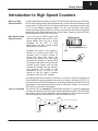
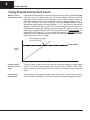
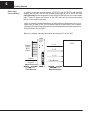
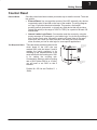
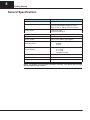
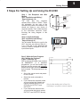
D3–HSC
High-Speed Counter
In This Manual. . . .
— Getting Started
— Installation and Wiring
— Writing the Program
— Putting It All Together – Examples
2
Getting Started
Overview
The Purpose of
this Manual
This manual is designed to allow you to setup
and install your D3–HSC High-Speed Counter
(HSC).
Supplemental
Manuals
Here are two additional manuals that you may find necessary or helpful:
User Manuals
D
DL305 User Manual
part number
D3–USER–M
D
DirectSoft Programming Software
part number
DA–DSOFT–M
Who Should Read
this Manual
If you need a High-Speed Counter for your DL305 PLC and you understand the
basics of installing and programming PLCs, this is the right manual for you.
Quality Technical
Manuals and
Technical Support
We strive to make our manuals the best in the industry, and we rely on your feedback
to let us know if we are reaching our goal. If you cannot find the solution to your
particular application, or, if for any reason you need additional assistance, please
call us at 800–633–0405. Our technical support group is glad to work with you in
answering your questions. They are available weekdays from 9:00 a.m. to 6:00
p.m. Eastern Time. You can also contact us on the worldwide web at:
http://www.plcdirect.com
(PLCDirect Web site for general info/file transfers)
You can also find a variety of support solutions at our 24–hour per day BBS at:
770–844–4209
If you find a problem with any of our products, services, or manuals, please fill out
and return the ’Suggestions’ card that came with this manual.
33
Getting Started
3
Introduction to High Speed Counters
What is a High
Speed Counter?
Who Needs a High
Speed Counter?
Literally, high speed counters count fast! The DL305 High Speed Counter (D3-HSC)
has its own microprocessor that asynchronously counts and accumulates the high
speed pulses. The D3-HSC will count pulses from sensors, encoders, switches, and
so on, at two different response modes. You can use its10 kHz mode when
measuring the fast pulses ( 500 Hz to 10kHz), or you can use the 500 Hz mode when
measuring pulses being transmitted at a much slower frequency (below 500 Hz).
Both frequencies require 50% duty cycle.
If you are using a DL305 system and
have an application that needs to count
pulses rapidly, then you are a prime
candidate for an HSC. In most
applications, the HSC counts pulses
being sent from encoders.
Encoders are used to emit pulses in
relation to a turning motor shaft. The
encoders emit a certain number of
pluses with each shaft rotation. By
counting the pulses, you can easily
determine the position of things being
controlled by the motors. The pulses are
counted at high speed, and are then
compared to a preset that you define in
your program. The results of this
comparison control the built-in HSC
outputs or can be used to perform
operations within your RLL program.
Types of Counting
DL305 System
OUTPUT1
2 outputs:
OUTPUT2
HSC
Encoder
An example application could be as follows: An encoder could be connected to a
motor shaft that is moving boards into position for cutting. An output (OUTPUT1)
could control the OFF and ON signal to a motor that advances the boards. Since the
same current count and preset can be setup to affect both outputs, you could use
OUTPUT2 to control the cutting blade.
The D3-HSC can do standard UP and DOWN counting. It cannot do quadrature
counting, and therefore cannot be used with a quadrature encoder. The UP/DOWN
input signals can come from standard 1–channel encoders. One channel is used for
UP counting and the other channel is used for DOWN counting.
Using 1 Encoder for UP Counting
INA
Using 1 Encoder for DOWN Counting
UP
INB
DWN
4
Getting Started
Using Presets and Current Count
What is a Preset
and Current Count?
High speed counters allow you to enter a target pulse count value (called the Preset
) that you can use to make some event (or events) happen. The event could be
turning on a lamp, starting a motor, tripping a switch–virtually anything. When the
HSC starts counting pulses the accumulated count is continuously being written to
the HSC’s memory. This value is referred to as the Current Count. In most
applications, when current count equals preset (C = P), the event or events will be
triggered. The D3–HSC will turn ON or OFF up to two external outputs when C = P.
You determine whether the outputs are turned ON or OFF when you write your
ladder logic. Actually with the D3–HSC you are given the option to automatically turn
outputs ON or OFF when C = P, or you can turn the outputs on manually at any time
regardless of the relationship between C and P. We’ll talk more about automatic and
manual operation on the next page.
Normal place to trigger
an event (C = P)
Preset Value
Pulse
Count
Time
Using an Offset
Value for Current
Count
You do not have to start your current count at zero when starting your high speed
counter. If you start at some number other than zero, this is called an “offset”. We’ll
show you how to enter the offset when we explain the setup procedure in greater
detail.
Positive Value
Requirement
When setting up the preset or current count offset value, you must use a positive
number between 0 and 9999. The D3–HSC does not understand negative numbers.
55
Getting Started
The HSC Outputs
External Outputs
OUTPUT1 and
OUTPUT2
In most applications, you need to take some type of action when the number of
pulses (current count) received equals your preset target (C=P).There are two
discrete external outputs (OUTPUT1 and OUTPUT2) for the D3–HSC. The outputs
are triggered by a combination of your ladder logic and/or the pulses received on the
count inputs of the HSC.
DL305 System
HSC
DL305
OUTPUT1
INA–UP
2 outputs:
OUTPUT2
Encoder A
Two Modes of
Controlling Outputs
You can control the two outputs of the D3-HSC by choosing one of two modes:
D
Automatic (Mode=1)––If you choose the automatic mode, then the current
count alone will determine when an output will change status (ON or OFF).
D
Manual (Mode=0)––If you choose to operate the outputs manually, then the
current count of the counter does not affect the outputs. Instead, you can use
the outputs just like any normal output, which means you control them with
your ladder logic program.
Output Logic Control The relationship between current count and preset controls the outputs, when in
Current Count
Outputs in BCD
automatic mode. However, there is an additional feature called Output Logic Control
that lets you choose how the outputs operate. For example, in one application you
may want the output to come on when current count equals preset (C=P). However,
in another application, you may want the output to go off when current count equals
preset (C=P). Fortunately, you can choose the method individually for each point.
Pages 18–19 explain this in more detail.
You cannot read the current count of the HSC by reading an internal register. This is
different from the HSC modules offered in the DL205 and DL405 families. However,
there are 16 outputs that can be connected to a display (or even an input module) to
show the current count in BCD. We’ll talk about this in a later section.
Example Interface for BCD Output of Current Count Value to LED Display
User–Supplied
Display Circuit
6
Getting Started
Status Flags
(Internal Relays)
In addition to the two external outputs (OUTPUT1 and OUTPUT2) and the BCD
outputs, the D3-HSC also will set several status flags (C < P, C = P, C > P and
Carry/Borrow) that are assigned to certain I/O points that you can use in your ladder
logic. These I/O points are internal to the HSC and have no outside connecting
points on the module connector.
Later, we’ll present a table that shows you what memory reference to use in your
ladder logic in order for the CPU to read the status of these flags. The numbers
referring to the status flag relays are uniquely determined by the base slot position
that you choose for your HSC.
Below is a diagram showing the internal and external I/O of the HSC.
HSC
Current
Count
BCD
Output
C<P
C=P
C>P
Output1
Carry/Borrow
Output2
Field Devices
Base Backplane
CPU
77
Getting Started
Counter Reset
External Reset
Two Response Rates
Once the pulses have been counted you need a way to reset the counter. There are
two options:
D
External Reset–You can reset the counter of the HSC externally via a device
connected to pins 6A and 6B on the front of the module. The wiring diagram
on Page 12 provides the electrical details. This can be a limit switch,
proximity switch, photoswitch, or virtually any field device that will provide a
logical high pulse (in the range of 3VDC to 7VDC) for a period of at least 100
milliseconds.
D
Internal Ladder Logic Reset– You can also reset the counter by using the
proper sequence of commands in your ladder logic. You do this by entering a
new Current Count value, followed by entering a Preset Value in the same
scan cycle. We’ll show you how to do this in the back part of this manual
when we show you how to write logic for some specific applications.
There are two dip switches located on the
circuit board of the HSC––the one
marked SW2 (with the letters S and M
marking the switch positions) is for
matching up the responsiveness of the
reset switch with the counting rate. SW1
is for setting the counting rate.
Consequently, when you set the counting
rate on SW1 (either 500 Hz or 10 kHz),
you will want to set SW2 so that it
matches.
Position M= 500 Hz and Position S =
10kHz.
SW1
Set response
for counting
OPEN inputs
1 2
SW2
S
M Set response
for external
reset
8
Getting Started
General Specifications
Item
Specification
Counter
UP/DOWN Counter
Counter Speed
10 kHz maximum
Dip Switch Selectable Response Rates:
Either 10 kHz or 500 Hz (50% Duty Cycle)
Counter Inputs
1 Count UP Input
1 Count DOWN Input
Reset
External Reset Available
Count Value
Non-Retentive Upon Power Cycle
Counter Preset
Set by CPU Ladder Logic Program
Outputs
(External Points)
16-Outputs for BCD Display
Output1
Output2
Status Flags
(Internal Relays)
C < P Flag
C = P Flag
C > P Flag
Carry/Borrow Flag
Output Response
0.01 ms, maximum
Base Power Requirement
9V 70 mA, maximum
Weight
4.6 ounces (130 grams)
NOTE: The D3-HSC cannot perform quadrature counting. This module will not work
with a quadrature type encoder.
99
Getting Started
3 Steps For Setting Up and Using the D3-HSC
Step 1: Set Response and Wire
Module
(See “Installation and Wiring”,
Pages 8 through 14)
The
HSC
has
two
response
speeds–either 10kHz or 500Hz. These
are selectable via two sets of dip
switches on the side of the module. You
should set these to your choice of
response speeds. Then, solder the wires
to the removable connector block,
following the wiring diagram in this
manual.
Step 2: Install the Module
(See “Installation and Wiring”,
Pages 8 through 9)
You will decide which slot to use for the
HSC. You have your choice of Slots 0, 1,
2, or 3. This will, in turn, determine the
memory locations assigned to the HSC
inputs and outputs.
Set response
for counting
OPEN inputs
1 2
Removable
Connector
Block
S
M Set response
for external
reset
DL305
Choose a slot
for the HSC
Step 3: Write the Setup Program
C160
IO020
(See “Writing the Program”,
OUT RST
Pages 15 through 19)
C160
With a segment of ladder logic entered
IO110
SET
via DirectSOFT or a handheld
programmer, you will write ladder logic
IO111
SET
that sets up the counter and optionally
determines the logic and mode of control
IO112
SET
for the outputs. The setup sequence is as
follows:
IO113
SET
D
Set up the current count and preset
for the counter.
D
Select the mode–automatic or
manual
D
If you choose the automatic mode,
you must select the Output Logic
Control method (ON-to-OFF or
Only the first bullet point in Step 3 is
OFF-ON) for OUTPUT1 and
necessary if you plan to use no outputs.
OUTPUT2
D
If you choose the manual mode,
you must write the logic to control
OUTPUT1 and OUTPUT2 directly.