1
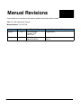
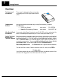
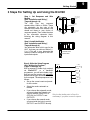
D3--HSC
High Speed Counter
Manual Number D3--HSC-M
WARNING
Thank you for purchasing automation equipment from PLCDirectä. We want your new DirectLOGICä automation
equipment to operate safely. Anyone who installs or uses this equipment should read this publication (and any other
relevant publications) before installing or operating the equipment.
To minimize the risk of potential safety problems, you should follow all applicable local and national codes that regulate
the installation and operation of your equipment. These codes vary from area to area and usually change with time. It is
your responsibility to determine which codes should be followed, and to verify that the equipment, installation, and
operation is in compliance with the latest revision of these codes.
At a minimum, you should follow all applicable sections of the National Fire Code, National Electrical Code, and the
codes of the National Electrical Manufacturer’s Association (NEMA). There may be local regulatory or government
offices that can also help determine which codes and standards are necessary for safe installation and operation.
Equipment damage or serious injury to personnel can result from the failure to follow all applicable codes and
standards. We do not guarantee the products described in this publication are suitable for your particular application,
nor do we assume any responsibility for your product design, installation, or operation.
If you have any questions concerning the installation or operation of this equipment, or if you need additional
information, please call us at 1--800--633--0405.
This publication is based on information that was available at the time it was printed. At PLCDirectä we constantly
strive to improve our products and services, so we reserve the right to make changes to the products and/or
publications at any time without notice and without any obligation. This publication may also discuss features that may
not be available in certain revisions of the product.
Trademarks
This publication may contain references to products produced and/or offered by other companies. The product and
company names may be trademarked and are the sole property of their respective owners. PLCDirectä disclaims any
proprietary interest in the marks and names of others.
Stage is a trademark of Koyo Electronics Industries Co., LTD. Texas Instruments is a registered trademark of Texas
Instruments, Inc. TI, TIWAY, Series 305, Series 405, TI305, and TI405 are trademarks of Texas Instruments, Inc.
Siemens and SIMATIC are registered trademarks of Siemens, AG. GE is a registered trademark of General Electric
Corporation. Series One is a registered trademark of GE Fanuc Automation North America, Inc. MODBUS is a
registered trademark of Gould, Inc. IBM is a registered trademark of International Business Machines. MS-DOS and
Microsoft are registered trademarks of Microsoft Corporation. Windows is a trademark of Microsoft Corporation.
OPTOMUX and PAMUX are trademarks of OPTO 22.
Copyright 1997, PLCDirectä Incorporated
All Rights Reserved
No part of this manual shall be copied, reproduced, or transmitted in any way without the prior, written consent of
PLCDirectä Incorporated. PLCDirectä retains the exclusive rights to all information included in this document.
1
Manual Revisions
If you contact us in reference to this manual, please include the revision number.
Title: DL--305 High Speed Counter
Manual Number: D3--HSC--M
Issue
Date
Effective Pages
Description of Changes
Original
7/95
Cover/Copyright
Contents 1--22
Back Cover
Original Issue
Rev. A
6/98
Entire Manual
Manual Revisions
Downsize to spiral
Rev. A
1
Table of Contents
Getting Started
Manual Overview . . . . . . . . . . . . . . . . . . . . . . . . . . . . . . . . . . . . . . . . . . . . . . . . . . . . . . . . . . . . . . . . . . . .
Introduction to High Speed Counters . . . . . . . . . . . . . . . . . . . . . . . . . . . . . . . . . . . . . . . . . . . . . . . . .
What is a High Speed Counter? . . . . . . . . . . . . . . . . . . . . . . . . . . . . . . . . . . . . . . . . . . . . . . . . . . . . .
Who Needs a High Speed Counter? . . . . . . . . . . . . . . . . . . . . . . . . . . . . . . . . . . . . . . . . . . . . . . . . .
Types of Counting . . . . . . . . . . . . . . . . . . . . . . . . . . . . . . . . . . . . . . . . . . . . . . . . . . . . . . . . . . . . . . . . .
Using Presets and Current Count . . . . . . . . . . . . . . . . . . . . . . . . . . . . . . . . . . . . . . . . . . . . . . . . . . . . .
What is a Preset and Current Count? . . . . . . . . . . . . . . . . . . . . . . . . . . . . . . . . . . . . . . . . . . . . . . . .
Using an Offset Value for Current Count . . . . . . . . . . . . . . . . . . . . . . . . . . . . . . . . . . . . . . . . . . . . . .
Positive Value Requirement . . . . . . . . . . . . . . . . . . . . . . . . . . . . . . . . . . . . . . . . . . . . . . . . . . . . . . . .
The HSC Outputs . . . . . . . . . . . . . . . . . . . . . . . . . . . . . . . . . . . . . . . . . . . . . . . . . . . . . . . . . . . . . . . . . . . .
External Outputs OUTPUT1 and OUTPUT2 . . . . . . . . . . . . . . . . . . . . . . . . . . . . . . . . . . . . . . . . . .
Two Modes of Controlling Outputs . . . . . . . . . . . . . . . . . . . . . . . . . . . . . . . . . . . . . . . . . . . . . . . . . . .
Output Logic Control . . . . . . . . . . . . . . . . . . . . . . . . . . . . . . . . . . . . . . . . . . . . . . . . . . . . . . . . . . . . . . .
Current Count Outputs in BCD . . . . . . . . . . . . . . . . . . . . . . . . . . . . . . . . . . . . . . . . . . . . . . . . . . . . . .
Status Flags (I/O Points) . . . . . . . . . . . . . . . . . . . . . . . . . . . . . . . . . . . . . . . . . . . . . . . . . . . . . . . . . . .
Counter Reset . . . . . . . . . . . . . . . . . . . . . . . . . . . . . . . . . . . . . . . . . . . . . . . . . . . . . . . . . . . . . . . . . . . . . . .
External Reset . . . . . . . . . . . . . . . . . . . . . . . . . . . . . . . . . . . . . . . . . . . . . . . . . . . . . . . . . . . . . . . . . . . .
Two Response Rates . . . . . . . . . . . . . . . . . . . . . . . . . . . . . . . . . . . . . . . . . . . . . . . . . . . . . . . . . . . . . .
General Specifications . . . . . . . . . . . . . . . . . . . . . . . . . . . . . . . . . . . . . . . . . . . . . . . . . . . . . . . . . . . . . . .
3 Steps For Setting Up and Using the D3-HSC . . . . . . . . . . . . . . . . . . . . . . . . . . . . . . . . . . . . . . . . .
2
3
3
3
3
4
4
4
4
5
5
5
5
5
6
7
7
7
8
9
Installation and Wiring
Installing the Module . . . . . . . . . . . . . . . . . . . . . . . . . . . . . . . . . . . . . . . . . . . . . . . . . . . . . . . . . . . . . . . .
Selecting a Slot for the HSC Module . . . . . . . . . . . . . . . . . . . . . . . . . . . . . . . . . . . . . . . . . . . . . . . . .
Selecting the Response Rate . . . . . . . . . . . . . . . . . . . . . . . . . . . . . . . . . . . . . . . . . . . . . . . . . . . . . . .
Inserting the Module in the Base . . . . . . . . . . . . . . . . . . . . . . . . . . . . . . . . . . . . . . . . . . . . . . . . . . . .
10
10
10
10
Wiring the Module . . . . . . . . . . . . . . . . . . . . . . . . . . . . . . . . . . . . . . . . . . . . . . . . . . . . . . . . . . . . . . . . . . .
General Considerations . . . . . . . . . . . . . . . . . . . . . . . . . . . . . . . . . . . . . . . . . . . . . . . . . . . . . . . . . . . .
Soldering the Wires to the Connector Block . . . . . . . . . . . . . . . . . . . . . . . . . . . . . . . . . . . . . . . . . . .
Wiring for UP/ DOWN Counting . . . . . . . . . . . . . . . . . . . . . . . . . . . . . . . . . . . . . . . . . . . . . . . . . . . . .
11
11
11
11
Encoder Wiring Diagram . . . . . . . . . . . . . . . . . . . . . . . . . . . . . . . . . . . . . . . . . . . . . . . . . . . . . . . . . . . . .
Output Wiring Diagram . . . . . . . . . . . . . . . . . . . . . . . . . . . . . . . . . . . . . . . . . . . . . . . . . . . . . . . . . . . . . .
Reset Wiring Diagram . . . . . . . . . . . . . . . . . . . . . . . . . . . . . . . . . . . . . . . . . . . . . . . . . . . . . . . . . . . . . . .
BCD Outputs . . . . . . . . . . . . . . . . . . . . . . . . . . . . . . . . . . . . . . . . . . . . . . . . . . . . . . . . . . . . . . . . . . . . . . . .
I/O Specifications . . . . . . . . . . . . . . . . . . . . . . . . . . . . . . . . . . . . . . . . . . . . . . . . . . . . . . . . . . . . . . . . . . .
12
13
14
15
16
ii
Table of Contents
Writing the Program
Writing the Program . . . . . . . . . . . . . . . . . . . . . . . . . . . . . . . . . . . . . . . . . . . . . . . . . . . . . . . . . . . . . . . . .
17
How to Enter Your Program: . . . . . . . . . . . . . . . . . . . . . . . . . . . . . . . . . . . . . . . . . . . . . . . . . . . . . . . .
Setup Procedure . . . . . . . . . . . . . . . . . . . . . . . . . . . . . . . . . . . . . . . . . . . . . . . . . . . . . . . . . . . . . . . . . .
Flow Diagram of SetupLogic . . . . . . . . . . . . . . . . . . . . . . . . . . . . . . . . . . . . . . . . . . . . . . . . . . . . . . . .
17
17
17
Setting Up the Counters . . . . . . . . . . . . . . . . . . . . . . . . . . . . . . . . . . . . . . . . . . . . . . . . . . . . . . . . . . . . .
Programming Conventions . . . . . . . . . . . . . . . . . . . . . . . . . . . . . . . . . . . . . . . . . . . . . . . . . . . . . . . . .
Preset and Current Count . . . . . . . . . . . . . . . . . . . . . . . . . . . . . . . . . . . . . . . . . . . . . . . . . . . . . . . . . .
Relationship Between Preset and Current Count . . . . . . . . . . . . . . . . . . . . . . . . . . . . . . . . . . . . . .
What Happens After the Counter Reaches the Upper Limit? . . . . . . . . . . . . . . . . . . . . . . . . . . . .
Overflow . . . . . . . . . . . . . . . . . . . . . . . . . . . . . . . . . . . . . . . . . . . . . . . . . . . . . . . . . . . . . . . . . . . . . . . . .
18
18
18
19
19
19
Setting Up the Outputs . . . . . . . . . . . . . . . . . . . . . . . . . . . . . . . . . . . . . . . . . . . . . . . . . . . . . . . . . . . . . .
How to Control The Outputs: . . . . . . . . . . . . . . . . . . . . . . . . . . . . . . . . . . . . . . . . . . . . . . . . . . . . . . . .
Flow Diagram of SetupLogic . . . . . . . . . . . . . . . . . . . . . . . . . . . . . . . . . . . . . . . . . . . . . . . . . . . . . . . .
Table 1: Status of Mode and Logic Controls in the Automatic Mode . . . . . . . . . . . . . . . . . . . . . .
Setting Mode and Output Logic Control . . . . . . . . . . . . . . . . . . . . . . . . . . . . . . . . . . . . . . . . . . . . . .
20
20
20
20
21
Putting It All Together -- Examples
Example 1: Activating both Outputs Automatically . . . . . . . . . . . . . . . . . . . . . . . . . . . . . . . . . . . . .
Example 2: Mixing Modes of Operation for Outputs . . . . . . . . . . . . . . . . . . . . . . . . . . . . . . . . . . . .
Example 3: Changing Presets On the Fly . . . . . . . . . . . . . . . . . . . . . . . . . . . . . . . . . . . . . . . . . . . . . .
22
23
24
D3--HSC
High-Speed Counter
In This Manual. . . .
— Getting Started
— Installation and Wiring
— Writing the Program
— Putting It All Together -- Examples
2
Getting Started
Overview
The Purpose of
this Manual
This manual is designed to allow you to setup
and install your D3--HSC High-Speed Counter
(HSC).
Supplemental
Manuals
Here are two additional manuals that you may find necessary or helpful:
User Manuals
D
DL305 User Manual
part number
D3--USER--M
D
DirectSoft Programming Software
part number
DA--DSOFT--M
Who Should Read
this Manual
If you need a High-Speed Counter for your DL305 PLC and you understand the
basics of installing and programming PLCs, this is the right manual for you.
Quality Technical
Manuals and
Technical Support
We strive to make our manuals the best in the industry, and we rely on your feedback
to let us know if we are reaching our goal. If you cannot find the solution to your
particular application, or, if for any reason you need additional assistance, please
call us at 800--633--0405. Our technical support group is glad to work with you in
answering your questions. They are available weekdays from 9:00 a.m. to 6:00
p.m. Eastern Time. You can also contact us on the worldwide web at:
http://www.plcdirect.com
(PLCDirect Web site for general info/file transfers)
You can also find a variety of support solutions at our 24--hour per day BBS at:
770--844--4209
If you find a problem with any of our products, services, or manuals, please fill out
and return the ’Suggestions’ card that came with this manual.
Getting Started
3
Introduction to High Speed Counters
What is a High
Speed Counter?
Who Needs a High
Speed Counter?
Literally, high speed counters count fast! The DL305 High Speed Counter (D3-HSC)
has its own microprocessor that asynchronously counts and accumulates the high
speed pulses. The D3-HSC will count pulses from sensors, encoders, switches, and
so on, at two different response modes. You can use its10 kHz mode when
measuring the fast pulses ( 500 Hz to 10kHz), or you can use the 500 Hz mode when
measuring pulses being transmitted at a much slower frequency (below 500 Hz).
Both frequencies require 50% duty cycle.
If you are using a DL305 system and
have an application that needs to count
pulses rapidly, then you are a prime
candidate for an HSC. In most
applications, the HSC counts pulses
being sent from encoders.
Encoders are used to emit pulses in
relation to a turning motor shaft. The
encoders emit a certain number of
pluses with each shaft rotation. By
counting the pulses, you can easily
determine the position of things being
controlled by the motors. The pulses are
counted at high speed, and are then
compared to a preset that you define in
your program. The results of this
comparison control the built-in HSC
outputs or can be used to perform
operations within your RLL program.
Types of Counting
DL305 System
OUTPUT1
2 outputs:
OUTPUT2
HSC
Encoder
An example application could be as follows: An encoder could be connected to a
motor shaft that is moving boards into position for cutting. An output (OUTPUT1)
could control the OFF and ON signal to a motor that advances the boards. Since the
same current count and preset can be setup to affect both outputs, you could use
OUTPUT2 to control the cutting blade.
The D3-HSC can do standard UP and DOWN counting. It cannot do quadrature
counting, and therefore cannot be used with a quadrature encoder. The UP/DOWN
input signals can come from standard 1--channel encoders. One channel is used for
UP counting and the other channel is used for DOWN counting.
Using 1 Encoder for UP Counting
INA
Using 1 Encoder for DOWN Counting
UP
INB
DWN
33
4
Getting Started
Using Presets and Current Count
What is a Preset
and Current Count?
High speed counters allow you to enter a target pulse count value (called the Preset
) that you can use to make some event (or events) happen. The event could be
turning on a lamp, starting a motor, tripping a switch--virtually anything. When the
HSC starts counting pulses the accumulated count is continuously being written to
the HSC’s memory. This value is referred to as the Current Count. In most
applications, when current count equals preset (C = P), the event or events will be
triggered. The D3--HSC will turn ON or OFF up to two external outputs when C = P.
You determine whether the outputs are turned ON or OFF when you write your
ladder logic. Actually with the D3--HSC you are given the option to automatically turn
outputs ON or OFF when C = P, or you can turn the outputs on manually at any time
regardless of the relationship between C and P. We’ll talk more about automatic and
manual operation on the next page.
Normal place to trigger
an event (C = P)
Preset Value
Pulse
Count
Time
Using an Offset
Value for Current
Count
You do not have to start your current count at zero when starting your high speed
counter. If you start at some number other than zero, this is called an “offset”. We’ll
show you how to enter the offset when we explain the setup procedure in greater
detail.
Positive Value
Requirement
When setting up the preset or current count offset value, you must use a positive
number between 0 and 9999. The D3--HSC does not understand negative numbers.
Getting Started
The HSC Outputs
External Outputs
OUTPUT1 and
OUTPUT2
In most applications, you need to take some type of action when the number of
pulses (current count) received equals your preset target (C=P).There are two
discrete external outputs (OUTPUT1 and OUTPUT2) for the D3--HSC. The outputs
are triggered by a combination of your ladder logic and/or the pulses received on the
count inputs of the HSC.
DL305 System
HSC
DL305
OUTPUT1
INA--UP
2 outputs:
OUTPUT2
Encoder A
Two Modes of
Controlling Outputs
You can control the two outputs of the D3-HSC by choosing one of two modes:
D
Automatic (Mode=1)----If you choose the automatic mode, then the current
count alone will determine when an output will change status (ON or OFF).
D
Manual (Mode=0)----If you choose to operate the outputs manually, then the
current count of the counter does not affect the outputs. Instead, you can use
the outputs just like any normal output, which means you control them with
your ladder logic program.
Output Logic Control The relationship between current count and preset controls the outputs, when in
Current Count
Outputs in BCD
automatic mode. However, there is an additional feature called Output Logic Control
that lets you choose how the outputs operate. For example, in one application you
may want the output to come on when current count equals preset (C=P). However,
in another application, you may want the output to go off when current count equals
preset (C=P). Fortunately, you can choose the method individually for each point.
Pages 18--19 explain this in more detail.
You cannot read the current count of the HSC by reading an internal register. This is
different from the HSC modules offered in the DL205 and DL405 families. However,
there are 16 outputs that can be connected to a display (or even an input module) to
show the current count in BCD. We’ll talk about this in a later section.
Example Interface for BCD Output of Current Count Value to LED Display
User--Supplied
Display Circuit
55
6
Getting Started
Status Flags
(Internal Relays)
In addition to the two external outputs (OUTPUT1 and OUTPUT2) and the BCD
outputs, the D3-HSC also will set several status flags (C < P, C = P, C > P and
Carry/Borrow) that are assigned to certain I/O points that you can use in your ladder
logic. These I/O points are internal to the HSC and have no outside connecting
points on the module connector.
Later, we’ll present a table that shows you what memory reference to use in your
ladder logic in order for the CPU to read the status of these flags. The numbers
referring to the status flag relays are uniquely determined by the base slot position
that you choose for your HSC.
Below is a diagram showing the internal and external I/O of the HSC.
HSC
Current
Count
BCD
Output
C<P
C=P
C>P
Output1
Carry/Borrow
Output2
Field Devices
Base Backplane
CPU
Getting Started
Counter Reset
External Reset
Two Response Rates
Once the pulses have been counted you need a way to reset the counter. There are
two options:
D
External Reset--You can reset the counter of the HSC externally via a device
connected to pins 6A and 6B on the front of the module. The wiring diagram
on Page 12 provides the electrical details. This can be a limit switch,
proximity switch, photoswitch, or virtually any field device that will provide a
logical high pulse (in the range of 3VDC to 7VDC) for a period of at least 100
milliseconds.
D
Internal Ladder Logic Reset-- You can also reset the counter by using the
proper sequence of commands in your ladder logic. You do this by entering a
new Current Count value, followed by entering a Preset Value in the same
scan cycle. We’ll show you how to do this in the back part of this manual
when we show you how to write logic for some specific applications.
There are two dip switches located on the
circuit board of the HSC----the one
marked SW2 (with the letters S and M
marking the switch positions) is for
matching up the responsiveness of the
reset switch with the counting rate. SW1
is for setting the counting rate.
Consequently, when you set the counting
rate on SW1 (either 500 Hz or 10 kHz),
you will want to set SW2 so that it
matches.
Position M= 500 Hz and Position S =
10kHz.
SW1
Set response
for counting
OPEN inputs
1 2
SW2
S
M Set response
for external
reset
77
8
Getting Started
General Specifications
Item
Specification
Counter
UP/DOWN Counter
Counter Speed
10 kHz maximum
Dip Switch Selectable Response Rates:
Either 10 kHz or 500 Hz (50% Duty Cycle)
Counter Inputs
1 Count UP Input
1 Count DOWN Input
Reset
External Reset Available
Count Value
Non-Retentive Upon Power Cycle
Counter Preset
Set by CPU Ladder Logic Program
Outputs
(External Points)
16-Outputs for BCD Display
Output1
Output2
Status Flags
(Internal Relays)
C < P Flag
C = P Flag
C > P Flag
Carry/Borrow Flag
Output Response
0.01 ms, maximum
Base Power Requirement
9V 70 mA, maximum
Weight
4.6 ounces (130 grams)
NOTE: The D3-HSC cannot perform quadrature counting. This module will not work
with a quadrature type encoder.
Getting Started
3 Steps For Setting Up and Using the D3-HSC
Step 1: Set Response and Wire
Module
(See “Installation and Wiring”,
Pages 8 through 14)
The
HSC
has
two
response
speeds--either 10kHz or 500Hz. These
are selectable via two sets of dip
switches on the side of the module. You
should set these to your choice of
response speeds. Then, solder the wires
to the removable connector block,
following the wiring diagram in this
manual.
Step 2: Install the Module
(See “Installation and Wiring”,
Pages 8 through 9)
You will decide which slot to use for the
HSC. You have your choice of Slots 0, 1,
2, or 3. This will, in turn, determine the
memory locations assigned to the HSC
inputs and outputs.
Set response
for counting
OPEN inputs
1 2
Removable
Connector
Block
S
M Set response
for external
reset
DL305
Choose a slot
for the HSC
Step 3: Write the Setup Program
C160
IO020
(See “Writing the Program”,
OUT RST
Pages 15 through 19)
C160
With a segment of ladder logic entered
IO110
SET
via DirectSOFT or a handheld
programmer, you will write ladder logic
IO111
SET
that sets up the counter and optionally
determines the logic and mode of control
IO112
SET
for the outputs. The setup sequence is as
follows:
IO113
SET
D
Set up the current count and preset
for the counter.
D
Select the mode--automatic or
manual
D
If you choose the automatic mode,
you must select the Output Logic
Control method (ON-to-OFF or
Only the first bullet point in Step 3 is
OFF-ON) for OUTPUT1 and
necessary if you plan to use no outputs.
OUTPUT2
D
If you choose the manual mode,
you must write the logic to control
OUTPUT1 and OUTPUT2 directly.
99
10
Installation and Wiring
Installing the Module
Selecting a Slot for
the HSC Module
The D3-HSC can occupy Slots 0,1, 2, or 3 of any DL305 base. The module will not
function in any other slots.The memory assignments for the HSC’s inputs and
outputs (to be used in your ladder logic) are affected by the slot you choose. Pages
17 through 19 of this manual show you the specific memory assignments for inputs
and outputs. For example, the following diagram is of a D3-08B 8-slot base. Notice
that the CPU slot has no number.
Slot No. 6 5 4 3 2 1 0
Example with
HSC in Slot 1
Selecting the
Response Rate
Base
Power Supply
DL305
As mentioned earlier, the response rate for counting is dip switch selectable. Also
the speed at which the reset input can be detected is selectable. These switches are
on the component side of the module’s internal circuit board. SW1 is at the top and
SW2 at the bottom. Use the table below to select the rate. If the pulses are being sent
at a rate higher than 500 Hz, then you need to choose the 10 kHz setting. Be aware
that the frequency response rate of SW1 must match that of SW2 if you plan to use
the external reset.
SW1
OPEN
1 2
S
SW2
Inserting the Module
in the Base
CPU
M
SW1
10 kHz
500 Hz
Counting Inputs:
Position 1
Position 2
OPEN
OPEN
CLOSED
CLOSED
S
Position
M
Position
SW2
External Reset
When inserting components into the base, align the PC board of the HSC module
with the grooves on the top and bottom of the base. Push the module straight into the
base until it is firmly seated in the backplane connector.
Align module to
slots in base and slide in
WARNING: Never connect or install a module into the base while the power is
applied. Failure to remove the power prior to the installation can result in
damage to the module, other installed modules, the power supply and/or the
CPU itself.
Installation and Wiring
11
11
Wiring the Module
General
Considerations
Consider the following guidelines when connecting the field wiring to the D3-HSC.
1. There is a maximum size wire the module can accept. We recommend that you
2.
3.
4.
5.
6.
7.
8.
9.
Soldering the Wires
to the Connector
Block
use wire that is no smaller than 22 AWG and no larger than 18 AWG.
Always use a continuous length of wire, do not combine wires to attain a desired
length.
Use the shortest possible cable length.
Use wire trays for routing where possible
Avoid running wires near high energy wiring.
Avoid running input wiring in close proximity to output wiring where possible.
To minimize voltage drops when wires must run a long distance , consider using
multiple wires for the return line.
Avoid running DC wiring in close proximity to AC wiring where possible.
Avoid creating sharp bends in the wires.
The D3-HSC is shipped with the connector block and snap-together wire cover
packaged separately. This block fits on the 32-pin male connector slot on the front of
the module. Before you connect it to the HSC, you may find it easier to solder the
wires that you will be connecting from the encoders, the external power supply, the
optional BCD outputs, the external reset, and two discrete outputs (OUTPUT1 and
OUTPUT2). Refer to the wiring diagram on the next few pages for details.
Be careful not to create cold solder joints or place so much solder on a connecting pin
that it shorts out against a neighboring pin. Make sure you refer to Page 13 for
connecting the BCD outputs correctly. Note which bit of the 16-bit word goes with the
each weighted position of the BCD value (4 bits per numeral). You don’t want to mix
up the bits; otherwise, you will get a current count number that is incorrect.
Take care also to position the wires while soldering so that the cover can be snapped
securely around the wires. The cover consists of two pieces. They are held together
by small screws and hex nuts. Two long-shaft thumb screws attach the cover
securely to the module as a final step.
WARNING: To minimize potential shock, turn off power to the I/O base and any
modules installed in the base before inserting or removing a module. Failure
to do so may result in potential injury to personnel or damage to the
equipment.
Wiring for UP/ DOWN On Page 10 of this manual you will be shown how to wire encoders for UP counting or
Counting
for DOWN counting. Different connecting pins are used for each task.
IMPORTANT: When one channel is counting (either UP or DOWN), the other
channel must be held high. If you are using only one encoder, tie the (+) connecting
pin for the unused input to the high (positive) side of the encoder’s power supply ;
and the (--) pin to the negative side.
12
Installation and Wiring
Encoder Wiring Diagram
B
DOWN Counting
A
16
Encoder
2
15
Jumper
14
13
+
12VDC
1
A
B
Pin No.
12
11
--
Unused encoder input
1A wired to positive.
Unused encoder input
1B wired to negative.
10
9
8
7
6
5
4
NOTE: There are two pairs of encoder connecting pins. 1A
and 1B are for UP counting and 2A and 2B are for DOWN
counting. You must hook your encoder to one set of pins.
The unused set of pins must have the (A) pin connected to
the positive side of the encoder supply, and the (B) pin
connected to the negative side.
UP Counting
Unused encoder input
2A wired to positive.
Unused encoder input
2B wired to negative.
3
2
2
1
B
A
Pin No.
HSC Connector
12VDC
Jumper
1
A
B
Pin No.
+
Encoder
Internal Circuitry
optoisolator
+
330 ohms
Internal circuits on logic side
of optoisolator
--
Internal circuit on field
side of optoisolator
To output of encoder
--
Installation and Wiring
13
13
Output Wiring Diagram
B
A
16
Load
15
B
14
A
16
13
12
Load
11
10
HSC Connector
9
8
5
7
6
4
5
3
V1+
V1-5 or 24 VDC
4
3
2
1
B
A
Pin No.
NOTE: Pins 3, 4 and 5 are internally connected. Any one of
these pins can be used for the supply wiring.
Internal Circuitry
V1+
Optoisolator
Load
16A
V1+
3A, 4A, or 5A
Internal circuits on logic side
of optoisolator
V1-Internal circuit on field
side of optoisolator
3B, 4B, or 5B
5 or 24 VDC
14
Installation and Wiring
Reset Wiring Diagram
B
A
16
15
14
13
12
11
10
HSC Connector
B
A
9
+
6
8
5 or 12 VDC
7
6
5
4
3
2
1
B
A
Pin No.
Internal Circuitry
optoisolator
+
330 ohms
Internal circuits on logic side
of optoisolator
Internal circuit on field
side of optoisolator
--
--
Installation and Wiring
15
15
BCD Outputs
The CPU cannot read the current count directly, but there are 16 BCD outputs for
driving a BCD display or connecting to a DC input module to read the current count
into the CPU. The 16-connecting points (7A&B thru 14A&B) are attached to the BCD
input of the drivers for visually displaying the BCD value or you can wire them to an
input module. Such a configuration is completely optional, and requires that you
supply the external devices. You determine the voltage level of these 16 points
through your choice of an external power supply with the positive side connected to
points 3A, 4A, 5A, and negative side connected to 3B, 4B, and 5B.
Example Interface for BCD Output of Current Count Value to LED Display
B
A
HSC Connector
16
Bit No.
15
15
14
14
13
12
13
12
11
11
10
10
9
9
8
8
6
V1
5
4
Note:
Pins 3, 4 and 5
are internally
connected.
8000
4000
2000
1000
Hundreds
800
400
200
100
Tens
2
+
1
6
80
5
4
40
20
10
3
2
1
0
3
Units
8
4
2
1
5 or 12 VDC
B
A
Pin No.
LEDs
Thousands
7
7
Internal
Power
Drivers
--
User--Supplied Display Circuit
BCD Output Circuit (For Interfacing Display Device or Input Module)
Sourcing
Negative
Logic
10K
V1+
V1+
10K
Photocoupler
Sinking
Load
Positive
Logic
Photocoupler
Load
V1--
V1--
16
Installation and Wiring
I/O Specifications
Input Specifications
Count Input
Reset Input
Minimum Input Pulse Width
25 ms
100 ms
Signal Direction
Falling Edge
ON
Power Source Voltage
12 VDC 10%
12 VDC 10%
ON Current
10--25 mA
10--25 mA
OFF Current
3 mA max.
3 mA max.
ON Voltage
7 V min.
7 V min.
OFF Voltage
3 V max.
3 V max.
BCD Output Specifications
Current Consumption
5 V ¦ 5%
12V ¦ 10%
10 mA max.
25 mA max.
1% max.
3% max.
0.1 mA
0.4 mA
Ripple
Output Current (source) (6.0 V)
External Output Specifications
Rating
Output Type
NPN Open Collector
Output Voltage
5--24 VDC
Output Current
0.3 A
Leakage Current
0.05 mA max.
17
17
Writing the Program
Writing the Program
How to Enter Your
Program:
You can write your PLC program by using a
computer with DirectSOFT programming
software, or using a handheld programmer
compatible with your particular model of
CPU.
Handheld
Programmer
HSC
DL305
Programming via
Computer
Setup Procedure
The HSC must be set up with your ladder logic in a specified manner. If you are using
the counters only (and not the external outputs), then you only have to worry about
setting up the counters:
D
Setup the Counters -- Your logic must setup a current count value (C) and a
preset value (P) in the same scan cycle. The order of execution must be
current count first and preset second. The values used for either C or P can
be any integer between 0 and 9999. A value must be entered--there are no
default values.
D
Flow Diagram of
SetupLogic
Setup the Outputs (Optional) -- If you plan to use the external outputs, you must
setup something called Output Mode and Output Logic Control for each of the two
outputs. These two settings will ultimately control the logic status (OFF or ON) and
the method for triggering each output.
Start
Setup Current Count
Setup Preset
Do you
want counting
only?
YES!
Stop!
No need to set
Mode or the
Logic Control
NO!
YES!
Do you
want the counter
to automatically
control the
output?
AUTOMATIC
(Mode=1)
What
output status
do you want
when C< P?
OFF!
Set Output
Logic=0
Output=ON
when C= P
and C> P
ON!
Set Output
Logic=1
Output=OFF
when C= P
and C> P
NO!
MANUAL
(Mode=0)
ON!
What
output status
do you want?
OFF!
Set Output
Logic=1
Set Output
Logic=0
Output=ON
Immediately
Output=OFF
Immediately
18
Writing Your Program
Setting Up the Counters
Programming
Conventions
As mentioned earlier, you can use either a handheld programmer or DirectSOFT to
enter your ladder logic. The examples we will be giving in this section of the manual
are specific to DirectSOFT. We will, however, where necessary point out some
subtle differences for the handheld programmer. When setting up your counters, you
will be using the following conventions:
D
D
D
Preset and Current
Count
Instructions -- You will not be using the normal counter box when setting up the
HSC. While in DirectSOFT, if you use hot key F7 and examine the list of boxes
available, you will find that one of them is called HSC. This is the box that you use in
your ladder logic for setting up the HSC. If you are using the handheld programmer
for the DL305, you will use the conventional CNT key (followed by the appropriate
counter number) in order to do the setup.
Registers or Constants -- In order to setup the current count and preset in
your counters, you can either enter constant values directly (i.e. K125) or you
can point to any user-register (i.e. R400 ) where the values are stored. This is
entirely up to you. We have used the direct reference with a constant in all of
our examples.
Activating the Setup -- the counter begins counting pulses as soon as the CPU
enters the RUN mode and the setup logic is scanned. You can use any type of
permissive contact to trigger the setup logic. The setup logic only has to be scanned
one time to setup the preset and the current count starting point. Therefore, it is
important to trigger the setup logic with a one--shot. (See the example below as to
how this is done.) If you don’t use a one-shot, the current count and preset setup will
be executed as long as the permissive contact is on. (It will look like the counter isn’t
working properly, but in reality your program is simply loading a current count on
every scan!)
Shown below is a table with the counter numbers that you will enter either in your
HSC box (when using DirectSOFT) or following your CTR command when using the
handheld programmer. Notice that the counter used depends on the module
location in the base.
Counter Setup
Slot 0 Cntr
Slot 1 Cntr
Slot 2 Cntr
Slot 3 Cntr
Current Count
CT100
CT102
CT104
CT106
Preset
CT101
CT103
CT105
CT107
Example: The following ladder logic initializes an HSC in Slot 0 with a preset value of 125
and a current count of 0. Notice the OUT RST instruction. In the DL305 instruction set, the
OUT RST is a one-shot, similar to the PD (positive differential) instruction of the DL205 and
DL405 families.
Start Setup
IO120
C160
OUT RST
C160
HSC
CT100
K0
HSC
CT101
K125
Setup One--Shot
Setup Current
Count
Load 0 into current count counter
Setup Preset
Load 125 into
preset counter
Writing the Program
Relationship
Between Preset and
Current Count
19
19
The relationship between current count and preset will change as your program runs
and the HSC continues to count pulses. You can monitor the status of C<P, C=P, and
C>P by checking certain I/O points. Each of the three flags have I/O points assigned
to them for storing the status of each. The addresses associated with these points
changes according to which slot you have used for the HSC. You can use the I/O
points for these flags to trigger events inside your RLL program.
Counter Status
Slot 0
Slot 1
Slot 2
Slot 3
C >P
IO000
IO010
IO020
IO030
C=P
IO001
IO011
IO021
IO031
C<P
IO002
IO012
IO022
IO032
Example: The following ladder logic will turn ON an indicataor lamp when C = P for an HSC
in Slot2.
Setup of HSC precedes this section of code.
C=P
IO021
IO150
OUT
Turn ON indicator lamp.
What Happens After The upper limit for the counter is 9999. If your ladder logic has been written so that
the Counter Reaches the counter continues to count past C=P and eventually reach a current count of
the Upper Limit?
9999, the counter will stop counting pulses when it reaches the upper limit. It does
not wrap around to zero. It is instead in an “overflow” status.
Overflow
The I/O point assigned to the Overflow function (current count greater than 9999
range) of the HSC can also be monitored by your RLL to either report the status or
trigger an event. The address associated with the I/O point changes according to
HSC slot position and is shown in the following table:
Counter Overflow
Slot 0
Slot 1
Slot 2
Slot 3
Count > 9999
IO003
IO013
IO023
IO033
Example: The following ladder logic will sound an alarm if the current count
exceeds 9999. This example assumes the HSC is in Slot 0.
Setup of HSC precedes this section of code.
Overflow relay
IO003
IO140
OUT
Turn On Alarm connected at IO140
20
Writing Your Program
Setting Up the Outputs
How to Control The
Outputs:
You use your ladder logic to select the way that the HSC outputs operate. You will
use your logic to turn ON or OFF certain internal I/O points that control what are
called Output Mode and Output Logic Control. By controlling the mode and logic
for Outputs1 and 2, we are able to determine when the outputs turn ON or OFF. The
flow diagram shown below explains the thought process for setting the mode and
logic control to determine the status of the outputs. For example, if you choose to
operate OUTPUT1 in the automatic mode, and you want to have the output ON
when current count is less thant preset (C < P), then you will want to set Output1
Mode = 1 and set Output1 Logic Control = 1.
Flow Diagram of
SetupLogic
YES!
Do you
want the counter
to automatically
control the
output?
AUTOMATIC
(Mode=1)
What
output status
do you want
when C< P?
Set Output
Logic=0
Set Output
Logic=1
Output=ON
when C= P
MANUAL
(Mode=0)
ON!
ON!
OFF!
NO!
Output=OFF
when C= P
What
output status
do you want?
OFF!
Set Output
Logic=1
Set Output
Logic=0
Output=ON
Immediately
Output=OFF
Immediately
Table 1
It may be also useful to look at the relationship between the Output Mode and Output
Status of Mode and
Logic control and the external outputs for C < P and C = P using a table.
Logic Controls in the
Automatic Mode
Output 1 Mode Output 1 Logic
Output 1
Output 1
Control
C<P
C=P
1
0
OFF
ON
1
1
ON
OFF
Output 2 Mode
Output 2 Logic
Control
Output 2
C<P
Output 2
C=P
1
0
OFF
ON
1
1
ON
OFF
NOTE: When in the Automatic Mode (Output Mode = 1), the output will assume the
state determined by the output logic control as soon as the CPU is placed into the
Run Mode.
Writing the Program
21
21
Setting Mode and
The table shown below will help you determine the appropriate internal I/O points for
Output Logic Control selecting the Mode and Output Logic Control associated with the two outputs of the
HSC. Remember the HSC can go into Slots 0, 1, 2 or 3. The numbers associated
with the I/O points change depending on which slot you have selected.
CPU Output Reference
Slot 0
Slot 1
Slot 2
Slot 3
Output 1 Mode
IO100
IO110
IO120
IO130
Output 1 Logic Control
IO101
IO111
IO121
IO131
Output 2 Mode
IO102
IO112
IO122
IO132
Output 2 Logic Control
IO103
IO113
IO123
IO133
Example: The following example shows how to set up an HSC installed in Slot 1 to
automatically control the outputs. You want both outputs to be ON when the PLC is
placed in RUN (C<P), but turn OFF when C=P. The table shows IO110--IO113 for
Slot1. If we follow the flow chart, we see that we need to turn ON IO110--IO113, which
selects the automatic mode for both outputs and the C=P operation to go from ON to
OFF.
Start Setup
IO020
C160
OUT RST
C160
IO110
SET
IO111
SET
Setup One--Shot
Output 1 Mode= 1 (Automatic)
Output 1 Logic Control = 1
IO112
SET
Output 2 Mode= 1 (Automatic)
IO113
SET
Output 2 Logic Control= 1
When using the automatic mode (as shown above), the state of Output 1 Logic
Control and Output 2 Logic Control determines the state of Output1 and Output2
until C = P. So in the above example, both outputs will turn ON as soon as the PLC
enters RUN mode. These outputs will remain ON until enough pulses have been
counted for current count to equal preset (C = P).
The example below, uses the RST command to set the Mode to manual and it uses
the OUT command to control the Logic Controls for the two outputs IO21 and IO22.
Start Setup
IO020
C160
C160
OUT RST
IO110
RST
IO111
RST
IO21
IO112
OUT
IO22
IO113
OUT
Setup One--Shot
Output 1 Mode= 0 (Manual)
Output 2 Mode= 0 (Manual)
IO21 and IO22 are inputs from a disctrete input module installed in Slot 2.
Output1 will follow the status of IO21.
Output2 will follow the status of IO22.
22
Putting It All Together
Example 1:
Activating both Outputs Automatically
As you know from reading earlier
pages, the HSC module can go in slots
0,1, 2, or 3. In this program, we are
assuming that the HSC module has
been placed in Slot 1. This means that
the counters (HSC boxes) in your
program would be designated as
CT102 and CT103 (See Page 16). The
Output Mode and Output Logic control
are assigned I/O points 110 through
113 (See Page 19).
We are using IO0 and C160 as a
one-shot to start this setup.The
one-shot enables the two HSC boxes,
CT102 and CT103 for one scan. This
initializes the preset value to 20 and
the current count to 0.
C160 also turns ON IO111 and IO113,
enabling the Automatic Mode for both
outputs. This means when each output
will turn ON or OFF is solely dependent
on the current count and preset. When
C = P, OUTPUT1 and OUTPUT2 will
be activated. Whether this means
either output turns ON or OFF,
depends on how you have set the
Output Logic Control in each case.
Here you see that we have set the
logic of both to 1. So, this means that
the output will be ON when C < P and
turn OFF when C = P.
Start Switch
C160
OUT RST
IO0
One-Shot
C160
HSC
CT102
K0
HSC
CT103
K20
C160
IO111
SET
Setup One--Shot
Setup Current
Count
Load 0 into current count counter
Setup Preset
Load 20 into
preset counter
Set Output1 Mode=Automatic (1)
IO113
SET
Set Output2 Mode=Automatic(1)
IO110
SET
Set Output1 Logic = 1
IO112
SET
Set Output2 Logic = 1
The core of your program goes here.
END
Putting It All Together
23
23
Example 2:
Mixing Modes of Operation for Outputs
In this example, we are illustrating how
you can use the manual and automatic
modes for controlling outputs in the
same program. We have decided to
control OUTPUT1 automatically, and
to control OUTPUT2 manually. This
could be a cut-to-length application
where OUTPUT1 advances a board
toward a saw for a preset number of
pulses recorded by the HSC. OUTPUT2 controls the cutting operation.
We will assume the HSC module is in
Slot 1.
When C = P, OUTPUT1 is turned OFF.
At the same time, relay C162 turns on
a timer (T600). When T600 times out,
we turn ON OUTPUT2 by setting
IO112. In our board cutting example,
this could mean that a saw is activated
by OUTPUT2. The point being made
here is that manual control of an
output or outputs operates
independently from the status of
preset and current count.
Start Switch
IO0
One-Shot
C160
HSC
CT102
K0
HSC
CT103
K20
C160
C=P
IO11
Turns ON when C = P
C162
T600
In the Manual Mode, the relationship
of current count compared to preset
does not automatically affect the output. In the example shown here, we
have used an internal status flag relay
IO11 (C=P) to start a timer. When the
timer times out(1 second), we turn ON
OUTPUT2 by setting IO112. This is
done to insure the board has stopped
moving before we start the cut.
C160
OUT RST
Setup Current
Count
Load 0 into current count counter
Setup Preset
Load 20 into
preset counter
IO111
SET
Set Output1 Mode = Automatic (1)
IO113
RST
Set Output2 Mode=Manual (0)
IO110
SET
Set Output1 Logic = 1
C162
SET
TMR
T600
K10
IO112
SET
C162
RST
Cut Complete
IO1
Setup One--Shot
IO112
RST
Set internal relay
C162 when current
Startcount
timer equals
that will
preset.
run for one second.
When T600 times
out, turn ON
OUTPUT2 and reset
the timer.
When cut is complete, turn OFF
OUTPUT2.
The core of your program goes here.
END
24
Putting It All Together
Example 3: Changing Presets On the Fly
WARNING: The application shown below changes the counter’s preset value while
the program is executing. Under some conditions (explained in a moment), this
causes OUTPUT1 and OUTPUT2 to turn ON for approximately 1 millisecond as
soon as preset is changed. This condition occurs only if the external outputs are OFF
when the change is initiated, and you are in the automatic mode of control. This
could result in unsafe or unpredictable results if the field device connected to the
outputs sees this momentary ON signal. To prevent this, include a segment in your
ladder logic that switches the operating mode of the HSC to manual before the
preset is changed. The example below illustrates how this is done.
In this example, we are illustrating how
you can change the preset value “on the
fly”. This means you are changing the
preset while the program is still running.
Although we are only showing the logic for
controlling OUTPUT1, the same method
could be used to affect both outputs.
We have placed the HSC in Slot 1 for this
example. It can, of course, go into any Slot
0 through 3. We will assume at the point in
in your program where this logic starts, the
process has been running with a Preset
that had been entered in earlier ladder
logic not shown here. At the point this
ladder logic is executed, the counter has
already been counting pulses and
comparing them against the previous
Preset.
This part of the program uses an MCS and
MCR instruction to load a new Current
Count and Preset value. The logic
between MCS and MCR will only execute
when the MCS rung has power flow.
With this example, the process is started
via IO002. When energized, C161 is
latched in the ON state. C161 also enables
the MCS. C161 resets IO111, putting the
HSC in Manual Mode. The only other rung
that executes during this first scan is the
rung that causes C161 to turn ON C162.
On the second scan through the logic
inside the MCS/MCR, since C162 is now
ON, CT102 loads a new Current Count of
0 and CT103 writes a new Preset of 200.
C162 will one-shot C165, which puts the
HSC back into autmatic mode and resets
IO110. It also disables the MCS/MCR.
Load New Preset
IO002
Disable Load
C165
C161
OUT
Configure HSC
Configure HSC
C161
Configure HSC
C161
MCS
Configure HSC
C161
IO111
RST
Load HSC Current Count
C162
HSC
CT102
Set Output1 Mode =0 (manual)
Current Count
Value Set to 0
K0
Load HSC Preset
C162
HSC
CT103
Preset Value Set
to 200
K200
C162
C165
OUTRST
Configure HSC
C161
C162
OUT
MCR
Disable Load
C165
Disable Load Using One-shot
Load HSC Current
Count and Preset
End logic under MCS
and MCR Control
IO111
SET
Set Output1 Mode =1 (automatic)
IO110
RST
END
Output 1 Logic Control=0