1
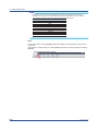
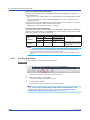
User’s
Manual
SMARTDAC+ STANDARD
Hardware Configurator
User’s Manual
IM 04L61B01-02EN
1st Edition
Introduction
Notes
Trademarks
Revisions
This manual explains how to use SMARTDAC+ STANDARD Hardware Configurator. To
ensure correct use, please read this manual thoroughly before beginning operation.
• The contents of this manual are subject to change without prior notice as a result of
continuing improvements to the software’s performance and functions.
• Every effort has been made in the preparation of this manual to ensure the accuracy of its
contents. However, should you have any questions or find any errors, please contact your
nearest YOKOGAWA dealer.
• Copying or reproducing all or any part of the contents of this manual without
YOKOGAWA’s permission is strictly prohibited.
• The TCP/IP software of this product and the document concerning the TCP/IP software
have been developed/created by YOKOGAWA based on the BSD Networking Software,
Release 1 that has been licensed from University of California.
• vigilantplant and SMARTDAC+ are registered trademarks of Yokogawa Electric
Corporation.
• Microsoft, Windows, and Internet Explorer are either registered trademarks or trademarks
of Microsoft Corporation in the United States and/or other countries.
• Adobe and Acrobat are registered trademarks or trademarks of Adobe Systems
Incorporated.
• Pentium is a trademark of Intel Corporation in the United States and/or other countries.
• Company and product names that appear in this manual are registered trademarks or
trademarks of their respective holders.
• The company and product names used in this manual are not accompanied by the
registered trademark or trademark symbols (® and ™).
December 2012
1st Edition
1st Edition: December 2012 (YK)
All Right Reserved, Copyright © 2012, Yokogawa Electric Corporation
IM 04L61B01-02EN
i
Software License Agreement
IMPORTANT - PLEASE READ CAREFULLY BEFORE INSTALLING OR USING:
THANK YOU VERY MUCH FOR SELECTING SOFTWARE OF YOKOGAWA ELECTRIC CORPORATION (“YOKOGAWA”) PROVIDED BY DOWNLOADING FROM
YOKOGAWA’S WEB SITE, OR THE RECORDING MEDIUM (collectively, “Software Product”). BY INSTALLING OR OTHERWISE USING THE SOFTWARE PRODUCT, YOU
AGREE TO BE BOUND BY THE TERMS AND CONDITIONS OF THIS AGREEMENT. IF YOU DO NOT AGREE, DO NOT INSTALL NOR USE THE SOFTWARE PRODUCT.
1. Scope
This Agreement applies to the Software Product and associated documentation of Yokogawa. Unless otherwise provided by Yokogawa, this Agreement applies to the updates
and upgrades of the Software Product which may be provided by Yokogawa.
Software product: SMARTDAC+ STANDARD Hardware Configurator
2. Grant of License
2.1 Subject to the terms and conditions of this Agreement, Yokogawa hereby grants to you a non-exclusive and non-transferable right to use the Software Product for your internal
operation use,
2.2 Unless otherwise agreed or provided by Yokogawa in writing, the following acts are prohibited:
a) to reproduce the Software Product, except for one archival copy for backup purpose, which shall be maintained with due care subject to this Agreement;
b) to sell, lease, distribute, transfer, pledge, sublicense, make available via the network or otherwise convey the Software Product or the license granted herein to any other
person or entity;
c) to use the Software Product on any unauthorized computer via the network;
d) to cause, permit or attempt to dump, disassemble, decompile, reverse-engineer, or otherwise translate or reproduce the Software Product into source code or other human
readable format, or to revise or translate the Software Product into other language and change it to other formats than that in which Yokogawa provided;
e) to cause, permit or attempt to remove any copy protection used or provided in the Software Product; or
f) to remove any copyright notice, trademark notice, logo or other proprietary notices or identification shown in the Software Product.
2.3 Any and all technology, algorithms, know-how and process contained in the Software Product are the property or trade secret of Yokogawa or licensors to Yokogawa.
Ownership of and all the rights in the Software Product shall be retained by Yokogawa or the licensors and none of the rights will be transferred to you hereunder.
2.4 You agree to maintain the aforementioned property and trade secret of Yokogawa or licensors and key codes in strict confidence, not to disclose it to any party other than your
employees, officers, directors or similar staff who have a legitimate need to know to use the Software Product and agreed in writing to abide by the obligations hereunder.
2.5 Upon expiration or termination of this Agreement, the Software Product and its copies, including extracts, shall be returned to Yokogawa and any copies retained in your
computer or media shall be deleted irretrievably. If you dispose of media in which the Software Product or its copy is stored, the contents shall be irretrievably deleted.
2.6 The Software Product may contain software which Yokogawa is granted a right to sublicense or distribute by third party suppliers, including affiliates of Yokogawa (“Third
Party Software”). If suppliers of the Third Party Software (“Supplier”) provide special terms and conditions for the Third Party Software which differ from this Agreement, the
special terms and conditions separately provided by Yokogawa shall prevail over this Agreement. Some software may be licensed to you directly by Supplier.
2.7 The Software Product may contain open source software (“OSS”), for which the special terms and conditions separately provided by Yokogawa shall take precedence over
this Agreement.
3. Restrictions on Application
3.1 Unless otherwise agreed in writing between you and Yokogawa, the Software Product is not intended, designed, produced or licensed for use in relation to aircraft operation
or control, ship navigation or marine equipment control, or ground facility or device for support of the aforesaid operation or control, or for use in relation to rail facility, nuclear
related facility, radiation-related equipment, or medical equipment or facility, or under any other circumstances which may require high safety standards.
3.2 If the Software Product is used for the abovementioned purposes, neither Yokogawa nor assumes liability for any claim or damage arising from the said use and you shall
indemnify and hold Yokogawa, Supplier, their affiliates, subcontractors, officers, directors, employees and agents harmless from any liability or damage whatsoever, including
any court costs and attorney’s fees, arising out of or related to the said use.
4. Limited Warranty
4.1 The Software Product shall be provided to you on an “as is” basis at the time of delivery, Yokogawa shall disclaim all of the warranties whatsoever, express or implied, and all
liabilities therefrom. If any physical defect is found on the recording medium not later than twelve (12) months from delivery, Yokogawa shall replace such defective medium
free of charge, provided that the defective medium shall be returned to the service office designated by Yokogawa at your expense within the said twelve (12) months. THIS
LIMITED WARRANTY PROVIDED IN THIS CLAUSE IS IN LIEU OF ALL OTHER WARRANTIES OF ANY KIND WHATSOEVER AND YOKOGAWA HEREBY DISCLAIMS
ALL OTHER WARRANTIES RELATING TO THE SOFTWARE PRODUCT, WHETHER EXPRESSED OR IMPLIED, INCLUDING WITHOUT LIMITATION, ANY IMPLIED
WARRANTIES OF MERCHANTABILITY, FITNESS FOR ANY PARTICULAR PURPOSE, NON-INFRINGEMENT, QUALITY, FUNCTIONALITY, APPROPRIATENESS,
ACCURACY, RELIABILITY AND RECENCY. IN NO EVENT SHALL YOKOGAWA WARRANT THAT THERE IS NO INCONSISTENCY OR INTERFERENCE BETWEEN
THE SOFTWARE PRODUCT AND OTHER SOFTWARE NOR SHALL BE LIABLE THEREFOR. The warranty provisions of the applicable law are expressly excluded to the
extent permitted.
4.2 At the sole discretion of Yokogawa, Yokogawa may upgrade the Software Product to the new version number (“Upgrade”) and make it available to you at your expense or
free of charge as Yokogawa deems fit. In no event shall Yokogawa be obliged to upgrade the Software Product or make the Upgrade available to you.
4.3 Certain maintenance service may be available for some types of Software Product at Yokogawa’s current list price. Scope and terms and conditions of the maintenance
service shall be subject to those separately provided by Yokogawa. Unless otherwise provided in Yokogawa catalogues or General Specifications, maintenance services
will be available only for the latest version and the immediately preceding version. In no event will service for the immediately preceding version be available for more than 5
years after the latest version has been released. In addition, no service will be provided by Yokogawa for the Software Product which has been discontinued for more than 5
years. Notwithstanding the foregoing, maintenance service may not be available for non-standard Software Product. Further, in no event shall Yokogawa provide any service
for the Software Product which has been modified or changed by any person other than Yokogawa.
ii
IM 04L61B01-02EN
Software License Agreement
5. Infringement
5.1 If you are warned or receive a claim by a third party that the Software Product in its original form infringes any third party’s patent (which is issued at the time of delivery of
the Software Product), trade mark, copyright or other intellectual property rights (“Claim”), you shall promptly notify Yokogawa thereof in writing.
5.2 If the infringement is attributable to Yokogawa, Yokogawa will defend you from the Claim at Yokogawa’s expense and indemnify you from the damages finally granted by the
court or otherwise agreed by Yokogawa out of court. The foregoing obligation and indemnity of Yokogawa shall be subject to that i) you promptly notify Yokogawa of the Claim
in writing as provided above, ii) you grant to Yokogawa and its designees the full authority to control the defense and settlement of such Claim and iii) you give every and all
necessary information and assistance to Yokogawa upon Yokogawa’s request.
5.3 If Yokogawa believes that a Claim may be made or threatened, Yokogawa may, at its option and its expense, either a) procure for you the right to continue using the Software
Product, b) replace the Software Product with other software product to prevent infringement, c) modify the Software Product, in whole or in part, so that it become noninfringing, or d) if Yokogawa believes that a) through c) are not practicable, terminate this Agreement and refund you the paid-up amount of the book value of the Software
Product as depreciated.
5.4 Notwithstanding the foregoing, Yokogawa shall have no obligation nor liability for, and you shall defend and indemnify Yokogawa and its suppliers from, the Claim, if the
infringement is arising from a) modification of the Software Product made by a person other than Yokogawa, b) combination of the Software Product with hardware or software
not furnished by Yokogawa, c) design or instruction provided by or on behalf of you, d) not complying with Yokogawa’s suggestion, or e) any other causes not attributable to
Yokogawa.
5.5 This section states the entire liability of Yokogawa and its suppliers and the sole remedy of you with respect to any claim of infringement of a third party’s intellectual property
rights. Notwithstanding anything to the contrary stated herein, with respect to the claims arising from or related to the Third Party Software or OSS, the special terms and
conditions separately provided for such Third Party Software or OSS shall prevail.
6. Limitation of Liability
6.1 EXCEPT TO THE EXTENT THAT LIABILITY MAY NOT LAWFULLY BE EXCLUDED IN CONTRACT, YOKOGAWA SHALL NOT BE LIABLE TO ANY PERSON OR LEGAL
ENTITY FOR LOSS OR DAMAGE, WHETHER DIRECT, INDIRECT, SPECIAL, INCIDENTAL, CONSEQUENTIAL OR EXEMPLARY DAMAGES, OR OTHER SIMILAR
DAMAGES OF ANY KIND, INCLUDING WITHOUT LIMITATION, DAMAGES FOR LOSS OF BUSINESS PROFITS, BUSINESS INTERRUPTION, LOSS OR DESTRUCTION
OF DATA, LOSS OF AVAILABILITY AND THE LIKE, ARISING OUT OF THE USE OR INABILITY TO USE OF THE SOFTWARE PRODUCT, OR ARISING OUT OF ITS
GENERATED APPLICATIONS OR DATA, EVEN IF ADVISED OF THE POSSIBILITY OF SUCH DAMAGES, WHETHER BASED IN WARRANTY (EXPRESS OR IMPLIED),
CONTRACT, STRICT LIABILITY, TORT (INCLUDING NEGLIGENCE), OR ANY OTHER LEGAL OR EQUITABLE GROUNDS. . If the Software Product delivered by
Yokogawa is altered, modified or combined with other software or is otherwise made different from Yokogawa catalogues, General Specifications, basic specifications,
functional specifications or manuals without Yokogawa’s prior written consent, Yokogawa shall be exempted from its obligations and liabilities under this Agreement or law.
6.2 Any claim against Yokogawa based on any cause of action under or in relation to this Agreement must be given in writing to Yokogawa within three (3) months after the cause
of action accrues.
7. Export Control
You agree not to export or provide to any other countries, whether directly or indirectly, the Software Product, in whole or in part, without prior written consent of Yokogawa.
If Yokogawa agrees such exportation or provision, you shall comply with the export control and related laws, regulations and orders of Japan, the United States of America,
and any other applicable countries and obtain export/import permit and take all necessary procedures under your own responsibility and at your own expense.
8. Audit; Withholding
8.1 Yokogawa shall have the right to access and audit your facilities and any of your records, including data stored on computers, in relation to the use of the Software Product
as may be reasonably necessary in Yokogawa’s opinion to verify that the requirements of this Agreement are being met.
8.2 Even after license being granted under this Agreement, should there be any change in circumstances or environment of use which was not foreseen at the time of delivery
and, in Yokogawa’s reasonable opinion, is not appropriate for using the Software Product, or if Yokogawa otherwise reasonably believes it is too inappropriate for you to
continue using the Software Product, Yokogawa may suspend or withhold the license provided hereunder.
9. Assignment
If you transfer or assign the Software Product to a third party with Yokogawa’s prior written consent, you shall expressly present this Agreement to the assignee to ensure
that the assignee comply with this Agreement, transfer all copies and whole part of the Software Product to the assignee and shall delete any and all copy of the Software
Product in your possession irretrievably. This Agreement shall inure to the benefit of and shall be binding on the assignees and successors of the parties.
10. Termination
Yokogawa shall have the right to terminate this Agreement with immediate effect upon notice to you, if you breach any of the terms and conditions hereof. Upon termination of
this Agreement, you shall promptly cease using the Software Product and, in accordance with sub-clause 2.5, return or irretrievably delete all copies of the Software Product,
certifying the same in writing. Clauses 2.4 and 2.5, 3, 5, 6 and 11 shall survive any termination of this Agreement.
11. Governing Law; Disputes
This Agreement shall be governed by and construed in accordance with the laws of Japan.
Any dispute, controversies, or differences which may arise between the parties hereto, out of, in relation to or in connection with this Agreement (“Dispute”) shall be resolved
amicably through negotiation between the parties based on mutual trust. Should the parties fail to settle the Dispute within ninety (90) days after the notice is given from either
party to the other, the Dispute shall be addressed in the following manner:
(i) If you are a Japanese individual or entity, the Dispute shall be brought exclusively in the Tokyo District Court (The Main Court) in Japan.
(ii) If you are not a Japanese individual or entity, the Dispute shall be finally settled by arbitration in Tokyo, Japan in accordance with the Commercial Arbitration Rules of
the Japan Commercial Arbitration Association. All proceedings in arbitration shall be conducted in the English language, unless otherwise agreed. The award of arbitration
shall be final and binding upon both parties, however, each party may make an application to any court having jurisdiction for judgment to be entered on the award and/or for
enforcement of the award.
12. Miscellaneous
12.1 This Agreement supersedes all prior oral and written understandings, representations and discussions between the parties concerning the subject matter hereof to the extent
such understandings, representations and discussions should be discrepant or inconsistent with this Agreement.
12.2 If any part of this Agreement is found void or unenforceable, it shall not affect the validity of the balance of the Agreement, which shall remain valid and enforceable according
to its terms and conditions. The parties hereby agree to attempt to substitute for such invalid or unenforceable provision a valid or enforceable provision that achieves to the
greatest extent possible the economic, legal and commercial objectives of the invalid or unenforceable provision.
12.3 Failure by either party to insist on performance of this Agreement or to exercise a right when entitled does not prevent such party from doing so at a later time, either in relation
to that default or any subsequent one.
End of document
IM 04L61B01-02EN
iii
How to Use This Manual
Structure of the Manual
This manual contains the following three chapters.
Chapter
Title and Description
1
2
Before Using the Product
Provides an overview of Hardware Configurator. It also explains the PC system requirements, how to start the software,
the screen configuration, and the menus.
Creating Setup Data
3
Troubleshooting
Explains how to display, create, edit, save, and print setup data as well as how to control the GX/GP using this software.
Provides a list of errors ane messages.
Scope of This Manual
This manual does not explain the basic operations of your PC’s operating system. For this
information, read the Windows user’s guide or related materials.
Conventions Used in This Manual
Unit
K
k
Notes
WARNING
CAUTION
Note
Denotes 1024. Example: 768K (file size)
Denotes 1000.
Improper handling or use can lead to injury to the user or damage to
the instrument. This symbol appears on the instrument to indicate that
the user must refer to the user’s manual for special instructions. The
same symbol appears in the corresponding place in the user’s manual
to identify those instructions. In the manual, the symbol is used in
conjunction with the word “WARNING” or “CAUTION.”
Calls attention to actions or conditions that could cause serious or fatal
injury to the user, and precautions that can be taken to prevent such
occurrences.
Calls attention to actions or conditions that could cause light injury
to the user or cause damage to the instrument or user’s data, and
precautions that can be taken to prevent such occurrences.
Calls attention to information that is important for the proper operation
of the instrument.
Reference Item
Reference to related operation or explanation is indicated after this
mark.
Example: section 4.1
Conventions Used in the Procedural Explanations
Bold characters Indicates character strings that appear on the screen.
Example: Volt
Procedure
Carry out the procedure according to the step numbers. All procedures
are written under the assumption that you are starting operation at the
Explanation
beginning of the procedure, so you may not need to carry out all the
steps in a procedure when you are changing the settings.
The explanation section describes limitations and related information
about the operation.
iv
IM 04L61B01-02EN
How to Use This Manual
Images
The images used in this manual may differ from those that actually appear in the software.
Such differences do not affect the procedural explanation.
Products That This Manual Covers
Product
SMARTDAC+ STANDARD Hardware Configurator
Version
Up to R.1.01.xx
Revision History
Edition
1
IM 04L61B01-02EN
Explanation
New edition
v
Blank
Contents
1
Introduction............................................................................................................................................ i
Software License Agreement.................................................................................................................ii
How to Use This Manual.......................................................................................................................iv
2
3
Chapter 1 Before Using the Product
1.1
1.2
1.3
1.4
Overview of Hardware Configurator.....................................................................................1-1
1.1.1
1.1.2
Hardware Configurator Features.............................................................................................1-1
Installation and Version Updating............................................................................................1-1
PC System Requirements....................................................................................................1-2
1.2.1
1.2.2
1.2.3
1.2.4
Hardware.................................................................................................................................1-2
Operating System...................................................................................................................1-2
Web Browser...........................................................................................................................1-3
Other Operating Conditions....................................................................................................1-3
5
Window and Menus..............................................................................................................1-4
6
Starting and Closing Hardware Configurator....................................................................... 1-7
7
1.3.1
1.3.2
1.3.3
1.4.1
1.4.2
1.4.3
Window and Menu Configuration............................................................................................1-4
Menu Operation and Basic Workflow......................................................................................1-5
Workflow.................................................................................................................................1-6
Starting the Software...............................................................................................................1-7
Setting the Display Language and HTTP Port Number..........................................................1-8
Closing the Software...............................................................................................................1-9
Chapter 2 Creating Setup Data
2.1
2.2
2.3
2.4
2.5
2.6
2.7
2.8
Creating New Setup Data....................................................................................................2-1
2.1.1
Creating a New File.................................................................................................................2-1
Displaying Setup Data..........................................................................................................2-4
2.2.1
IM 04L61B01-02EN
8
9
Opening a File.........................................................................................................................2-4
Editing Setup Data...............................................................................................................2-6
10
Saving Setup Data.............................................................................................................2-19
11
2.3.1
2.3.2
2.3.3
2.4.1
Editing Settings.......................................................................................................................2-6
Editing and Manipulating Values.............................................................................................2-7
Selecting a Range and Copying and Pasting........................................................................ 2-11
Saving a Setup Data File......................................................................................................2-19
Receiving and Sending Setup Data................................................................................... 2-21
2.5.1
2.5.2
2.5.3
2.5.4
Receiving Setup Data...........................................................................................................2-21
Sending Setup Data..............................................................................................................2-22
Sending User Settings..........................................................................................................2-23
Changing the GX/GP User Settings via Communication......................................................2-23
Controlling the Recorder....................................................................................................2-26
2.6.1
2.6.2
Starting and Stopping Recording and Computing.................................................................2-26
Viewing the Recorder Hardware Information........................................................................2-27
12
App
Initializing Setup Data........................................................................................................2-29
2.7.1
2.7.2
Viewing and Changing the System Configuration.................................................................2-29
Initializing Setup Data...........................................................................................................2-29
Printing Setup Data............................................................................................................2-30
2.8.1
Setting the Print Options.......................................................................................................2-30
Chapter 3 Troubleshooting
3.1
4
Errors and Messages...........................................................................................................3-1
vii
Index
Blank
Chapter 1 Before Using the Product
Overview of Hardware Configurator
1.1.1
Hardware Configurator Features
1
Before Using the Product
1.1
2
SMARTDAC+ STANDARD Hardware Configurator is a PC software application for creating
setup data for the GX/GP recorder.
You can use it to create, edit, save, and print setup data.
You can also use it to exchange data with a recorder and control a recorder via
communication.
Web-based Offline Application
3
4
You can use a Web browser (Internet Explorer) on your PC to create and edit setup data.
You only need this software and a browser; you do not have to configure communication
parameters.
5
Creating and Editing Setup Data
You can create new setup data by specifying the model and options.
You can also edit existing setup data.
6
Saving and Loading Setup Data
You can save the data that you create to your PC and load setup files that have been saved
on your PC.
Sending and Receiving Setup Data
7
8
You can send setup data to and receive data from a recorder via communication.
Printing Setup Data
9
You can print setup data.
Controlling Recorders
10
You can start and stop recording or computing on the GX/GP via communication.
Retrieving Information from Recorders
You can retrieve information from a recorder via communication.
1.1.2
11
Installation and Version Updating
Download the latest installer from YOKOGAWA's website to install and update the software.
From the Help menu, you can view the software version information and access the link to
the website.
Note
• Close all other software applications before installing this software.
• To reinstall the software, uninstall the current software first.
• The “Countries/regions except Japan” selection dialog box appears during installation. Select
the country that you will use the software in.
• Standard Hardware Configurator uses HTTP port 34443 to communicate with the Web browser.
If this port is already in use by another application, you will not be able to start Hardware
Configurator even if you install it.
Corrective action: section 1.4
IM 04L61B01-02EN
1-1
12
App
Index
1.2
PC System Requirements
1.2.1
Hardware
PC
A PC running Windows XP, Windows Vista, or Windows 7
CPU and Main Memory
When Using Windows XP
Intel Pentium 4, 3 GHz or faster x64 or x86 processor. At least 2GB of RAM.
When Using Windows Vista
Intel Pentium 4, 3 GHz or faster x64 or x86 processor. At least 2GB of RAM.
When Using Windows 7
32-bit edition: Intel Pentium 4, 3 GHz or faster x64 or x86 processor. At least 2GB of RAM.
64-bit edition: Intel Pentium 4, 3 GHz or faster x64 processor. At least 2GB of RAM.
Hard Disk
Free space of at least 100 MB (depending on the amount of data, you may need more disk
space). NTFS recommended.
CD-ROM Drive
A CD-ROM drive compatible with the OS
Mouse
A mouse compatible with the OS
Display
A display that is compatible with the OS, that has a resolution of 1024×768 or higher, and
that can show 65,536 colors (16-bit, high color) or more.
Communication Board
To perform RS-232 communication, use a Windows compatible COM port (COM1, COM2,
COM3, or COM4).
To perform RS-422/RS-485 communication, connect a converter to the RS-232 port.
To perform Ethernet communication, you need a Windows-compatible Ethernet card. The
TCP/IP protocol must also be installed.
Printer
A Windows-compatible printer. A printer driver for the Windows system is required.
1.2.2
Operating System
OS
Windows XP
Windows Vista
Windows 7
1-2
Edition
Home Edition SP3 (excluding 64-bit editions)
Professional SP3 (excluding 64-bit editions)
Home Premium SP2 (excluding 64-bit editions)
Business Edition SP2 (excluding 64-bit editions)
Home Premium SP1 (32- or 64-bit edition)
Professional SP1 (32- or 64-bit edition)
IM 04L61B01-02EN
1.2 PC System Requirements
1.2.3
1
Web Browser
Version
Internet Explorer 6 or Internet Explorer 8
2
Note
• The Web browser that Hardware Configurator uses to display information is limited to Internet
Explorer (IE). If IE is not installed on your PC, an error will appear when you start Hardware
Configurator.
• IE versions other than the specified versions and other Web browsers are not supported.
1.2.4
Before Using the Product
Compatible Browser
Windows Internet Explorer
Java runtime Ver. 1.6
3
4
Other Operating Conditions
To view the user’s manual of this software, you need to use Adobe Reader 7 or later by
Adobe Systems (the latest version is recommended).
5
6
7
8
9
10
11
12
App
Index
IM 04L61B01-02EN
1-3
1.3
Window and Menus
1.3.1
Window and Menu Configuration
Hardware Configurator’s menu consists of the main menu, submenu, and file name display
area, as shown below.
Main menu (tab)
Submenu
File name display
Setup item names
Content
selection tree
Content area
Setup items
Show/hide button
Split bar
Copy and Paste buttons
Main Menu and Submenu
The main menu is tabular. Click a tab to activate it, and the submenu will switch accordingly.
The following table shows the menu items and their descriptions.
Main Menu
Setting
Operation
System
Option
Help
1-4
Submenu
New
Open
Save
Save As
Receive Settings
Send Settings
Send User Settings
Print Window
Start Recording
Stop Recording
Start Computing
Stop Computing
Hardware Info.
System Config.
Initialize
Display
Port No.
Instruction Manual
Version
Web to update
What You Can Do
Create a new setup data file.
Load a setup file from a PC.
Overwrite the file.
Save a new file to the PC.
Receive the GX/GP setup data.
Send the current setup data to the GX/GP.
Send only the user settings to the GX/GP via communication.
Open a window used to print setup data.
Start GX/GP recording.
Stop GX/GP recording.
Start GX/GP computing.
Stop GX/GP computing.
Receive and display the GX/GP status and option information.
View and change the system configuration.
Initialize the current setup data.
Specify the display option (language) of Hardware
Configurator.
Specify the port number of Hardware Configurator.
View the user’s manual.
View the Hardware Configurator version.
Visit the Website to download the latest version of Hardware
Configurator.
IM 04L61B01-02EN
1.3 Window and Menus
1
File Name Display
Before Using the Product
The setup file name is displayed in this area.
A specific file name or “New File” will be displayed.
2
A specific file name will be displayed under the following conditions.
• When a specific file is loaded and displayed
• When a file is saved using the Save As command
3
“New File” will be displayed under the following conditions.
• When Hardware Configurator starts
• When you click New
• When a connection is established with a recorder and the setup is received
4
Content Selection Tree
The content selection tree is used to select the items (edit items) you want to edit.
When you click an item in the content selection tree, the items displayed in the content area
(right side) change accordingly.
Content Area
5
6
The content area displays setup item details.
It displays the settings for the item selected in the content selection tree.
Immediately after Hardware Configurator starts, this area shows channel settings. If there
are no channel settings, this area shows display settings.
7
Split Bar
You can use the split bar to change the window layout.
Drag the split bar to change the panel width of the content selection tree area and content
area. Click the show/hide button in the center to show and hide the content selection tree.
8
Copy and Paste Buttons
9
Menu Operation and Basic Workflow
10
Procedure
11
The Copy and Paste buttons are used to copy and paste settings when you edit setup items.
1.3.2
The basic procedure for using Hardware Configurator is shown below.
For more details, see chapter 2, “Creating Setup Data.”
1
2
3
4
5
6
7
IM 04L61B01-02EN
Start Hardware Configurator.
12
Click a main menu tab (Setting, Operation, System, or Option).
Select a submenu item (New, Open, Start Recording, Stop Recording, etc.).
App
Perform operations in the displayed dialog box.
To edit settings, select a title in the content selection tree. Edit the displayed settings.
Process the setup data file that you created or edited by selecting appropriate
commands (Save, Send Settings, etc.) from the main menu and submenu.
Close Hardware Configurator.
1-5
Index
1.3 Window and Menus
1.3.3
Workflow
The features and workflow of Hardware Configurator are illustrated below.
Sec. 1.4
Start
Display window
New
Display setup data
Sec. 2.1
System
configuration
Receive and
display data
Sec. 2.2
Control the recorder
Sec. 2.5
Configure comm.
Edit?
Sec. 2.6
Sec. 2.5
Yes No
Receive data
Start recording, start computing,
Stop recording, stop computing,
View hardware information
Select the setup contents to edit
Edit the content area
Sec. 2.3
Save file
Sec. 2.4
Send setup data?
Yes
Configure comm.
Send data
Sec. 2.5
No.
Initialize data?
Yes
Initialize
Sec. 2.7
No
Print?
Yes
Sec. 2.8
No
End
1-6
Print
Sec. 1.4
IM 04L61B01-02EN
Starting and Closing Hardware Configurator
1.4.1
Starting the Software
1
2
Procedure
1
From the Start menu, select All Programs - SMARTDAC+ STANDARD - Hardware
Configurator.
Before Using the Product
1.4
The first time Hardware Configurator starts after installation, the Windows
Security Alert dialog box appears (the figure below is the dialog box for
Windows XP). Click Unblock.
3
4
5
6
7
8
Hardware Configurator starts, and the following window appears.
Close button
9
10
11
12
App
Index
Note
• Hardware Configurator will not start if Internet Explorer is not installed.
• The default settings are the system configuration of the GX20.
IM 04L61B01-02EN
1-7
1.4 Starting and Closing Hardware Configurator
System Configuration on the First Startup
The table below shows the default system configuration.
Details on system configuration: section 2.1
Item
Value
Model
GX20
Version
R1.01.01
Module
AI module (GX90XA-10-U2)
Option
No options
If the Default HTTP Port Number Is Already in Use (Port number conflict)
If the default port number (34443) is already in use by other type of communication when
Hardware Configurator starts for the first time, it will not be able to start. If this happens,
change the port number by following the procedure below.
1. Start Windows Task manager. (Press Ctrl+Alt+Del, and click Task Manager. Or, click
Ctrl+Shift+Esc.)
2. End the process “ndxserver.exe.”
3. Start the command prompt with system administrator privileges.
4. Move to the software installation directory, and use the following command-line
command to change the port number.
C:\installation directory>ndxserver /portno=xxxxx
where xxxxx is an unused port number. Specify an unused port number in the range of
34443 to 65535.
Note
To change the port number to a different number after starting the software, follow the procedure in
the next section (section 1.4.2).
1.4.2
Setting the Display Language and HTTP Port Number
You can set the display language to English or Japanese.
Procedure
1
2
On the main menu, click the Option tab.
On the submenu, click Display.
The Display Option dialog box appears.
3
1-8
Click the Language arrow, and select from the list.
The display language changes to the selected language.
IM 04L61B01-02EN
1.4 Starting and Closing Hardware Configurator
1
You can specify the HTTP port number for using the Web browser from this software.
1
2
Before Using the Product
Procedure
2
On the main menu, click the Option tab.
On the submenu, click Port No.
3
4
The Port No. dialog box appears.
5
6
7
3
Enter the port number (in the range of 34443 to 65535).
8
Note
To activate the new port number, restart the software.
The software will continue to use the old port number until you restart the software.
1.4.3
9
Closing the Software
10
Procedure
1
Close Internet Explorer by clicking the Close button or by clicking Exit on the File
menu.
11
Note
If you change the setup data, the changes are stored and will appear the next time you start the
software.
12
App
Index
IM 04L61B01-02EN
1-9
Blank
Chapter 2 Creating Setup Data
2.1
Creating New Setup Data
1
2.1.1
Creating a New File
2
This section explains how to use SMARTDAC+ STANDARD Hardware Configurator to
create a new data file for configuring various GX functions.
Creating Setup Data
3
Procedure
1
Start Hardware Configurator.
4
The setup window appears.
5
6
7
8
9
2
On the main menu, click the Setting tab and then New.
10
Click the Setting tab and then New.
11
A confirmation message may be displayed that asks whether you want to save the current setup
file that is open.
12
App
Index
3
IM 04L61B01-02EN
To save the file, click Yes; otherwise, click No.
2-1
2.1 Creating New Setup Data
If you click Yes, a dialog box for saving the file (see the figure below) appears.
How to save files: section 2.4
If you select No, the System Config. dialog box, shown in step 4, appears.
4
Set the system configuration. Select the GX options and the current module
configuration.
Click to
select a module.
When you have
changed the items
click OK.
Select whether these
options are available.
5
2-2
To not change, click Cancel.
After you set the items, click OK.
The system configuration is loaded, and setup items based on the configuration are created.
IM 04L61B01-02EN
2.1 Creating New Setup Data
6
1
Edit the setup items in the new window to create the setup data.
How to edit setup items:
“2.3 Editing Setup Data”
2
Note
3
Creating Setup Data
If you reconfigure the system configuration, the setup items that you have edited up to that point
will be initialized. To save these items, click Yes in step 2.
4
5
6
7
8
9
10
11
12
App
Index
IM 04L61B01-02EN
2-3
2.2
Displaying Setup Data
2.2.1
Opening a File
This section explains how to load and display an existing setup data file that has been saved
to a PC.
Procedure
1
2
Start Hardware Configurator.
The setup window appears.
On the main menu, click the Setting tab and then Open.
The Open dialog box* appears.
* If there are many files in the folder, it may take some time to display the list.
Current location
Click to move to
a higher level folder.
Double-click to open the folder.
2-4
Open the folder containing setup data files.
IM 04L61B01-02EN
2.2 Displaying Setup Data
3
1
Select the setup data file (.GNL extension) that you want to open,* and click Open.
2
Creating Setup Data
3
4
Displays the file name
of the selected file
5
6
Select the setup data file you want to open.
Click Open.
7
The data is loaded.
The name of the
loaded file appears.
8
9
10
11
12
Note
The maximum file path length (including the file name) is 256 characters. If this limit is exceeded,
an error will occur. Pay attention to the hierarchical depth and file name length.
App
Index
IM 04L61B01-02EN
2-5
2.3
Editing Setup Data
2.3.1
Editing Settings
This section explains how to use Hardware Configurator to edit recorder's setup data (.gnl
extension).
The setup data editing and display features are the same as those of the Web application on
the recorder itself.
In addition, the setup items of this software are the same as those on the recorder.
Therefore, this section will only cover typical operations and the unique features of this
software.
Setup item details:
ection 3.1 in the Models GX10/GX20/GP10/GP20 Paperless Recorder
S
User’s Manual (IM 04L51B01-01EN).
Procedure
1
Display the file that you want to edit on the Setting tab.
Setup item names
Content
selection tree
Content
area
2
From the content selection tree, which is on the left side of the window, select the
name of the setup item you want to edit. (This example will show how to set DI
channels.)
Click +
to expand
the tree
and show the
next level.
Selecting an item
changes the content
display.
Content selection tree
(setup item names)
When you select a name, the relevant setup items are loaded in the content area, which is on the
right.
Note
Loading takes a certain amount of time, so a “processing” icon may appear. While this icon is
displayed, you cannot perform any operations.
2-6
IM 04L61B01-02EN
2.3 Editing Setup Data
3
1
Edit the channel settings.
Edit the setup items in the content area.
2
Creating Setup Data
3
4
Channel number
1 line = 1 channel
The DI channel setup window
is loaded, and the items
in the content area change.
5
Scroll right to view
more setup items.
Note
6
• The changes you make in the content area are retained in the software.
• The software is designed to operate offline, so all items in the content area can be changed.
2.3.2
7
Editing and Manipulating Values
Input Controls and Dialog Boxes
When you edit settings on this software, input controls and dialog boxes shown in the table
below appear for you to select or enter values.
Control Type
Text box
Display Example
Setup Procedure
Enter text or numbers.
Check box
When the check box is selected, the setting is “On”
or enabled.
List box
Click the arrow, and select from the list that appears.
Option buttons
Click to select.
Dialog Box Type
Channel selection button
Display Example Setup Procedure
Operation 1
To configure a specific channel such as an I/O
Step 1
channel, click a channel number to specify the
channel you want.
Color selection
Operation 1
Click a color on the color selection palette in the
Step 2
dialog box. You can also enter the RGB values to
specify any color.
Add channel
Operation 2
When specifying multiple channels such as
when editing a display group, click a channel
number button to add the channel to the channel
configuration. The added channel is displayed as a
character string.
Data selection
Operation 3
When specifying the internal switch or other item,
click the displayed character string such as the
switch number. (Same as channel selection.)
Special dialog box (calibration Operation 4
A dialog box for editing calibration correction values.
correction)
Enter the correction value directly.
Examples of representative editing operations that show the above dialog boxes is provided
on the next page.
From the content selection tree, select the setup item that you want to edit, and edit the
setup items that appear. In general, you can click a channel or data string to edit settings.
IM 04L61B01-02EN
2-7
8
9
10
11
12
App
Index
2.3 Editing Setup Data
Operation 1
1
Set the channel range.
Click here (▼) to show
the available values.
Enter values within
the selectable range.
Click to display the
Channel selection
dialog box (see below).
This example shows how to set the reference channel for a difference calculation. Click the
channel number under Reference channel.
The Channel selection dialog box appears.
Clicking a number applies
the output destination
and closes the dialog box.
Select from the channels that are
displayed as a result of module detection.
To not change or not set,
click Cancel to return.
2
Show or hide by channel type
(when multiple channel types
are available).
Scroll to the right, and set all necessary items.
Select this check box to enable.
Enter a character string.
Click to open the Color selection dialog box (step 3).
3
If you want to change the alarm mark color, click a color.
The color selection dialog box appears.
To create a user-defined
color, enter numbers.
Select a
color.
2-8
IM 04L61B01-02EN
2.3 Editing Setup Data
1
Operation 2
Add channel
2
This example shows how to assign channels to group 1. On the menu tree, click
Display settings and then Group settings. Under Channel set, click the channel
number.
Select this check
box to enable.
Creating Setup Data
3
4
Click to open the Add channel box (see the figure below).
The Add channel dialog box appears.
5
Channel
configuration
character String
Select channel
number check boxes
to add to the group.
6
7
Selected
channels
8
9
Show or hide channels.
Click OK to apply the settings to the configuration screen.
10
Operation 3
Data selection
11
This example shows how to set the alarm output destination. Click a number under
Output No.
The data selection dialog box appears.
12
Click a switch
number to apply
the output destination,
and return to the
configuration window.
App
Index
To not change or not set, click Cancel to return.
Note
• When the maximum number of selectable channels is reached, you will no longer be able to
select additional channels.
• On dialog boxes that show check boxes and option buttons, you can select a range.
How to select a range: “2.3.3 Selecting a Range and Copying and Pasting”
IM 04L61B01-02EN
2-9
2.3 Editing Setup Data
Operation 4
Special Dialog Box for Calibration Correction
This example shows how to edit calibration correction for AI channels. Under
calibration, click Linearizer input/output.
Select the calibration
correction mode.
Select the number of set points.
Click to open the Special dialog box (step below).
The Calibration correction dialog box appears.
Calibration correction
set points
Click OK to save the changes.
Editing an input position causes the value
to be checked against the upper and lower
limits and the value to be corrected.
Editing an output position
causes the value to be
checked against the upper
and lower limits.
Note
• If you enter a value in any input position in the Calibration correction dialog box, the value
is checked against the upper and lower limits and against the values of other positions and
corrected.
If you enter a value in any output position, the value is only checked against the upper and
lower limits. For details on calibration correction, see the Models GX10/GX20/GP10/GP20
Paperless Recorder User’s Manual (IM 04L51B01-01EN).
• The items and available settings that appear in the configuration window vary depending on
the hardware system configuration. If an item that you want to edit does not appear, check the
option and module configuration.
How to set the system configuration: section 2.1
2-10
IM 04L61B01-02EN
2.3 Editing Setup Data
2.3.3
1
Selecting a Range and Copying and Pasting
This software enables you to select a range of setup items to edit them, copy them, and
paste them.
This section explains how to select a range of items and how to use the Copy, Paste, and
Tool buttons.
Selecting a Range
Creating Setup Data
3
Procedure
1
2
To select a line, click an item name.
4
The example below is for Display settings - Trend settings - List type.
5
Click the line name.
6
7
8
9
10
The line is selected.
2
To select multiple lines, drag the cursor and release the mouse at the last line you
want to select.
11
12
App
Drag across
the line names
to select
multiple lines.
Index
Multiple lines are selected.
Note
When selecting a range, you cannot select multiple lines one by one. You cannot select columns
individually.
IM 04L61B01-02EN
2-11
2.3 Editing Setup Data
Copying the Selected Range and Pasting
Procedure
1
To copy the selected range, click the Copy button, which is located in the lower right of
the window. You can also press Ctrl+C on the keyboard.
When the range is copied to the Clipboard, the color of the range changes as shown below.
2
3
You can paste the contents of the Clipboard to an Excel spreadsheet or a text file. The
figure below shows an example in which the contents are copied to cell A1 of an Excel
spreadsheet.
When pasting to an Excel spreadsheet, check the format of the cell that you are
pasting to.
The pasted contents can be edit on Excel or a text editor.
Edit the values in the B column in Excel.
4
5
6
The edit contents can be pasted back to the setup items. Copy the edit results from the
Excel spreadsheet. Copy not just the values but also the item names in row A.
Select the paste range in the configuration window. Make the paste range the same as
the range of the copied data (the number of lines).
Paste the data. Click the Paste button, which is located in the lower right of the
window. You can also press Ctrl+V on the keyboard.
The edit results from the Excel spreadsheet is pasted to the configuration window.
2-12
IM 04L61B01-02EN
2.3 Editing Setup Data
Note
1
Selecting a Range of Channels Whose Types Are Different and Copying and
Pasting Them
The example below is an AI channel configuration window.
Procedure
1
2
3
Creating Setup Data
• Depending on the format of the Excel cells that you are pasting to, the values may change when
you paste the contents from the Clipboard. For example, if the format is set to Number, “0001”
will change to “1”. You can prevent pasted values from being automatically corrected by setting
Number to Text in the Format Cells dialog box of the Excel sheet that you want to paste to.
• If the values cannot be pasted as they are to the Excel sheet even with the settings above, we
recommend that you use a text editor for copying and pasting.
• If the values that you edit with Excel or a text editor are outside the setting range, when you
paste the data back to the configuration window of the software, the values will be corrected in
the same way as when you enter values directly.
4
5
Select a range of channels as shown below.
6
7
8
Click the name of the line to select the entire line.
Drag down to select multiple lines.
2
9
Copy the channel information (lines).
10
11
12
Press Ctrl+C, or click Copy to copy the cells.
3
Paste to different channels.
App
Index
Select the cells to paste to. Press Ctrl+V, or click Paste to paste to the cells.
IM 04L61B01-02EN
2-13
2.3 Editing Setup Data
The example below shows the configuration window that appears when you select Display
settings - Group settings - Channel set.
Procedure
1
Select a range of channels as shown below.
Click a label in a cell to select a single cell.
Drag to select a rectangular area.
Selection can be made across different setup item blocks.
2
While holding down Ctrl, click any of the check boxes in the selected range, or click the
On/Off button to select or clear all the check boxes in the selected range.
Click while holding down Ctrl, or click On/Off to
select the check boxes in the selected range at once.
All check boxes in the selected area are selected.
Click again to clear all the check boxes.
2-14
IM 04L61B01-02EN
2.3 Editing Setup Data
3
1
The contents in the selected range can be pasted to other cells.
2
Creating Setup Data
3
4
Select the cells to copy from, and press Ctrl+C to copy.
5
6
7
Select the cell to paste to and drag to select a range.
8
9
10
Press Ctrl+V to paste.
When the maximum number of selectable channels is reached,
no more check boxes can be selected.
11
Note
• When you attempt to copy and paste values, Internet Explorer may show the message “Do you
want to allow this webpage to access your clipboard?” Click Allow access to enable the copy
and paste feature of this software. If you click Don’t allow, you will not be able to use the copy
and paste feature.
• If the cells whose check box is selected (on) reaches the maximum selectable number, cells
whose check boxes are unselected become unavailable, and you will not be able to paste to
them. You cannot paste to cells that do not have check boxes.
• Pasting is not possible to character strings that cannot be edited or passwords (concealed
character strings).
• When option buttons or list boxes are selected, only the selected character strings can be
copied and pasted.
IM 04L61B01-02EN
2-15
12
App
Index
2.3 Editing Setup Data
Explanation
The configuration windows of this software can be classified into three window types.
First is the list type, as in the Trend settings window. Second is the table type, as in the AI
channel settings window. Third is the check box sheet type, as in the Channel set window
of Group settings. The table below shows the differences in how you edit items for each
window type.
Window
Type
List type
Table type
Check box
sheet type
2-16
Selectable Range
Selection Method
Selection
Cancellation
Method
• By lines.
Click the name of
Click a location other
• Multiple lines across the line to select the than a line name
different setup items
entire line.
and within the setup
can be selected.
Drag across the
item edit area.
names of lines to
select multiple lines.
Click a location other
• One or multiple lines. Click the name of
the line to select the than the line name.
entire line.
Drag across the
names of lines to
select multiple lines.
• By cells.
Click a label in a cell
• A rectangular region to select a single
can be selected.
cell.
Drag the cursor
diagonally to select
a rectangular area.
Selection can
be made across
different setup item
blocks.
Click an area within
the check sheet
without holding the
Ctrl key.
Limitations
Multiple lines cannot
be selected one by
one.
Columns cannot be
selected individually.
If you click a cell
in a different line,
the selection of
previously selected
cells will be cleared.
• If the cells that
are On reaches the
maximum selectable
number, cells whose
check boxes are not
selected become
unavailable.
IM 04L61B01-02EN
2.3 Editing Setup Data
1
Editing Using Tool Buttons
On table type configuration windows, you can use the tool buttons that are shown at the
bottom of each table. Each tool button is assigned a function. You can use them to edit items
collectively.
The available types of tool buttons are Initialize, Paste to all lines, Increment, Minimize/
Maximize, and Change all.
In the operation example below, the Paste to all tool button is used to set the Type of all
selected channels to the same value.
3
Creating Setup Data
Tool button types and functions: See the table on the next page.
2
4
Procedure
1
On the table type configuration window (the AI channel settings configuration window
in this example), select the lines that contain the data that you want to copy.
CH0001 is selected.
5
Data to copy
6
Select the line
to copy from.
7
Paste destination
2
8
Drag the cursor to the last line that you want to assign the same type.
CH0001 to CH00004 are selected.
9
10
11
Drag until the last line you want to paste the same data to.
3
12
Click the Past to all button on the tool bar.
App
Index
Click the Paste to all tool button.
The type of CH0002 to CH0004 is set to Volt.
Note
• When you use the tool button to paste data, the values are automatically corrected in the same
way as when you enter values directly.
• Tool buttons are unavailable when no cells are selected (except for the Change all button).
IM 04L61B01-02EN
2-17
2.3 Editing Setup Data
The table below shows the different tool button types and their functions.
Button
Past to all
Function
Pastes the value in the first selected line to all other lines.
Initialize
• For numeric input
Pastes numbers to all selected lines by auto-incrementing the least
significant digit, based on the number in the first selected line.
• For character string input
Pastes the character string of the first line appended with autoincremented sequence numbers to all selected lines.
If the character string of the first selected line ends with a number,
this number will be used as the first sequence number. If the
character string of the first selected line ends with a character, the
sequence number 1 is appended to the character string of the first
selected line.
Initializes the values of the selected lines to their defaults.
Increment
2-18
Icon
Minimize
Sets the values of the selected lines to their minimum values.
Maximize
Sets the values of the selected lines to their maximum values.
Change all
• For check boxes
Switches the check box values of the selected lines at once.
If all the check boxes of the selected lines are selected, they are
cleared. If they are cleared, they are selected.
• For line name columns
Selects or unselects all lines in the table.
IM 04L61B01-02EN
2.4
Saving Setup Data
1
2.4.1
Saving a Setup Data File
2
Procedure
3
This section explains how to save a setup data file to your PC.
Creating Setup Data
1
On the main menu, click the Setting tab and then Save As.
4
5
6
7
The Save As dialog box appears.
The first time you open this dialog box, Folder will be set to My Documents. The subsequent
times you open the dialog box, Folder will show the last location that you opened or save to.
Current location
8
Display the directory.
Move to a higher level folder.
9
Create a folder.
10
11
12
Double-click to open the folder.
2
App
Specify the folder to save to, enter the file name, and click Save.
If a file with the same name exists in the folder, an overwrite confirmation message will appear.
Click OK or Cancel.
Enter the file name.
Enter a comment.
Click to save.
If you click OK, the setup data file (.gnl extension) will be saved to the specified folder.
IM 04L61B01-02EN
2-19
Index
2.4 Saving Setup Data
Note
• The maximum file path length (including the file name) is 256 characters. If this limit is
exceeded, an error will occur. Pay attention to the hierarchical depth and file name length.
• The following characters cannot be used in file names or folder names.
Prohibited characters Name
/
Slash
><
Inequality signs
:
Colon
?
Question mark
"
Double quotation
'
Single quotation
\
Backslash
*
Asterisk
|
Pipe
;|
Semicolon
• You can enter up to 50 characters for the comment.
Save
On the main menu, click the Setting tab and then Save to save the edited contents to the
current file.
If the file has not been saved yet, clicking Save will result in the same operation as clicking
Save As.
Click the Setting tab and then Save.
2-20
IM 04L61B01-02EN
2.5
Receiving and Sending Setup Data
1
2
• Before exchanging setup data with a recorder, check the system configuration. If the configuration
between the recorder and the software is not the same, settings may not be set properly.
• If on the recorder, Security settings - Basic settings - Communication is set to Login, send data
using an administrator user name. Otherwise, a portion of the data such as security settings will
not be applied to the recorder.
3
Note
2.5.1
Receiving Setup Data
4
5
Procedure
1
Creating Setup Data
You can receive setup data from the recorder and send setup data to the recorder. You cannot
send setup data when the recorder is recording or computing (you can send user settings).
On the main menu, click the Setting tab and then Receive Settings.
6
7
A dialog box for entering communication information appears.
8
Set user information.
Enter text.
Select depending on
the option.
9
Select from the list.
10
11
2
12
Enter the information, and click OK.
A confirmation message for receiving data appears.
App
Index
3
To start receiving, click OK.
Settings are received from the recorder and displayed. The file name display shows “NewFile.”
Explanation
User Name and Password
Enter the user information to log in to the recorder via communication. The subsequent
times, the user name that you entered previously will appear, so you will only need to enter
the password.
• You can enter up to 20 characters. If you exceed this limit, the exceeded portion will be cut.
• The characters that you can enter are the alphabet (A to Z, a to z) and numbers (0 to 9).
IM 04L61B01-02EN
2-21
2.5 Receiving and Sending Setup Data
Ethernet Communication Parameters
IP address and host name that you enter will be stored and will appear the next time you
open the dialog box.
• You can enter up to 128 characters. If you exceed this limit, the exceeded portion will be
cut.
• The characters that you can enter are the alphabet (A to Z, a to z), numbers (0 to 9),
hyphens, and dots.
The port number is the port number of the recorder that you want to connect to. If you have
changed the recorder port number, enter that port number.
• Default value: 34434 (selectable range: 1 to 65535)
Serial Communication Parameters
Set the RS-232 and RS-422/485 parameters from the Port No., Baud rate, and Parity lists.
(Enter the RS-422/485 address in the Address box.) These values are also stored and will
appear the next time you open this dialog box.
Communication
RS-232
RS-422/485
RS-422/485
Setup Item Default Value Selectable Range Input Correction
Port No.
COM1
COM1to COM9
Baud rate
9600
9600/19200/38400
No
/57600/115200 bps
Parity
EVEN
ODD/EVEN/NONE
Address
1
1 to 99
A number less than 1 will be set
to 1. A number greater than 99
will be set to 99.
Note
• If you change the serial communication COM port number from Windows Device Manager,
restart the PC. Otherwise, the new setting may not take effect.
• The serial communication parameters in this software are fixed at 8-bit data lengths and 1-bit
stop bit.
2.5.2
Sending Setup Data
You can send the current setup data to the recorder.
Procedure
1
On the main menu, click the Setting tab and then Send Settings.
A dialog box for entering communication information appears.
2
3
Enter the information, and click OK.
A confirmation message for sending data appears.
To start sending, click OK.
If the system configuration is mismatched, a message will appear.
Note
If you change the GX/GP’s Security settings - Basic settings - Communication from Off
to Login and send setup data, be sure to follow the procedure in”Changing the GX/GP
Communication Login Function from Off to Login”of section 2.5.4.
2-22
IM 04L61B01-02EN
2.5 Receiving and Sending Setup Data
2.5.3
1
Sending User Settings
You can send only the user settings to the recorder via communication. You can perform this
operation even when the recorder is recording or computing.
Details on user settings:
Section 1.9 in the Models GX10/GX20/GP10/GP20 Paperless Recorder
User’s Manual (IM 04L51B01-01EN).
Procedure
3
Creating Setup Data
1
2
On the main menu, click the Setting tab and then Send User Settings.
s
4
A dialog box for entering communication information appears.
2
3
5
Enter the information, and click OK.
A confirmation message for sending data appears.
6
To start sending, click OK.
Note
If you are logged in and you change the user information and send it to the GX/GP, errors will occur
when you send subsequent setup commands. To change your user information in the GX/GP from
the software via communication, be sure to follow the procedure in “Changing User Information
in the GX/GP via Communication” of section 2.5.4.
2.5.4
7
8
Changing the GX/GP User Settings via Communication
Changing the GX/GP Communication Login Function from Off to Login
Follow the procedure below to change the GX/GP’s Security settings - Basic settings Communication from Off to Login from the software via communication. The procedure
below is for enabling the GX/GP communication login function for the first time from
Hardware Configurator.
9
10
To send setup data to the GX/GP in the Off state: section 2.5.2
11
Procedure
1
From the content selection tree, select Security settings - Security basic settings,
and set Communication under Security function to Login.
12
App
Index
IM 04L61B01-02EN
2-23
2.5 Receiving and Sending Setup Data
2
3
From the contents selection tree, select Security settings - User settings, and
register a user.
On the Submenu, click Send User Settings to send the user information.
A dialog box for entering communication information appears.
Confirm the information, then click OK.
4
5
On the Submenu, click Send Settings.
A dialog box for entering communication information appears. From the user settings
sent in step 3, enter the User Name and Password for the Admin user level.
User Name and Password
for the Admin user level
6
2-24
Click OK to send the settings.
IM 04L61B01-02EN
2.5 Receiving and Sending Setup Data
1
Changing User Information in the GX/GP via Communication
Follow the procedure below to change the user information of a logged-in user from this
software.
1
2
3
Creating Setup Data
From the contents selection tree, select Security settings - User settings, and then
change the user registration information, such as the user name and password.
4
5
2
From the content selection tree, select Security settings - Security basic settings,
and set Communication under Security function to Off.
6
7
8
9
3
For this step, use the user name and password for the Admin user level that were valid
before you edited them in step 1.
Click Send Settings.
10
11
12
Enter the old Admin user level information.
App
User Name and Password
for the old Admin user level
Index
The GX/GP’s Security settings - Basic settings - Communication is set to Off. At the same
time, the user information edited in step 1 is set in the GX/GP.
4
5
From the content selection tree, select Security settings - Security basic settings,
and change Communication under Security function to Login.
Enter the user name and password for the Admin user level that you edited in step 1,
and click Send Settings on the Submenu again.
The GX/GP’s Security settings - Basic settings - Communication returns to Login.
This completes the updating of the user information.
IM 04L61B01-02EN
2-25
2.6
Controlling the Recorder
You can use this software to start and stop the recorder’s recording and computing function
and display the recorder’s hardware information.
* Computation is an option.
2.6.1
Starting and Stopping Recording and Computing
Procedure
1
On the main menu, click the Operation tab and then Start Recording, Stop
Recording, Start Computing, or Stop Computing on the submenu.
A dialog box for entering communication information appears.
When you select a command on the Operation tab of the main menu, a dialog box
for setting communication parameters first appears. For details on the settings of the
Communication dialog box, see the procedure in section “2.5.1 Receiving Setup
Data”.
2
3
2-26
Enter the information, and click OK.
A confirmation message for starting or stopping appears.
To execute the operation, click OK.
The recorder will start or stop recording or computing.
IM 04L61B01-02EN
2.6 Controlling the Recorder
2.6.2
1
Viewing the Recorder Hardware Information
Procedure
1
2
On the main menu, click the Operation tab and then Hardware Info.
Creating Setup Data
3
A dialog box for entering communication information appears.
4
5
6
7
8
2
9
Enter the information, and click OK.
Communication with the recorder starts.
10
11
12
App
The Hardware Information dialog box appears.
Index
Product
name
Basic
Information
Option
Channel
information
Module
configuration
Status
Click to close the dialog box.
IM 04L61B01-02EN
2-27
2.6 Controlling the Recorder
Explanation
The Hardware Information dialog box shows the following information.
Basic Information
•
•
•
•
•
•
Product name
Serial No.
MAC address
Firmware version
Model
Option
The options detected by the recorder are listed in order.
Option
Serial communication interface
Displayed Characters
RS-232
RS-422/485
VGA output
Fail output, 1point
Mathematical function (with report function)
Communication channel function
24VDC/AC power supply
USB interface (Host 2 ports)
Model pre-installed with analog (universal) input
module
/CRx1 Model pre-installed with digital output module(s)
and/or digital input module(s)
/C2
/C3
VGA output
/D5
Fail output
/FL
Mathematical function with report function /MT
Communication channel functions
/MC
24 V DC/AC power supply
/P1
USB interface (Host 2 ports)
/UH
Pre-installed modules
/Uxx0
• Channel information
Displays the number of AI, DI, DO, math, and communication channels.
Module Configuration
•
•
•
•
•
•
•
•
•
ID
GX20: 0 to 9, GX10: 0 to 2
Model
Serial No.
Version
Module firmware version
Option
Custom
Customization information. “Standard” for no customization.
Input Ch.
Number of input channels
Output Ch.
Number of output channels
Status
Recorder output status
Status
• Recording: The recorder is recording.
• Computing: The recorder is computing.
• Accessing Media: The recorder is accessing a storage medium.
2-28
IM 04L61B01-02EN
2.7
Initializing Setup Data
1
2.7.1
Viewing and Changing the System Configuration
2
3
4
Procedure
1
2
Creating Setup Data
If you change the setup data on this software, the changes are stored and will appear the
next time you start the software.
If you want to view or change the current system configuration, follow the procedure
in section 2.7.1. If you change the system configuration, the current setup data will be
initialized.
If you do not want to change the current system configuration but want to just initialize the
settings, follow the procedure in section 2.7.2.
5
On the main menu, click the System tab and then System Config.
6
The System Config. dialog box appears, showing the current system configuration.
If you just want to view the system configuration and not change it, click Cancel.
To change it, select the option or module that you want to change.
7
8
Click to
select a module.
9
10
When you have
changed the items
click OK.
Select whether these
options are available.
3
2.7.2
11
To not change, click Cancel.
12
After you set the items, click the OK.
The system is reconfigured, and the setup items for the new system configuration will appear.
Initializing Setup Data
App
Procedure
1
Index
On the main menu, click the System tab and then Initialize.
The initialization confirmation dialog box appears.
2
IM 04L61B01-02EN
Click OK to initialize.
The settings are initialized to their defaults, which are the settings used for new setup data.
2-29
2.8
Printing Setup Data
You can display the current system configuration data and setup data in a separate window
and print them. You can select what items to print.
2.8.1
Setting the Print Options
Procedure
1
On the main menu, click the Setting tab and then Print Window.
A separate window opens, and data loading starts.
The print window appears. The window is divided into the print setting area (top half) and display
area (bottom half).
Print setting area
(header and settings)
Will not be printed
Display area
from here
Will be printed
if displayed
Select the items here
to reflect what are
displayed below.
Omitted
Header display area
Omit
The items selected in the
print setting area are
displayed.
Omitted
Setting display area
The settings selected
in the print setting
area are displayed.
2-30
IM 04L61B01-02EN
2.8 Printing Setup Data
2
1
In the print setting area (the top half showing option buttons and check boxes), select
which items to print. For each item that you want to print, select Display or select the
check box. For the items that you do not want to print, select None or clear the check
box.
Area for selecting
whether to show
the header items
2
Creating Setup Data
3
Selection area
continues below
4
Area for selecting
whether to show
the settings
5
6
7
The selections that you make are applied immediately to the window.
In the example shown below, an header item is changed.
Before changing the setting area
After changing the setting area
System Information set to Display
System Information set to None
8
9
Before changing the display area
After changing the display area
10
11
12
App
The System Information area is gone, and the AI
channel settings have been shifted up.
3
When you have selected all the items that you want to print, click Print on the Web
browser’s File menu.
The Web browser’s Print dialog box appears.
4
Click OK.
The setup data will be printed.
Note
• To preview the print, on the File menu, click Print Preview.
• Configure the printer settings in accordance with your PC system.
IM 04L61B01-02EN
2-31
Index
Blank
Chapter 3 Troubleshooting
3.1
Errors and Messages
1
2
Message
Message
Save changes to xxx?
Receiving finished.
Sending finished.
Recording started.
Recording stopped.
Computing started.
Computing stopped.
Description and Corrective Action
File name confirmation.
Reception completed successfully.
Transmission completed successfully.
The recorder started recording.
The recorder stopped recording.
The recorder started computing.
The recorder stopped computing.
3
4
5
Warning Messages
Code
No code
W001
W002
W003
W004
W005
W006
W007
W008
W009
W010
W011
W012
W013
IM 04L61B01-02EN
Troubleshooting
Code
M001
M002
M003
M004
M005
M006
M007
Message
Description and Corrective Action
Input value is invalid. It is returned before the An invalid value may have been entered in a setup item.
change.
Check the settings below.
• Expression
• IP address
• FTP connection
• SMTP or POP3 server password
• Password for the security setting operation lock or user
registration
Receive settings from connecting hardware. Reception confirmation.
To continue, click OK. To cancel, click Cancel.
Send settings to connecting hardware. If user Transmission confirmation.
level is not “Admin”, some settings can not be To continue, click OK. To cancel, click Cancel.
set on the device.
Hardware and software configurations don't Transmission confirmation.
match. Continue sending data?
To continue, click OK. To cancel, click Cancel.
System configuration has been changed. The If you change the system configuration, the displayed setup data
input configuration and data will be initialized. will be initialized.
Continue?
To continue changing, click OK. To cancel, click Cancel.
Overwrite the file?
Confirmation for overwriting a file with the same name.
To continue, click OK. To cancel, click Cancel.
Start recording.
Recording start confirmation.
To continue, click OK. To cancel, click Cancel.
Stop recording.
Recording stop confirmation.
To continue, click OK. To cancel, click Cancel.
Start computing.
Computing start confirmation.
To continue, click OK. To cancel, click Cancel.
Stop computing.
Computing stop confirmation.
To continue, click OK. To cancel, click Cancel.
Initialize current settings.
Initialization confirmation.
To continue, click OK. To cancel, click Cancel.
Failed to store any settings.
Some of the setup data have not been applied to the recorder
due to differences in the system configuration. Check the system
settings.
Number of channels is over the maximum
The module configuration setting exceeds the maximum number of
value.
channels.
Check the modules and the maximum number of channels, and
reconfigure.
Failed to set any settings.
Some of the setup data have not been applied to the software.
Check the system configuration.
3-1
6
7
8
9
10
11
12
App
Index
3.1 Errors and Messages
Error Messages
Code
E001
E002
E003
E004
E005
E006
E007
E008
E009
E010
E011
E012
E013
E014
E015
E016
E017
E018
E019
3-2
E004 and E019 are displayed in English.
Message
Communication error occurred.
Description and Corrective Action
Communication error occurred with the recorder. Check
communication parameters, network cables, and settings on the
recorder.
Failed to save the file.
Failed to save the file. Check the folder and file properties.
Failed to read the file.
Failed to open the file. Check the file name.
Internet Explorer is not installed.
Internet Explorer is not installed.
Install Internet Explorer.
Now recording. Can't store settings.
Settings cannot be send while the recorder is recording. Send
them after the recorder stops recording.
Now computing. Can't store settings.
Settings cannot be send while the recorder is computing. Send
them after the recorder stops computing.
The file is read-only.
Attempting to save to a read-only file. Make the file writable, or
save to a different file.
Access to the file is denied.
Check the access privileges to the file. Check whether the file
system limit has been exceeded.
The disk is full.
Check the free space in the save destination.
The directory is full.
Check the number of files in the save destination.
The file is invalid.
A file format error.
Sharing violation occurred.
The file is already opened in another application. Close the file.
Error occurred.
An error other than those above (001 to 012) occurred.
The directory does not exist.
The directory may have been deleted.
PDF file reader is not installed.
Install Adobe Reader.
The directory already exists.
Check whether the path and folder name have been specified
correctly.
Bad file path is specified.
The file path length has exceeded the limit (256 characters), or an
invalid character has been used. Shorten the file path, or correct
the file name.
Failed to open program files.
This error occurs when a browser other than the browser started
by this software was used to access the software, or Internet
Explorer was refreshed consecutively. Close all browsers, and
restart Hardware Configurator.
Please delete temporary internet files from
This message appears when temporary Internet files are affecting
the browser, close the browser and restart the the software. Delete the files. Then, close IE, and restart Hardware
application.
Configurator.
IM 04L61B01-02EN