1
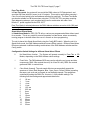
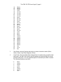
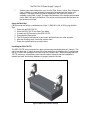
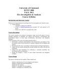
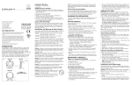
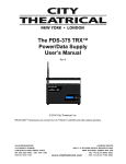
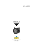
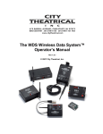
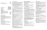
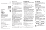
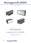
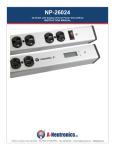
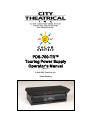
PDS-750-TR™
Touring Power Supply
Operator’s Manual
Rev 1.1
© 2004 City Theatrical, Inc.
Patent Pending
The PDS-750-TR Power Supply™ page 2
CONTENTS
The City Theatrical PDS-750-TR ...............................................................................................3
Cautions.....................................................................................................................................3
Compliance Certifications ..........................................................................................................3
Compatibility with Color Kinetics Equipment..............................................................................3
Color Kinetics Fixtures Supported ..........................................................................................3
Front Panel Controls ..................................................................................................................4
Back Panel Features..................................................................................................................5
Mains Power Requirements .......................................................................................................5
Connecting Color Kinetics fixtures to the PDS-750-TR..............................................................6
Operating Modes: CB, Pass Thru, or Stand-Alone ...................................................................6
CB Mode ................................................................................................................................6
Pass Thru Mode .....................................................................................................................7
Stand-Alone Effects Mode......................................................................................................7
Using the Mini-Zapi ..................................................................................................................10
Installing the PDS-750-TR .......................................................................................................10
Specifications ...........................................................................................................................11
FIGURES
Figure 1, PDS-750-TR, Front Panel...........................................................................................4
Figure 2, PDS-750-TR, Back Panel ...........................................................................................5
Figure 3 PDS-750-TR with C-Clamps ......................................................................................10
The PDS-750-TR Power Supply™ page 3
The City Theatrical PDS-750-TR
Thank you for using the City Theatrical PDS-750-TR™. Every effort has been made to
anticipate your questions in this manual, but if you have any questions that we don’t answer
here, or you want to discuss a special application, please feel free to contact use directly at
City Theatrical.
The CTI PDS-750-TR is a portable power supply unit provided with DMX 512 / Color
Kinetics® data management circuitry. It is designed to provide 24VDC power and standard
DMX512 distribution connections with DMX field addressing capability for Color Kinetics
Fixtures, including ColorBlast® 6, ColorBlast 12, and iColor Cove® (other CK fixtures are also
supported, check with your favorite lighting shop or City Theatrical for details).
Cautions
The PDS-750-TR is intended for use only by qualified professionals. Connection, installation
and hanging of this equipment must be performed in accordance with all pertinent local,
regional and national safety codes and regulations.
The PDS-750-TR is intended for indoor use only.
Keep the unit dry! Do not operate the unit if it gets wet!
Do not operate in excessive heat/direct sunlight.
Be sure installation provides adequate ventilation. Both the front and the back side of the unit
must be clear of obstruction and allow free airflow.
There are no user-serviceable parts inside! Refer to qualified service personnel!
Compliance Certifications
ETL Listed, Conforms to UL 508A
cETL Listed, Certified to Can/CSA Standard 22.2 14-95
Compatibility with Color Kinetics Equipment
The CTI PDS-750-TR is produced under license and with the cooperation and approval of
Color Kinetics Inc. and is the only such entertainment power supply and control system
approved for such use. City Theatrical, Inc. and Color Kinetics, Inc. have made every effort to
assure that the CTI PDS-750-TR is fully compatible and will operate reliably with Color
Kinetics CB and iColor Cove fixtures.
Color Kinetics Fixtures Supported
The PDS-750-TR will power and control the following Color Kinetics Fixtures:
• ColorBlast 12: 12 units, 1 per output
• ColorBlast 6: 24 units, 2 per output
• ColorBurst 6: 24 units, 2 per output
• ColorBurst 4: 48 units, 4 per output
• Colorsplash 2: 24 units, 2 per output
• iColor Cove: 96 units, 8 per output
The PDS-750-TR Power Supply™ page 4
PDS-750 TR
Figure 1, PDS-750-TR, Front Panel
Front Panel Controls
The PDS-750-TR front panel controls will generally look familiar to most professional users,
with a Pilot/Status Light, 3 BCD DMX Address Switch array, and a system reset switch. In
addition, the unit is provided with a Configuration BCD, overload indicators, and a Mini-Zapi™
Switch. All the control functions are described below:
1. Pilot / Status Light:
On = Power Present, System running
Blinking = No DMX
Solid = DMX Present
Green = CB Mode
Orange = Pass Thru Mode
Alternating Red/Green = Stand Alone Mode
2. Reset Switch: Press to reset the PDS-750-TR’s system microprocessor
3. DMX Address Switches: Left to right = 100’s, 10’s, 1’s
Set address to 000 for Pass Thru mode
Set address to any valid address 001 – 4761 for CB mode
4. Configuration Switch: Selects Stand-Alone Routines. Also may be used for special
functions
5. Channel Overload Indicator: Lights if internal circuit breaker is tripped, indicating an
overloaded output. If tripped, disconnect load and allow unit to cool (~ 2 minutes). Circuit
1
The unit may be addressed to start at any DMX value up to 512, however addresses above 476 will
waste outputs, as DMX values will not exist for all outputs.
The PDS-750-TR Power Supply™ page 5
breaker will re-set. Note: If internal circuit breaker trips, something is wrong.
Correct fault before using system!
6. Mini-Zapi™: Resets any connected Color Kinetics CB fixtures to Light 001 (DMX 001,002
& 003), preparing them for easy use with the CB Mode setting
Figure 2, PDS-750-TR, Back Panel
Back Panel Features
7. IEC Power Inlet, Connect Mains Power Cord here.
8. DMX INPUT, 5P XLR Male Panel Mount connector, auto-terminated
9. DMX OUTPUT, 5P XLR Female Panel Mount connector, a re-generated, optically isolated
DMX output (the Unit switches to passive hard-wired pass-thru if power is lost)
10. Fixture Output # 1, 4P XLR Female, for connection of Color Kinetics fixtures
11. Fan, do not obstruct
12. Fuse (10A 3AG)
Mains Power Requirements
The PDS-750-TR is is compatible with 100-240 VAC, 50/60 Hz Mains Power. The unit is
provided with a panel mount IEC Input connector for use with standard 100V – 240V cord
sets.
The PDS-750-TR Power Supply™ page 6
Connecting Color Kinetics fixtures to the PDS-750-TR
The PDS-750-TR is provided with Female 4 pin XLR connectors for output connection to the
CK fixtures. The connector pin out is as follows:
PIN #
Pin 1
Pin 2
Pin 3
Pin 4
Signal
+24VDC
(n/c)
Data
DC Common
CK Cable Wire Color
Red
White
Black
Color Kinetics CB fixtures are provided with a permanently connected 60ft/20m cable. As
60ft/20m is the maximum length specified by Color Kinetics, this length should not be
extended.
Color Kinetics manufactures an optional Data Amplifier/Repeater which may be inserted in the
run if additional length is needed. Please contact City Theatrical or Color Kinetics for
assistance and details.
Operating Modes: CB, Pass Thru, or Stand-Alone
The Unit can be configured for either DMX managed “CB” Mode, Pass Thru mode, or StandAlone Mode
CB Mode
In CB Mode, the system will route DMX (as CK Data protocol) to each output based on the
selected DMX starting address. Each fixture is set as CK Light 1 (DMX 001, 002, 003). The
PDS-750’s internal DMX Manager selectively routes DMX Data to each light output so that
each light receives only the data packets that it is supposed to respond to. The effective DMX
address of each fixture is a function of the starting address of the PDS-750, combined with the
number of the output that fixture is connected to.
With the DMX Address set to 001: Fixture 1 = DMX 1, 2 & 3, Fixture 2 = DMX 4, 5, & 6, etc.
To put the unit into CB Mode, simply set the DMX Address switches to a desired address
other than 000. The unit can be set to any valid DMX address, however please note that any
starting address over 476 will disable some outputs.
Configuration / system setup for CB (DMX managed) mode
1
2
3
4
5
Using the on-board Mini-Zapi (see, Using the Mini-Zapi page 10) or Color Kinetics Zapi™,
pre-address all CB fixtures as DMX 001.
Plug up to 12 of those CB fixtures into outputs 1 – 12
Connect the System to a DMX source via the DMX Input and connect power
Set the system’s DMX Address to the desired starting address value AAA
The 12 connected CB fixtures will respond as follows:
CB Fixture # 1 = DMX address AAA, AAA+1, AAA+2
CB Fixture # 2 = DMX address AAA+3, AAA+4, AAA+5
CB Fixture # 3 = DMX address AAA+6, AAA+7, AAA+8, etc.
The PDS-750-TR Power Supply™ page 7
Pass Thru Mode
In Pass Thru mode, the system will convert all the DMX values to CK Data protocol, and
send that CK Data (with 24V power) to all 12 outputs. This mode is useful when powering iColor Cove fixtures which have local address switches for each light. The Pass Thru Mode
can also be suitable for CB fixtures when using the CTI PDS-750-TR in a system requiring
Zapi addressing schemes, such as when being used in combination with other Color
Kinetics™ power supplies like the PDS-150™
Pass Thru Mode is selected whenever the DMX Address switches are set to all 0s (000) and
the Config Switch is set to 0
Stand-Alone Effects Mode
In Stand-Alone Mode the PDS-750-TR will run various pre-programmed effects without need
for a console. This is very useful for events like parties or trade shows, where a constantly
running program is desired without the use of a console or show programming.
The unit is placed into Stand-Alone Mode using the Config BCD switch. When the unit is in
Stand-Alone mode, the DMX Address switches become Effect controls. Different Stand-Alone
Effects are selected via different setting combinations of the DMX Address switches and the
Config switch
Configuration Switch Settings for different Stand-Alone Effects
0
No Stand-Alone function. The System will operate normally in Pass-Thru or CB
Modes, depending on the DMX Address switch settings.
1
Fixed Color. The DMX address BCDs are used to adjust the red, green and blue
components. DMX 100s controls the red (0 is off and 9 is full), DMX 10s controls
green and DMX 1s controls blue.
2
Color Wash (forward). The color wash effect moves sequentially around the
spectrum of colors (Red, Magenta, Blue, Cyan, Green, Yellow & White) repeating
the same cycle over and over again at user definable speeds. The speeds are
controlled by setting the DMX 10s & ones to 1 of 48 possible settings. The
following lists their settings and approximate fade times.
0
1
2
3
4
5
6
7
8
9
10
11
12
13
.25 sec
.3 sec
.4 sec
.6 sec
1.25 sec
2.55 sec
4 sec
5 sec
10 sec
15 sec
20 sec
25 sec
30 sec
35 sec
The PDS-750-TR Power Supply™ page 8
14
15
16
17
18
19
20
21
22
23
24
25
26
27
28
29
30
31
32
33
34
35
36
37
38
39
40
41
42
43
44
45
46
40 sec
45 sec
50 sec
1 min
1.2 min
1.3 min
1.5 min
1.6 min
2 min
2.3 min
2.6 min
3 min
3.5 min
4 min
4.5 min
5 min
5.5 min
6 min
6.5 min
7 min
8 min
9 min
10 min
12 min
15 min
20 min
25 min
30 min
40 min
50 min
1 hr
1.5 hr
2 hr
3
Color Wash (reverse).Same as above but in counter clockwise rotation (White,
Yellow, Green, Cyan, Blue, Magenta, & Red).
4
Cross-Fade. The Cross-Fade effect changes from one preset color to another than
back again. The DMX 100s switch sets the starting color and the DMX 10s switch
sets the ending color. The user specified speed is controlled by the DMX 1s switch.
The following speeds are provided.
0
1
2
3
4
5
6
7
5 sec
10 sec
30 sec
1 min
2 min
15 min
30 min
1 hr
The PDS-750-TR Power Supply™ page 9
5
The random color effect produces random colors at user definable speeds. The
randomly generated color steps from one to the next without and fading. Speed is
controlled by the DMX 10s and 1s digits. The following speeds are provided:
0
1
2
3
4
5
6
7
8
9
10
11
12
13
14
15
16
17
18
19
20
21
22
23
24
25
26
27
28
29
6
.075 sec
.1 sec
.15 sec
.2 sec
.275 sec
.325 sec
.375 sec
.5 sec
.625 sec
.95 sec
1.25 sec
1.5 sec
1.875 sec
2.5 sec
3.125 sec
4.375 sec
5.625 sec
6.25 sec
9.375 sec
12.5 sec
15 sec
18.75 sec
31.25 sec
37.5 sec
56.25 sec
1.25 min
1.875 min
2.5 min
3.125 min
3.75 min
Fixed color strobe uses the DMX 100s switch to choose the color (1-Red, 2-Green,
3-Yellow, 4-Blue, 5-Magenta, 6-Cyan, 7-White, 8&9-Black). The strobe rate is
controlled by the DMX 1s digit. The following rates are provided:
0
1
2
3
4
5
6
7
20/sec
13/sec
10/sec
7.5/sec
5/sec
4/sec
3/sec
2/sec
The PDS-750-TR Power Supply™ page 10
7
Variable color strobe steps from color to color (Red, Green, Yellow, Blue, Magenta,
Cyan, & White) in a user definable time period at a strobe rate that is also user
definable. The same strobe rate that is employed in the fixed color strobe is
available via the DMX 1s digit. The step times between color changes are provided
via the DMX 100s and 10s switches. The values and time periods are the same as
the random color effect.
Using the Mini-Zapi
CB fixtures can be quickly re-addressed as “Light 1” (DMX 001, 002, & 003) using the MiniZapi.
1. Power Up the PDS-750-TR
2. Place the PDS-750-TR into Pass-Thru Mode
3. Connect the CB Fixture(s) to the PDS-750-TR.
4. Press the Mini-Zapi button.
5. The CB fixture(s) will light red for a moment and then flicker for a few seconds.
6. After the flickering stops, Power the system down.
7. Power the system back up to test the units.
Installing the PDS-750-TR
The PDS-750-TR can be mounted to a pipe or truss using standard theatrical C-clamps. The
Unit is provided with ½” holes on each side of the case cover for attaching the C-clamps, and
with a ⅛” hole in the left edge of the case cover for a safety cable. When mounting the PDS750-TR in this way, all necessary care should be taken to assure that the installation is
suitable and safe, and that the hardware is properly rated for the task.
Figure 3 PDS-750-TR with C-Clamps
The PDS-750-TR Power Supply™ page 11
Specifications
Dimensions: 18.50” x 5.218” x 8.50”
Weight: 13.5 Lbs.
Electrical Specifications:
• Input Power 100-240VAC 50/60 Hz 600 Watts
• Output Power 24VDC 20Amps Max
Features:
• Heavy Duty NEMA 1 Steel and Aluminum enclosure
• 100-240 VAC 50/60hz Mains Power (auto-ranging)
• Mounting points for C-Clamps & Safety Cable
• (12) 4P XLRF CK Data/24V Power output connectors for fixture connection
• DMX 512 Interface (see below)
• 1 x 750 Watt internal power supply
• 24VDC 3A current limited per circuit output with LED Fault Indication
• One-touch Mini-Zapi feature for reconfiguring fixtures with correct starting DMX
Address
• Includes 7 types of user-configurable fade and chase routines for stand-alone
operation
• In Stand-Alone Mode, selected routine is output to DMX Pass-Thru for synchronized
Stand-Alone operation of many CB Supply systems
DMX 512 Interface:
• DMX Input via 5P XLR Male
• Isolated and repeated DMX Pass-Thru via 5P XLR Female
• DMX Address interface utilizing 3 Rotary BCD Switches for DMX Address
configuration
CK Output Configuration
•
•
•
12 outputs providing Color Kinetics control protocol, +24VDC, and Ground
“CB Mode”: DMX converted to CK protocol and output selectively to each port as per
BCD address setting (see below)
“iCove Mode”: All 512 DMX values converted to CK Protocol and output on all ports
Options:
•
•
Rack mount
Pipe Mount
•
•
Terminal Block Output
ETL/cETL Version
•
•
4P XLR Output
CE Version
*Fixtures Supported: ColorBlast 12, ColorBlast 6, ColorBurst 6®, ColorBurst 4®, iColor Cove®