1
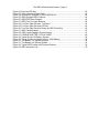
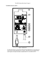
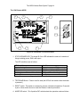
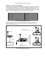
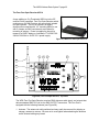
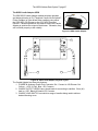
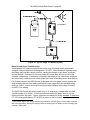
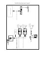
The WDS Wireless Data System™
Operator’s Manual
Rev 1.9.1
© 2007 City Theatrical, Inc.
The WDS Wireless Data System™ page 2
CONTENTS
Welcome to the WDS Wireless Data System ............................................................................5
Getting Started with the WDS Wireless Data System................................................................5
The WDS Transmitter # 5500 (200MW) or #5501 (10MW)........................................................7
The WDS Receiver #5510 .........................................................................................................9
The WDS Rx2 Receiver #5512 ................................................................................................11
The 15A Dimmer #5520 ...........................................................................................................14
The WDS Personal Dimmer #5515..........................................................................................17
Personal Dimmer Radio Controls .........................................................................................18
Personal Dimmer Operating and Protective Features..........................................................19
Switch Diagnostics ...............................................................................................................20
The OEM Receiver #5505 .......................................................................................................21
Operating the WDS OEM Receiver (Rx) ..............................................................................22
Standard Accessories ..........................................................................................................23
Applications in City Theatrical’s PDS Range ...........................................................................24
The Four Port Opto-Receiver #5514........................................................................................25
The WDS Candle Adapter #5580 ............................................................................................27
User Application Notes: ........................................................................................................28
Batteries and Power Considerations ....................................................................................29
Working in the Wireless World .................................................................................................33
Range...................................................................................................................................33
Interference ..........................................................................................................................33
Accessories ..........................................................................................................................33
General Specifications .............................................................................................................34
Unit Specifications ...................................................................................................................34
FIGURES
Figure 1, Typical WDS System Riser.........................................................................................5
Figure 2, WDS Transmitter Front and Back Panels ...................................................................7
Figure 3, Transmitter LED Key ..................................................................................................8
Figure 4, WDS Receiver Top and Back Panels .........................................................................9
Figure 5, Receiver LED Key ....................................................................................................10
Figure 6, Radio Selection Chart ...............................................................................................10
Figure 7, Rx2 Receiver ............................................................................................................11
Figure 8, Rx2 LED Key ............................................................................................................12
Figure 9, Radio Selection Chart ...............................................................................................12
Figure 10, 15A Dimmer Top and Front Panel ..........................................................................14
Figure 11, 15A Dimmer LED Key.............................................................................................14
Figure 12, Mode Switch Selection Chart..................................................................................15
Figure 13, Switch Diagnostics..................................................................................................16
Figure 14, WDS Personal Dimmer...........................................................................................17
Figure 15, Radio & Dip Switch Key ..........................................................................................18
Figure 16, PD Radio LED Key .................................................................................................18
Figure 17, PD Dimmer LED Key ..............................................................................................18
Figure 18, PD Mode Dip Switch Key........................................................................................19
Figure 19, XLR Tail Pin Configuration .....................................................................................19
Figure 20, PD Switch Diagnostics............................................................................................20
Figure 21, WDS OEM Receiver Card Layout...........................................................................21
The WDS Wireless Data System™ page 3
Figure 22, Receiver LED Key ..................................................................................................22
Figure 23, Radio Selection Switch Chart .................................................................................22
Figure 24, Accessories Available for WDS OEM Rx Kit...........................................................23
Figure 25, WDS Equipped PDS Products................................................................................24
Figure 26, WDS/PDS Riser Example.......................................................................................24
Figure 27, WDS Four Port Opto-Reciever ...............................................................................25
Figure 28, Four Port Opto-Receiver, Top Panel ......................................................................25
Figure 29, Four Port Opto-Receiver LED Key..........................................................................26
Figure 30, Four Port Opto-Receiver Rotary and DIP Switch Key ............................................26
Figure 31, WDS Candle Adapter .............................................................................................27
Figure 32, 5580 Candle Adapter, Physical Layout...................................................................27
Figure 33, CANDLE ADAPTER TYPICAL RISER ...................................................................28
Figure 34, Typical Single 12V Battery System.........................................................................29
Figure 35, Typical Continuous Battery Life for 12AH Battery...................................................30
Figure 36, Two Battery 12V (parallel) System .........................................................................30
Figure 37, Two Battery 24V (series) System ...........................................................................31
Figure 38, Typical WDS System with Personal Dimmer ..........................................................32
Figure 39, WDS Accessory List ...............................................................................................33
The WDS Wireless Data System™ page 4
** Does not Include France or Spain
Other Countries:
Some countries not listed accept emissions / broadcast radio compliance certifications from
the countries listed above. Other national compliance certification applications are pending
and may be secured in the future. For current information about a country not listed above,
please contact City Theatrical.
The WDS Wireless Data System™ page 5
Welcome to the WDS Wireless Data System
Thank you for choosing the WDS Wireless Data System™. The WDS System has been
engineered to be reliable, roadworthy, easy to use, and compatible with other standard
2.4GHz wireless data and communications systems. Every effort has been made to
anticipate your questions in this manual, but if you have any questions that are not answered
here, or you want to discuss a special application, please feel free to contact us directly at City
Theatrical. The WDS System includes a wide range of products which you may review at our
website (www.citytheatrical.com) or in our catalog. For basic operation, a minimum of one
WDS Transmitter and one WDS Receiver is required.
Getting Started with the WDS Wireless Data System
Setting up a WDS system is quite similar to setting up any DMX512 based system. The
principle thing to remember is that the WDS Transmitter and Receiver(s) replace DMX cable.
System Flow: DMX 512 control data from any standard DMX 512 console is output to the
WDS Transmitter, which converts that DMX data to a radio signal and broadcasts it to the
WDS Receiver (or Receivers). The WDS Receiver takes the radio broadcast and converts it
back into standard DMX 512 data, which can than be connected via standard cables to WDS
15A Dimmers or any other DMX devices such as moving lights, effects, etc.
LOAD
TRANSMITTER
12 ~ 24V
BATTERY
0
15A DIMMER
DMX 512 CONTROL CABLE
FROM CONSOLE TO TRANSMITTER
LIGHTING CONSOLE
RECEIVER
Figure 1, Typical WDS System Riser
The WDS Wireless Data System™ page 6
Connection and configuration of a typical WDS System:
1. Install the WDS Transmitter in a convenient location within range1 of the desired
Receiver location(s). Transmitters should be elevated above the audience (or other
barriers) whenever possible; height is good!
2. Set the WDS Transmitter’s radio channel via the Radio Channel rotary switch (1
through 8) and System ID 2 position DIP switch (see Figure 2 for details.) The
Transmitter and Receiver radio channel and system ID settings must match for
them to communicate.
3. Connect the DMX 512 Console’s DMX output to the WDS Transmitter via a standard
DMX 512 cable and then connect the transmitter power supply. After the unit is
powered up and initializes itself, the status LEDs will read:
a. POWER/DMX IN: Amber
b. RF OUT: Amber
4. Set the WDS Receiver’s radio channel to match the Transmitter via its channel rotary
switch and system ID two position DIP switch.
5. Connect Receiver power using either a WDS DC power adapter (#5525 or #5527) or a
WDS Battery Cable (#5550, #5552, #5554, or #5556). After power up and initialization,
the Receiver status LEDs will read:
a. POWER/IN RANGE: Amber
b. RF IN/DMX OUT: Amber
6. Set the Dimmer’s DMX address to any desired value between 1 and 512 using the
DMX address switches.
7. Connect the Dimmer to (battery) power via the POWER IN connectors, and connect
the load via the DIMMER OUT connectors. After power up and initialization, the
Dimmer POWER/STATUS LED should be blinking green.
8. Connect the Receiver’s DMX output to the DMX input of the WDS Dimmer. The
Dimmer POWER/STATUS LED should now be solid green.
9. Test the load connection using the TEST/bump button.
10. When the Dimmer is brought up to a level, the POWER/STATUS LED will track the
level dimming between Green at OFF and Amber at FULL.
About the LEDs: All of the WDS Status LEDs are bi-color, meaning they each contain a red
and a green LED element. When both elements are fired, the LED will appear amber.
1
(see Working in the Wireless World, page 33)
The WDS Wireless Data System™ page 7
The WDS Transmitter # 5500 (200MW) or #5501 (10MW)
0
FRONT VIEW
REAR VIEW
Figure 2, WDS Transmitter Front and Back Panels
The WDS Transmitter receives standard DMX 512 via its DMX INPUT, and broadcasts that
DMX data as a radio signal. The Transmitter is equipped with the following features (see
Figure 2):
Front Panel:
1. Antenna: The antenna is multi-positional and may easily be removed for shipping or
storage; unscrew to remove. Be sure not to over-tighten when attaching the antenna
as the internal cabling may break.
2. RF OUT LED (item 2): This LED indicates inter-processor communication and RF
broadcast. During normal operation, the LED will flash green briefly to indicate the
internal processors are communicating. Once valid DMX is established, this LED will
go to steady amber to indicate that the Transmitter is broadcasting.
3. Power/DMX IN LED (item 3): This LED will light green to indicate power is connected,
and change to red/amber when ever DMX input is detected. It flashes between green
and amber if DMX is lost after being detected.
The WDS Wireless Data System™ page 8
LED Indicator
Color/Status
Momentary Flash Green/Red
Indication
CPUs Communicating,
System Ready
RF OUT LED (item 2)
Steady Amber
Transmitting
Steady Amber
DMX Data Present
Power/DMX IN LED (item 3)
Flashing between Green and Amber
Power ON, No DMX
Figure 3, Transmitter LED Key
4. RADIO ID CHANNEL select switch: Switch positions 1-8 select (settings 9 & 0 are
reserved for diagnostics and special functions.)
5. ID DIP switch: This 2 position DIP switch works with the Radio Channel select switch
to permit selection of any of the 32 available radio channels, as per the chart below.
Note: On the Transmitter, these switches are OFF when they are UP.
Radio Channel Select Switch ID DIP Switch Radio Channels
1-8
OFF OFF
1–8
1-8
ON OFF
9 – 16
1-8
OFF ON
17 – 24
1-8
ON ON
25 – 32
6. RESET switch: This switch is recessed to prevent unintentional operation. Press with
a pen or other similar device to reset the Transmitter’s internal processors.
Back Panel:
7. DMX INPUT, 5P XLR Male: This is a standard DMX 512 input. Connect to the
desired output port of your console to broadcast that port’s DMX 512 data.
8. DMX PASS-THRU, 5P XLR Female: This Pass-Thru is provided to allow connection
of down-stream DMX devices. The WDS Transmitter DMX output is optically isolated
from the input, CPU set, and other Transmitter circuitry.
DMX INPUT/PASS-THRU special features:
• The DMX INPUT is provided with auto-termination, so no other end-of-line
termination setting is required.
• During normal operation, the WDS Transmitter regenerates the DMX 512 DATA
presented at the Pass-Thru output, so the output may supply a full compliment of
DMX load.
• If the power supply is removed or other system failure occurs, the DMX input will
automatically be switched over to a hardwired connection to the pass-thru,
assuring continued delivery of the DMX data to down stream devices.
9. +12V power supply connection: Connect the Mains Power/+12V adapter here to
power the unit.
CE Compliance:
The #5501 (10MW) Transmitter is available in a CE compliant version.
The WDS Wireless Data System™ page 9
The WDS Receiver #5510
6
8
7
4
5
3
2
1
Figure 4, WDS Receiver Top and Back Panels
The WDS Receiver receives DMX data as a radio signal, and outputs that data as standard
DMX 512 via its DMX OUTPUT connector. The Receiver is equipped with the following
features (see Figure 2):
1. Antenna: The antenna is multi-positional and may easily be removed for shipping or
storage; unscrew to remove. Be sure not to over-tighten when attaching the antenna
as the internal cabling may break
2. POWER/IN RANGE LED (D4): This LED indicates the unit has Power and is in range
of a Transmitter. This LED will light Green to indicate power is connected, and change
to Amber whenever a correctly configured Transmitter is detected.
The WDS Wireless Data System™ page 10
3. RF IN/DMX OUT LED (D3): This LED lights Green when the unit is receiving RF DMX
data and Red when outputting standard DMX. Since the unit begins outputting DMX as
soon as it receives RF, this LED normally appears amber when receiving/outputting.
LED Indicator
POWER/IN RANGE (2)
RF IN/DMX OUT (3)
Color/Status
Green
Amber
Green
Amber
Indication
Power Connected
Transmitter Detected
Receiving RF DMX
Outputting DMX
Figure 5, Receiver LED Key
4. RADIO CHANNEL select switch: Switch positions 1-8 select (settings 9 & 0 are
reserved for diagnostics and special functions).
5. ID DIP switch: This 2 position DIP switch works with the Radio Channel select switch
to permit selection of any of the 32 available radio channels, as per the following chart:
Radio Channel Select Switch
1-8
1-8
1-8
1-8
ID DIP Switch
OFF OFF
ON OFF
OFF ON
ON ON
Radio Channels
1-8
9 - 16
17 - 24
25 - 32
Figure 6, Radio Selection Chart
6. RESET switch: This switch is recessed to prevent unintentional operation. Press with
a pen or other similar device to reset the Receiver’s internal processors.
7. DMX OUTPUT, 5P XLR Female: This is a standard DMX 512 output. Connect to
WDS Dimmers or other DMX devices.
8. +12V power supply connection. Connect the Mains Power/+12V adapter or +12V
battery here to power the unit.
CE Compliance
The #5510 Receiver is available in a CE compliant version.
The WDS Wireless Data System™ page 11
The WDS Rx2 Receiver #5512
9
7
3
2
4
5
6
1
8
Figure 7, Rx2 Receiver
The WDS Rx2 Receiver is a full-featured WDS Wireless DMX Receiver for use wherever a
mains powered wireless DMX Receiver is needed. The WDS Rx2 receives DMX data as
a radio signal, and outputs that data as standard DMX 512 via its DMX OUTPUT
The WDS Wireless Data System™ page 12
connector. The Rx2 is ETL Listed to UL 508A and is available in a CE compliant version.
The socket-outlet shall be installed near the equipment and shall be easily accessible, i.e.,
do not run excessively long extensions cords of insufficient gauge to power the unit.
The Rx2 is equipped with the following features:
1. Antenna: The antenna is multi-positional and may easily be removed for shipping or
storage; unscrew to remove. Be sure not to over-tighten when attaching the antenna
as the internal cabling may break.
2. POWER LED (L1): This LED indicates the unit has power and is in range of a
Transmitter. This LED will light red to indicate power is connected, and change to
amber whenever a correctly configured Transmitter is detected.
3. RF LED (L2): This LED lights Red when the unit is receiving RF DMX data and green
when outputting standard DMX. Since the unit begins outputting DMX as soon as it
receives RF, this LED normally appears amber when receiving/outputting.
L1
L2
Status
Red
Power ON, No Tx Detected
Amber Amber Tx Detected, DMX Transmitting
Red
Red
Tx Detected, DMX Lost
Figure 8, Rx2 LED Key
4. RADIO CHANNEL select switch: Switch positions 1-8 select (settings 9 & 0 are
reserved for diagnostics and special functions).
5. ID DIP switch: This 2 position DIP switch works with the Radio Channel select switch
to permit selection of any of the 32 available radio channels, as per the chart below.
Note ON/OFF markings on the DIP switches.
Radio Channel Select Switch ID DIP Switch Radio Channels
1-8
OFF OFF
1-8
1-8
ON OFF
9 - 16
1-8
OFF ON
17 - 24
1-8
ON ON
25 - 32
Figure 9, Radio Selection Chart
6. RESET switch: This switch is recessed to prevent unintentional operation. Press with
a pen or other similar device to reset the Rx2’s internal processors.
7. DMX OUTPUT, 5P XLR Female: This is a standard DMX 512 output. Connect to
WDS Dimmers or other DMX devices
8. Auto-ranging Mains Power Connection: Connect to 100~240 VAC 50/60 Hz. Although
provided with a standard North American NEMA 5-15P (“Edison”) power plug, the Rx2
will work with any mains power voltage within the 100~240 VAC 50/60 Hz range.
9. C-Clamp Attachment: The Rx2 can be fitted with a standard theatrical C-Clamp for
pipe and truss mounting.
The WDS Wireless Data System™ page 13
Fuse Replacement
In the event that your Rx2’s fuse has blown, it can be replaced by a qualified individual.
Remove the (4) flat head Philips screws securing the cover, locate the fuse on the power
supply circuit board and carefully remove. Replace with a .25A 250V 2AG/5mm fuse,
carefully snapping it into place. Replace the cover and screws, and test the unit to make sure
it is working properly.
The WDS Wireless Data System™ page 14
The 15A Dimmer #5520
TOP VIEW
5
FRONT VIEW
3
4
1
8
9
6
7
2
Figure 10, 15A Dimmer Top and Front Panel
1. STATUS/POWER LED: This single Bi-Color LED indicates the status of a number of
things including power, DMX, and output.
The LED conditions are as follows:
LED State/Color
Regular blinking Green
Solid Green
Solid Amber
Flashing between Red and Green/Amber
Flashing Red
Condition
Dimmer has power, CPU is running
DMX Present, Output OFF
DMX Present, Output FULL
DMX Lost, Dimmer holding Last Level
Low Battery
Figure 11, 15A Dimmer LED Key
2. TEST/BUMP Button: Press to test fire load (the LED will turn amber when the button
is pressed.)
3. RESET switch: This switch is recessed to prevent unintentional operation. Press with
a pen or other similar device to reset the Dimmer’s internal processors.
4. MODE DIP switch: This 2 position DIP switch selects the operation mode as follows
The WDS Wireless Data System™ page 15
Switch Setting
OFF OFF
ON OFF
OFF ON
ON ON
Function
Normal Dimming, ISL Curve
NON - DIM
Linear Dimming Curve
Reserved
Figure 12, Mode Switch Selection Chart
5. DMX ADDRESS BCD Rotary Switches: These BCD rotary switches are used to set
the unit’s specific DMX address to any value from 1 to 512.
6. POWER IN Anderson Power Pole Connector Set: Connect to Battery Power. Red =
+12-24VDC, Black = DC Common.
7. DIMMER OUT Anderson Power Pole Connector Set: Connect to the load to be
dimmed. Yellow = + VDC (0-Full), Blue = DC Common .
8. DMX INPUT, 5P XLR Male: This is a standard DMX 512 input. Connect to the DMX
output port of the Receiver, or any standard DMX output device.
9. DMX PASS-THRU, 5P XLR Female: This pass-thru is provided to allow connection of
downstream DMX devices.
DMX INPUT/PASS-THRU special features:
• The DMX INPUT is provided with auto-termination, so no other end-of-line
termination setting is required.
• During normal operation, the WDS 15 Amp Dimmer re-generates the DMX 512
data presented at the Pass-Thru output, so the output may supply a full
compliment of DMX load.
• If the power supply is removed or other system failure occurs, the DMX input
will automatically be switched over to a hardwired connection to the pass-thru,
assuring continued delivery of the DMX data to downstream devices.
Protective Features
• Low Battery Power: If the connected Battery drops below a preset voltage, the
Dimmer will shut down, and will not restart until reset (the Low Battery indication will
light). This feature protects rechargeable batteries from discharging to the point where
they cannot be recharged with a standard charger. The standard factory set cut-off
point is 7VDC. Other settings are available on a custom basis; please consult City
Theatrical.
•
Internal Watchdog for DMX processor and Dimmer Processor: If the DMX processor
fails, the LED will flash at 1 sec interval (red or amber depending on DMX failure
mode) and the load output will be turned off, protecting the battery and load. If the
Dimmer processor fails, the load output will be turned off, protecting the battery and
load.
•
Internal reverse power polarity protection: The internal power supply circuitry is
designed to protect the control electronics from damage if the battery leads are
accidentally reversed or plugged into the DIMMER OUTPUT connection.
The WDS Wireless Data System™ page 16
•
Hold Last valid DMX Level: If DMX is lost, the WDS 15A Dimmer will hold the last
valid level for about 5 minutes, and then fade to black.
Switch Diagnostics
Setting the BCDs to the settings shown below and resetting the unit will start the following
diagnostic self tests:
BCD
Settings
MODE DIP
Settings
Function
Tested
601
Ones (1s) BCD
602
Tens (10s) BCD
603
Hundreds
(100s) BCD
604
605
00
01
10
11
DIP Switch
DIP Switch
DIP Switch
DIP Switch
Manually Set
Output Level
Indication
LED Will flash
= to the number
the “1s” BCD is set to
LED Will flash
= to the number
the “10s” BCD is set to
LED Will flash
= to the number
the “100s” BCD is set to
No LED Flashes
1 LED Flash
2 LED Flashes
Fast Red/Green/Amber Flashes
After reset move the tens and ones BCD
switches to manually set the lamp to a % level
Figure 13, Switch Diagnostics
The BCD test setting must be set (as above) ether before power is applied or reset is
pressed.
Fuse Replacement
The 15A Dimmer contains a replaceable ATO 15A Fuse. Refer to qualified service personnel
if your unit needs a fuse replacement.
Wire Gauge
When installing this unit in a system, City Theatrical recommends 12 gauge wiring between all
line and load devices to minimize voltage drop, otherwise significant damage could result to
the equipment.
Operating Temperature
Maximum ambient operating temperature is 40°C.
CE Compliance
The #5520 15A Dimmer is available in a CE compliant version. Look for the CE marking to
verify.
The WDS Wireless Data System™ page 17
The WDS Personal Dimmer #5515
The WDS Personal Dimmer combines a WDS DC Dimmer with its own dedicated 2.4GHz
Receiver to provide wireless dimming in a very small, lightweight and concealable package
that can be worn with the provided belt clip, or hidden in a prop or set piece. The Personal
Dimmer is internally fused at 5A.
Features:
• Integral 32 Channel 2.4GHz WDS Receiver
• Integral Class 2 power limited 5A Dimmer
• Operating power range +9~24 VDC
• Very small size
• Use with belt clip or mount flat in prop or set piece
• Works with Standard WDS Transmitter
• Can be used in any WDS system with all other WDS products
1
2
3
4
5
6
7
8
9
10
11
Figure 14, WDS Personal Dimmer
The WDS Wireless Data System™ page 18
Personal Dimmer Radio Controls
1. POWER/IN RANGE LED (D4): This LED indicates the unit has power and is in range
of a Transmitter. This LED will light green to indicate power is connected, and change
to amber whenever a correctly configured Transmitter is detected.
2. ID DIP switch: This 2 position DIP switch works with the radio channel select switch to
permit selection of any of the 32 available radio channels, as per the following chart:
Radio Channel Select Switch ID DIP Switch Radio Channels
1-8
OFF OFF
1-8
1-8
ON OFF
9 - 16
1-8
OFF ON
17 - 24
1-8
ON ON
25 - 32
Figure 15, Radio & Dip Switch Key
3. RADIO CHANNEL select switch: Switch positions 1-8 select (settings 9 & 0 are
reserved for diagnostics and special functions).
4. RF IN/DMX OUT LED (D3): This LED lights green when the unit is receiving RF DMX
data and red when outputting standard DMX. Since the unit begins outputting DMX as
soon as it receives RF, this LED normally appears amber when receiving/outputting.
Radio LED Indicator Color/Status
Indication
Green
Power Connected
POWER/IN RANGE
Amber
Transmitter Detected
Green
Receiving RF DMX
RF IN/DMX OUT
Amber
Outputting DMX
Figure 16, PD Radio LED Key
5. RESET switch: This switch will reset the entire Personal Dimmer unit (both Radio
receiver and Dimmer). It is recessed to prevent unintentional operation. Press with a
pen or other similar device to reset the Personal Dimmer’s internal processors.
6. STATUS/POWER LED: This single Bi-Color LED indicates the status of a number of
things including power, DMX, and output.
The LED conditions are as follows:
Dimmer LED State/Color
Condition
Regular blinking Green
Dimmer has power, CPU is running
Solid Green
DMX Present, Output OFF
Solid Amber
DMX Present, Output FULL
Flashing between Red and Green/Amber DMX Lost, Dimmer holding Last Level
Flashing Red
Low Battery
Figure 17, PD Dimmer LED Key
The WDS Wireless Data System™ page 19
7. DMX ADDRESS BCD Rotary Switches: These BCD rotary switches are used to set
the unit’s specific DMX address to any value from 1 to 512.
8. TEST/BUMP Button: Press to test fire load (the LED will turn amber when the button
is pressed).
9. MODE DIP switch: This 2 position DIP switch selects the operation mode as follows:
Switch Setting
Function
OFF OFF
Normal Dimming, ISL Curve
ON OFF
NON - DIM
OFF ON
Linear Dimming Curve
ON ON
Reserved
Figure 18, PD Mode Dip Switch Key
10. 4P XLR Tail for power input and load output connections:
Pin
Function
1
Input DC Common
2
Input 9~12 +VDC
3
Output DC Common
4 Output Dimmed +VDC
Figure 19, XLR Tail Pin Configuration
11. Flexible antenna
Personal Dimmer Operating and Protective Features
•
Class 2 Power Limitation: Because the Personal Dimmer is intended for use in
installations where actors, dancers and technicians may come into regular contact with
the unit while it is operating, it is pre-configured as an NEC 725 Class 2 low power
device with a 12V 5A / 60W maximum power limitation. If control is needed for higher
voltage or higher wattage devices, the standard 15A Dimmer or 30A Custom Dimmer
should be used.
•
9V Battery operation: The WDS Personal Dimmer will operate with small loads from a
single 9V Battery. In a typical application, the Personal Dimmer with a .150A load will
run for up to two hours on a single 9V Battery. Two or more batteries may be
connected in parallel for extended operation or higher loads.
•
Low Battery Power Sense: If the connected Battery drops below a preset voltage, the
Dimmer will shut down, and will not restart until reset (the Low Battery indication will
light). This feature protects rechargeable batteries from discharging to the point where
they cannot be recharged with a standard charger. The standard factory set cut-off
point for the Personal Dimmer is 5.5VDC. Other settings are available on a custom
basis, please consult City Theatrical.
The WDS Wireless Data System™ page 20
•
Internal Watchdog for DMX processor and Dimmer Processor: If the DMX processor
fails, the LED will flash at 1 sec interval (red or amber depending on DMX failure
mode) and the load output will be turned off, protecting the battery and load. If the
Dimmer processor fails, the load output will be turned off, protecting the battery and
load.
•
Internal reverse power polarity protection: The internal power supply circuitry is
designed to protect the control electronics from damage if the battery leads are
accidentally reversed or plugged into the DIMMER OUTPUT connection.
•
Hold Last valid DMX Level: If DMX is lost, the WDS PD will hold the last valid level for
about 5 minutes, and then fade to black.
Switch Diagnostics
Setting the BCDs to the settings shown below and resetting the unit will start the following
diagnostic self tests:
BCD
Settings
MODE DIP
Settings
Function
Tested
601
Ones (1s) BCD
602
Tens (10s) BCD
603
Hundreds
(100s) BCD
604
605
00
01
10
11
DIP Switch
DIP Switch
DIP Switch
DIP Switch
Manually Set
Output Level
Indication
LED Will flash
= to the number
the “1s” BCD is set to
LED Will flash
= to the number
the “10s” BCD is set to
LED Will flash
= to the number
the “100s” BCD is set to
No LED Flashes
1 LED Flash
2 LED Flashes
Fast Red/Green/Amber Flashes
After reset move the tens and ones BCD
switches to manually set the lamp to a % level
Figure 20, PD Switch Diagnostics
The BCD test setting must be set (as above) either before power is applied or reset is
pressed.
The WDS Wireless Data System™ page 21
The OEM Receiver #5505
The 5505 WDS OEM Wireless DMX 512 Receiver can be built into any DMX device, providing
instant cable-free connectivity with the mission critical reliability of 2.4GHz Frequency Hopping
Spread Spectrum (FHSS) technology. For installation instructions, please refer to “The WDS
OEM™ Wireless DMX Receiver Installation and User’s Guide.”
The WDS OEM Wireless Receiver includes the following features:
• Works with standard WDS Transmitter
• Miniature size (1.95” x 2.65”) PCBA
• Advanced surface mount technology
• 4 layer FR4 UL94-V0 PC Board
• Status LEDs for radio functions, power and DMX output
• DMX512 Output via 5 pin .100” Header
• Reception capability: 512 channels of DMX 512 data (1 full universe)
• 32 user selectable FHSS hopping patterns
• Typical effective range:
o 400 ~ 600’ indoors with standard antennas (line of sight)
o 1000’ ~ 1500’ outdoors with standard antennas (line of sight)
o 800 yards ~ several miles, with high power directional antennas, depending on
transmitter power, antennas and broadcast environment
• Compliance:
o CE Certified, RoHS Compliant
o 10 mW Transceiver - US (FCC15.247), Canada (IC), Europe (EN, Does not
include France or Spain)
OEM RADIO TRANSCEIVER
RADIO ID BCD SWITCH
RESET SWITCH
RADIO ID DIP SWITCH
L2 LED
L1 LED
OEM Rx PCBA
4-40 NYLON TRANSCEIVER MOUNTING HARDWARE
OEM Rx ASSEMBLY MOUNTING HOLE
Figure 21, WDS OEM Receiver Card Layout
The WDS Wireless Data System™ page 22
Operating the WDS OEM Receiver (Rx)
The WDS OEM Rx receives DMX data as a radio signal, and outputs that data as
standard DMX 512 via its DMX OUTPUT connector, just like other WDS products. The
only difference is the WDS OEM Rx can be installed in any number of devices not
manufactured directly by City Theatrical.
The OEM Rx is equipped with the following features:
1. Antenna: The OEM Rx will work with a number of antennas. City Theatrical stocks a
small flexible “Rubber Ducky” with integral cable and a (longer range) 7” adjustable/
removable unit that uses a separate cable. Kits will be equipped based on your
specific application and order.
2. POWER LED (L1): This LED indicates the unit has power and is in range of a
Transmitter. This LED will light red to indicate power is connected, and change to
Amber whenever a correctly configured Transmitter is detected.
3. RF LED (L2): This LED lights red when the unit is receiving RF DMX data and green
when outputting standard DMX. Since the unit begins outputting DMX as soon as it
receives RF, this LED normally appears amber when receiving/outputting.
L1
L2
Status
Red
Power ON, No Tx Detected
Amber Amber Tx Detected, DMX Transmitting
Red
Red
Tx Detected, DMX Lost
Figure 22, Receiver LED Key
4. RADIO CHANNEL select switch: Switch positions 1-8 select (settings 9 & 0 are
reserved for diagnostics and special functions).
5. ID DIP switch: This 2 position DIP switch works with the radio channel select switch to
permit selection of any of the 32 available radio channels, as per the following chart:
Radio Channel Select Switch ID DIP Switch Radio Channels
1-8
OFF OFF
1-8
1-8
ON OFF
9 - 16
1-8
OFF ON
17 - 24
1-8
ON ON
25 - 32
Figure 23, Radio Selection Switch Chart
6. RESET switch: This switch is recessed to prevent un-intentional operation. Press with
a pen or other similar device to reset the OEM Rx’s internal processors.
7. DMX OUTPUT, 5P .100 Header: This is a standard DMX 512 output. Connect to Host
equipment DMX input or 5P XLR Female for Standard DMX Output.
8. +5VDC power supply connection: connect to APS or user provided +5VDC Source.
The WDS Wireless Data System™ page 23
In units modified by City Theatrical, there will be a mechanical indicator switch (“wink switch”)
which changes the unit from ‘wired’ to ‘wireless’ DMX. By engaging this switch, the unit can
be run with wired DMX, or with wireless DMX.
Standard Accessories
A wide range of accessories for implementing a WDS OEM Rx kit to your specific needs is
available (see below). In addition, City Theatrical will be happy to develop and provide
custom parts, interfaces, or accessories for any unique WDS requirement.
WDS OEM Rx Accessories
DC/DC APS Card
APS Card
OEM Rx Base Kit
Omni-Directional Antenna
Antenna Cable
City Theatrical Part #
CTI # 5506
CTI # 5507
CTI # 5508
CTI # 5530
CTI # 5531
Figure 24, Accessories Available for WDS OEM Rx Kit
The WDS Wireless Data System™ page 24
Applications in City Theatrical’s PDS Range
City Theatrical has incorporated its WDS technology into its PDS products enabling quick and
convenient integration of WDS with Color Kinetics® ColorBlast®, ColorBurst®, and iColor®
Cove intelligent solid-state lighting fixtures. Refer to “The OEM Receiver #5505” (pg. 21) for
usage of WDS in these products. The PDS-375 TRw and PDS-750 TRw utilize a mechanical
indicator switch to change the operation of unit between ‘wired’ and ‘wireless.’
PDS Products Equipped with WDS
PDS-50
PDS-375 TRB
PDS-375 TRw
PDS-750 TRB
PDS-750 TRw
Wireless Chromasic PDS
City Theatrical Part #
CTI # 6255
CTI # 6265
CTI # 6251
CTI # 6260
CTI # 6261
CTI # 6290
Figure 25, WDS Equipped PDS Products
The WDS and PDS products can be used in a variety of ways. Below is a simple riser
diagram relating one way City Theatrical’s WDS system can be incorporated to power a
number of Color Kinetic fixtures.
BATTERY POWERED FIXTURE
RECEIVING DATA VIA A PDS-50
DMX BROADCAST AS
2.4GHz RADIO SIGNAL
CB-12, CB-6, OR I-COLORCOVE
WDS TRANSMITTER
LOAD
0
W DS
LOAD
PDS-375
STATUS
PDS-375-TR
RESET
6
5
4
3
2
1
FAULT
TM
P ATENT PENDING
DMX 512 FROM CONSOLE
TO TRANSMITTER
DMX:
100's
10's
1's
LOAD
CONFIG
LOAD
LOAD
DMX LIGHTING
LOAD
CONTROL CONSOLE
-PDS-375 RUNS 6 FIXTURES
-PDS-750 WILL RUN 12 FIXTURES
Figure 26, WDS/PDS Riser Example
The WDS Wireless Data System™ page 25
The Four Port Opto-Receiver #5514
A new addition to City Theatrical’s WDS line is the CE
certified, RoHS compliant, Four Port Opto-Receiver which
combines our 2.4GHz Receiver with an optically isolated
four port repeater. The unit is housed in a rugged
aluminum box complete with 1/2” mounting holes for use
with C-clamps, and #10 countersunk screw holes for
mounting to scenery. Power is supplied to the unit by
means of a 12VDC battery or (included) CTI # 5525 100240VAC 50/60Hz in 12VDC CL 2 power supply.
Figure 27, WDS Four Port Opto-Reciever
4
5
6
9
1
8
752 E. 133rd STREET, BRONX NY 10454
718-292-7932 | 800-230-9497
2
7
3
Figure 28, Four Port Opto-Receiver, Top Panel
The WDS Four Port Opto-Receiver receives DMX data as a radio signal, and outputs that
data as standard DMX 512 via its four DMX OUTPUT connectors. The Four Port is
equipped with the following features (see Figure 28).
1. Antenna: The antenna is multi-positional and may easily be removed for shipping or
storage; unscrew to remove. Be sure not to over-tighten when attaching the antenna
as the internal cabling may break
The WDS Wireless Data System™ page 26
2. POWER/IN RANGE LED (item 2): This LED indicates the unit has power and is in
range of a Transmitter. This LED will light green to indicate power is connected, and
change to amber whenever a correctly configured Transmitter is detected.
3. RF IN/DMX OUT LED (item 3): This LED lights green when the unit is receiving RF
DMX data and red when outputting standard DMX. Since the unit begins outputting
DMX as soon as it receives RF, this LED normally appears amber when
receiving/outputting.
LED Indicator
POWER/IN RANGE (2)
RF IN/DMX OUT (3)
Color/Status
Green
Amber
Green
Amber
Indication
Power Connected
Transmitter Detected
Receiving RF DMX
Outputting DMX
Figure 29, Four Port Opto-Receiver LED Key
4. RADIO CHANNEL select switch: Switch positions 1-8 select (settings 9 & 0 are
reserved for diagnostics and special functions).
5. ID DIP switch: This 2 position DIP switch works with the Radio Channel select switch
to permit selection of any of the 32 available radio channels, as per the following chart:
Radio Channel Select Switch ID DIP Switch Radio Channels
1-8
OFF OFF
1-8
1-8
ON OFF
9 - 16
1-8
OFF ON
17 - 24
1-8
ON ON
25 - 32
Figure 30, Four Port Opto-Receiver Rotary and DIP Switch Key
6. RESET switch: This switch is recessed to prevent unintentional operation. Press with
a pen or other similar device to reset the Receiver’s internal processors.
7. DMX OUTPUTS, 5P XLR Female: These are (4) standard DMX 512 outputs, optically
isolated from one another. Connect to WDS Dimmers or other DMX devices.
8. +12V power supply connection: connect the mains power/+12V adapter or +12V
battery here to power the unit.
9. OUTPUT LED: Conveys status of DMX output, ON = ACTIVE, OFF = FAULT.
The WDS Wireless Data System™ page 27
The WDS Candle Adapter #5580
The 5580 WDS Candle Adapter enables wireless operation
and battery dimming of City Theatrical Candle Lite Unlimited™
Flicker Candles (or other brand flicker candles) using either
the 5520 WDS 15A Dimmer or the 5515 WDS Personal
Dimmer. Candles operated in this manner require the Candle
Adapter to optimize the output of the dimmer. Otherwise, they
will not flicker properly or dim reliably.
7-12
Figure 31, WDS Candle Adapter
ER
UT
CA
OU
DI
IN
1
LE
UT
1-6
3
2
Figure 32, 5580 Candle Adapter, Physical Layout
The Candle Adapter has these key features:
1. POWER IN Anderson Power Pole Connector Set: Connect to 15A Dimmer Out.
Yellow = + VDC (0-Full), Blue = DC Common.
2. CANDLE OUTPUT LEADS: bare, tinned leads for connecting to candles. Clear (#1)
lead is + VDC, Black (#2) lead is DC Common.
3. CANDLE LOAD SWITCH: set switch to range of candles being used to achieve
desired dimming curve.
The WDS Wireless Data System™ page 28
UP TO 15 CANDLES MAY BE OPERATED OFF
OF ONE 5580 CANDLE ADAPTER.
CANDLE
ADAPTER
DMX 512 FROM RECEIVER TO WDS DIMMER
CANDLES ARE HARDWIRED TO 5580 CANDLE
ADAPTER BY THE END-USER
#10 COUNTERSUNK HOLES FOR
CONVENIENT MOUNTING
DIMMER OUTPUT TO LOAD
TRANSMITTER
0
W DS
12 ~ 24V
BATTERY
15A DIMMER
RECEIVER
DMX 512 FROM CONSOLE
TO TRANSMITTER
Figure 33, CANDLE ADAPTER TYPICAL RISER
User Application Notes:
The WDS Wireless Data System™ page 29
LOAD
WDS-15A
WIRELESS DIMMING SYSTEM
+
15A DIMMER
RECEIVER
WIRELESS DIMMING SYSTEM
RECEIVER
Figure 34, Typical Single 12V Battery System
Batteries and Power Considerations
Rechargeable 12V batteries used with this system may not charge readily with modern
chargers if they are allowed to discharge past ~ 8.5VDC. When allowed to discharge more,
the battery may load the charger too much, causing the charger to shut down2 to prevent
serious damage. Furthermore, with some loads the current draw will tend to rise as the
available voltage drops. If the battery is allowed to discharge too far under these conditions,
the current may exceed the limits of the system and cause overheating and/or blow the fuse.
For all these reasons, the WDS Dimmer is designed with a low power sensing system that
shuts down the dimmer if the battery gets below a safe voltage limit (the standard factory
setting is ~9VDC; custom units may be configured with a different limit voltage if needed,
consult CTI for details).
The WDS 15A Dimmer will control a load of up to 15 amps at any voltage within its rated
operating range of 12-24VDC. At 24V the maximum load is 360 watts, while at 12V the
maximum load is 180 watts. Typical, continuous use battery life for the standard 12 Amp/Hour
CTI 12V rechargeable battery (CTI # 5535) is shown on the next table.
2
If this should happen, the charger may be jump-started by connecting the too-low battery in parallel
with a charged battery, starting the charger, and then removing the full battery once the charging has
reached a stable point.
The WDS Wireless Data System™ page 30
Number of
Batteries
Load
Voltage
Battery
Wiring
Typical Battery
Life per charge
n/a
Total
watts
Load
150
1
12
2
2
24
12
Series
Parallel
300
150
20~25 minutes
40~50 minutes
Example of
typical load
types
2 x 75W MR 16
lamps
24V Lamps
2 x 75 W MR 16
lamps
20~25 minutes
Figure 35, Typical Continuous Battery Life for 12AH Battery
For extended 12V operation, 2 (or more) batteries may be connected together in parallel as
suggested in the table above (see Figure 36). For 24V operation, 2 batteries may be
connected in series so that the battery voltages add together (see Figure 37).
LOAD
WDS-15A
+
WIRELESS DIMMING SYSTEM
+
15A DIMMER
RECEIVER
WIRELESS DIMMING SYSTEM
RECEIVER
Figure 36, Two Battery 12V (parallel) System
For 24V Dimmer operation, it is recommended that the associated WDS Receiver be powered
with 12V from only one of the batteries in the series array (see Figure 37).
The WDS Wireless Data System™ page 31
LOAD
+
WDS-15A
WIRELESS DIMMING SYSTEM
15A DIMMER
+
WIRELESS DIMMING SYSTEM
RECEIVER
RECEIVER
Figure 37, Two Battery 24V (series) System
The WDS Wireless Data System™ page 32
W DS
DMX 512 FROM CONSOLE TO TRANSMITTER
DMX LIGHTING CONTROL CONSOLE
0
WDS
WDS
RESET
IN
RANGE
radio
DIMMER
MODE
dimmer
RF
DMX
BUMP
STATUS
CHANNEL ID
1s
10s
100s
WDS
DMX ADDR
INTERNALLY FUSED 5 AMPS
wireless dimming system
personal dimmer
DMX 512 DATA VIA PASS THRU TO NEXT DEVICE
DMX 512 DATA VIA PASS THRU TO NEXT DEVICE
Figure 38, Typical WDS System with Personal Dimmer
LOAD
9 ~ 12V
BATTERY
LOAD
12 ~ 24V
BATTERY
LOAD
12 ~ 24V
BATTERY
OTHER
OPTIONAL
DMX DEVICE
752 E. 133rd STREET, BRONX NY 10454
WDS
VOICE: 718-292-7932 FAX: 718-292-7482
The WDS Wireless Data System™ page 33
Working in the Wireless World
Range
The theoretical maximum range for the 200mW system, indoor line-of-sight, is ~ 400-600 feet.
In practice, range can vary depending on many environmental features, including structural
metal in the area, ambient electrical activity, etc. For best results, it is recommended that the
system be tested at the installation site to confirm usable range for that site, prior to final
location of the equipment. The Transmitter and Receiver(s) should be positioned with a clear
line-of-site between the units, and may need to be re-positioned for best results, particularly in
electrically noisy or otherwise harsh environments.
Interference
The WDS system works in the 2.4GHz Broadcast frequency band, which is designated for
license-free operation (within regulatory agency limits). This band is used by other equipment,
notably 802.11B wireless Ethernet systems. Care should be taken not to place either
system’s transmitter in the line-of –sight between the other system’s equipment.
Accessories
A full range of accessories is available for the WDS Dimming system (see below). Many
different complete system configurations can be assembled entirely from the City Theatrical
catalog. In addition, City Theatrical will be happy to develop and provide custom parts,
interfaces, or accessories for any unique WDS requirement.
WDS System Accessory
Universal Input (90-240VAC, 50-60Hz) +12VDC CL 2 Power Supply
for Transmitter and Receiver
7” Antenna
12V 12AH Rechargeable Battery with Standard Anderson Power
Pole Connector Tails
12V 5 A Auto-charger with Standard Anderson Power Pole
Connector Tails
DMX Cable, 18”
Power Twofer, Battery to Receiver and Dimmer
10’ 2/12awg Jumper w/ color coded Anderson Power Pole
Connectors
25’ 2/12awg Jumper w/ color coded Anderson Power Pole
Connectors
18” 2/14awg Twofer w/ color coded Anderson Power Pole
Connectors
Anderson 30A Power Pole Connector, Red, w/ crimp terminal
Anderson 30A Power Pole Connector, Black, w/ crimp terminal
WDS Transmitter 1U Rackmount Bracket (for 1 or 2 Transmitters)
WDS Transmitter Pipe Mount Bracket
WDS Receiver Pipe Mount Bracket
WDS Candle Adapter
Custom Mounting Hardware
Custom Antennas
Figure 39, WDS Accessory List
City Theatrical Part #
CTI # 5525
CTI # 5530
CTI #5535
CTI # 5540
CTI #5545
CTI # 5550
CTI # 5552
CTI # 5554
CTI # 5556
CTI # 5560
CTI # 5561
CTI # 5565
CTI # 5570
CTI # 5570
CTI # 5580
CTI # 5599
CTI # 5599
The WDS Wireless Data System™ page 34
General Specifications
RF Broadcast Frequency: 2.402 – 2.478 GHz
Compliance:
• 200 mW Transceiver - US (FCC15.247), Canada (IC)
• 10 mW Transceiver - US (FCC15.247), Canada (IC), Europe (EN)**
** Does not Include France or Spain
System Features:
• Rugged and compact steel and aluminum cases
• Standard DMX 512 inputs and outputs via Neutrik XLR connectors
• Fully opto-isolated DMX input
• Fully isolated DMX pass-through outputs on the Transmitter and Dimmer
• Auto-terminated DMX
• 32 radio channels
• Internal diagnostics
Unit Specifications
Transmitter #5500 or #5501:
• Dimensions: 3.813” x 7.50” x 1.687”
• Power: 12V AC or DC, 200mA
• DMX 512 Input: Neutrik NC5MBH 5 pin XLR male connector
• DMX 512 Pass-Through: Neutrik NC5FBH 5 pin XLR female connector
• LED pilot light
• LED data present light
• LED data transmit light
• Internal diagnostics
• Transmission capability: 512 channels of DMX 512 data as channels 1– 512
• Radio channels: 32, selectable via rotary BCD switch and 2 pos. DIP switch
• Antenna: Removable for packing
Receiver # 5510:
• Dimensions: 4.50” x 5.00” x 1.687”
• Power: 12V AC or DC, 200mA
• DMX 512 Output: Neutrik NC5FBH 5 pin XLR female connector
• Output capability: 512 channels of DMX 512 data received from Transmitter
• Radio channels: 32, selectable via rotary BCD switch and 2 pos. DIP switch
• LED Pilot light
• LED Data Receive light
• LED Data Output Light
• Internal diagnostics
• Antenna: Removable for packing
Rx2 Receiver #5512:
• Dimensions: 4.” x 7.50” x 1.625” (without C-clamp)
• Power: 100~240VAC 50/60 Hz .250 A
• DMX 512 Output: Neutrik NC5FBH 5 pin XLR female connector
The WDS Wireless Data System™ page 35
•
•
•
•
•
•
•
Output capability: 512 channels of DMX 512 data received from Transmitter
Radio channels: 32, selectable via rotary BCD switch and 2 pos. DIP switch
LED Pilot light
LED Data Receive light
LED Data Output Light
Internal diagnostics
Antenna: Removable for packing
15A Dimmer #5520:
• Dimensions: 3.25” x 5.25” x 1.687”
• Power: 12-24V DC, 200mA, From Load Battery Power
• DMX 512 Input: Neutrik NC5MBH 5 pin XLR male connector
• DMX 512 Pass-Through: Neutrik NC5FBH 5 pin XLR female connector
• DMX Addressing: any DMX address 1 – 512, configured with (3) standard BCD
switches
• Bump button for load test
• LED Pilot light
• LED Data Present indication
• LED Output indication
• LED Low Power indication
• Internal diagnostics
• Power and Load Connectors: Anderson Power 1327 series
• Max output: 24VDC 15A
• Output: PWM Dimming from 00 (Off) to FF (Full)
• Three user-selectable output modes: two dimmer curves (ISL and linear) and non-dim
Personal Dimmer #5515:
• Integral WDS Receiver and 5A 12V Dimmer
• Dimensions: 3.30” x 4.30 x .8125”
• Power: 9~24V DC, 100mA, From Load Battery Power
• Radio channels: 32, selectable via rotary BCD switch and 2 pos. DIP switch
• Internal diagnostics
• DMX Addressing: any DMX address 1 – 512, configured with (3) standard BCD
switches
• Bump button for load test
• LED Pilot lights
• LED Data Receive light
• LED Data Output light
• LED Data Present indication
• LED Dimmer Output indication
• LED Low Power indication
• Power and Load Connector: 4 Pin XLR Cable mount Male
• Output: PWM Dimming from 00 (Off) to FF (Full)
• Max output: 12VDC 5A
• Three user-selectable output modes: two dimmer curves (ISL and linear) and non-dim
The WDS Wireless Data System™ page 36
OEM Receiver #5505:
• LED Pilot light
• LED Data Receive light
• LED Data Output light
• Flexible mounting options
• Easily customized
Four Port Opto-Receiver #5514:
• Dimensions: 1.5”W x 5.75”H x 11.75”D
• Power: 12VDC, 200mA
• Integral WDS Receiver and Four Port Optical Repeater
• LED Pilot light
• LED Data Receive light
• LED Data Output light
• Mounting points for C-Clamps, safety cables, or other standard stage hardware
• Countersunk #10 holes for mounting to scenery
• Antenna removable for packing
• Runs on 12VDC battery power or (included) CTI # 5525 100-240VAC 50/60Hz 12VDC CL 2 power supply
•
Compliance:
o
CE Certified, RoHS Compliant
o
10 mW Transceiver - US (FCC15.247), Canada (IC), Europe (EN, Does not
Include France or Spain)
Candle Adapter #5580:
• Dimensions: 7”W x 4.25”H x 1.375”D
• Capacity: Up to 15 candles, can be customized specifically to the user’s needs
• Low profile design
• Easily mounts to set pieces with screws or bolts (not included)