1
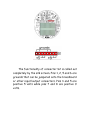
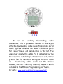
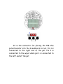
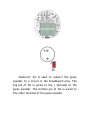
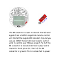
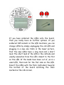
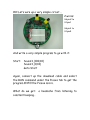
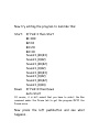
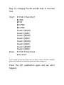
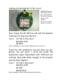
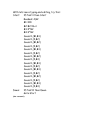
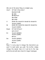
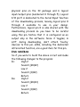
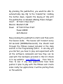
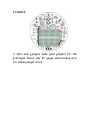
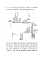
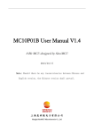
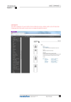
The AXEme PICaxe Construction Set
Now what do I do with it?
The first thing you have to do is to install the Picaxe
Program Development System on your computer. If you
have it already installed, you are good to go. If you don’t
have it, you will have to go get it and install it on your
computer. It is available as a free download at:
http://www.rev-ed.co.uk/picaxe
The Picaxe Programming Editor is quite large and is only
practical to download with a high speed connection. If
you don’t have a high speed connection, then you should
purchase the Picaxe 08-M Starter package which
includes the Picaxe Programming Editor on a CDrom and a
factory made downloading cable. Once you have the
Programming Editor installed, you will then have to
configure it for the computer port that you will be using
to download programs into the Picaxe micro. The full
Picaxe reference manual is available under the help tab in
the Editor. This User’s guide will start you on the road to
using the PICaxe Construction Set for building prototype
PICaxe circuits. It is NOT a substitute for reading the
PICaxe manual that is included in the PICaxe
Programming System Help Tab. Make sure you have a
properly configured Picaxe Programming Editor installed
on your computer before you attempt to try the
examples in this guide. These examples are typed into
the Editor and then downloaded into the micro to run.
You can run through the examples given here without
knowing anything about the actual commands comprising
the Picaxe Instruction set. Read through the getting
started section under the Help tab and familiarize
yourself with the editing and downloading operations
within the Picaxe Programming Editor. Now for the stuff
pertinent to the QRPme AXEme construction set…..
Let’s learn what all the connector functions are…
The connector marked S1 brings out all 8 pins of
the PICaxe socket U1 to an 8 pin SIP socket for
routing the various signals into the prototype
circuit.
S1 Pin Picaxe Pin
1
2
3
4
5
6
7
8
8
1
7
6
5
4
3
2
Picaxe Function
Ground
+5 volts
Out 0, IRout, Serial out
Out 1, In 1, ADC 1
Out 2, In 2, ADC 2, PWM 2, Tune
In 3
Out 4 / In 4
Serial in
The functionality of connector S2 is called out
completely by the silk screen. Pins 1, 2, 5 and 6 are
grounds that can be jumpered onto the breadboard
or other input/output connectors. Pins 3 and 5 are
positive 5 volts while pins 7 and 8 are positive 9
volts.
S3 is an auxiliary downloading cable
connection. The 3 pin Molex header is where you
attach a downloading cable made from an old serial
cable. QRPme includes the Molex connector parts
for converting an old serial cable in this kit. The
user must supply the cable. Pin 1, indicated by the
box, is serial out while pin 2 is serial in and pin 3 is
ground. For full details on wiring an old serial cable
as a downloading cable, check out the PICaxe
Manual, Section 1: Getting Started, page 27, which
included in the PICaxe Programming Software.
Or goto: www.reved.co.uk/docs/picaxe_manual1.pdf
S4 is the connector for placing the 10K ohm
potentiometer into the breadboard circuit. Pin 1 is
connected to the right end of the pot. Pin 2 is
connected to the wiper while pin 3 is connected to
the left end of the pot.
S5 is the connected to the un-configured RCA
connector J2. The right pin of S5, Pin 1, is
connected to the center pin of the RCA connector.
The left pin of S5, Pin 2, is connected to the outer
shield of the RCA connector.
Connector S6 is used to connect the piezo
sounder to a circuit in the breadboard area. The
top pin of S6 is wired to the + terminal of the
piezo sounder. The bottom pin of S6 is wired to
the other terminal of the piezo sounder.
S7 Pin
5
L
L
O
I
S
S
G
Function
+5 volts
Left LED LED is on when pin is low
Right LED LED is on when pin is low
One wire input/output to temp. sensor
Infrared input from IR decoder
Left pushbutton switch
Right pushbutton switch
Ground
Use the appropriate S7 pin to connect the
desired sensor or function to either the PICaxe or
prototype circuits.
The IR connector is used to decode the infrared
signals from a SONY compatible remote control
unit. Install the supplied IR decoder chip and you
can use SONY format infrared remote control
units to control your PICaxe project. Pin 1 of the
IR connector is decoded infrared output and is
routed to the I pin on S7. Pin 2 of the IR
connector is ground. Pin 3 is connected to power.
If you have soldered the LEDs onto the board,
then you really have no further options. If you
soldered SIP sockets in the LED locations, you can
change LEDs by simply unplugging the old LED and
plugging in a new one. Note in the lower picture,
that the new LEDs have a long lead and a short
lead. The short lead of the LED is the cathode and
usually emanates from the LED closest to the flat
on the LED. If the leads have been cut of, as in a
used LED, then look for the flat side on the LED.
Insert the LEDs with the flats (cathodes) towards
the bottom of the board matching the flats
marked on the silk screen.
The two jumpers, marked J, connect +5 volts and
ground to the appropriate pins on connector S1
and, hence, the PICaxe micro. Pull the jumpers out
and now the 8 pins of the socket U1 go to the same
pins on S1 as before but are now isolated from
power and ground. This allows you to insert other
chips in socket U1 that don’t want to see +5 volts
on pin 1 and ground on pin 8. LM386 amplifier chips,
LM555 programmable timer chips and NE602 chips
are examples of chips that can be used in the U1
socket and then connected to prototype circuits on
the breadboard area using connector S1. Don’t
forget to reinstall the jumpers when you switch
back to the PICaxe micro…
OK! Let’s wire up a very simple circuit….
2 wires:
S6 pin2 to
S1 pin1
S6 pin1 to
S1 pin4
And write a very simple program to go with it:
Start:
Sound 1,(100,10)
Sound 1,(0,10)
Goto Start
Again, connect up the download cable and select
the RUN command under the Picaxe tab to get the
program INTO the Picaxe micro.
What do we get:
constant beeping…
a headache from listening to
Let’s add another wire.
Start:
Down:
S1 pin5 to S7 pin6
If Pin2=1 then Start
Sound 1,(100,10)
If Pin2=0 then Down
Goto Start
Again, select the Run command under the Picaxe
tab to get the program INTO the Picaxe micro…
What do we have now? Press the left pushbutton
switch and see…
Now try editing the program to look like this:
Start:
Down:
If Pin2=1 then Start
B1=100
B2=10
B3=20
B4=30
Sound 1,(B1,B3)
Sound 1,(0,B2)
Sound 1,(B1,B2)
Sound 1,(0,B2)
Sound 1,(B1,B3)
Sound 1,(0,B2)
Sound 1,(B1,B2)
Sound 1,(0,B4)
If Pin2=0 then Down
Goto Start
Of course, it is left unsaid that you have to select the Run
command under the Picaxe tab to get the program INTO the
Picaxe micro…
Now press the left pushbutton and see what
happens…
Now try changing the B3 and B4 lines to look like
this…
Start:
Down:
If Pin2=1 then Start
B1=100
B2=10
B3=2*B2
B4=3*B2
Sound 1,(B1,B3)
Sound 1,(0,B2)
Sound 1,(B1,B2)
Sound 1,(0,B2)
Sound 1,(B1,B3)
Sound 1,(0,B2)
Sound 1,(B1,B2)
Sound 1,(0,B4)
If Pin2=0 then Down
Goto Start
I will remind you one more time that you have to select the Run command
under the Picaxe tab to load the program into the Picaxe micro…
Press the left pushbutton again and see what
happens…
Adding a potentiometer to the circuit.
Add these wires:
1K resistor from S7
pin 1 to protoboard
S4 pin 3 to the same
row as the 1K
resistor
S4 pin 2 to S1 pin 7
S4 pin 1 to S7 pin 7
Now change the B1=100 line and add the Readadc
statement so they look like this…
Start: If Pin2=1 then Start
Readadc 4,B1
B1=B1/2
(OK I lied! Remember to select the Run command under the Picaxe tab…)
Press the left pushbutton and see what you get.
Rotate the pot shaft a little and press the
pushbutton again. Experiment with different pot
settings. Now make these changes to the program
and see what happens :
Start: If Pin2=1 then Start
Readadc 4,B2
B1=100
B2=B2/16+1
(Did you remember to select the Run command you know where…)
With lots more typing and editing, try this:
Start:
If Pin2=1 then Start
Readadc 4,B2
B1=100
B2=B2/16+1
B3=2*B2
B4=3*B2
Sound 1,(B1,B3)
Sound 1,(0,B2)
Sound 1,(B1,B2)
Sound 1,(0,B2)
Sound 1,(B1,B3)
Sound 1,(0,B2)
Sound 1,(B1,B2)
Sound 1,(0,B4)
Sound 1,(B1,B3)
Sound 1,(0,B2)
Sound 1,(B1,B3)
Sound 1,(0,B2)
Sound 1,(B1,B2)
Sound 1,(0,B2)
Sound 1,(B1,B3)
Sound 1,(0,B4)
Down:
If Pin2=0 then Down
Goto Start
(Run command?)
We can do the same thing in a simpler way:
Start: If Pin2=1 then Start
Readadc 4,B2
B1=100
B2=B2/16+1
B3=2*B2
B4=3*B2
C:
Gosub Da: Gosub Di: Gosub Da: Gosub Di
Sound 1,(0,B4)
Q:
Gosub Da: Gosub Da: Gosub Di: Gosub Da
Sound 1,(0,B4)
Down: If Pin2=0 then C
Goto Start
Di:
Sound 1,(B1,B2)
Sound 1,(0,B2)
Return
Da:
Sound 1,(B1,B3)
Sound 1,(0,B2)
Return
(Run?)
Now it is very easy to change the characters you
want to send when you push the button; simply
change the Gosub lines at C and Q to the new
patterns and add more lines for longer messages.
If you also have a Two Tinned Tunas kit, find
another 1K ohm resistor and a 2N2222A from your
junk box and add this circuitry:
SIDEBAR:
Note the confusing terminology at the input signal
box…… S1 pin5 is the PHYSICAL address of the
signal…you CONNECT the wire to Pin 5 on
connector S1.
Pin 2, in the box, refers to the
LOGICAL address of the signal. In your programs,
you would refer to this signal by Pin2. Computers
like to start counting things at 0 and computer
chips have leads, commonly referred to as pins,
that start with pin 1. To further complicate
matters, power and ground signals have to enter
micro chips thru 2 pins as decided by the engineers
who designed them, so LOGICAL pins referred to
by micros hardly ever match up with the
PHYSICAL pins where they enter or leave the
micro chip. The PICaxe 08-M microprocessor has 8
physical pins on the IC package and 6 logical
input/output pins (numbered 0 through 5). Logical
I/O pin 5 is dedicated to the Serial Input function
of the downloading process, leaving logical pins 0
through 4 available to use in your design.
Furthermore, logical pin 0 is also shared with the
downloading process so you have to be careful
using this pin. Notice that it is configured as an
output only in the software. Since it toggles, A
LOT, during downloading, don’t attach ‘touchy’
devices to this pin. LEDs, including the dedicated
infrared led function, are a good item for this pin.
END SIDEBAR
So if you were to build the above circuit and make
the following changes to the program:
Di:
High 2
Sound 1,(B1,B2)
Low 2
Sound 1,(0,B2)
Return
Da:
High 2
Sound 1,(B1,B3)
Low 2
Sound 1,(0,B2)
Return
By pressing the pushbutton, you would be able to
automatically key CQ to the transmitter. Holding
the button down, repeats the keying of CQ until
the pushbutton is released. Making these changes:
Start: If Pin2=1 then Start
Beacon: Readadc 4,B2
Down: If Pin2=0 then Start
Pause 60000
Goto Beacon
Now pressing the pushbutton starts and then exits
the beacon mode. The beacon will transmit every
60 seconds (60000milliseconds). You should read
through the PICaxe manual included in the Help
section in the Programming Editor. I can only get
you started, you have to play and experiment with
all the software commands and how they can be
used with the hardware provided in this kit. Check
in to my website: www.QRPme.com from time to
time to see if any new applications have been
posted. I plan to play with the PICaxe and create
some really fun applications. I will be posting them
on the website.
A couple more notes:
1. When connecting circuits to a +5 volt pin, make
sure whatever you are connecting will NOT create
a low resistance path directly to ground. High
currents resulting from low resistance parts from
ground can damage the voltage regulators.
EXAMPLE:
When we added the potentiometer in one of
the previous examples, we added a 1K ohm resistor
in series with the pot when we attached to pot to
the +5 volt pin. If the wiper of the pot is up at the
+5 volt end and it accidentally is connected to a
very low resistance circuit, the current is still
within reason. The 1K ohm resistor could also have
been inserted into the wiper circuit.
2. Instead of constantly inserting and removing
jumper wires each time you prototype a circuit, you
could pick the 4 corners and feed +5 to the two
‘top’ corners and ground to the 2 ‘bottom’ corners
and leave them there, making it easier next time to
wire something up.
EXAMPLE:
3. Zero ohm jumpers make good jumpers for the
prototype board. Use 22 gauge solid hookup wire
for making longer wires.
4. Here is a handy dandy ‘cheat sheet’ for all the
connectors and their corresponding functions.
So go to it! Read the Getting Started section of
the manual to learn about the general operation of
the PICaxe and then read the Command section to
see what commands are available for you to use.
Then try out the Interfacing section. Here is
where the PICaxe Construction Set can really help
you get up to speed as to what you can do with this
versatile little micro.
Check into the QRPme website:
www.QRPme.com
Projects and programs using the
Picaxe Construction Set
will be posted there as they are developed.
Thank you for your purchase!
W1REX