1
BASIC COMMANDS
www.picaxe.com
Section 2
1
IMPORTANT!
This PDF is designed to be used with the shortcut links (document outline) visible on the left hand side.
Displaying these links makes it much easier to navigate through this manual!
revolution
(c) Revolution Education Ltd.
All rights reserved.
Web: www.picaxe.com
Version 7.9.2 10/2015
1
BASIC COMMANDS
www.picaxe.com
Section 2
2
Contents
Introduction. ................................................................................................... 5
PICAXE Software ............................................................................................... 5
Labels ............................................................................................................ 6
Comments ....................................................................................................... 6
Constants ........................................................................................................ 7
Symbols .......................................................................................................... 7
Pre-Processor and Directives .............................................................................. 8
Variables - General ......................................................................................... 13
Variables - Storage ......................................................................................... 14
Variables - Scratchpad .................................................................................... 15
Variables - System .......................................................................................... 16
Variables - Special function ............................................................................. 17
Variables - Mathematics .................................................................................. 25
Variables - Unary Mathematics ......................................................................... 28
Input / Output Pin Naming Conventions ........................................................... 30
adcconfig ...................................................................................................... 31
adcsetup ....................................................................................................... 32
backward ...................................................................................................... 37
bcdtoascii ..................................................................................................... 38
bintoascii ..................................................................................................... 39
booti2c ........................................................................................................ 40
branch .......................................................................................................... 42
button .......................................................................................................... 43
calibadc (calibadc10) ..................................................................................... 45
calibfreq ....................................................................................................... 46
clearbit ......................................................................................................... 47
compsetup .................................................................................................... 48
count ........................................................................................................... 53
daclevel ........................................................................................................ 54
dacsetup ....................................................................................................... 55
debug ........................................................................................................... 57
dec ............................................................................................................. 58
disablebod .................................................................................................... 59
disabletime ................................................................................................... 60
disconnect .................................................................................................... 61
do...loop ...................................................................................................... 62
doze ............................................................................................................. 63
eeprom (data) ............................................................................................... 64
enablebod ..................................................................................................... 65
enabletime .................................................................................................... 66
end ............................................................................................................. 67
exit ............................................................................................................. 68
for...next ...................................................................................................... 69
forward ......................................................................................................... 70
fvrsetup ........................................................................................................ 71
get ............................................................................................................. 72
gosub (call) .................................................................................................. 73
goto ............................................................................................................. 74
hi2cin .......................................................................................................... 75
hi2cout ........................................................................................................ 77
hi2csetup ..................................................................................................... 79
hi2csetup - slave mode (X2 parts only) ............................................................. 79
hi2csetup - master mode ................................................................................. 81
halt ............................................................................................................. 83
hibernate ...................................................................................................... 84
high ............................................................................................................. 86
high portc ..................................................................................................... 87
hintsetup ...................................................................................................... 88
hpwm ........................................................................................................... 89
revolution
(c) Revolution Education Ltd.
All rights reserved.
Web: www.picaxe.com
Version 7.9.2 10/2015
2
BASIC COMMANDS
www.picaxe.com
Section 2
3
hpwmduty ..................................................................................................... 93
hserin ........................................................................................................... 94
hserout ......................................................................................................... 96
hsersetup ...................................................................................................... 97
hspiin (hshin) ............................................................................................... 99
hspiout (hshout) .......................................................................................... 100
hspisetup .................................................................................................... 101
i2cslave ...................................................................................................... 105
if...then \ elseif...then \ else \ endif .............................................................. 107
if...then {goto} ........................................................................................... 109
if...and/or..then {goto} ................................................................................ 109
if porta...then {goto} ................................................................................... 110
if portc...then {goto} ................................................................................... 110
if...then exit ............................................................................................... 111
if...and/or...then exit ................................................................................... 111
if...then gosub ............................................................................................ 112
if...and/or...then gosub ................................................................................ 112
inc ........................................................................................................... 114
infrain ........................................................................................................ 115
infrain2 ...................................................................................................... 117
infraout ...................................................................................................... 118
input .......................................................................................................... 123
inputtype ................................................................................................... 124
irin ........................................................................................................... 128
irout .......................................................................................................... 130
kbin ........................................................................................................... 132
keyin .......................................................................................................... 134
kbled (keyled) ............................................................................................. 136
let ........................................................................................................... 137
let dirs / dirsc = .......................................................................................... 139
let dirsA / dirsB / dirsC / dirsD = ................................................................... 140
let pins / pinsc = ......................................................................................... 141
let pinsA / pinsB / pinsC / pinsD = ................................................................. 142
lookdown .................................................................................................... 143
lookup ........................................................................................................ 144
low ........................................................................................................... 145
low portc .................................................................................................... 146
nap ........................................................................................................... 147
on...goto .................................................................................................... 148
on...gosub .................................................................................................. 149
output ........................................................................................................ 150
owin .......................................................................................................... 151
owout ........................................................................................................ 152
pause ......................................................................................................... 153
pauseus ...................................................................................................... 154
peek ........................................................................................................... 155
peeksfr ....................................................................................................... 157
play ........................................................................................................... 158
poke ........................................................................................................... 159
pokesfr ....................................................................................................... 161
pop ........................................................................................................... 162
popram ....................................................................................................... 164
pullup ........................................................................................................ 165
pulsin ......................................................................................................... 166
pulsout ....................................................................................................... 167
push .......................................................................................................... 168
pushram ..................................................................................................... 170
put ........................................................................................................... 171
pwm ........................................................................................................... 172
pwmduty ..................................................................................................... 173
pwmout ...................................................................................................... 174
random ....................................................................................................... 177
read ........................................................................................................... 178
readadc ...................................................................................................... 179
readadc10 ................................................................................................... 180
readdac ...................................................................................................... 181
readdac10 ................................................................................................... 182
readi2c ....................................................................................................... 183
readinternaltemp ......................................................................................... 184
revolution
(c) Revolution Education Ltd.
All rights reserved.
Web: www.picaxe.com
Version 7.9.2 10/2015
3
BASIC COMMANDS
www.picaxe.com
Section 2
4
readfirmware ...............................................................................................
readmem .....................................................................................................
readtable ....................................................................................................
readoutputs ................................................................................................
readportc ....................................................................................................
readrevision ................................................................................................
readsilicon ..................................................................................................
readtemp ....................................................................................................
readtemp12 .................................................................................................
readowclk ...................................................................................................
resetowclk ...................................................................................................
readowsn ....................................................................................................
reconnect ...................................................................................................
reset ..........................................................................................................
restart ........................................................................................................
resume .......................................................................................................
return .........................................................................................................
reverse .......................................................................................................
rfin ...........................................................................................................
rfout ..........................................................................................................
run ...........................................................................................................
select case \ case \ else \ endselect ...............................................................
serin ..........................................................................................................
serrxd .........................................................................................................
serout ........................................................................................................
sertxd .........................................................................................................
servo ..........................................................................................................
servopos .....................................................................................................
setbit .........................................................................................................
setint .........................................................................................................
setintflags ..................................................................................................
setfreq ........................................................................................................
settimer ......................................................................................................
shiftin (spiin) ..............................................................................................
shiftout (spiout) ..........................................................................................
sleep ..........................................................................................................
sound .........................................................................................................
srlatch ........................................................................................................
srset / srreset ..............................................................................................
stop ...........................................................................................................
suspend ......................................................................................................
swap ..........................................................................................................
switch on/off ..............................................................................................
symbol .......................................................................................................
table ..........................................................................................................
tablecopy ....................................................................................................
tmr3setup ...................................................................................................
toggle ........................................................................................................
togglebit ....................................................................................................
touch .........................................................................................................
touch16 ......................................................................................................
tune ...........................................................................................................
uniin ..........................................................................................................
uniout ........................................................................................................
wait ...........................................................................................................
write ..........................................................................................................
writemem ....................................................................................................
writei2c ......................................................................................................
Appendix 1 - Commands ................................................................................
Appendix 2 - Additional (non-command) reserved words ...................................
Appendix 3 - Reserved Labels ........................................................................
Appendix 4 - Possible Conflicting Commands ...................................................
Appendix 5 - X2 Variations ............................................................................
Appendix 6 - M2 Variations ...........................................................................
Manufacturer Website: ..................................................................................
Trademark: ..................................................................................................
Acknowledgements: ......................................................................................
revolution
(c) Revolution Education Ltd.
All rights reserved.
186
187
188
189
190
191
192
193
194
195
196
197
199
200
201
202
203
204
205
207
209
212
213
216
217
219
220
222
223
224
228
230
232
234
237
239
240
241
243
244
245
246
247
248
249
250
251
253
254
255
256
259
266
267
269
270
271
272
273
274
275
276
277
278
279
279
279
Web: www.picaxe.com
Version 7.9.2 10/2015
4
BASIC COMMANDS
www.picaxe.com
Section 2
5
BASIC COMMANDS
Introduction.
The PICAXE manual is divided into four sections:
Section 1 Getting Started
Section 2 BASIC Commands
Section 3 Microcontroller interfacing circuits
Section 4 Flowcharts
This second section provides the syntax (with detailed examples) for all the BASIC
commands supported by the PICAXE system. It is intended as a lookup reference guide
for each BASIC command supported by the PICAXE system. As some commands only
apply to certain size PICAXE chips, a diagram beside each command indicates the sizes
of PICAXE that the command applies to.
When using the flowchart method of programming, only a small subset of the available
commands are supported by the on-screen simulation. These commands are indicated
by the corresponding flowchart icon by the description.
For more general information about how to use the PICAXE system, please see section 1
‘Getting Started’.
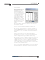
PICAXE Software
The main Windows application used for programming the PICAXE chips is called the
‘PICAXE Editor’. This software is free of charge to PICAXE users.
Please see section 1 of the manual (‘Getting Started’) for installation details and
tutorials. Please ensure that you are using the latest version, the software is a free
download from www.picaxe.com/PE
PICAXE Editor 6 is also a flowcharting application designed for educational use (it
replaces Logicator). Programs are developed as graphical flowcharts on screen. These
flowcharts are then automatically converted into BASIC files for download into the
PICAXE chips.
AXEpad is a simpler free version of the Programming Editor software for use on the
Linux and Mac operating systems. It also supports all the BASIC commands in this
manual.
PICAXE VSM is a Berkeley SPICE circuit simulator, which will simulate complete
electronic circuits using PICAXE chips. The BASIC program can be stepped through line
by line whilst watching the input/output peripheral react to the program.
The latest version of the software is available on the PICAXE website at
www.picaxe.com
If you have a question about any command please post a question on the very active
support forum at this website
www.picaxeforum.co.uk
revolution
(c) Revolution Education Ltd.
All rights reserved.
Web: www.picaxe.com
Version 7.9.2 10/2015
5
BASIC COMMANDS
www.picaxe.com
Section 2
6
Labels
08
08M
08M2
14M
14M2
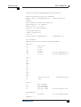
Labels are used as markers throughout the program. Labels are used to mark a
position in the program to ‘jump to’ from another position using a goto, gosub
or other command. Labels can be any word (that is not already a reserved
keyword) and may contain digits and the underscore character. Labels must start
with a letter or underscore (not digit), and are followed directly by a colon (:) at
the marker position. The colon is not required within the actual commands.
The compiler is not case sensitive (lower and/or upper case may be used at any
time).
Example:
18
18A
18M
18M2
18X
28A
28X
28X1
28X2
40X
40X1
40X2
main:
high B.1
pause 5000
low B.1
pause 5000
goto main
;
;
;
;
;
switch on output 1
wait 5 seconds
switch off output 1
wait 5 seconds
loop back to start
Whitespace
Whitespace is the term used by programmers to define the white area on a
printout of the program. This involves spaces, tabs and empty lines. Any of these
features can be used to space the program to make it clearer and easier to read.
It is convention to only place labels on the left hand side of the screen. All other
commands should be indented by using the ‘tab key’. This convention makes the
program much easier to read and follow.
Newline
Commands are normally placed on separate lines. However if desired the colon
(:) character can be use to separate multiple commands on a single line e.g.
if pin1 = 1 then : high 1 : else : low 1 : endif
Line continuation
Long lines can be continued onto a second line by using an underscore e.g.
if pin1 = 1 then gosub _
label1 ; continued on second line
Code Collapsing
On long programs in Programming Editor the { and } brackets can be used to
collapse (“hide”) sections of code to make programs clearer e.g.
{
high 1
}
Comments
Comments are used to add information into the program for future reference.
They are completely ignored by the computer during a download. Comments
begin with an apostrophe (‘) or semicolon (;) and continue until the end of the
line. The keyword REM may also be used for a comment.
revolution
(c) Revolution Education Ltd.
All rights reserved.
Web: www.picaxe.com
Version 7.9.2 10/2015
6
BASIC COMMANDS
www.picaxe.com
Section 2
08
08M
08M2
7
Multiple lines can be commented by use of the #REM and #ENDREM directives.
Examples:
high 0
; make output 0 high
low 0
REM make output 0 low
#rem
high 0
pause 2000
#endrem
14M
14M2
; #rem out a number of lines
Constants
18
18A
18M
18M2
18X
20M
20M2
20X2
Constants are ‘fixed’ numbers that are used within the program. The software
supports word integers (any whole number between 0 and 65535).
Constants can be declared in four ways: decimal, hex, binary and ASCII.
Decimal
Hexadecimal (hex)
Binary
ASCII text strings
numbers are typed directly without any prefix.
numbers are preceded with a dollar-sign ($) or (0x).
numbers are preceded by a percent-sign (%).
are enclosed in quotes (“).
Examples:
100
$64
0x64
%01100100
“A”
“Hello”
B1 = B0 ^ $AA
;
;
;
;
;
;
;
100 decimal
64 hex
64 hex
01100100 binary
“A” ascii (65)
“Hello” - equivalent to “H”,”e”,”l”,”l”,”o”
xor variable B0 with AA hex
Symbols
28A
28X
28X1
28X2
Symbols can be assigned to constant values, and can also be used as alias names
for variables (see Variables overleaf for more details). Constant values and
variable names are assigned by following the symbol name with an equal-sign
(=), followed by the variable or constant. Symbols can use any word that is not a
reserved keyword (e.g. switch, step, output, input, etc. cannot be used)
Symbols can contain numeric characters and underscores (flash1, flash_2 etc.)
but the first character cannot be numeric (e.g. 1flash). Simple constant maths is
also available. See the symbol command entry later in this manual for more
information. The use of symbols does not increase program length.
40X
40X1
40X2
Example:
symbol RED_LED = B.7
symbol COUNTER = b0
let COUNTER = 200
mainloop:
high RED_LED
pause COUNTER
low RED_LED
pause COUNTER
goto mainloop
revolution
(c) Revolution Education Ltd.
All rights reserved.
;
;
;
;
;
;
;
;
;
;
define a constant symbol
define a variable symbol
preload variable with value 200
define a program address
address symbol end with colons
switch on output B.7
wait 0.2 seconds
switch off output B.7
wait 0.2 seconds
loop back to start
Web: www.picaxe.com
Version 7.9.2 10/2015
7
BASIC COMMANDS
www.picaxe.com
Section 2
8
Pre-Processor and Directives
08
08M
08M2
14M
14M2
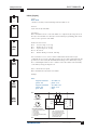
The main purposes of the PICAXE Pre Processor are
1) To allow BASIC programs to be split over multiple files
2) To allow macros (user defined functions)
3) To allow multiple word string replacement e.g. myhighC(x) = high portC x
The pre-processor takes one or more input files, combines them together,
substitutes and processes any macros, and then generates a single output file
which is then passed to the standard PICAXE compiler. If desired end users can
view the final pre-processor output code via the File>Options>Diagnostics tab.
18
18A
18M
18M2
18X
Preprocessor Directives
Directives have a hash/pound (#) symbol as the first non-blank character of a
line, and are immediately followed by the directive keyword.
There are two main types of directive, those used by the pre-processor and those
used by the compiler. The pre-processor simply ignores compiler directives.
The following is a list of all the pre-processor directives.
20M
20M2
20X2
28A
28X
28X1
28X2
40X
40X1
40X2
#PICAXE
Define the PICAXE type.
This must match the Workspace Explorer setting.
#INCLUDE Include and merge a specified file, which generally
has a .basinc file extension.
#DEFINE
Define a single line symbol
#MACRO/#ENDMACRO
Define a multiline symbol or macro
#UNDEF
Undefine a previously defined symbol/macro
#IF
Process next block if symbol/calculation is true
#IFDEF
Process next block if symbol is defined
#IFNDEF
Process next block if symbol is not defined
#ELSEIF
Process next block if symbol/calculation is true
#ELSEIFDEF Process next block if symbol is defined
#ELSE
Process next block if previous blocks have not been processed.
#ENDIF
Terminate a conditional block
#REM
Start commenting a section of code
#ENDREM
Finish commenting of a section of code
#ERROR
Force an error at the current position
Further examples of use are given at the end of this section.
revolution
(c) Revolution Education Ltd.
All rights reserved.
Web: www.picaxe.com
Version 7.9.2 10/2015
8
BASIC COMMANDS
www.picaxe.com
Section 2
9
Compiler Directives
The following is a list of compiler directives. These directives are simply ignored
by the pre-processor.
Compiler Directives:
#NO_DEBUG
Do not output any debug commands within the program.
#no_debug
#NO_END
Do not add the automatic END command at end of file
#no_end
#TITLE
Set a title for the remote download tool
#title “This is my program”
#REVISION
Set a file version number
#revision 1
Compiler/Downloader module directives:
#SLOT
Define the target program slot
#slot 1
#COM
Select the COM port for downloading (overrides the
Workspace Explorer)
#com 1
#com /dev/ttyUSB0
#NO_DATA
Do not download EEPROM data
#no_data
#NO_TABLE
Do not download TABLE data
#no_table
#TERMINAL
Open the terminal at a specified baud rate
#terminal 9600
#terminal off
#FREQ
Set freq for obsolete old parts
#freq 8
Presentation Directive:
#REGION/#ENDREGION
Define a collapsing block region
Deprecated in PE6
#GOSUBS
- Now select special compiler via File>Options>Compilers
#SIMTASK
- Now select Simulation on Workspace Explorer
#SIMSPEED - Now simply use the simulation speed slider bottom right of
statusbar
revolution
(c) Revolution Education Ltd.
All rights reserved.
Web: www.picaxe.com
Version 7.9.2 10/2015
9
BASIC COMMANDS
www.picaxe.com
Section 2
10
Pre-processor Variable String Substitutions
The following predefined pre-processor string variables will substitute as follows
during pre-processing. Time and dates are based upon the computer’s system
clock.
ppp_date
ppp_date_uk
ppp_date_us
ppp_datetime
ppp_time
ppp_filename
ppp_filepath
“YYYY-MM-DD”
“DD-MM-YYYY”
“MM-DD-YYYY”
"YYYY-MM-DD HH:MM:SS"
"HH:MM:SS"
The short filename of the main BASIC inputfile
The full filename and path of the main BASIC inputfile
Example of use:
sertxd (“Filename: ”, ppp_filename)
sertxd (“Downloaded: ”, ppp_datetime)
#INCLUDE “filename.basinc”
The #INCLUDE directive opens and processes a file, then continues processing
the original file. A file opened through the #INCLUDE directive can itself contain
other #INCLUDE directives. There is no limit to the number of files that can be
nested.
The filename must be enclosed within double quotes and can use an absolute or
relative filepath. If the path is relative the pre-processor will attempt to locate the
file in these folders in this order:
1)
the folder of the main top-level file
2)
each folder identified by the Windows %Path% Environment Variable
Included files are normally named with a .basinc extension, but may also be .bas
files. There is no difference between the format of the files apart from the
filename extension.
The advantages of using the .basinc extension for include files are:
1) PE6 disables the Syntax Check/Program, buttons on this file type, so that you
don’t accidentally try to compile an include file by itself
2) PE6 automatically saves any open .basinc files on each compile of the main
program. This is to ensure that any changes made on screen to the included
file are correctly included within the compile.
3) Other PICAXE users will recognise the file as an include file .Included files
must be saved as ASCII or UTF-8 Unicode files with a line ending type CR or
CR-LF (not LF only).
As the compiler processes ’top-to-bottom’ on the pre-processor output file it is
necessary to take care to ‘skip’ the #INCLUDE file (if necessary) when it is
included at the top of a program.
Reset_here:
#INCLUDE
Init:
revolution
Goto Init
“sphero.basinc”
; jump over include file
; start program here
(c) Revolution Education Ltd.
All rights reserved.
Web: www.picaxe.com
Version 7.9.2 10/2015
10
BASIC COMMANDS
www.picaxe.com
Section 2
11
#DEFINE and #MACRO
#DEFINE is used to define directive symbols that are then used within the preprocessing.
Do not confuse with ‘symbol xxx = yyy’ type symbols which are used by the
compiler within the main program. The pre-processor cannot use or even
recognise ‘symbol xxx = ‘ defined symbols.
#MACRO/#ENDMACRO (or #ENDM if you are lazy typist) is simply the
multiline version of #DEFINE
Examples of use:
1) Simple symbol definition for use with #IFDEF/#IFNDEF:
#DEFINE SPHERO
2) String substitution:
#DEFINE MAGIC_NUMBER
#DEFINE SpheroWakeUp
#DEFINE SetBackLedOn
#DEFINE SetBackLedOff
"0006664A3BFB"
Gosub Sphero_Initialise
b0 = 255 : Gosub SendBackLED
b0 = 0 : Gosub SendBackLED
3) Numeric value substitution:
#DEFINE PROGRAM_VERSION
#DEFINE PORT_VALUE
#DEFINE FALSE
#DEFINE TRUE
22
%10101010
0
1
4) Substitution of another macro
#DEFINE
#DEFINE
#DEFINE
#DEFINE
SetRgbColorOff
SetRgbColorRed
SetRgbColorGreen
SetRgbColorBlue
SetRgbColor(0, 0, 0)
SetRgbColor(255, 0, 0)
SetRgbColor(0, 255, 0)
SetRgbColor(0, 0, 255)
5) Passing parameters that are then used with the substitution
#MACRO SetRgbColor(R, G, B)
b0 = R
b1 = G
b2 = B
Gosub SendRGB
#ENDMACRO
#DEFINE SetHeading(H)
revolution
(c) Revolution Education Ltd.
All rights reserved.
w0 = H : Gosub SendHeading
Web: www.picaxe.com
Version 7.9.2 10/2015
11
BASIC COMMANDS
www.picaxe.com
Section 2
12
#MACRO SetHeadingSpeed(H, S)
w1 = H
b0 = S
Gosub SendHeadingSpeed
#ENDMACRO
Parameters can be defined using any word that starts with a letter and is not
already a BASIC keyword.
Conditional processing.
Processing can be conditional upon use of the #IFDEF/#IFNDEF/#IF directives.
#IFDEF name
Process if the name symbol has been defined
#IFNDEF name
Process if the symbol has not been defined
#IF name
Process if the symbol has a true (not 0) value
#IF name> constant Process if the numeric constant calculation is true
The supported operators are =, <>, >, >=, <, <=
Multiple tests can be made using the #ELSEIF and #ELSEIFDEF directives, and a
single optional #ELSE may also be used before the #ENDIF e.g.
#IF name > 10
#ELSEIF name > 5
#ELSE
#ENDIF
or using multiple defined symbols
#IFDEF name1
#ELSEIFDEF name2
#ELSEIFNDEF name3
#ELSE
#ENDIF
Forced Errors
#ERROR “This code is incomplete!”
The #ERROR forces the pre-processor to stop and output the error message.
revolution
(c) Revolution Education Ltd.
All rights reserved.
Web: www.picaxe.com
Version 7.9.2 10/2015
12
BASIC COMMANDS
www.picaxe.com
Section 2
13
Variables - General
08
08M
08M2
14M
14M2
18
18A
18M
18M2
18X
20M
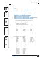
20M2
20X2
The RAM memory is used to store temporary data in variables as the program
runs. It loses all data when the power is removed or reset. There are four types of
RAM variables - general purpose, scratchpad, storage, and special function.
See the ‘let’ command for details about variable mathematics.
General Purpose Variables.
Bytes
X2 parts
56
X1 parts
28
M2 parts
28
Older parts 14
Bit Name
bit0-31
bit0-31
bit0-31
bit0-15
Byte Name
b0-55
b0-27
b0-27
b0-13
Word Name
w0-27
w0-13
w0-13
w0-6
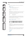
There are 14 (or more) general purpose byte variables. These byte variables are
labelled b0, b1 etc... Byte variables can store integer numbers between 0 and 255
inclusive. Byte variables cannot use negative numbers or fractions, and will
‘overflow’ without warning if you exceed the 0 or 255 boundary values (e.g. 254
+ 3 = 1) (2 - 3 = 255)
However for larger numbers two byte variables can be combined to create a word
variable, which is capable of storing integer numbers between 0 and 65535
inclusive. These word variables are labelled w0, w1, w2 etc... and are constructed
as follows:
w0
w1
w2
w3
etc...
=
=
=
=
b1 : b0
b3 : b2
b5 : b4
b7 : b6
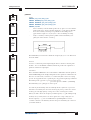
Therefore the most significant byte of w0 is b1, and the least significant byte of
w0 is b0.
28A
28X
28X1
28X2
40X
40X1
40X2
In addition there are up to 32 individual bit variables (bit0, bit1 etc..). These bit
variables can be used where you just require a single bit (0 or 1) storage
capability. Bit variables are part of the lower value byte variables e.g.
b0
b1
etc...
= bit7: bit6: bit5: bit4: bit3: bit2: bit1: bit0
= bit15: bit14: bit13: bit12: bit11: bit10: bit9: bit8
You can use any word, byte or bit variable within any mathematical assignment
or command that supports variables. However take care that you do not
accidentally repeatedly use the same ‘byte’ or ‘bit’ variable that is being used as
part of a ‘word’ variable elsewhere.
revolution
(c) Revolution Education Ltd.
All rights reserved.
Web: www.picaxe.com
Version 7.9.2 10/2015
13
BASIC COMMANDS
www.picaxe.com
Section 2
14
Indirect Addressing of General Purpose Variables (M2/X2 parts)
On these parts there are up to 256 general purpose variables. The lower bytes,
known as b0, b1, b2 etc upwards, can be used directly in any command (as with
all other PICAXE parts). All 256 bytes (0-255) can also be addressed both
directly and indirectly.
To directly address the values the peek (read the byte) and poke (write the byte)
commands are used. To indirectly address the values the virtual variable name
‘@bptr’ is used. @bptr is a variable name that can be used in any command (ie as
where a ‘b1’ variable would be used). However the value of the variable is not
fixed (as with b1) , but will contain the current value of the byte currently
‘pointed to’ by the byte pointer (bptr).
The compiler also accepts ‘@bptrinc’ (post increment) and ‘@bptrdec’ (post
decrement) .
Every time the ‘@bptrinc’ variable name is used in a command the value of the
byte pointer is automatically incremented by one (ie bptr = bptr+1 occurs
automatically after the read/write of the value @bptr). This makes it ideal for
storage of a single dimensional array of data.
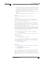
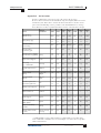
Variables - Storage
Storage variables are additional memory locations allocated for temporary storage
of byte data. They cannot be used in mathematical calculations, but can be used
to temporarily store byte values by use of the peek and poke commands.
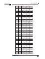
The number of available storage locations varies depending on PICAXE type. The
following table gives the number of available byte variables with their addresses.
These addresses vary according to technical specifications of the microcontroller.
See the poke and peek command descriptions for more information.
08M2
18M2
18M2+, 14M2, 20M2
99
227
483
28 to 127 ($1C to $7F)
28 to 255 ($1C to $FF)
28 to 511 ($1C to $1FF)
28X2, 40X2
200 56 to 255 ($38 to $FF)
20X2
72
56 to 127 ($38 to $7F)
All X1 parts
95
80 to 126 ($50 to $7E), 192 to 239 ($C0 to $EF)
All X1 and X2 parts also have the additional scratchpad memory, see next page.
Older discontinued parts:
All M parts
48
All A parts
48
18X
96
28X, 40X
112
08
none
revolution
80 to 127 ($50 to $7F)
80 to 127 ($50 to $7F)
80 to 127 ($50 to $7F), 192 to 239 ($C0 to $EF)
80 to 127 ($50 to $7F), 192 to 255 ($C0 to $FF)
(c) Revolution Education Ltd.
All rights reserved.
Web: www.picaxe.com
Version 7.9.2 10/2015
14
BASIC COMMANDS
www.picaxe.com
Section 2
15
Variables - Scratchpad
----
---
The scratchpad is a temporary memory area for storage of data such as arrays.
PICAXE-28X1, 40X1, 20X2 parts have 128 scratchpad bytes (0-127)
PICAXE-28X2, 40X2 parts have 1024 scratchpad bytes (0-1023)
To directly address the scratchpad values the get (read the byte) and put (write
the byte) commands are used.
To indirectly address the values the virtual variable name ‘@ptr’ is used. @ptr is a
variable name that can be used in any command (ie as where a ‘b1’ variable
would be used). However the value of the variable is not fixed (as with b1) , but
will contain the current value of the byte currently ‘pointed to’ by the pointer
(ptr).
------
--20X2
The compiler also accepts ‘@ptrinc’ (post increment) and ‘@ptrdec’ (post
decrement) . Every time the ‘@ptrinc’ variable name is used in a command the
value of the scratchpad pointer is automatically incremented by one (ie ptr =
ptr+1 occurs automatically after the read/write of the value @ptr). This makes it
ideal for storage of a single dimensional array of data.
ptr = 1
‘ reset scratchpad pointer to 1
serrxd @ptrinc,@ptrinc,@ptrinc,@ptrinc,@ptr
‘ serin 5 bytes to scratchpad addresses 1-5
ptr = 1
for b1 = 1 to 5
sertxd (@ptrinc)
next b1
‘ reset scratchpad pointer to 1
‘ re-transmit those 5 values
See the put and get commands for more details.
--28X1
28X2
-40X1
40X2
revolution
(c) Revolution Education Ltd.
All rights reserved.
Web: www.picaxe.com
Version 7.9.2 10/2015
15
BASIC COMMANDS
www.picaxe.com
Section 2
16
Variables - System
--08M2
-14M2
---18M2
--
The M2 parts have 8 word variables which are reserved for system hardware use.
However if that piece of system hardware is not used within a program the
variables may be used as general purpose variables.
s_w0
s_w1
s_w2
s_w3
s_w4
s_w5
s_w6
s_w7
task
time
current task (during parallel processing)
reserved for future use
reserved for future use
reserved for future use
reserved for future use
reserved for future use
reserved for future use
elapsed time
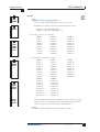
The X1 and X2 parts have 8 word variables and 1 flags byte which are reserved for
system hardware use. However if that piece of system hardware is not used within
a program the variables may be used as general purpose variables.
-20M2
20X2
s_w0
s_w1
s_w2
s_w3
s_w4
s_w5
s_w6
s_w7
adcsteup2
timer3
compvalue
hserptr
hi2clast
timer
reserved for future use
reserved for future use
high word of adcsetup (28X2 only)
timer3 value (X2 only)
comparator results (X2 only)
hardware serin pointer
hardware hi2c last byte written (slave mode)
timer value
The ‘flags’ byte variable is made up of 8 bit variables
--28X1
28X2
-40X1
40X2
flag0
flag1
flag2
flag3
flag4
flag5
flag6
flag7
revolution
hint0flag
hint1flag
hint2flag
hintflag
compflag
hserflag
hi2cflag
toflag
X2 only - interrupt on B.0
X2 only - interrupt on B.1
X2 only - interrupt on B.2
X2 only - interrupt on any of above
X2 only - occurs on any comparator change
hserial background receive has occurred
hi2c write has occurred (slave mode)
timer overflow flag
(c) Revolution Education Ltd.
All rights reserved.
Web: www.picaxe.com
Version 7.9.2 10/2015
16
BASIC COMMANDS
www.picaxe.com
Section 2
17
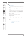
Variables - Special function
The special function variables available for use depend on the PICAXE type:
08
08M
08M2
PICAXE-08 / 08M / 08M2 Special Function Registers
pins = the input / output port
dirs
= the data direction register (sets whether pins are inputs or outputs)
infra = another term for variable b13, used within the 08M infrain2 command
Additional 08M2 Special Function Registers
bptr
- the byte RAM pointer
@bptr
- the byte RAM value pointed to by bptr
@bptrinc
- the byte RAM value pointed to by bptr (post increment)
@bptrdec
- the byte RAM value pointed to by bptr (post decrement)
time
- the current time (seconds counter at 4MHz or 16MHz)
task
- the current task
The variable pins is broken down into individual bit variables for reading from
individual inputs with an if...then command. Only valid input pins are
implemented.
pins
= x : x : x : pin4 : pin3 : pin2 : pin1 : x
The variable dirs is also broken down into individual bits.
Only valid bi-directional pin configuration bits are implemented.
dirs
revolution
= x : x : x : dir4 : x : dir2 : dir1 : x
(c) Revolution Education Ltd.
All rights reserved.
Web: www.picaxe.com
Version 7.9.2 10/2015
17
BASIC COMMANDS
www.picaxe.com
Section 2
18
PICAXE-14M2 / 18M2 / 20M2 Special Function Registers
-14M2
---18M2
--
-20M2
--
pinsB
outpinsB
dirsB
pinsC
outpinsC
dirsC
bptr
@bptr
@bptrinc
@bptrdec
time
task
- the portB input pins
- the portB output pins
- the portB data direction register
- the portC input pins
- the portC output pins
- the portC data direction register
- the byte RAM pointer
- the byte RAM value pointed to by bptr
- the byte RAM value pointed to by bptr (post increment)
- the byte RAM value pointed to by bptr (post decrement)
- the current time (seconds counter at 4MHz or 16MHz)
- the current task
When used on the left of an assignment ‘pins’ applies to the ‘output’ pins e.g.
let outpinsB = %11000000
will switch outputs 7,6 high and the others low.
When used on the right of an assignment ‘pins’ applies to the input pins e.g.
let b1 = pinsB
will load b1 with the current state of the input pin on portB.
The variable pinsX is broken down into individual bit variables for reading from
individual inputs with an if...then command. Only valid input pins are
implemented e.g.
pinsB =
pinB.7 : pinB.6 : pinB.5 : pinB.4 :
pinB.3 : pinB.2 : pinB.1 : pinB.0
The variable outpinX is broken down into individual bit variables for writing
outputs directly. Only valid output pins are implemented. e.g.
outpinsB =
outpinB.7 : outpinB.6 : outpinB.5 : outpinB.4 :
outpinB.3 : outpinB.2 : outpinB.1 : outpinB.0
The variable dirsX is broken down into individual bit variables for setting inputs/
outputs directly e.g.
dirsB =
dirB.7 : dirB.6 : dirB.5 : dirB.4 :
dirB.3 : dirB.2 : dirB.1 : dirB.0
See the ‘Variables - General’ section for more information about
@bptr, @bptrinc, @bptrdec
revolution
(c) Revolution Education Ltd.
All rights reserved.
Web: www.picaxe.com
Version 7.9.2 10/2015
18
BASIC COMMANDS
www.picaxe.com
Section 2
14M
--
19
PICAXE-14M/20M Special Function Registers (NOT 14M2 / 20M2)
pins
= the input port when reading from the port
(out)pins
= the output port when writing to the port
infra
= a separate variable used within the infrain command
keyvalue
= another name for infra, used within the keyin command
Note that pins is a ‘pseudo’ variable that can apply to both the input and output
port.
20M
---
When used on the left of an assignment pins applies to the ‘output’ port e.g.
let pins = %11000000
will switch outputs 7,6 high and the others low.
When used on the right of an assignment pins applies to the input port e.g.
let b1 = pins
will load b1 with the current state of the input port.
Additionally, note that
let pins = pins
means ‘let the output port equal the input port’
To avoid this confusion it is recommended that the name ‘outpins’ is used is this
type of statement e.g.
let outpins = pins
The variable pins is broken down into individual bit variables for reading from
individual inputs with an if...then command. Only valid input pins are
implemented.
14M
20M
pins
pins
= x : x : x : pin4 : pin3 : pin2 : pin1 : pin0
= pin7 to pin0
The variable outpins is broken down into individual bit variables for writing
outputs directly. Only valid output pins are implemented.
14M
20M
outpins = x : x : outpin5 : outpin4 : outpinx :out pin2 : outpin1 : outpin0
outpins = outpin7 to outpin0
revolution
(c) Revolution Education Ltd.
All rights reserved.
Web: www.picaxe.com
Version 7.9.2 10/2015
19
BASIC COMMANDS
www.picaxe.com
Section 2
18
18A
18M
-18X
20
PICAXE-18 / 18A / 18M / 18X Special Function Registers (NOT 18M2)
pins
= the input port when reading from the port
(out)pins
= the output port when writing to the port
infra
= a variable used within the infrain command (=B13 on 18M)
keyvalue
= another name for infra, used within the keyin command
Note that pins is a ‘pseudo’ variable that can apply to both the input and output
port.
When used on the left of an assignment pins applies to the ‘output’ port e.g.
let pins = %11000000
will switch outputs 7,6 high and the others low.
When used on the right of an assignment pins applies to the input port e.g.
let b1 = pins
will load b1 with the current state of the input port.
Additionally, note that
let pins = pins
means ‘let the output port equal the input port’
To avoid this confusion it is recommended that the name ‘outpins’ is used is this
type of statement e.g.
let outpins = pins
The variable pins is broken down into individual bit variables for reading from
individual inputs with an if...then command. Only valid input pins are
implemented.
pins
= pin7 : pin6 : x : x : x : pin2 : pin1 : pin0
The variable outpins is broken down into individual bit variables for writing
outputs directly. Only valid output pins are implemented.
outpins =
revolution
outpin7 : outpin6 : outpin5 : outpin4 :
outpin3 : out pin2 : outpin1 : outpin0
(c) Revolution Education Ltd.
All rights reserved.
Web: www.picaxe.com
Version 7.9.2 10/2015
20
BASIC COMMANDS
www.picaxe.com
Section 2
21
PICAXE-28A / 28X / 40X Special Function Registers
28A
28X
---
40X
---
pins
(out)pins
infra
keyvalue
= the input port when reading from the port
= the output port when writing to the port
= a separate variable used within the infrain command
= another name for infra, used within the keyin command
Note that pins is a ‘pseudo’ variable that can apply to both the input and output
port.
When used on the left of an assignment pins applies to the ‘output’ port e.g.
let pins = %11000000
will switch outputs 7,6 high and the others low.
When used on the right of an assignment pins applies to the input port e.g.
let b1 = pins
will load b1 with the current state of the input port.
Additionally, note that
let pins = pins
means ‘let the output port equal the input port’
To avoid this confusion it is recommended that the name ‘outpins’ is used is this
type of statement e.g.
let outpins = pins
The variable pins is broken down into individual bit variables for reading from
individual inputs with an if...then command. Only valid input pins are
implemented.
pins
= pin7 : pin6 : pin5 : pin4 : pin3 : pin2 : pin1 : pin0
The variable outpins is broken down into individual bit variables for writing
outputs directly. Only valid output pins are implemented.
outpins =
revolution
outpin7 : outpin6 : outpin5 : outpin4 :
outpin3 : out pin2 : outpin1 : outpin0
(c) Revolution Education Ltd.
All rights reserved.
Web: www.picaxe.com
Version 7.9.2 10/2015
21
BASIC COMMANDS
www.picaxe.com
Section 2
22
PICAXE-28X1 / 40X1 Special Function Registers
--28X1
--
-40X1
--
pins
outpins
ptr
@ptr
@ptrinc
@ptrdec
flags
= the input port when reading from the port
= the output port when writing to the port
= the scratchpad pointer
= the scratchpad value pointed to by ptr
= the scratchpad value pointed to by ptr (post increment)
= the scratchpad value pointed to by ptr (post decrement)
= system flags
When used on the left of an assignment ‘outpins’ applies to the ‘output’ port e.g.
let outpins = %11000000
will switch outputs 7,6 high and the others low.
When used on the right of an assignment ‘pins’ applies to the input port e.g.
let b1 = pins
will load b1 with the current state of the input port.
The variable pins is broken down into individual bit variables for reading from
individual inputs with an if...then command. Only valid input pins are
implemented.
pins =
pin7 : pin6 : pin5 : pin4 : pin3 : pin2 : pin1 : pin0
The variable outpins is broken down into individual bit variables for writing
outputs directly. Only valid output pins are implemented.
outpins =
outpin7 : outpin6 : outpin5 : outpin4 :
outpin3 : out pin2 : outpin1 : outpin0
The scratchpad pointer variable is broken down into individual bit variables:
ptr =
ptr7 : ptr6 : ptr5 : ptr4 : ptr3 : ptr2 : ptr1 : ptr0
See the ‘Variables - Scratchpad’ section for more information about
@ptr, @ptrinc, @ptrdec
The system ‘flags’ byte is broken down into individual bit variables. If the special
hardware feature of the flag is not used in a program the individual flag may be
freely used as a user defined bit flag.
Name
flag0
flag1
flag2
flag3
flag4
flag5
flag6
flag7
revolution
Special
hserflag
hi2cflag
toflag
(c) Revolution Education Ltd.
All rights reserved.
Special function
reserved for future use
reserved for future use
reserved for future use
reserved for future use
reserved for future use
hserial background receive has occurred
hi2c write has occurred (slave mode)
timer overflow flag
Web: www.picaxe.com
Version 7.9.2 10/2015
22
BASIC COMMANDS
www.picaxe.com
Section 2
23
PICAXE-20X2 / 28X2 / 40X2 Special Function Registers
--20X2
---28X2
--40X2
pinsA
dirsA
pinsB
dirsB
pinsC
dirsC
pinsD
dirsD
bptr
@bptr
@bptrinc
@bptrdec
ptr
@ptr
@ptrinc
@ptrdec
flags
-the portA input pins
- the portA data direction register
- the portB input pins
- the portB data direction register
- the portC input pins
- the portC data direction register
- the portD input pins
- the portD data direction register
- the byte RAM pointer
- the byte RAM value pointed to by bptr
- the byte RAM value pointed to by bptr (post increment)
- the byte RAM value pointed to by bptr (post decrement)
- the scratchpad pointer (ptrh : ptrl)
- the scratchpad value pointed to by ptr
- the scratchpad value pointed to by ptr (post increment)
- the scratchpad value pointed to by ptr (post decrement)
- system flags
When used on the left of an assignment ‘pins’ applies to the ‘output’ pins e.g.
let pinsB = %11000000
will switch outputs 7,6 high and the others low.
When used on the right of an assignment ‘pins’ applies to the input pins e.g.
let b1 = pinsB
will load b1 with the current state of the input pin on portB.
The variable pinsX is broken down into individual bit variables for reading from
individual inputs with an if...then command. Only valid input pins are
implemented e.g.
pinsB =
pinB.7 : pinB.6 : pinB.5 : pinB.4 :
pinB.3 : pinB.2 : pinB.1 : pinB.0
The variable outpinX is broken down into individual bit variables for writing
outputs directly. Only valid output pins are implemented. e.g.
outpinsB =
outpinB.7 : outpinB.6 : outpinB.5 : outpinB.4 :
outpinB.3 : outpinB.2 : outpinB.1 : outpinB.0
The variable dirsX is broken down into individual bit variables for setting inputs/
outputs directly e.g.
dirsB =
dirB.7 : dirB.6 : dirB.5 : dirB.4 :
dirB.3 : dirB.2 : dirB.1 : dirB.0
The byte scratchpad pointer variable is broken down into individual bit variables:
bptrl =
bptr7 : bptr6 : bptr5 : bptr4 : bptr3 : bptr2 : bptr1 : bptr0
See the ‘Variables - General’ section for more information about
@bptr, @bptrinc, @bptrdec
revolution
(c) Revolution Education Ltd.
All rights reserved.
Web: www.picaxe.com
Version 7.9.2 10/2015
23
BASIC COMMANDS
www.picaxe.com
Section 2
24
The scratchpad pointer variable is broken down into individual bit variables:
ptrl =
ptr7 : ptr6 : ptr5 : ptr4 : ptr3 : ptr2 : ptr1 : ptr0
ptrh =
xxxx : xxxx : xxxx : xxxx : xxxx : xxxx : ptr9 : ptr8
See the ‘Variables - Scratchpad’ section for more information about
@ptr, @ptrinc, @ptrdec
The system ‘flags’ byte is broken down into individual bit variables. If the special
hardware feature of the flag is not used in a program the individual flag may be
freely used as a user defined bit flag.
Name
flag0
flag1
flag2
flag3
flag4
flag5
flag6
flag7
revolution
Special
hint0flag
hint1flag
hint2flag
hintflag
compflag
hserflag
hi2cflag
toflag
(c) Revolution Education Ltd.
All rights reserved.
Special function
hardware interrupt on pin INT0
hardware interrupt on pin INT1
hardware interrupt on pin INT2
hardware interrupt on any pin 0,1,2
hardware interrupt on comparator
hserial background receive has occurred
hi2c write has occurred (slave mode)
timer overflow flag
Web: www.picaxe.com
Version 7.9.2 10/2015
24
BASIC COMMANDS
www.picaxe.com
Section 2
25
Variables - Mathematics
08
08M
08M2
14M
14M2
The PICAXE microcontrollers support word (16 bit) mathematics. Valid integers
are 0 to 65535. All internal mathematics is 16 bit, however when, for instance,
the output target is a byte (8 bit) variable (0-255), if the result of the internal
calculation is greater than 255 overflow will occur without warning.
Maths is performed strictly from left to right. Unlike some computers and
calculators, the PICAXE does not give * and / priority over + and -.
Therefore 3+4x5 is calculated as
3+4=7
7x5=35
18
18A
18M
18M2
18X
20M
20M2
20X2
28A
28X
28X1
28X2
40X
40X1
40X2
The microcontroller does not support fractions or negative numbers. However it
is sometimes possible to rewrite equations to use integers instead of fractions, e.g.
let w1 = w2 / 5.7
is not valid, but
let w1 = w2 * 10 / 57
is mathematically equal and valid.
The mathematical functions supported by all parts are:
+
; add
; subtract
*
; multiply
(returns low word of result)
**
; multiply
(returns high word of result)
/
; divide
(returns quotient)
//
%
; modulus divide
(returns remainder)
MAX
; limit value to a maximum value
MIN
; limit value to a minimum value
AND
&
; bitwise AND
OR
|
; bitwise OR
(typed as SHIFT + \ on UK keyboard)
XOR
^
; bitwise XOR
(typed as SHIFT + 6 on UK keyboard)
NAND
; bitwise NAND
NOR
; bitwise NOR
XNOR
^/
; bitwise XNOR
ANDNOT
&/
; bitwise AND NOT (NB this is not the same as NAND)
ORNOT
|/
; bitwise OR NOT
(NB this is not the same as NOR)
The X1 and X2 parts also support
<<
; shift left
>>
; shift right
*/
; multiply
(returns middle word of result)
DIG
; return the digit value
REV
; reverse a number of bits
All mathematics is performed strictly from left to right.
revolution
(c) Revolution Education Ltd.
All rights reserved.
Web: www.picaxe.com
Version 7.9.2 10/2015
25
BASIC COMMANDS
www.picaxe.com
Section 2
26
On PICAXE chips it is not possible to enclose part equations in brackets e.g.
let w1 = w2 / (b5 + 2)
is not valid. This would need to be entered in equivalent form e.g.
let w1 = b5 + 2
let w1 = w2 / w1
Further Information:
Addition and Subtraction
The addition (+) and subtraction (-) commands work as expected. Note that the
variables will overflow without warning if the maximum or minimum value is
exceeded (0-255 for bytes variables, 0-65535 for word variables).
Multiplication and Division
When multiplying two 16 bit word numbers the result is a 32 bit (double word)
number. The multiplication (*) command returns the low word of a word*word
calculation. The ** command returns the high word of the calculation and */
returns the middle word.
Therefore in normal maths $aabb x $ccdd = $eeffgghh
In PICAXE maths
$aabb * $ccdd = $gghh
$aabb ** $ccdd = $eeff
The X1 and X2 parts also support return of the middle word
$aabb */ $ccdd = $ffgg
The division (/) command returns the quotient (whole number) word of a
word*word division. The modulus (// or %) command returns the remainder of
the calculation.
Max and Min
The MAX command is a limiting factor, which ensures that a value never exceeds
a preset value. In this example the value never exceeds 50. When the result of the
multiplication exceeds 50 the max command limits the value to 50.
let b1 = b2 * 10 MAX 50
if b2 = 3 then b1 = 30
if b2 = 4 then b1 = 40
if b2 = 5 then b1 = 50
if b2 = 6 then b1 = 50
‘ limited to 50
The MIN command is a similar limiting factor, which ensures that a value is never
less than a preset value. In this example the value is never less than 50. When the
result of the division is less than 50 the min command limits the value to 50.
let b1 = 100 / b2 MIN 50
if b2 = 1 then b1 = 100
if b2 = 2 then b1 = 50
if b2 = 3 then b1 = 50
‘ limited to 50
revolution
(c) Revolution Education Ltd.
All rights reserved.
Web: www.picaxe.com
Version 7.9.2 10/2015
26
BASIC COMMANDS
www.picaxe.com
Section 2
27
AND, OR, XOR, NAND, NOR, XNOR, ANDNOT, ORNOT
The AND, OR, XOR, NAND, NOR, XNOR commands function bitwise on each
bit in the variables. ANDNOT and ORNOT mean, for example ‘A AND the NOT
of B’ etc. This is not the same as NOT (A AND B), as with the traditional NAND
command.
A common use of the AND (&) command is to mask individual bits:
let b1 = pins & %00000110
This masks inputs 1 and 2, so the variable only contains the data of these two
inputs.
<< , >>
Shift left (or shift right) have the same effect as multiplying (or dividing) by 2. All
bits in the word are shifted left (or right) a number of times. The bit that ‘falls off’
the left (or right) side of the word is lost.
let b1 = %00000110 << 2
DIG
The DIG (digit) command returns the decimal value of a specified digit (0-4,
right to left) of a 16 bit number. Therefore digit 0 of ‘67890’ is 0 and digit 3 is ‘7’.
To return the ASCII value of the digit simply add string “0” to the digit value e.g.
let b1 = b2 DIG 0 + “0”
See also the BINTOASCII and BCDTOASCII commands.
REV
The REV (reverse) command reverses the order of the specified number of bits of
a 16 bit number. Therefore to reverse the 8 bits of %10110000 (to %00001101)
the command would be
let b1 = %10110000 REV 8
revolution
(c) Revolution Education Ltd.
All rights reserved.
Web: www.picaxe.com
Version 7.9.2 10/2015
27
BASIC COMMANDS
www.picaxe.com
Section 2
28
Variables - Unary Mathematics
----
---
------
--20X2
All parts support the NOT unary command e.g.
let b1 = NOT pins
All parts support the unary minus command e.g.
let b1 = -b1
The X1 and X2 parts also support these unary commands
SIN
COS
SQR
INV
NCD
DCD
BINTOBCD
BCDTOBIN
NOB
ATAN
; sine of angle (0 to 65535) in degrees
; cosine of angle in degrees
; square root
; invert / complement
; encoder (2n power encoder)
; decoder (2n power decoder)
; convert binary value to BCD
; convert BCD value to binary
; count number of set bits (X2 only)
; calculate the arctan of a value (result 0-45 degrees) (X2 only)
Unary commands must be the first command on a program line. However they
may be followed by additional mathematical commands eg.
let b1 = sin 30 + 5
is valid
let b1 = 5 + sin 30 is not valid as the unary command is not first
Further Information:
NOT
The NOT function inverts a value.
e.g
let b1 = NOT %01110000
--28X1
28X2
-40X1
40X2
(answer b1 = %10001111)
SIN and COS
The sin function returns a number equivalent to the sine of the value in degrees.
The system uses a 45 step lookup table in each quadrant, giving a very fast, and
reasonably accurate, result.
The sine function only works on positive whole integers. However as all sin and
cos values repeat every 360 degrees, simply add 360 to make a negative value
positive. e.g. sin (-30) is the same as sin (330)
(-30 + 360)
As the real sine value is always a value between 1 and -1, a coding system is used
to increase the accuracy when working with PICAXE whole integers. The value
returned by the sin function is actually 100 x the real sine value. Therefore in
normal mathematics sin 30 = 0.5. In PICAXE mathematics this is returned as 50
(100*0.5). This coding method provides a sine function accuracy equivalent to
two decimal places.
e.g
let b1 = sin 30
(answer b1 = 50)
Negative numbers are indicated by setting bit 7 of the returned byte. This has the
effect of making negative values appear as 128 + the expected value.
e.g
let b1 = sin 210
(answer b1 = 128+50 = 178)
The cos function operates in an identical manner.
revolution
(c) Revolution Education Ltd.
All rights reserved.
Web: www.picaxe.com
Version 7.9.2 10/2015
28
BASIC COMMANDS
www.picaxe.com
Section 2
29
SQR
The square root function returns the whole integer square root, according to 10
iterations of a N-R formula, using a seed of value/2. This formula provides a fast
and accurate result. Note that as the PICAXE chip only operates with whole
integers, the result will be rounded down to the nearest whole value.
e.g
let b1 = sqr 64
(answer b1 = 8)
INV (~)
The invert function complements each bit in the value (ie each 0 is changed to a
1 and each 1 is changed to 0).
e.g
let b1 = ~ %10101010
(answer b1 = %01010101)
NCD
The encoder function takes a value and finds the position of the highest bit in
that number that is a 1. Therefore the result will be a number 1 to 16, when bit15
is 1 the answer is 16, when only bit0 is 1 the value is 1. If the value is 0, the result
will be 0.
e.g
let b1 = ncd %00000100
(answer b1 = 3)
DCD
The decoder function takes a value between 0 and 15 and returns a 16 bit
number, with that value bit set to 1.
e.g
let b1 = dcd 3
(answer b1 = %00001000)
let w1 = dcd 8
(answer w1 = %100000000)
BINTOBCD
The bintobcd function converts a value to binary coded decimal. Note that the
maximum value that can be returned within a byte is 99, or 9999 within a word.
e.g
let b1 = bintobcd 99
(answer b1 = %10011001=$99)
BCDTOBIN
The bcdtobin function converts a binary coded decimal value to normal binary.
e.g
let b1 = bcdtobin $99
(answer b1 = 99)
NOB (X2 only)
The nob function counts the number of bits that are set.
e.g
let b1 = NOB %10100111
(answer b1 = 5)
ATAN (X2 only)
The atan function provides an arctan function for angles between 0 and 45
degrees. This is useful, for example, for calculating robot direction paths.
As the arctan input is always a value between 0 and 1, a coding system is used to
increase the accuracy when working with PICAXE whole integers. The value used
by the atan function is actually 100 x the real atan value (e.g. 0.39 = 39)
e.g
let b1 = atan 100
(answer b1 = 45)
revolution
(c) Revolution Education Ltd.
All rights reserved.
Web: www.picaxe.com
Version 7.9.2 10/2015
29
BASIC COMMANDS
www.picaxe.com
Section 2
30
Input / Output Pin Naming Conventions
08
08M
08M2
14M
14M2
The first PICAXE chips had a maximum of 8 input and 8 output pins, so there
was no need for a port naming scheme, as there was only one default input port
and one default output port for each chip.
Therefore input and outputs pins were just referred to by their pin number
e.g.
18
18A
18M
18M2
18X
28A
28X
28X1
28X2
40X
40X1
40X2
Input Commands
count 2, 100, w1
pulsin 1, 1, w1
serin 0, N2400, b3
However on later M2 and X2 PICAXE parts more flexibility was added by
allowing almost all of the pins to be configured as inputs or outputs as desired.
This creates more than 8 inputs or outputs and an amended naming scheme is
therefore required. Therefore the pins on these parts are referred to by the new
PORT.PIN notation. Up to 4 ports (A, B, C, D) are available, depending on chip
pin count.
e.g.
20M
20M2
20X2
Output commands
high 1
sound 2, (50,50)
serout 3, N2400, (b1)
Output commands
high B.1
sound C.2, (50,50)
serout A.3, N2400, (b1)
Input Commands
count A.2, 100, w1
pulsin B.1, 1, w1
serin C.0, N2400, b3
In the case of if...then statements which check the status of the input pin variable,
the naming convention of these input pin variables have changed in a similar
style from
if pin1 =1 then...
to
if pinC.1 = 1 then...
The name of the input pins byte for each port is changed from
pins
to
pinsA, pinsB, pinsC, pinsD
The name of the output pins byte for each port is changed from
outpins
to
outpinsA, outpinsB, outpinsC, outpinsD
The name of the data direction register for each port is changed from
dirs
to
dirsA, dirsB, dirsC, dirsD
This manual generally uses the newer PORT.PIN format in the examples unless an
example is specifically for an older part.
Please see the pinout diagrams (in part 1 of the PICAXE manual) for the chip you
are using. Note that input / output pin numbers used within commands are not
the same as the physical leg numbers!
revolution
(c) Revolution Education Ltd.
All rights reserved.
Web: www.picaxe.com
Version 7.9.2 10/2015
30
BASIC COMMANDS
www.picaxe.com
Section 2
31
adcconfig
--08M2
-14M2
---18M2
--
Syntax:
adcconfig config
- config is a constant/variable specifying the adc configuration
Function:
Configure the ADC reference voltages
Information:
The default Vref+signal for the ADC is the power supply (V+) and the default
Vref- signal is 0V, so the analogue voltage range is the same as the power supply
to the PICAXE chip. However, if desired, the Vref signals can be altered to
external pins instead by using adcconfig command.
PICAXE X2 PARTS
Bit 3,2
Bit 1,0
-20M2
--
= 11
= 10
= 01
= 00
= 11
= 10
= 01
= 00
do not use
VRef+ is FVR (see FVRsetup command)
VRef+ is external pin
VRef+ is V+ (power supply)
do not use
do not use
VRef- is external pin
VRef- is 0V
PICAXE M2 PARTS
Bit 2
Bit 1,0
---28X2
--40X2
Firmware>=B.3
PICAXE
08M2
14M2
18M2
20M2
28X2
40X2
=1
=0
= 11
= 10
= 01
= 00
VRef- is external pin (if available)
VRef- is 0V
VRef+ is FVR (see FVRsetup command)
VRef+ is external pin (if available)
do not use
VRef+ is V+ (power supply)
External Vref+ pin
C.1
B.1
n/a
B.0
A.3
A.3
Example (18M2):
fvrsetup FVR2048
adcconfig %011
revolution
(c) Revolution Education Ltd.
All rights reserved.
External Vref- Pin
n/a
n/a
C.2
n/a
A.2
A.2
; set FVR as 2.048V
; set FVR as ADC Vref+, 0V Vref-
Web: www.picaxe.com
Version 7.9.2 10/2015
31
BASIC COMMANDS
www.picaxe.com
Section 2
32
adcsetup
--08M2
-14M2
Syntax:
{let} adcsetup = channels
- Channels is the number / mask of ADC to enable.
Function:
On X2 parts it is necessary to configure the ADC pins for use with the ‘readadc/
readadc10’ commands. On all other parts this configuration is automatic.
On M2 parts the appropriate adcsetup bit is set automatically by the ‘readadc/
readadc10/touch’ command. Therefore on these parts the only real use of
adcsetup is to change a pin back from analogue to digital setup.
---18M2
--
-20M2
20X2
---28X2
Note that adcsetup is technically a variable (word length), not a command, and
so can be used in ‘let’ assignments and mathematics (e.g bit masking using & ).
Using adcsetup does NOT actually ‘connect’ the internal adc to the input pin - the
adc is always connected! Using adcsetup just disconnects the digital input buffer,
so that the internal digital input circuitry does not effect the analogue reading.
Therefore readadc commands may still work without correctly configuring
adcsetup, however the analogue readings may not be as reliable as expected.
Due to advances in microcontroller technology the use of ‘adcsetup’ varies slightly
according to the part in use. Please ensure you study the correct page for the part you are
using. There are separate pages for:
PICAXE-28X2
(PIC18F25K22)
PICAXE-40X2
(PIC18F45K22)
PICAXE-28X2-5V
(PIC18F2520)
PICAXE-40X2-5V
(PIC18F4520)
PICAXE-28X2-3V
(PIC18F25K20)
PICAXE-40X2-3V
(PIC18F45K20)
PICAXE-20X2
(PIC18F14K22)
Any M2 part
(08M2, 14M2, 18M2, 20M2)
--40X2
revolution
(c) Revolution Education Ltd.
All rights reserved.
Web: www.picaxe.com
Version 7.9.2 10/2015
32
BASIC COMMANDS
www.picaxe.com
Section 2
33
PICAXE-28X2 (PIC18F25K22) (not older -5V or -3V versions)
PICAXE-40X2 (PIC18F45K22) (not older -5V or -3V versions)
Individual Pin Masking
With individual pin masking any pin can be individually controlled. Setting the
bit disconnects the corresponding digital input to dedicate to analogue operation.
Note that with these parts the appropriate bit is always automatically set upon
any readadc / readadc10 / touch / touch16 command. Therefore the only real use
of this command is to turn an analogue pin back into a digital pin by clearing the
appropriate bit.
adcsetup variable
Bit 0
Bit 1
Bit 2
Bit 3
Bit 4
Bit 5
Bit 6
Bit 7
- ADC0
- ADC1
- ADC2
- ADC3
- ADC4
- ADC5
- ADC6
- ADC7
Bit 8
Bit 9
Bit 10
Bit 11
Bit 12
Bit 13
Bit 14
Bit 15
- ADC8
- ADC9
- ADC10
- ADC11
- ADC12
- ADC13
- ADC14
- not used
Bit 8
Bit 9
Bit 10
Bit 11
Bit 12
Bit 13
Bit 14
Bit 15
- ADC24
- ADC25
- ADC26
- ADC27
- not used
- not used
- not used
- not used
adcsetup2 variable
Bit 0
Bit 1
Bit 2
Bit 3
Bit 4
Bit 5
Bit 6
Bit 7
- ADC16
- ADC17
- ADC18
- ADC19
- ADC20
- ADC21
- ADC22
- ADC23
Voltage Reference
The default Vref+signal is the power supply (V+) and Vref- signal is 0V, so the
analogue voltage range is the same as the power supply to the PICAXE chip.
However, if desired, the Vref signals can be altered to external pins instead by
using the adcconfig command.
Example:
let adcsetup = %0000000000001111
revolution
(c) Revolution Education Ltd.
All rights reserved.
; set ADC0,1,2,3
Web: www.picaxe.com
Version 7.9.2 10/2015
33
BASIC COMMANDS
www.picaxe.com
Section 2
34
PICAXE-28X2 -5V (PIC18F2520)
PICAXE-40X2 -5V (PIC18F4520)
Sequential Masking
With sequential masking pins can only be configured for analogue readings if:
- the internal pin of the microcontroller supports analogue (see pinout)
- the pin is already configured as an input
- all ADC with a lower number are also enabled
With the sequential system , for instance, it is only possible to enable ADC3 if
ADC0-2 are also enabled. This is an internal design restraint of the PICmicro, not
the PICAXE bootstrap. The number of channels and active ADC pins are shown
below.
channels
0
1
2
3
4
5
6
7
8
9
10
11
12
28X2-5V
none
ADC0
ADC0,1
ADC0,1,2
ADC0,1,2,3
ADC0,1,2,3,8
ADC0,1,2,3,8,9
ADC0,1,2,3,8,9,10
ADC0,1,2,3,8,9,10,11
ADC0,1,2,3,8,9,10,11,12
-
40X2-5V
none
ADC0
ADC0,1
ADC0,1,2
ADC0,1,2,3
ADC0,1,2,3,5
ADC0,1,2,3,5,6
ADC0,1,2,3,5,6,7
ADC0,1,2,3,5,6,7,8
ADC0,1,2,3,5,6,7,8,9
ADC0,1,2,3,5,6,7,8,9,10
ADC0,1,2,3,5,6,7,8,9,10,11
ADC0,1,2,3,5,6,7,8,9,10,11,12
ADC4,5,6,7 do not exist on the 28X2-5V parts.
ADC4 does not exist on the 40X2-5V parts.
Voltage Reference
The default Vref+signal is the power supply (V+) and Vref- signal is 0V, so the
analogue voltage range is the same as the power supply to the PICAXE chip.
However, if desired, the Vref signals can be altered to external pins instead by
setting bits 15 and 14 of adcsetup.
Bit 15
Bit 14
=1
=0
=1
=0
VRefVRefVRef+
VRef+
is ADC2
is 0V
is ADC3
is V+ (power supply)
Example:
let adcsetup = 4
revolution
(c) Revolution Education Ltd.
All rights reserved.
; set ADC0,1,2,3 as analogue
Web: www.picaxe.com
Version 7.9.2 10/2015
34
BASIC COMMANDS
www.picaxe.com
Section 2
35
PICAXE-20X2 (PIC18F14K22)
PICAXE-28X2-3V (PIC18F25K20)
PICAXE-40X2-3V (PIC18F45K20)
Individual Pin Masking
With individual pin masking any pin can be individually controlled. Setting the
bit disconnects the corresponding digital input to dedicate to analogue operation.
Bit 0
Bit 1
Bit 2
Bit 3
Bit 4
Bit 5
Bit 6
Bit 7
- ADC0
- ADC1
- ADC2
- ADC3
- ADC4
- ADC5
- ADC6
- ADC7
Bit 8
Bit 9
Bit 10
Bit 11
Bit 12
Bit 13
Bit 14
Bit 15
- ADC8
- ADC9
- ADC10
- ADC11
- ADC12
- not used
- VRef+
- VRef- (not available on 20X2)
Voltage Reference
The default Vref+signal is the power supply (V+) and Vref- signal is 0V, so the
analogue voltage range is the same as the power supply to the PICAXE chip.
However, if desired, the Vref signals can be altered to external pins instead by
setting bits 15 and 14 of adcsetup.
Bit 15
Bit 14
=1
=0
=1
=0
VRefVRefVRef+
VRef+
is ADC2(28X2, 40X2) (not available on 20X2)
is 0V
ADC3 (28X2, 40X2) or ADC1 (20X2)
is V+ (power supply)
Example:
let adcsetup = %0000000000001111
revolution
(c) Revolution Education Ltd.
All rights reserved.
; set ADC0,1,2,3
Web: www.picaxe.com
Version 7.9.2 10/2015
35
BASIC COMMANDS
www.picaxe.com
Section 2
36
ALL M2 series parts
Individual Pin Masking
With individual pin masking any pin can be individually controlled. Setting the
bit disconnects the corresponding digital input to dedicate to analogue operation.
Note that with M2 parts the appropriate bit is always automatically set upon any
readadc / readadc10 / touch command. Therefore the only real practical use of
this command is to turn an analogue pin back into a digital pin by clearing the
appropriate bit.
08M2
Bit 1 - ADC on C.1
Bit 2 - ADC on C.2
Bit 4 - ADC on C.4
14M2, 18M2, 20M2
Bit 0 - ADC on B.0
Bit 1 - ADC on B.1
Bit 2 - ADC on B.2
Bit 3 - ADC on B.3
Bit 4 - ADC on B.4
Bit 5 - ADC on B.5
Bit 6 - ADC on B.6
Bit 7 - ADC on B.7
Bit 8
Bit 9
Bit 10
Bit 11
Bit 12
Bit 13
Bit 14
Bit 15
- ADC on C.0
- ADC on C.1
- ADC on C.2
- ADC on C.3
- ADC on C.4
- ADC on C.5
- ADC on C.6
- ADC on C.7
Voltage Reference
The default Vref+signal is the power supply (V+) and Vref- signal is 0V, so the
analogue voltage range is the same as the power supply to the PICAXE chip.
However, if desired, the Vref signals can be altered to external pins instead by use
of the ‘adcconfig’ command.
Example:
let adcsetup = %00001111
revolution
(c) Revolution Education Ltd.
All rights reserved.
; set ADC on B.0-B.3
Web: www.picaxe.com
Version 7.9.2 10/2015
36
BASIC COMMANDS
www.picaxe.com
Section 2
37
backward
----
---
18
18A
18M
18M2
18X
20M
20M2
20X2
Syntax:
BACKWARD motor
- Motor is the motor name A or B.
Function:
Make a motor output turn backwards
Information:
This is a ‘pseudo’ command designed for use by younger students with preassembled classroom models. It is actually equivalent to ‘low 4 : high 5’ (motor
A) or ‘low 6: high 7’ (motor B). This command is not normally used outside of
the classroom.
Example:
main: forward A
wait 5
backward A
wait 5
halt A
wait 5
goto main
;
;
;
;
;
;
;
motor a on forwards
wait 5 seconds
motor a on backwards
wait 5 seconds
motor A stop
wait 5 seconds
loop back to start
28A
28X
28X1
28X2
40X
40X1
40X2
revolution
(c) Revolution Education Ltd.
All rights reserved.
Web: www.picaxe.com
Version 7.9.2 10/2015
37
BASIC COMMANDS
www.picaxe.com
Section 2
38
bcdtoascii
08
08M
08M2
14M
14M2
Syntax:
BCDTOASCII variable, tens, units
BCDTOASCII wordvariable, thousands, hundreds, tens, units
- Variable contains the value (0-99) or wordvariable (0-9999)
- Thousands receives the ASCII value (“0” to “9”)
- Hundreds receives the ASCII value (“0” to “9”)
- Tens receives the ASCII value (“0” to “9”)
- Units receives the ASCII value (“0” to “9”)
Function:
Convert a BCD value into separate ASCII bytes.
18
18A
18M
18M2
18X
Information:
This is a ‘pseudo’ command designed to simplify the conversion of byte or word
BCD values into ASCII. Note that the maximum valid value for a BCD value is 99
(byte) or 9999 (word).
Example:
20M
20M2
20X2
main: inc b1
bcdtoascii b1,b2,b3
debug
goto main
; convert to ascii
; debug values for testing
; loop back to start
28A
28X
28X1
28X2
40X
40X1
40X2
revolution
(c) Revolution Education Ltd.
All rights reserved.
Web: www.picaxe.com
Version 7.9.2 10/2015
38
BASIC COMMANDS
www.picaxe.com
Section 2
39
bintoascii
08
08M
08M2
14M
14M2
18
18A
18M
18M2
18X
Syntax:
BINTOASCII variable, hundreds, tens, units
BINTOASCII wordvariable, tenthousands, thousands, hundreds, tens, units
- Variable contains the value (0-255) or wordvariable (0-65535)
- TenThousands receives the ASCII value (“0” to “9”)
- Thousands receives the ASCII value (“0” to “9”)
- Hundreds receives the ASCII value (“0” to “9”)
- Tens receives the ASCII value (“0” to “9”)
- Units receives the ASCII value (“0” to “9”)
Function:
Convert a binary value into separate ASCII bytes.
Information:
This is a ‘pseudo’ command designed to simplify the conversion of byte or word
binary values into ASCII.
Example:
20M
20M2
20X2
main: inc b1
bintoascii b1,b2,b3,b4 ; convert b1 to ascii
debug
; debug values for testing
goto main
; loop back to start
28A
28X
28X1
28X2
40X
40X1
40X2
revolution
(c) Revolution Education Ltd.
All rights reserved.
Web: www.picaxe.com
Version 7.9.2 10/2015
39
BASIC COMMANDS
www.picaxe.com
Section 2
40
booti2c
----
---
------
Syntax:
booti2c slot
- slot is the external EEPROM address and slot number (4 to 7)
Function:
On X2 parts it is possible to update the internal program by copying a new
program from an external i2c EEPROM.
Information:
The booti2c command can be used to copy a program from an external 24LC128
memory slot into an internal memory slot. The booti2c command is only
processed if the program revision number (set by the #revision directive during
download) in the 24LC128 memory slot is greater than the revision number
currently in the internal program slot. This means that the program copying will
only occur once after a new 24LC128 is fitted.
If an EEPROM is not correctly connected, the data returned from the circuit will
typically be 0 or 255, therefore these two values are not valid #revision numbers
and are ignored.
--20X2
---28X2
--40X2
The booti2c command parameter takes the format of a single data byte, which is
the external i2c address and slot number.
Bit7
24LC128 A2
Bit6
24LC128 A1
Bit5
24LC128 A0
Bit4
reserved for future use
Bit3
reserved for future use
Bit2
must be set to 1 for i2c use
Bit1, 0
slot number
The lower 2 bits of the slot number (bits 1,0) is copied into the same position
within the internal program memory. The data memory is left unchanged. The i2c
to internal program copying of slots is therefore mapped as follows (when using
an EEPROM with address 0):
i2c slot
internal memory slot
4 (%00000100)
->
0 (%00000000)
5 (%00000101)
->
1 (%00000001)
6 (%00000110)
->
2 (%00000010)
7 (%00000111)
->
3 (%00000011)
After a program has been copied the chip automatically resets (so the program in
slot 0 starts running).
Therefore if you wish to program an EEPROM with a program that is eventually
targeted for updating internal program slot 2 on a different chip, a ‘#slot 6’
directive should be included upon the computer download into the EEPROM.
The EEPROM can then be transferred across and connected to the target system.
revolution
(c) Revolution Education Ltd.
All rights reserved.
Web: www.picaxe.com
Version 7.9.2 10/2015
40
BASIC COMMANDS
www.picaxe.com
Section 2
41
The type of EEPROM chip must be a device that has a minimum of a 64 byte
page buffer. Therefore the EEPROM recommended is a Microchip brand 24LC128
(or 24LC256 or 24LC512). Non-Microchip brands may not operate correctly if
they have different timing specifications or page buffer capacity.
Example:
booti2c 1
revolution
; check EEPROM & update slot 1 if required
(c) Revolution Education Ltd.
All rights reserved.
Web: www.picaxe.com
Version 7.9.2 10/2015
41
BASIC COMMANDS
www.picaxe.com
Section 2
42
branch
08
08M
08M2
14M
14M2
18
18A
18M
18M2
18X
Syntax:
BRANCH offset,(address0,address1...addressN)
- Offset is a variable/constant which specifies which Address# to use (0-N).
- Addresses are labels which specify where to go.
Function:
Branch to address specified by offset (if in range).
Information:
This command allows a jump to different program positions depending on the
value of the variable ‘offset’. If offset is value 0, the program flow will jump to
address0, if offset is value 1 program flow will jump to address1 etc.
If offset is larger than the number of addresses the whole command is ignored
and the program continues at the next line.
This command is identical in operation to on...goto
Example:
20M
20M2
20X2
reset1:let
low
low
low
low
main:
inc b1
if b1 > 4 then reset1
branch b1,(btn0,btn1, btn2, btn3, btn4)
btn0:
high
goto
high
goto
high
goto
high
goto
high
goto
btn1:
28A
28X
28X1
28X2
b1 = 0
B.0
B.1
B.2
B.3
btn2:
btn3:
btn4:
B.0
main
B.1
main
B.2
main
B.3
main
B.4
main
40X
40X1
40X2
revolution
(c) Revolution Education Ltd.
All rights reserved.
Web: www.picaxe.com
Version 7.9.2 10/2015
42
BASIC COMMANDS
www.picaxe.com
Section 2
43
button
08
08M
08M2
14M
14M2
18
18A
18M
18M2
18X
20M
20M2
20X2
28A
28X
28X1
28X2
40X
40X1
40X2
Syntax:
BUTTON pin,downstate,delay,rate,bytevariable,targetstate,address
- Pin is a variable/constant which specifies the i/o pin to use.
- Downstate is a variable/constant (0 or 1) which specifies which logical state is
read when the button is pressed. If the input is active high, at V+ when the
button is pressed (e.g. a 10k pull down resistor with switch wired to V+) then
enter 1 here. If the input is active low, at 0V when the button is pressed (e.g. a
10k pull up resistor with switch wired to 0V) then enter 0.
- Delay is a variable/constant (1-254, 0 or 255) which is a counter which specifies
the number of loops to complete before the auto repeat feature starts if
BUTTON is used within a loop. If the value is between 1 and 254 this value
will be loaded into the bytevariable when the switch becomes active, and then
decremented on every loop whilst the button is still active. Only when the
counter reaches 0 will the address be processed for the second time. This
gives an initial delay before the auto-repeat starts. A value of 255 disables the
auto-repeat feature. The button will still be debounced, so use the value 255
when you want a simple debounce feature without auto repeat. A value of 0
disables both the debounce and auto-repeat features. Therefore with delay=0
the command will operate as a simple ‘if pin = targetstate then’ command.
- Rate is a variable/constant (0-255) which specifies the auto-repeat rate in
BUTTON cycles. After the initial delay this value will be loaded into the
bytevariable, and then decremented on every loop whilst the button is still
active. Only when the value reaches 0 will the address be processed again.
This gives the delay between every auto-repeat cycle.
- Bytevariable is a variable which is used as the workspace for the auto repeat loop
counters. It must be cleared to 0 before being used by BUTTON for the first
time (before the loop that BUTTON is used within.)
- Targetstate is a variable/constant (0 or 1) which specifies what state (0=not
pressed, 1=pressed) the button should be in for the branch (goto) to address
to occur. This value can be used to ‘invert’ the operation of the address jump,
jumping when either pushed (1) or when not pushed (0).
- Address is a label which specifies where to go if the button is in the target state.
Function:
Debounce button, auto-repeat, and branch if button is in target state.
Information:
When mechanical switches are activated the metal ‘contacts’ do not actually close
in one smooth action, but ‘bounce’ against each other a number of times before
settling. This can cause microcontrollers to register multiple ‘hits’ with a single
physical action, as the microcontroller can register each bounce as a new hit.
One simple way of overcoming this is to simply put a small pause (e.g. pause 10)
within the program, this gives time for the switch to settle.
Alternately the button command can be used to overcome these issues. When the
button command is executed, the microcontroller looks to see if the ‘downstate’
is matched. If this is true the switch is debounced, and then program flow jumps
to ‘address’ if ‘targetstate’ = 1. If targetstate = ‘0’ the program continues.
revolution
(c) Revolution Education Ltd.
All rights reserved.
Web: www.picaxe.com
Version 7.9.2 10/2015
43
BASIC COMMANDS
www.picaxe.com
Section 2
44
If the button command is within a loop, the next time the command is executed
‘downstate’ is once again checked. If the condition is still true, the variable
‘bytevariable’ is loaded with the ‘delay’ value. On each subsequent loop where the
condition is still true bytevariable is decremented until it reaches 0. At this point
a second jump to ‘address’ is made if ‘targetstate’ = 1. Bytevariable is then reset to
the ‘rate’ value and the whole process then repeats, as once again on each loop
bytevariable is decremented until it reaches 0, and at 0 another jump to ‘address’
is made if ‘targetstate’ = 1.
This gives action like a computer keyboard key press - send one press, wait for
‘delay’ number of loops, then send multiple presses at time interval ‘rate’.
Note that button should be used within a loop. It does not pause program flow
and so only checks the input switch condition as program flow passes through
the command.
Example:
init:
b2 = 0
; reset targetbyte
; before the loop
; input C.0, active high, jump to ‘pushed’ label when = 1
myloop: button C.0,1,200,100,b2,1,pushed
; jump to cont when C.0 = 1
low B.7
; output off
pause 10
; loop delay time
goto myloop
pushed: high B.7
sertxd (“PUSH”)
goto myloop
revolution
(c) Revolution Education Ltd.
All rights reserved.
; output on
; send push message
Web: www.picaxe.com
Version 7.9.2 10/2015
44
BASIC COMMANDS
www.picaxe.com
Section 2
45
calibadc (calibadc10)
--08M2
-14M2
---18M2
--
20M
20M2
20X2
Syntax:
CALIBADC variable
CALIBADC10 wordvariable
- variable receives the adc reading
Function:
Calibrate the microcontrollers internal ADC by measuring a fixed internal fixed
voltage reference.
0.6V
1.2V
1.024V
20M, 28X1, 40X1
28X2-3V, 28X2-3V
All other parts that support this command
Note that this command is not available on 28X2-5V/40X2-5V
Information:
The reference voltage used by the PICAXE microcontrollers ADC reading
(readadc/ readadc10) commands is the supply voltage. In the case of a battery
powered system, this supply voltage can change over time (as the battery runs
down), resulting in a varying ADC reading for the same voltage input.
The calibadc/calibadc10 commands can help overcome this issue by providing
the ADC reading of a nominal internal reference. Therefore by periodically using
the calibadc command you can mathematically calibrate/compensate the readadc
command for changes in supply voltage.
calibadc can be considered as ‘carry out a readadc on a fixed reference’
Note that the voltage specified is a nominal voltage only and will vary with each
part. Microchip datasheet AN1072 provides further details on how to software
calibrate and use this advanced feature.
--28X1
28X2
-40X1
40X2
A formula to use the 0.6V value is
Vsupply = step * 6 / calib / 10
where step = 255 (calib) or 1023 (calibadc10) and calib is the value returned
from the calibadc command. Note that *6 / 10 is mathematically equivalent to
multiply by 0.6 (the voltage reference).
Example:
main:
calibadc b1
debug
pause 500
goto main
revolution
(c) Revolution Education Ltd.
All rights reserved.
;
;
;
;
read the adc reading
display current value
wait a while
loop back to start
Web: www.picaxe.com
Version 7.9.2 10/2015
45
BASIC COMMANDS
www.picaxe.com
Section 2
46
calibfreq
-08M
08M2
14M
14M2
Syntax:
CALIBFREQ {-} factor
- factor is a constant/variable containing the value -15 to 15
Function:
Calibrate the microcontrollers internal resonator. 0 is the default factory setting.
Information:
PICAXE chips have an internal resonator that can be set to different operating
speeds via the setfreq command.
---18M2
18X
On these chips it is also possible to ‘calibrate’ this frequency. This is an advanced
feature not normally required by most users, as all chips are factory calibrated to
the most accurate setting. Generally the only use for calibfreq is to slightly adjust
the frequency for serial transactions with third party devices. A larger positive
value increases speed, a larger negative value decreases speed. Try the values -4 to
+ 4 first, before going to a higher or lower value.
Use this command with extreme care. It can alter the frequency of the PICAXE
chip beyond the serial download tolerance - in this case you will need to perform
a ‘hard-reset’ in order to carry out a new download.
20M
20M2
20X2
The calibfreq is actually a pseudo command that performs a ‘poke’ command on
the microcontrollers OSCTUNE register.
When the value is 0 to 15 the equivalent BASIC code is
pokesfr OSCTUNE, factor
pause 2
--28X1
28X2
When the factor is -15 to -1 the equivalent BASIC code is
let b12 = 64 - factor
pokesfr OSCTUNE, b12
pause 2
Note that in this case variable b12 is used, and hence corrupted, by the
command. This is necessary to poke the OSCTUNE register with the correct value.
-40X1
40X2
revolution
(c) Revolution Education Ltd.
All rights reserved.
Web: www.picaxe.com
Version 7.9.2 10/2015
46
BASIC COMMANDS
www.picaxe.com
Section 2
47
clearbit
----
---
Syntax:
CLEARBIT var, bit
- var is the target variable.
- bit is the target bit (0-7 for byte variables, 0-15 for word variables)
Function:
Clear a specific bit in the variable.
Information:
This command clears (clears to 0) a specific bit in the target variable.
------
Example:
clearbit b6, 0
clearbit w4, 15
--20X2
--28X1
28X2
-40X1
40X2
revolution
(c) Revolution Education Ltd.
All rights reserved.
Web: www.picaxe.com
Version 7.9.2 10/2015
47
BASIC COMMANDS
www.picaxe.com
Section 2
48
compsetup
----
---
------
Syntax:
COMPSETUP config , ivr
- config is a constant/variable specifying the comparator configuration
- ivr is a constant/variable specifying the internal voltage reference ‘resistorladder’ configuration
Function:
Configure the internal comparators on X2 parts.
Information:
PICAXE-X2 chips have 2 comparators, each with the capability of comparing two
analogue voltages from two external ADC pins or from an external ADC pin and
an internally generated voltage reference. External ADC must be configured using
the adcsetup variable before using this command.
PICAXE-28X2-5V (PIC18F2520) and 40X2-5V (PIC18F4520)
ADC0
-
IVR / ADC3
+
C1
28X2 / 40X2
--20X2
---28X2
--40X2
ADC1
-
IVR / ADC2
+
C2
Config:
bit7 not used, use 0
bit6 = 0
Comparator 1 Vin+ is ADC3 and Comparator 2 Vin+ is ADC2
=1
Comparator of both Vin+ is from voltage divider
bit5 not used, use 0
bit4 = 0
Change in either comparator does not cause change in compflag
=1
Change in either comparator sets compflag
bit3 = 0
Comparator 2 output is not inverted
=1
Comparator 2 output is inverted
bit2 = 0
Comparator 1 output is not inverted
=1
Comparator 1 output is inverted
bit1 = 0
Comparator 2 is disabled
=1
Both Comparator 1 & 2 are enabled
bit0 = 0
Comparator 1 is disabled
=1
Comparator 1 is enabled
revolution
(c) Revolution Education Ltd.
All rights reserved.
Web: www.picaxe.com
Version 7.9.2 10/2015
48
BASIC COMMANDS
www.picaxe.com
Section 2
49
PICAXE-28X2 (PIC18F25K22) / 40X2 (PIC18F45K22)
PICAXE-28X2-3V (PIC18F25K20) / 40X2-3V (PIC18F45K20)
Config:
bit9 = 0
=1
bit8 = 0
=1
bit7 = 0
=1
bit6 = 0
=1
bit5 = 0
=1
bit4 = 0
=1
bit3 = 0
=1
bit2 = 0
=1
bit1 = 0
=1
bit0 = 0
=1
revolution
Comparator 2 Vin+ is set from voltage divider
Comparator 2 Vin+ is from fixed 1.2V reference
Comparator 1 Vin+ is set from voltage divider
Comparator 1 Vin+ is from fixed 1.2V reference
Comparator 2 Vin+ is ADC2
Comparator 2 Vin+ is from voltage divider/fixed ref
Comparator 1 Vin+ is ADC3
Comparator 1 Vin+ is from voltage divider/fixed ref
Change in comparator 2 does not cause change in compflag
Change in comparator 2 sets compflag
Change in comparator 1 does not cause change in compflag
Change in comparator 1 sets compflag
ADC0
Comparator 2 output is not inverted
IVR / ADC3
Comparator 2 output is inverted
Comparator 1 output is not inverted
Comparator 1 output is inverted
ADC1
Comparator 2 is disabled
Comparator 2 is enabled
IVR / ADC2
Comparator 1 is disabled
Comparator 1 is enabled
(c) Revolution Education Ltd.
All rights reserved.
Web: www.picaxe.com
Version 7.9.2 10/2015
C1
+
28X2 / 40X2
C2
+
49
BASIC COMMANDS
www.picaxe.com
Section 2
50
PICAXE-20X2
Config:
bit9 = 0
=1
bit8 = 0
=1
bit7 = 0
=1
bit6
bit5 = 0
=1
bit4 = 0
=1
bit3 = 0
=1
bit2 = 0
=1
bit1 = 0
=1
bit0 = 0
=1
Comparator 2 Vin+ is set from voltage divider
Comparator 2 Vin+ is from fixed 1.024V reference
Comparator 1 Vin+ is set from voltage divider
Comparator 1 Vin+ is from fixed 1.024V reference
Comparator 2 Vin+ is ADC2
Comparator 2 Vin+ is from voltage divider/fixed ref
not used, use 1
Change in comparator 2 does not cause change in compflag
Change in comparator 2 sets compflag
Change in comparator 1 does not cause change in compflag
Change in comparator 1 sets compflag
Comparator 2 output is not inverted
Comparator 2 output is inverted
Comparator 1 output is not inverted
Comparator 1 output is inverted
Comparator 2 is disabled
Comparator 2 is enabled
Comparator 1 is disabled
Comparator 1 is enabled
ADC6
-
IVR
+
C1
20X2
ADC5
-
IVR / ADC4
+
C2
revolution
(c) Revolution Education Ltd.
All rights reserved.
Web: www.picaxe.com
Version 7.9.2 10/2015
50
BASIC COMMANDS
www.picaxe.com
Section 2
51
Comparator Result
The result of the two comparators can be read at any time by reading the
‘compvalue’ variable - bits 0 and 1 of compvalue contain the comparator output.
Bit 0 is the output of comparator 1. This output can be inverted, equivalent to
reversing the comparator inputs, by setting bit 2 of config.
Bit 1 is the output of comparator 2. This output can be inverted, equivalent to
reversing the comparator inputs, by setting bit 3 of config.
If required a change in value can be used to trigger a change in the ‘compflag’ bit.
When flag change is enabled (via bits 4 and 5 of config) the ‘compflag’ will be set
whenever there is a change in input condition. This can be used to trigger a
‘setintflags’ interrupt if required. A change will also trigger a wake from sleep.
Internal Voltage Reference
Each comparator can be compared to a configurable internal voltage reference,
generated from an internal resistor ladder (select via bits 6 and 7 of config).
On some parts it is also possible to compare to a fixed internal voltage instead of
the resistor ladder (select via bits 6, 7, 8 and 9 of config).
The voltage reference is generated from an internal resistor ladder between the
power rails as shown in the diagrams overleaf. Note that the actual value of the
resistors is not relevant, as they are simply dividers in a potential divider
arrangement. The resistors marked 8R are 8 x the value of the other resistors.
The ivr byte used within the compsetup command is configured as follows:
20X2, 28X2, 40X2
bit7 = 0
Voltage Ladder is disabled
=1
Voltage Ladder is enabled
bit6
not used, use 0
bit5
not used, use 0
bit4:0
Select 1 of the 32 voltage tap-off positions
28X2-5V, 28X2-3V, 40X2-5V, 40X2-3V
bit7 = 0
Voltage Ladder is disabled
=1
Voltage Ladder is enabled
bit6
not used, use 0
bit5 = 0
Bottom ‘8R’ resistor is used
=1
Bottom ‘8R’ resistor is shorted out and hence not used
bit4
not used, use 0
bit3:0
Select 1 of the 16 voltage tap-off positions
Example:
init:
adcsetup = 4
compsetup %00000011,0
; use adc 0-3 (28X2-5V)
; use comparators 1 and 2
b1 = compvalue
debug
pause 500
goto main
;
;
;
;
main:
revolution
(c) Revolution Education Ltd.
All rights reserved.
read value
display value
short delay
loop back
Web: www.picaxe.com
Version 7.9.2 10/2015
51
BASIC COMMANDS
www.picaxe.com
Section 2
52
V+
V+
8R
28X2 / 40X2
20X2
R
11111
1111
R
R
1110
11110
16 steps
R
R
IVR
32-1 MUX
16-1 MUX
R
32 steps
R
00010
0010
R
R
0001
00001
R
Bit5
8R
IVR
R
0000
00000
Bit3:0
Bit4:0
0V
0V
IVR = (position / 32) * Supply
When Bit5 = 1 (bottom resistor shorted)
IVR = (position / 24) * Supply
Where position = 0 to 31 (Bit4:Bit0)
When Bit5 = 0 (bottom resistor active)
IVR = (position/32) * Supply + (Supply/4)
Where position = 0 to 15 (Bit3:Bit0)
revolution
(c) Revolution Education Ltd.
All rights reserved.
Web: www.picaxe.com
Version 7.9.2 10/2015
52
BASIC COMMANDS
www.picaxe.com
Section 2
53
count
-08M
08M2
14M
14M2
-18A
18M
18M2
18X
Syntax:
COUNT pin, period, wordvariable
- Pin is a variable/constant which specifies the input pin to use.
- Period is a variable/constant (1-65535ms at 4MHz).
- Wordvariable receives the result (0-65535).
Function:
Count pulses on an input pin.
Information:
Count checks the state of the input pin and counts the number of low to high
transitions within the time ‘period’. A word variable should be used for ‘variable’.
At 4MHz the input pin is checked every 20us, so the highest frequency of pulses
that can be counted is 25kHz, presuming a 50% duty cycle (ie equal on-off time).
Take care with mechanical switches, which may cause multiple ‘hits’ for each
switch push as the metal contacts ‘bounce’ upon closure.
Effect of increased clock speed:
For all PICAXE chips the minimum width of a clocking signal (total time of high
and low added together) and that signal’s maximum frequency will be as follows:
20M
20M2
20X2
Clock
Frequency
4MHz
8MHz
16MHz
32MHz
64MHz
Signal
Width
40us
20us
10us
5us
2.5us
Signal
Frequency
25kHz
50kHz
100kHz
200kHz
400kHz
The unit of time for the sampling period is also affected by the operating speed.
-28X
28X1
28X2
40X
40X1
40X2
Clock
Frequency
4MHz
8MHz
16MHz
32MHz
64MHz
Sample Period
Time Unit
1ms (1000 us)
500 us
250 us
125 us
62.5 us
Example:
main:
count C.1, 5000, w1
debug
goto main
revolution
(c) Revolution Education Ltd.
All rights reserved.
; count pulses in 5secs (at 4MHz)
; display value
; loop back to start
Web: www.picaxe.com
Version 7.9.2 10/2015
53
BASIC COMMANDS
www.picaxe.com
Section 2
54
daclevel
--08M2
-14M2
---18M2
--
Syntax:
DACLEVEL level
- Level is a variable/constant which specifies the DAC output level (0-31).
Function:
Set the DAC output level (32 steps, valid value 0-31).
Information:
The daclevel command is used to set the DAC output level to one of 32 levels
which cover the entire voltage range of the DAC. Therefore each level is 1/32nd of
the maximum voltage. A ‘readdac’ command can also read the DAC value, this is
equivalent to a ‘readadc command on the DAC level’.
A dacsetup command must have been used to setup the DAC before this
command will function.
Example:
-20M2
--
init: dacsetup %10100000
main: for b1 = 0 to 31
daclevel b1
pause 1000
next b1
goto main
; external DAC, supply voltage
; set DAClevel
; loop back to start
---28X2
--40X2
Firmware>=B.3
revolution
(c) Revolution Education Ltd.
All rights reserved.
Web: www.picaxe.com
Version 7.9.2 10/2015
54
BASIC COMMANDS
www.picaxe.com
Section 2
55
dacsetup
--08M2
-14M2
Syntax:
DACSETUP config
- config is a constant/variable specifying the DAC configuration
Function:
Configure the DAC (digital to analogue) reference voltage
Information:
Some PICAXE chips have a DAC voltage reference.
This may be used internally, or externally via the
DAC output pin.
---18M2
--
DAC
pin
+
-
Note that the DAC MUST BE BUFFERED for
reliable use. It cannot, for instance, provide
enough current to light an LED. It is purely a
reference voltage for use with, for example, an
op-amp configured as a voltage follower.
0V
After the DAC has been configured, a ‘daclevel’ command is used to set the actual
DAC level, which is divided by 32 equal steps. The maximum theoretical output
value is 31/32 * supply voltage, which equates to 4.84V with a 5V supply.
-20M2
--
The best results at 5V supply have been achieved experimentally with a Microchip
MCP6022 op amp with a 100nF capacitor, which gave excellent results (4.78V).
An OP90GPZ gave the second best result with only slight clipping (4.09V). Older
op amps such as the CA3140EZ gave very poor (badly clipped) results (2.73V).
A ‘readdac’ command can also read the DAC value, this is equivalent to a ‘readadc
command on the DAC level’. The supply for the DAC can be configured as
follows:
---28X2
--40X2
Firmware>=B.3
Config:
bit7 = 0
=1
bit6 = 0
bit5 = 0
=1
bit4 = 0
bit3-2 = 00
= 01
= 10
= 11
bit1 = 0
bit0 = 0
=1
revolution
DAC disabled
DAC enabled
not used, use 0
DAC internal only
DAC also on DAC external output pin (overrides input/output)
not used, use 0
DAC upper is
Supply Voltage
External Vref+ pin (see adcconfig command)
FVR voltage (see fvrsetup command)
not used
not used, use 0
DAC lower is
Supply 0V
External Vref- pin (see adcconfig command)
(c) Revolution Education Ltd.
All rights reserved.
Web: www.picaxe.com
Version 7.9.2 10/2015
55
op
amp
BASIC COMMANDS
www.picaxe.com
Section 2
56
Example:
init: low DAC_PIN
dacsetup %10100000
main: for b1 = 0 to 31
daclevel b1
pause 1000
next b1
goto main
revolution
(c) Revolution Education Ltd.
All rights reserved.
; make the DAC pin an output
; external DAC, supply voltage
; set DAClevel
; loop back to start
Web: www.picaxe.com
Version 7.9.2 10/2015
56
BASIC COMMANDS
www.picaxe.com
Section 2
57
debug
08
08M
08M2
14M
14M2
18
18A
18M
18M2
18X
Syntax:
DEBUG {var}
- Var is an optional variable value (e.g. b3). Its value is not of importance and is
included purely for backwards compatibility with older programs.
Function:
Display variable information in the debug window when the debug command is
processed. Byte information is shown in decimal, binary, hex and ASCII notation.
Word information is shown in decimal and hex notation.
Information:
The debug command uploads the current variable values for *all* the variables
via the download cable to the computer screen. This enables the computer screen
to display all the variable values in the microcontroller for debugging purposes.
Note that the debug command uploads a large amount of data and so
significantly slows down any program loop.
To display user defined debugging messages use the ‘sertxd’ command instead.
20M
20M2
20X2
Note that on 08 and 14 pin chips debug acts on ‘B.0 / output 0’. Therefore
programs that use output 0 may corrupt the serial data condition. In this case it is
recommended to use the following structure before a debug command.
low B.0
; reset B.0 to correct condition
pause 500
; wait a while
debug
; display values on computer screen
Example:
main:
28A
28X
28X1
28X2
inc b1
readadc A.2,b2
debug
pause 500
goto main
;
;
;
;
;
increment value of b1
read an analogue value
display values on computer screen
wait 0.5 seconds
loop back to start
40X
40X1
40X2
revolution
(c) Revolution Education Ltd.
All rights reserved.
Web: www.picaxe.com
Version 7.9.2 10/2015
57
BASIC COMMANDS
www.picaxe.com
Section 2
58
dec
08
08M
08M2
14M
14M2
Syntax:
DEC var
- var is the variable to decrement
Function:
Decrement (subtract 1 from) the variable value.
Information:
This command is shorthand for ‘let var = var - 1’
Example:
18
18A
18M
18M2
18X
let b2 = 10
for b1 = 1 to 5
dec b2
next b1
20M
20M2
20X2
28A
28X
28X1
28X2
40X
40X1
40X2
revolution
(c) Revolution Education Ltd.
All rights reserved.
Web: www.picaxe.com
Version 7.9.2 10/2015
58
BASIC COMMANDS
www.picaxe.com
Section 2
59
disablebod
-08M
08M2
14M
14M2
---18M2
--
20M
20M2
20X2
Syntax:
DISABLEBOD
Function:
Disable the on-chip brown out detect function.
Information:
Some PICAXE chips have a programmable internal brown out detect function, to
automatically cleanly reset the chip on a power brown out (a sudden voltage drop
on the power rail). The brown out detect is always enabled by default when a
program runs. However it is sometimes beneficial to disable this function to
reduce current drain in battery powered applications whilst the chip is ‘sleeping’.
The brownout voltage is fixed for each device as follows:
1.8V
1.9V
2.1V
2.3V
3.2V
None
28X2-3V, 40X2-3V
20X2, 14M2, 18M2, 20M2, 28X2, 40X2
08, 08M, 14M, 20M, 28X1, 40X1
08M2
28X2-5V, 40X2-5V
18, 18A, 18M, 18X, 28A, 28X, 40X
Use of the disablebod command prior to a sleep will considerably reduce the
current drawn during the actual sleep command.
Example:
main: disablebod
sleep 10
enablebod
goto main
;
;
;
;
disable brown out
sleep for 23 seconds (2.3x10)
enable brown out
loop back to start
--28X1
28X2
-40X1
40X2
revolution
(c) Revolution Education Ltd.
All rights reserved.
Web: www.picaxe.com
Version 7.9.2 10/2015
59
BASIC COMMANDS
www.picaxe.com
Section 2
60
disabletime
--08M2
-14M2
Syntax:
DISABLETIME
Function:
Disable the elapsed time counter.
Information:
The M2 series have an internal elapsed time counter. This is a word variable called
‘time’ which increments once per second. This seconds counter starts
automatically on a power-on reset, but can also be enabled/disabled by the
disabletime/enabletime commands.
---18M2
--
Effect of increased clock speed:
The time function will work correctly at 4MHz or 16 MHz.
At 2MHz or 8MHz the interval will be 2s
At 32MHz the interval will be 0.5s
Example:
-20M2
--
main: pause 5000
disabletime
pause 5000
enabletime
debug
goto main
;
;
;
;
;
disable time
wait 5 seconds
enable time
display time value
loop back to start
-----
----
revolution
(c) Revolution Education Ltd.
All rights reserved.
Web: www.picaxe.com
Version 7.9.2 10/2015
60
BASIC COMMANDS
www.picaxe.com
Section 2
61
disconnect
--08M2
14M
14M2
--18M
18M2
--
Syntax:
DISCONNECT
Function:
Disconnect the PICAXE so that it does not scan for new downloads.
Information:
The PICAXE chips constantly scan the serial download pin to see if a computer is
trying to initialise a new program download. However when it is desired to use
the download pin for user serial communication (serrxd command), it is
necessary to disable this scanning. Note that the serrxd command automatically
includes a disconnect command.
After disconnect is used it will not be possible to download a new program until:
1)
the reconnect command is issued
2)
a reset command is issued
3)
a hardware reset is carried out
Remember that is always possible to carry out a new download by carrying out
the ‘hard-reset’ procedure.
20M
20M2
20X2
Example:
serrxd [1000, timeout],@ptrinc,@ptrinc,@ptr
reconnect
--28X1
28X2
-40X1
40X2
revolution
(c) Revolution Education Ltd.
All rights reserved.
Web: www.picaxe.com
Version 7.9.2 10/2015
61
BASIC COMMANDS
www.picaxe.com
Section 2
62
do...loop
08
08M
08M2
14M
14M2
18
18A
18M
18M2
18X
Syntax:
DO
{code}
LOOP UNTIL/WHILE VAR ?? COND
DO
{code}
LOOP UNTIL/WHILE VAR ?? COND AND/OR VAR ?? COND...
DO UNTIL/WHILE VAR ?? COND
{code}
LOOP
DO UNTIL/WHILE VAR ?? COND AND/OR VAR ?? COND...
{code}
LOOP
- var is the variable to test
- cond is the condition
20M
20M2
20X2
?? can be any of the following conditions
=
equal to
is
equal to
<>
not equal to
!=
not equal to
>
greater than
<
less than
Function:
Loop whilst a condition is true (while) or false (until)
28A
28X
28X1
28X2
Information:
This structure creates a loop that allows code to be repeated whilst, or until, a
certain condition is met. The condition may be in the ‘do’ line (condition is
tested before code is executed) or in the ‘loop’ line (condition is tested after the
code is executed).
The exit command can be used to prematurely exit out of the do...loop.
40X
40X1
40X2
Example:
do
high B.1
pause 1000
low B.1
pause 1000
inc b2
if pinC.1 = 1 then exit
loop while b2 < 5
revolution
(c) Revolution Education Ltd.
All rights reserved.
Web: www.picaxe.com
Version 7.9.2 10/2015
62
BASIC COMMANDS
www.picaxe.com
Section 2
63
doze
----
---
------
--20X2
Syntax:
DOZE period
- Period is a variable/constant which determines the duration of the reducedpower sleep (peripherals active).
Function:
Doze for a short period. Power consumption is reduced, but some timing
accuracy is lost. Doze uses the same timeout frequency as sleep (2.1s).
Information:
The doze command puts the microcontroller into low power mode for a short
period of time (like the sleep command). However, unlike the sleep command,
all timers are left on and so the pwmout, timer and servo commands will
continue to function. The nominal period of time is 2.1 seconds Due to
tolerances in the microcontrollers internal timers, this time is subject to -50 to
+100% tolerance. The external temperature affects these tolerances and so no
design that requires an accurate time base should use this command.
‘doze 0’ puts the microcontroller into permanent doze- it does not wake every 2.1
seconds. The microcontroller is only woken by a hardware interrupt (e.g. hint pin
change or timer tick) or hard-reset. The chip will not respond to new program
downloads when in permanent doze.
Effect of increased clock speed:
The doze command uses the internal timer which is not affected by changes in
resonator clock speed.
Example:
---28X2
main: high B.1
doze 1
low B.1
doze 1
goto main
;
;
;
;
;
switch on output B.1
doze for 2.1 s
switch off output B.1
doze for 2.1 s
loop back to start
--40X2
revolution
(c) Revolution Education Ltd.
All rights reserved.
Web: www.picaxe.com
Version 7.9.2 10/2015
63
BASIC COMMANDS
www.picaxe.com
Section 2
64
eeprom (data)
08
08M
08M2
14M
14M2
18
18A
18M
18M2
18X
20M
20M2
20X2
28A
28X
28X1
28X2
Syntax:
DATA {location},(data,data...)
EEPROM {location},(data,data...)
- Location is an optional constant (0-255) which specifies where to begin
storing the data in the EEPROM. If no location is specified, storage continues
from where it last left off. If no location was initially specified, storage begins
at 0.
- Data are constants (value 0-255) which will be stored in the EEPROM.
Function:
Preload EEPROM data memory. If no EEPROM command is used the values are
automatically cleared to the value 0. The keywords DATA and EEPROM have
identical functions and either can be used.
Information:
This is not an instruction, but a method of pre-loading the microcontrollers data
memory. The command does not affect program length.
All current PICAXE chips have 256 bytes (address 0-255) of EEPROM memory.
Only these older (discontinued) parts had less:
PICAXE-28, 28A
0 to 63
PICAXE-08, 18, 28X, 40X
0 to 127
Shared Memory Space:
With some PICAXE parts (listed below) the data memory is shared with program
memory. Therefore only unused bytes may be used by the EEPROM command.
To establish the length of the program use ‘Check Syntax’ from the PICAXE
menu. This will report the length of program. Available data addresses can then
be used as follows:
PICAXE-08 / 18
PICAXE-08M
PICAXE-14M / 20M
PICAXE-18M
PICAXE- 08M2 / 18M2
(not 18M2+)
0 to (127 - number of used bytes)
0 to (255 - number of used bytes)
0 to (255 - number of used bytes)
0 to (255 - number of used bytes)
Program 1792 up to 2048 is EEPROM 255 to 0
So on 08M2/older 18M2 all bytes are available if
program is shorter than 1792 bytes long.
Example:
40X
40X1
40X2
EEPROM 0,(“Hello World”)
; save values in EEPROM
main:
for b0 = 0 to 10
read b0,b1
serout B.7,N2400,(b1)
next b0
;
;
;
;
revolution
(c) Revolution Education Ltd.
All rights reserved.
start a loop
read value from EEPROM
transmit to serial LCD module
next character
Web: www.picaxe.com
Version 7.9.2 10/2015
64
BASIC COMMANDS
www.picaxe.com
Section 2
65
enablebod
-08M
08M2
14M
14M2
---18M2
--
20M
20M2
20X2
Syntax:
ENABLEBOD
Function:
Enable the on-chip brown out detect function.
Information:
Some PICAXE chips have a programmable internal brown out detect function, to
automatically cleanly reset the chip on a power brown out (temporary voltage
drop). The brown out detect is always enabled by default when a program runs.
However it is sometimes beneficial to disable this function to reduce current
drain in battery powered applications whilst the chip is ‘sleeping’.
The brownout voltage is fixed for each device as follows:
1.8V
1.9V
2.1V
2.3V
3.2V
None
28X2-3V, 40X2-3V
20X2, 14M2, 18M2, 20M2, 28X2, 40X2
08, 08M, 14M, 20M, 28X1, 40X1
08M2
28X2-5V, 40X2-5V
18, 18A, 18M, 18X, 28A, 28X, 40X
Use of the disablebod command prior to a sleep will considerably reduce the
current drawn during the actual sleep command.
Example:
--28X1
28X2
main: disablebod
sleep 10
enablebod
goto main
;
;
;
;
disable brown out
sleep for 23 seconds (10x2.3)
enable brown out
loop back to start
-40X1
40X2
revolution
(c) Revolution Education Ltd.
All rights reserved.
Web: www.picaxe.com
Version 7.9.2 10/2015
65
BASIC COMMANDS
www.picaxe.com
Section 2
66
enabletime
--08M2
-14M2
Syntax:
ENABLETIME
Function:
Enable the elapsed time counter.
Information:
The M2 series have an internal elapsed time counter. This is a word variable called
‘time’ which increments once per second. This seconds counter starts
automatically on a power-on reset, but can also be enabled/disabled by the
disabletime/enabletime commands.
---18M2
--
Effect of increased clock speed:
The time function will work correctly at 4MHz or 16 MHz.
At 2MHz or 8MHz the interval will be 2s
At 32MHz the interval will be 0.5s
Example:
-20M2
--
main: pause 5000
disabletime
pause 5000
enabletime
debug
goto main
;
;
;
;
;
disable time
wait 5 seconds
enable time
display time value
loop back to start
-----
----
revolution
(c) Revolution Education Ltd.
All rights reserved.
Web: www.picaxe.com
Version 7.9.2 10/2015
66
BASIC COMMANDS
www.picaxe.com
Section 2
67
end
08
08M
08M2
Syntax:
END
14M
14M2
Function:
Sleep terminally until the power cycles (program re-runs) or the PC connects for a
new download. Power is reduced to an absolute minimum (assuming no loads
are being driven) and internal timers are switched off.
18
18A
18M
18M2
18X
Information:
The end command places the microcontroller into low power mode after a
program has finished. Note that as the compiler always places an END instruction
after the last line of a program, this command is rarely required.
The end command switches off internal timers, and so commands such as servo
and pwmout that require these timers will not function after an end command
has been completed.
If you do not wish the end command to be carried out, place a ‘stop’ command at
the bottom of the program. The stop command does not enter low power mode.
20M
20M2
20X2
The main use of the end command is to separate the main program loop from
sub-procedures as in the example below. This ensures that programs do not
accidentally ‘fall into’ the sub-procedure.
Example:
main:
let b2 = 15
pause 2000
gosub flsh
let b2 = 5
pause 2000
end
28A
28X
28X1
28X2
;
;
;
;
;
;
set b2 value
wait for 2 seconds
call sub-procedure
set b2 value
wait for 2 seconds
stop accidentally falling into sub
flsh:
40X
40X1
40X2
for b0 = 1 to b2 ; define loop for b2 times
high B.1
; switch on output B.1
pause 500
; wait 0.5 seconds
low B.1
; switch off output B.1
pause 500
; wait 0.5 seconds
next b0
; end of loop
return
; return from sub-procedure
revolution
(c) Revolution Education Ltd.
All rights reserved.
Web: www.picaxe.com
Version 7.9.2 10/2015
67
BASIC COMMANDS
www.picaxe.com
Section 2
68
exit
08
08M
08M2
14M
14M2
Syntax:
EXIT
Function:
Exit is used to immediately terminate a do...loop or for...next program loop.
Information:
The exit command immediately terminates a do...loop or for...next program loop.
It is equivalent to ‘goto line after end of loop’.
Example:
18
18A
18M
18M2
18X
main:
do
; start loop
if b1 = 1 then
exit
end if
loop
; loop
20M
20M2
20X2
28A
28X
28X1
28X2
40X
40X1
40X2
revolution
(c) Revolution Education Ltd.
All rights reserved.
Web: www.picaxe.com
Version 7.9.2 10/2015
68
BASIC COMMANDS
www.picaxe.com
Section 2
69
for...next
08
08M
08M2
14M
14M2
18
18A
18M
18M2
18X
20M
20M2
20X2
Syntax:
FOR variable = start TO end {STEP {-}increment}
(other program lines)
NEXT {variable}
- Variable will be used as the loop counter
- Start is the initial value of variable
- End is the finish value of variable
- Increment is an optional value which overrides the default counter value of
+1. If Increment is preceded by a ‘-’, it will be assumed that Start is greater
than End, and therefore increment will be subtracted (rather than added) on
each loop.
Function:
Repeat a section of code within a FOR-NEXT loop.
Information:
For...next loops are used to repeat a section of code a number of times. When a
byte variable is used, the loop can be repeated up to 255 times. Every time the
‘next’ line is reached the value of variable is incremented (or decremented) by the
step value (+1 by default). When the end value is exceeded the looping stops and
program flow continues from the line after the next command.
For...next loops can be nested 8 deep (remember to use a different variable for
each loop).
The for...next loop can be prematurely ended by use of the exit command.
Example:
main:
28A
28X
28X1
28X2
40X
40X1
40X2
for b0 = 1 to 20 ; define loop for 20 times
if pinC.1 = 1 then exit
high B.1
; switch on output B.1
pause 500
; wait 0.5 seconds
low B.1
; switch off output B.1
pause 500
; wait 0.5 seconds
next b0
; end of loop
pause 2000
goto main
revolution
; wait for 2 seconds
; loop back to start
(c) Revolution Education Ltd.
All rights reserved.
Web: www.picaxe.com
Version 7.9.2 10/2015
69
BASIC COMMANDS
www.picaxe.com
Section 2
70
forward
----
---
Syntax:
FORWARD motor
- Motor is the motor name A or B.
Function:
Make a motor output turn forwards
Information:
This is a ‘pseudo’ command designed for use by younger students with preassembled classroom models. It is actually equivalent to ‘high 4 : low 5’ (motor
A) or ‘high 6: low 7’ (motor B). This command is not normally used outside the
classroom.
18
18A
18M
18M2
18X
20M
20M2
20X2
Example:
main:
forward A
wait 5
backward A
wait 5
halt A
wait 5
goto main
;
;
;
;
;
;
;
motor a on forwards
wait 5 seconds
motor a on backwards
wait 5 seconds
motor A reverse
wait 5 seconds
loop back to start
28A
28X
28X1
28X2
40X
40X1
40X2
revolution
(c) Revolution Education Ltd.
All rights reserved.
Web: www.picaxe.com
Version 7.9.2 10/2015
70
BASIC COMMANDS
www.picaxe.com
Section 2
71
fvrsetup
--08M2
-14M2
Syntax:
FVRSETUP OFF
FVRSETUP config
- config is a constant/variable specifying the fixed voltage reference FVR
configuration
Function:
Configure the internal FVR fixed voltage reference
---18M2
--
Information:
Some PICAXE chips have a fixed voltage reference.
This may be set off, or to one of three voltages by use of the constants
FVR1024
1.024V
FVR2048
2.048V
FVR4096
4.096V *
* Note the output of the FVR cannot exceed the supply voltage, so 4.096 is only
available at a 5V supply.
-20M2
--
Note that the 1.024V reference may not be used as the Vref+ of the ADC (only
2.048 or 4.096 may be used for this purpose). See the adcconfig command for
more details. To reduce power use the FVR module is also automatically disabled
after a readadc command, so reissue the fvrsetup command again after the
readadc if that feature is still required.
Note that the FVR voltage is reset to 1.024V via a ‘calibadc’ command.
The FVR may also be used as reference to the DAC (see the DACsetup command).
Example:
fvrsetup FVR1024
; set to 1.024V
---28X2
--40X2
Firmware>=B.3
revolution
(c) Revolution Education Ltd.
All rights reserved.
Web: www.picaxe.com
Version 7.9.2 10/2015
71
BASIC COMMANDS
www.picaxe.com
Section 2
72
get
----
---
------
Syntax:
GET location,variable,variable,WORD wordvariable...
- Location is a variable/constant specifying a scratchpad address. Valid values
are
0 to 127
for X1 parts
0 to 127
for 20X2 parts
0 to 1023
for all other X2 parts
- Variable is a byte variable where the data is returned. To use a word variable
the keyword WORD must be used before the wordvariable name)
Function:
Read data from the microcontroller scratchpad.
Information:
The function of the put/get commands is to store temporary byte data in the
microcontrollers scratchpad memory. This allows the general purpose variables
(b0, b1 etc) to be re-used in calculations.
Put and get have no effect on the scratchpad pointer and so the address next used
by the indirect pointer (ptr) will not change during these commands.
--20X2
When word variables are used (with the keyword WORD) the two bytes of the
word are saved/retrieved in a little endian manner (ie low byte at address, high
byte at address + 1)
Example:
get 1,b1
get 1, word w1
; put value of register 1 into variable b1
--28X1
28X2
-40X1
40X2
revolution
(c) Revolution Education Ltd.
All rights reserved.
Web: www.picaxe.com
Version 7.9.2 10/2015
72
BASIC COMMANDS
www.picaxe.com
Section 2
73
gosub (call)
08
08M
08M2
14M
14M2
18
18A
18M
18M2
18X
20M
20M2
20X2
Syntax:
GOSUB address
- Address is a label which specifies where to gosub to.
Function:
Go to sub procedure at ‘address’, then ‘return’ at a later point.
The compiler also accepts ‘call’ as a pseudo for ‘gosub’.
Information:
The gosub (‘goto subprocedure’) command is a ‘temporary’ jump to a separate
section of code, from which you will later return (via the return command). Every
gosub command MUST be matched by a corresponding return command. Do not
confuse with the ‘goto’ command which is a permanent jump to a new program
location.
The table shows the maximum number of gosubs available in each
microcontroller. Gosubs can normally be nested up to 8 levels deep (ie there is a
8 level stack available in the microcontroller).
All ‘M2’ parts *
All ‘X2’ parts
All ‘X1’ parts
All ‘X’ parts (obsolete)
All ‘M’ parts
All ‘A’ parts (obsolete)
gosubs
255
255
255
255
15
16
interrupt
1
1
1
1
1
0
stack depth
8
8
8
4
4
4
* On ‘parallel tasking’ M2 parts each task has its own separate 8 deep stack.
28A
28X
28X1
28X2
40X
40X1
40X2
Sub procedures are commonly used to reduce program space usage by putting
repeated sections of code in a single sub-procedure. By passing values to the subprocedure within variables, you can repeat a section of code from multiple places
within the program. See the sample below for more information.
Example:
main:
let b2 = 15
; set b2 value
gosub flsh
; call sub-procedure
let b2 = 5
; set b2 value
gosub flsh
; call sub-procedure
end
; stop accidentally falling into sub
flsh:
for b0 = 1 to b2 ; define loop for b2 times
high B.1
; switch on output 1
pause 500
; wait 0.5 seconds
low B.1
; switch off output 1
pause 500
; wait 0.5 seconds
next b0
; end of loop
return
; return from sub-procedure
revolution
(c) Revolution Education Ltd.
All rights reserved.
Web: www.picaxe.com
Version 7.9.2 10/2015
73
BASIC COMMANDS
www.picaxe.com
Section 2
74
goto
08
08M
08M2
14M
14M2
Syntax:
GOTO address
- Address is a label which specifies where to go.
Function:
Go to address.
Information:
The goto command is a permanent ‘jump’ to a new section of the program. The
jump is made to a label.
18
18A
18M
18M2
18X
Example:
main:
high B.1
pause 5000
low B.1
pause 5000
goto main
;
;
;
;
;
switch on output 1
wait 5 seconds
switch off output 1
wait 5 seconds
loop back to start
20M
20M2
20X2
28A
28X
28X1
28X2
40X
40X1
40X2
revolution
(c) Revolution Education Ltd.
All rights reserved.
Web: www.picaxe.com
Version 7.9.2 10/2015
74
BASIC COMMANDS
www.picaxe.com
Section 2
75
hi2cin
--08M2
-14M2
Syntax:
HI2CIN (variable,...)
HI2CIN location,(variable,...)
HI2CIN [newslave],(variable,...)
(X2 parts only)
HI2CIN [newslave],location,(variable,...)
(X2 parts only)
- Location is a optional variable/constant specifying a byte or word address.
- Variable(s) receives the data byte(s) read.
- Newslave is an optional new slave address for this (and all future) commands.
Function:
Read i2c location contents into variable(s).
---18M2
18X
-20M2
20X2
Information:
Use of i2c parts is covered in more detail in the separate ‘i2c Tutorial’ datasheet.
This command is used to read byte data from an i2c device. Location defines the
start address of the data read, although it is also possible to read more than one
byte sequentially (if the i2c device supports sequential reads).
Location must be a byte or word as defined within the hi2csetup command. An
hi2csetup command must have been issued before this command is used. The
hi2csetup commands sets the default slave address for this command. However
when addressing multiple parts it may be necessary to repeatedly change the
default slave address. This can be achieved via the optional [newslave] variable.
If the i2c hardware is incorrectly configured, or the wrong i2cslave data has been
used, the value 255 ($FF) will be loaded into each variable.
Example:
; Example of how to use DS1307 Time Clock
; Note the data is sent/received in BCD format.
--28X1
28X2
; set PICAXE as master and DS1307 slave address
hi2csetup i2cmaster, %11010000, i2cslow, i2cbyte
; read time and date and debug display
main:
-40X1
40X2
hi2cin 0,(b0,b1,b2,b3,b4,b5,b6,b7)
debug b1
pause 2000
goto main
revolution
(c) Revolution Education Ltd.
All rights reserved.
Web: www.picaxe.com
Version 7.9.2 10/2015
75
BASIC COMMANDS
www.picaxe.com
Section 2
76
Hi2cIn $AA,(b0)
Hi2cIn (b0) : Pause 20 : Hi2cIn $A9,(b0)
Hi2cIn $55AA,(b0)
revolution
(c) Revolution Education Ltd.
All rights reserved.
Web: www.picaxe.com
Version 7.9.2 10/2015
76
BASIC COMMANDS
www.picaxe.com
Section 2
77
hi2cout
--08M2
-14M2
Syntax:
HI2COUT
HI2COUT
HI2COUT
HI2COUT
location,(variable,...)
(variable,...)
[newslave],location,(variable,...)
[newslave],(variable,...)
(X2 parts only)
(X2 parts only)
- Location is a variable/constant specifying a byte or word address.
- Variable(s) contains the data byte(s) to be written.
- Newslave is an optional new slave address for this (and all future) commands.
---18M2
18X
Function:
Write to i2c bus when acting as an i2c master device.
Information:
Use of i2c parts is covered in more detail in the separate ‘i2c Tutorial’ datasheet.
This command is used to write byte data to an i2c slave. Location defines the
start address of the data to be written, although it is also possible to write more
than one byte sequentially (if the i2c device supports sequential writes).
-20M2
20X2
Location must be a byte or word as defined within the hi2csetup command. A
hi2csetup command must have been issued before this command is used. The
hi2csetup commands sets the default slave address for this command. However
when addressing multiple parts it may be necessary to repeatedly change the
default slave address. This can be achieved via the optional [newslave] variable.
Example:
;
;
;
;
--28X1
28X2
-40X1
40X2
Example of how to use DS1307 Time Clock
Note the data is sent/received in BCD format.
Note that seconds, mins etc are variables that need
defining e.g. symbol seconds = b0 etc.
; set PICAXE as master and DS1307 slave address
hi2csetup i2cmaster, %11010000, i2cslow, i2cbyte
; write time and date e.g. to 11:59:00 on Thurs 25/12/03
start_clock:
let seconds = $00 ; 00 Note all BCD format
let mins
= $59 ; 59 Note all BCD format
let hour
= $11 ; 11 Note all BCD format
let day
= $03 ; 03 Note all BCD format
let date
= $25 ; 25 Note all BCD format
let month
= $12 ; 12 Note all BCD format
let year
= $03 ; 03 Note all BCD format
let control = %00010000 ; Enable output at 1Hz
hi2cout 0,(seconds,mins,hour,day,date,month,year,control)
end
revolution
(c) Revolution Education Ltd.
All rights reserved.
Web: www.picaxe.com
Version 7.9.2 10/2015
77
BASIC COMMANDS
www.picaxe.com
Section 2
78
Hi2cOut $AA,($A3)
Hi2cOut ($F3)
Hi2cOut $55AA,($A3)
revolution
(c) Revolution Education Ltd.
All rights reserved.
Web: www.picaxe.com
Version 7.9.2 10/2015
78
BASIC COMMANDS
www.picaxe.com
Section 2
79
hi2csetup
--08M2
-14M2
---18M2
18X
Syntax:
HI2CSETUP OFF
HI2CSETUP I2CSLAVE, slaveaddress
HI2CSETUP I2CMASTER, slaveaddress, mode, addresslen
Master mode is when the PICAXE controls the i2c bus. It controls other ‘slave’
devices like memory EEPROMS and can ‘talk’ to any device on the i2c bus.
Slave mode is when the PICAXE is controlled by a different master device (e.g.
another microcontroller). It cannot talk to other devices on the i2c bus.
-
SlaveAddress is the i2c slave address
Mode is the keyword i2cfast (400kHz) or i2cslow (100kHz). Note that these
keywords must change to i2cfast_8, i2cslow_8 at 8MHz, etc.
Addresslen is the keyword i2cbyte or i2cword. Note that this is the ‘addressing
method’ used by the i2c device (i.e. some EEPROMs use a byte address, some
use a word address). It is NOT the length of data returned by the hi2cin
command, which is always a byte.
Function:
The hi2csetup command is used to configure the PICAXE pins for i2c use and to
define the type of i2c device to be addressed.
-20M2
20X2
Description:
Use of i2c parts is covered in more detail in the separate ‘i2c Tutorial’ datasheet.
hi2csetup - slave mode (X2 parts only)
--28X1
28X2
-40X1
40X2
Slave Address
The slave address is the address that is used by the PICAXE chip for identification.
It can be a number between 1 and 127, but must be held in bits 7 to 1 of the
address (not bits 6 - 0) e.g. %1010000x. Bit0 is the read/write bit and so ignored.
If you are not sure which address to use we recommend the ‘standard i2c
EEPROM’ address which is %10100000. Some special i2c addresses (0, %1111xxx,
%0000xxxx) have special meanings under the i2c protocol and so are not
recommended as they may cause unexpected behaviour on third party devices.
Description:
When in slave mode all i2c functions of the slave PICAXE chip are completely
automatic. An i2c master can read or write to the slave PICAXE chip as if it was a
128 (X1, 20X2) or 256 (X2) byte 24LCxx series EEPROM, with the scratchpad
area acting as the memory transfer area. The master can read the slave PICAXE
chip at any time. This does not have any noticeable effect on the slave PICAXE
program, however commands that disable internal hardware interrupts (e.g.
serout etc) may affect operation. See appendix 2 for more detail on possible
conflicts.
revolution
(c) Revolution Education Ltd.
All rights reserved.
Web: www.picaxe.com
Version 7.9.2 10/2015
79
BASIC COMMANDS
www.picaxe.com
Section 2
80
However when the master writes to the slave PICAXE memory the ‘hi2cflag’ is set
and the last address written to is saved in the ‘hi2clast’ variable. Therefore by
polling the hi2cflag bit (or using setintflags to cause an interrupt) the PICAXE
program can take action when a write has occurred. The hi2cflag must be cleared
by the user program after use.
Example:
The following examples show how to use two PICAXE-28X1 chips, one as a
master and one as a slave. The slave acts as an output expander for the master.
Slave code:
init: hi2csetup i2cslave, %10100000
main:
if hi2cflag = 0 then main
; poll flag, else loop
hi2cflag = 0
get hi2clast,b1
let outpins = b1
goto main
; reset flag
; get last byte written
; set output pins
Master code:
init: hi2csetup i2cmaster, %10100000, i2cslow, i2cbyte
main:
inc b1
hi2cout 0,(b1)
pause 500
goto main
revolution
(c) Revolution Education Ltd.
All rights reserved.
; increment variable
; send value to byte 0 on slave
; wait a while
Web: www.picaxe.com
Version 7.9.2 10/2015
80
BASIC COMMANDS
www.picaxe.com
Section 2
81
hi2csetup - master mode
If you are using a single slave i2c device alongside your PICAXE master you
generally only need one hi2csetup command within a program. After the
hi2csetup has been issued, hi2cin and hi2cout can be used to access the slave i2c
device. When using multiple devices you can change the default slave address
within the hi2cin or hi2cout command.
Slave Address
The slave address varies for different i2c devices (see table below). For the
popular 24LCxx series serial EEPROMs the address is commonly %1010xxxx.
Note that some devices, e.g. 24LC16B, incorporate the block address (ie the
memory page) into bits 1-3 of the slave address. Other devices include the
external device select pins into these bits. In this case care must be made to
ensure the hardware is configured correctly for the slave address used.
Bit 0 of the slave address is always the read/write bit. However the value entered
using the i2cslave command is ignored by the PICAXE, as it is overwritten as
appropriate when the slave address is used within the readi2c and writei2c
commands.
Most datasheets give the slave address in 8 bit format e.g.
1010000x
- where x is don’t care (the read/write bit, PICAXE controlled)
However some datasheets use a 7 bit format. In this case the bits must be shifted
left to take account for the read/write bit.
Speed
Speed of the i2c bus can be selected by using one of the keywords i2cfast or
i2cslow (400kHz or 100kHz). The internal slew rate control of the
microcontroller is automatically enabled when required. Always use the
SLOWEST speed of the devices on a bus - do not use i2cfast if any part is a
100KHz part (e.g. DS1307).
Effect of Increased Clock Speed:
Ensure you modify the speed keyword (i2cfast_8, i2cslow_8) at 8MHz or
(i2cfast_16, i2cslow_16) at 16MHz for correct operation.
Address Length
i2c devices commonly have a single byte (i2cbyte) or double byte (i2cword)
address. This must be correctly defined for the type of i2c device being used. If
you use the wrong definition erratic behaviour will be experienced.
When using the i2cword address length you must also ensure the ‘address’ used
in the hi2cin and hi2cout commands is a word variable.
revolution
(c) Revolution Education Ltd.
All rights reserved.
Web: www.picaxe.com
Version 7.9.2 10/2015
81
BASIC COMMANDS
www.picaxe.com
82
Settings for some common parts:
Device
Type
Slave
Speed
Address
24LC01B
EE 128
%1010xxxx
i2cfast
i2cbyte
24LC02B
EE 256
%1010xxxx
i2cfast
i2cbyte
24LC04B
EE 512
%1010xxbx i2cfast
i2cbyte
24LC08B
EE 1kb
%1010xbbx i2cfast
i2cbyte
24LC16B
EE 2kb
%1010bbbx i2cfast
i2cbyte
24LC64
EE 8kb
%1010dddx i2cfast
i2cword
24LC128
EE 16kb
%1010dddx i2cfast
i2cword
24LC256
EE 32kb
%1010dddx i2cfast
i2cword
24LC512
EE 64kb
%1010dddx i2cfast
i2cword
DS1307
RTC
%1101000x i2cslow
i2cbyte
MAX6953
5x7 LED
%101ddddx i2cfast
i2cbyte
AD5245
Digital Pot
%010110dx
i2cfast
i2cbyte
SRF08
Sonar
%1110000x i2cfast
i2cbyte
AXE033
I2C LCD
$C6
i2cslow
i2cbyte
CMPS03
Compass
%1100000x i2cfast
i2cbyte
SPE030
Speech
%1100010x i2cfast
i2cbyte
x = don’t care
(ignored)
b = block select
(selects internal memory page within device)
d = device select
(selects device via external address pin polarity)
Effect of Increased Clock Speed:
Ensure you modify the mode keyword (i2cfast_8, i2cslow_8) at 8MHz or
(i2cfast_16, i2cslow_16) at 16MHz for correct operation.
Advanced Technical Information:
Users familiar with assembler code programming may choose to create their own
‘mode’ settings to adjust the i2c communication speed. The mode value is a value
between 0-127 that is the preload BRG value loaded into SSPADD. Bit 7 of the
mode byte is used to set/clear the SSPSTAT,SMP slew control bit.
5V
Note the I2C device
may have chip enable,
write protect and/or
address pins that will
also require connection
to 0V or V+ as
appropriate.
V+
V+
Clock - SCL
SCL
Data - SDA
SDA
0V
0V
NB: many project boards
are pre-fitted with pulldown resistors on the input
pins. These must be
removed to use the I2C
device like this.
0V
revolution
4k7
PICAXE
4k7
I2C DEVICE
Section 2
(c) Revolution Education Ltd.
All rights reserved.
Web: www.picaxe.com
Version 7.9.2 10/2015
82
BASIC COMMANDS
www.picaxe.com
Section 2
83
halt
----
---
18
18A
18M
18M2
18X
20M
20M2
20X2
Syntax:
HALT motor
- Motor is the motor name A or B.
Function:
Make a motor output stop.
Information:
This is a ‘pseudo’ command designed for use by younger students with preassembled classroom models. It is actually equivalent to ‘low 4 : low 5’ (motor A)
or ‘low 6: low 7’ (motor B). This command is not normally used outside the
classroom.
Example:
main: forward A
wait 5
backward A
wait 5
halt A
wait 5
goto main
;
;
;
;
;
;
;
motor a on forwards
wait 5 seconds
motor a on backwards
wait 5 seconds
motor A halt
wait 5 seconds
loop back to start
28A
28X
28X1
28X2
40X
40X1
40X2
revolution
(c) Revolution Education Ltd.
All rights reserved.
Web: www.picaxe.com
Version 7.9.2 10/2015
83
BASIC COMMANDS
www.picaxe.com
Section 2
84
hibernate
----
---
------
----
Syntax:
HIBERNATE config
- config is a constant/variable that sets the type of hibernation
Function:
Make the microcontroller sleep until a reset or interrupt occurs.
R
ADC0
C
0V
Information:
The hibernate command puts the microcontroller into very low power
‘hibernation’ mode. Unlike the sleep command, which wakes up every 2.3s,
hibernate mode enters a state of permanent sleep. The only way to exit this deep
sleep is via an external reset or via a hardware interrupt (hserin, hi2cin, etc.). A
new program download from the computer will NOT wake the microcontroller.
For best low power performance, ensure any unused inputs are tied high/low, and
that no outputs are being actively driven. The hibernate command automatically
shuts down any on-board peripherals (timers, pwm etc) and disables the brown
out detect circuit (equivalent of an automatic ‘disable bod’ command). After a
hibernate command the brown out detect is always re-enabled, so if the brown
out detect feature is not required after the hibernate the user program must
disable it again via a ‘disablebod’ command.
‘config’ value is used to disable/enable and set the ‘ultra low power wake up
feature’ of analogue pin ADC0. A value of 0 disables this feature.. When enabled,
the hibernate will terminate after a capacitor (connected to ADC0) has
discharged. This is more energy efficient than using the sleep command.
A non-zero config value enables the ULPWU feature on ADC0, and the actual
config value sets the charging time (in ms) for the connected capacitor. Therefore
the hibernate command first charges the capacitor, then hibernates, and then
wakes up again once the capacitor has discharged.
--28X1
--
-40X1
--
The discharge time is given by the following formula:
Time =
( (initial C voltage - 0.6) * C ) / (sink current + leakage current)
The sink current is approximately 140nA with 5V power supply. Therefore the
discharge time for a 200 ohm resistor and 1nF capacitor is approximately 30ms.
This means the hibernate will end after approximately 30ms, although the
discharge time is highly dependant on the capacitance (of the capacitor and
circuit), and so, for example, long pcb tracks and moisture in the air can
considerably affect these times.
revolution
(c) Revolution Education Ltd.
All rights reserved.
Web: www.picaxe.com
Version 7.9.2 10/2015
84
BASIC COMMANDS
www.picaxe.com
Section 2
85
MANUAL WAKEUP - The capacitor can also be completely replaced by a push-tomake switch (use 1k resistor as R and add another 100k resistor from the top of
the switch to V+ to act as a positive voltage pull-up). The switch then acts as a
manual ‘wake-up’ switch.
5V
100k
1k
ADC0
0V
Note that the 1k is essential to prevent a possible short circuit situation (if the
switch was pushed whilst the hibernate starts, as it will momentarily make ADC0
an output to ‘charge the capacitor’).
Example:
main:
toggle 1
hibernate 50
disablebod
goto main
revolution
;
;
;
;
toggle state of output 1
hibernate after charging cap for 50ms
turn bod off
loop back to start
(c) Revolution Education Ltd.
All rights reserved.
Web: www.picaxe.com
Version 7.9.2 10/2015
85
BASIC COMMANDS
www.picaxe.com
Section 2
86
high
08
08M
08M2
14M
14M2
Syntax:
HIGH pin {,pin,pin...}
- Pin is a variable/constant which specifies the i/o pin to use.
Function:
Make pin an output and switch it high.
Information:
The high command switches an output on (high).
On microcontrollers with configurable input/output pins (e.g. PICAXE-08) this
command also automatically configures the pin as an output.
18
18A
18M
18M2
18X
Example:
main: high B.1
pause 5000
low B.1
pause 5000
goto main
;
;
;
;
;
switch on output B.1
wait 5 seconds
switch off output B.1
wait 5 seconds
loop back to start
20M
20M2
20X2
28A
28X
28X1
28X2
40X
40X1
40X2
revolution
(c) Revolution Education Ltd.
All rights reserved.
Web: www.picaxe.com
Version 7.9.2 10/2015
86
BASIC COMMANDS
www.picaxe.com
Section 2
87
high portc
----
14M
--
Syntax:
HIGH PORTC pin {,pin,pin...}
- Pin is a variable/constant (0-7) which specifies the i/o pin to use.
Function:
Make pin on portc output high.
This command is only used on older 14M and 28X/28X1 parts.
For newer M2 and X2 parts use the PORT.PIN notation directly e.g. high C.2
------
Information:
The high command switches a portc output on (high).
Example:
main: high portc 1
pause 5000
low portc 1
pause 5000
goto main
;
;
;
;
;
switch on output portC 1
wait 5 seconds
switch off output portC 1
wait 5 seconds
loop back to start
----
-28X
28X1
--
40X
40X1
--
revolution
(c) Revolution Education Ltd.
All rights reserved.
Web: www.picaxe.com
Version 7.9.2 10/2015
87
BASIC COMMANDS
www.picaxe.com
Section 2
88
hintsetup
----
---
------
--20X2
Syntax:
HINTSETUP mask
- mask is a variable/constant which defines which interrupt pins to activate.
Bit 7
Bit 6
Bit 5
Bit 4
Bit 3
Bit 2
Bit 1
Bit 0
- reserved
- Interrupt 2 Trigger (1 = rising edge, 0 = falling edge)
- Interrupt 1 Trigger (1 = rising edge, 0 = falling edge)
- Interrupt 0 Trigger (1 = rising edge, 0 = falling edge)
- reserved
- Interrupt 2 Enable
- Interrupt 1 Enable
- Interrupt 0 Enable (not available on 20X2)
Function:
The X2 parts have up to 3 hardware interrupts pin (INT0, INT1, INT2) which are
activated/deactivated by the hintsetup command. The hardware interrupt pins
constantly background monitor for an edge based trigger. As they operate in the
background the PICAXE program does not have to poll the input to detect a
change in state.
The hardware interrupts are triggered and processed extremely quickly. Therefore
be aware of, for instance, switch contact bounce, which may give unexpected
results if not debounced by software and/or hardware.
The hardware interrupt pins can also wake a PICAXE microcontroller from sleep/
doze mode.
Information:
The hardware interrupt pins cause an instant change in the hardware interrupt
flags upon input pin condition change.. If a setintflags command has also been
issued, a PICAXE program interrupt may then occur.
---28X2
--40X2
Activation of each individual pin sets two flags, its own unique flag and the
shared ‘hintflag’. The flags must be cleared manually in the user’s PICAXE
program. The hintsetup command enables the hardware setting of the flags only,
it does not trigger an actual PICAXE program interrupt.
Therefore to have the PICAXE program call the ”interrupt:” section of code upon
a hardware pin interrupt you must follow two steps:
1) use ‘hintsetup’ to allow hardware flag setting
2) then use ‘setintflags’ to actually generate an interrupt upon the setting of those
flags. This means it is possible to interrupt on a combination of any, or all, of the
flags via use of the setintflags command. See the setintflags command description
for more details.
Example:
hintsetup %00000111
hintsetup %00000010
hintsetup %00000000
revolution
(c) Revolution Education Ltd.
All rights reserved.
; enable all 3 pins
; enable INT1 only
; disable all pins
Web: www.picaxe.com
Version 7.9.2 10/2015
88
BASIC COMMANDS
www.picaxe.com
Section 2
89
hpwm
----
14M
14M2
------
-20M2
20X2
Syntax:
HPWM mode, polarity, setting, period, duty
HPWM DIV4, mode, polarity, setting, period, duty
HPWM DIV16, mode, polarity, setting, period, duty
HPWM DIV64, mode, polarity, setting, period, duty
HPWM OFF
Mode is a variable/constant which specifies the hardware pwm mode
pwmsingle
-0
pwmhalf
-1
pwmfull_f
-2
pwmfull_r
-3
polarity is a variable/constant which specifies the active polarity (DCBA)
pwmHHHH
-0
pwmLHLH
-1
pwmHLHL
-2
pwmLLLL
-3
setting is a variable/constant which specifies a specific setting
single mode - bit mask %0000 to %1111 to dis/enable DCBA
half mode
- dead band delay (value 0-127)
full mode
- not used, enter 0 as default value
Period is a variable/constant (0-255) which sets the PWM period
(period is the length of 1 on/off cycle i.e. the total mark:space time).
Duty is a variable/constant (0-1023) which sets the PWM duty cycle.
(duty cycle is the mark or ‘on time’ )
The PWMDIV keyword is used to divide the frequencey by 4, 16 or 64. This slows
down the PWM. 64 is not supported by all parts.
Note that the ‘PWMout Wizard’ from the PICAXE>Wizards menu in the
Programming Editor or AXEpad software can also be used to calculate hpwm
frequencies. See the ‘pwmout’ command for more details about this wizard.
--28X1
28X2
--40X2
28 pin devices - the 28X1, 28X2, 28X2-3V support hpwm, the 28X2-5V does not.
40 pin devices - the 40X2, 40X2-5V and 40X2-3V parts support hpwm, the 40X1 does
not.
This is a design restriction of the silicon within these particular chips.
Function:
Hardware PWM is an advanced method of motor control using PWM methods. It
can use a number of outputs and modes, as defined by the PIC microcontroller’s
internal pwm hardware.
hpwm can be used instead of, not at the same time as, the pwmout command
on 2 (28/40 pin). However pwmout on 1 can be used simultaneously if desired.
revolution
(c) Revolution Education Ltd.
All rights reserved.
Web: www.picaxe.com
Version 7.9.2 10/2015
89
BASIC COMMANDS
www.picaxe.com
Section 2
90
Description:
hpwm gives access to the advanced pwm controller in the PIC microcontroller. It
uses up to 4 pins, which are labelled here A,B,C,D for convenience.. Some of
these pins normally ‘default’ to input status, in this case they will automatically
be converted to outputs when the hpwm command is processed.
On 20 pin devices:
A is input 5 (C.5)
B is input 4 (C.4)
C is input 3 (C.3)
D is output 4 (B.4)
On 14 pin devices:
A is input 2 (C.5)
B is input 1 (C.4)
C is input 0 (C.3)
D is output 5 (C.2)
On 28 pin devices:
On 40 pin devices:
A is input 2 (C.2)
A is portC 2 (C.2)
B is output 2 (B.2)
B is input 5 (D.5)
C is output 1 (B.1)
C is input 6 (D.6)
D is output 4 (B.4)
D is input 7 (D.7)
Not all pins are used in all hpwm modes. Unused bits are left as normal i/o pins.
single - A and/or B and/or C and/or D (each bit is selectable)
half - A, B only
full
- A, B, C, D
The active polarity of each pair of pins can be selected by the polarity setting:
pwm_HHHH
- A and C active high, B and D active high
pwm_LHLH
- A and C active high, B and D active low
pwm_HLHL
- A and C active low, B and D active high
pwm_LLLL
- A and C active low, B and D active low
When using active high outputs, it is important to use a pull-down resistor from
the PICAXE pin (A-D) to 0V. When using active-low outputs a pull-up resistor is
essential. The purpose of the pull-up/down resistor is to hold the FET driver in
the correct state whilst the PICAXE chip initialises upon power up. During this
short initialisation period the drivers are not actively driven (ie they ‘float’) and
so the resistor is essential to hold the FET in the required off condition.
Single Mode
Supported:
Not Supported:
20X2, 28X1, 28X2, 28X2-3V, 40X2, 40X2-3V
14M, 14M2, 20M2, 28X2-5V, 40X1, 40X2-5V
In single mode each pin works independently. It is therefore equivalent to a
pwmout command. However more than one pin can be enabled at a time.
Therefore this mode has two main uses:
1) To allow the equivalent of a ‘pwmout’ command on different outputs (than
the pwmout command)
2) To allow pwmout on more than one pin (up to 4) at the same time. The
pwmout applied to each output is identical. This is often used to provide a
brightness control on multiple LEDs or to control multiple motors.
To enable a single output simply set its corresponding bit to ‘1’ (D-C-B-A) within
the settings byte of the command e.g. to enable all 4 pins use %1111
revolution
(c) Revolution Education Ltd.
All rights reserved.
Web: www.picaxe.com
Version 7.9.2 10/2015
90
BASIC COMMANDS
www.picaxe.com
Section 2
91
Half Mode (all parts)
In half mode outputs A and C control a half bridge. C and D are not used. The
PWM signal is output on pin A, while the complementary PWM signal is output
on pin B. The dead band delay ‘setting’ value is a very important value, without a
correct value a shoot-through current may destroy the half bridge setup. This
delay prevents both outputs being active at the same time. The command delay
value (0-127) gives a delay equivalent to (value x oscillator speed (e.g. 4MHz) /
4). The value depends on the switch on/off characteristics of the FET drivers used.
See the hpwm motor driver datasheet for more details.
Full Mode (all parts)
In full bridge mode outputs A, B, C and D control a full bridge.
In forward mode A is driven to its active state whilst D is modulated. B and C are
in their inactive state.
In reverse mode C is driven to its active state whilst B is modulated. A and D are
in their inactive state.
In this mode a deadband delay is generally not required as only one output is
modulated at one time. However there can be conditions (when near 100% duty
cycle) where current shoot-through could occur. In this case it is recommended to
either 1) switch off pwm before changing directions or 2) use a specialist FET
driver that can switch the FET on quicker than it switches off (the opposite is
normally true on non-specialist parts).
See the hpwm motor driver datasheet for more details.
revolution
(c) Revolution Education Ltd.
All rights reserved.
Web: www.picaxe.com
Version 7.9.2 10/2015
91
BASIC COMMANDS
www.picaxe.com
Section 2
92
hpwm single mode
hpwm full mode
revolution
(c) Revolution Education Ltd.
All rights reserved.
Web: www.picaxe.com
Version 7.9.2 10/2015
92
BASIC COMMANDS
www.picaxe.com
Section 2
93
hpwmduty
----
-14M2
------
Syntax:
HPWMDUTY duty cycles
Duty is a variable/constant (0-1023) which sets the PWM duty cycle.
(duty cycle is the mark or ‘on time’ )
Function:
Alter the duty cycle after a hpwm command has been issued.
Information:
The hpwmduty command can be used to alter the hpwm duty cycle without
resetting the internal timer (as occurs with a hpwm command). A hpwm
command must be issued before this command will function.
Information:
See the hpwm command for more details.
Example:
init:
hpwm 0,0,%1111,150,100
; start pwm
hpwmduty 150
pause 1000
hpwmduty 50
pause 1000
goto main
; set pwm duty
; pause 1 s
; set pwm duty
; pause 1 s
; loop back to start
main:
-20M2
20X2
--28X1
28X2
--40X2
revolution
(c) Revolution Education Ltd.
All rights reserved.
Web: www.picaxe.com
Version 7.9.2 10/2015
93
BASIC COMMANDS
www.picaxe.com
Section 2
94
hserin
--08M2
-14M2
---18M2
--
-20M2
20X2
--28X1
28X2
-40X1
40X2
Syntax (X2 parts):
HSERIN spaddress, count {,(qualifier)}
HSERIN [timeout, address], spaddress, count {,(qualifier)}
- Qualifier is an optional single variable/constant (0-255) which must be
received before subsequent bytes can be received and stored in scratchpad
- Spaddress is the first scratchpad address where bytes are to be received
- Count is the number of bytes to receive
- Timeout is an optional variables/constants which sets the timeout period in
milliseconds
- Address is a label which specifies where to go if a timeout occurs.
Syntax (M2 parts):
HSERIN var
- Var is a variable to receive the data byte.
Function:
Serial input via the hardware serial input pin (format 8 data, no parity, 1 stop).
Information:
The hserin command is used to receive serial data from the fixed hardware serial
input pin of the microcontroller. It cannot generally be used with the serial
download input pin - use the serrxd command in this case.
Baud rate is defined by the hsersetup command, which must be issued before this
command can be used.
Users familiar with the serin command will note the hserin command has a
completely different format. This is because the hserin command supports much
higher baud rates than serin, and so is unable to process received bytes ’on the fly’
(e.g. by changing ASCII into binary, as with the serin # prefix), as there is
insufficient time for this processing to occur before the next hserin byte is
received (at high baud rates). Therefore the raw data is simply saved in the
memory and the user program must then process the raw data when all the bytes
have been received.
Example - X2 parts:
Note that on X2 parts you may prefer to background receive the serial data into
the scratchpad (hence not requiring use of this command at all) - see the
hsersetup command for more details (hserin only accepts data when the
command is being processed - background receive accepts data all the time).
hsersetup
B19200_16, %00
; baud 19200 at 16MHz
main:
hserin [1000,main],0,4
; receive 4 bytes into sp
ptr = 0
; reset sp pointer
hserout 0,(@ptrinc,@ptrinc,@ptrinc,@ptr) ; echo out
goto main
; loop
revolution
(c) Revolution Education Ltd.
All rights reserved.
Web: www.picaxe.com
Version 7.9.2 10/2015
94
BASIC COMMANDS
www.picaxe.com
Section 2
95
Example - M2 parts:
On M2 parts the hserin command is used to transfer background received bytes
into a variable. Up to two bytes can be ‘background received’ at any time during
the PICAXE program (not just when the hserin command is processing) and are
temporarily stored in a 2 deep FIFO buffer. Any more than two bytes are lost.
Therefore on M2 parts the hserin command is non-blocking, it always processes
immediately. If there is received data in the internal buffer the first byte is copied
into the variable, if not the variable is left unaltered and the program continues
on the next line. If two bytes are expected in the buffer it is necessary to use two
separate hserin commands to retrieve both bytes.
hsersetup
B9600_4, %00
; baud 9600 at 4MHz
main:
w1 = $FFFF
hserin w1
if w1 <> $FFFF then
hserout 0,(w1)
end if
goto main
revolution
(c) Revolution Education Ltd.
All rights reserved.
;
;
;
;
set up a non-valid value
receive 1 byte into w1
if a byte was received
echo it back out
; loop
Web: www.picaxe.com
Version 7.9.2 10/2015
95
BASIC COMMANDS
www.picaxe.com
Section 2
96
hserout
--08M2
-14M2
Syntax:
HSEROUT break, ({#}data,{#}data...)
- Break is a variable/constant (0 or1) which indicates whether to send a ‘break’
(wake-up) signal before the data is sent.
-
Data are variables/constants (0-255) which provide the data to be output.
Optional #’s are for outputting ASCII decimal numbers, rather than raw
characters. Text can be enclosed in speech marks (“Hello”)
Function:
Transmit serial data via the hardware serial output pin (8 data bits, no parity, 1
stop bit).
---18M2
--
Information:
The hserout command is used to transmit serial data from the fixed hardware
serial output pin of the microcontroller. It cannot be used with the serial
download output pin - use the sertxd command in this case.
Polarity and baud rate are defined by the hsersetup command, which must be
issued before this command can be used.
-20M2
20X2
The # symbol allows ASCII output. Therefore #b1, when b1 contains the data
126, will output the ASCII characters “1” ”2” ”6” rather than the raw data byte
‘126’.
Example:
hsersetup B2400_4, %10
main:
for b0 = 0 to 63
read b0,b1
hserout 0,(b1)
next b0
; 2400 baud, inverted polarity
;
;
;
;
start a loop
read value into b1
transmit value to serial LCD
next loop
--28X1
28X2
-40X1
40X2
revolution
(c) Revolution Education Ltd.
All rights reserved.
Web: www.picaxe.com
Version 7.9.2 10/2015
96
BASIC COMMANDS
www.picaxe.com
Section 2
97
hsersetup
--08M2
Syntax:
HSERSETUP OFF
HSERSETUP baud_setup, mode
- Baud_setup is a variable/constant which specifies the baud rate:
-14M2
---18M2
--
-20M2
20X2
-
B300_X
where X =
B600_X
4 for 4MHz
B1200_X
8 for 8 MHZ
B2400_X
16 for 16MHz
B4800_X
20 for 20MHZ
B9600_X
32 for 32MHx
B19200_X
40 for 40 MHz
B31250_X
64 for 64MHz
B38400_X
B57600_X
B115200_X
Mode is a variable/constant whose bits specify special functions (not all
features are supported on all chips) :
bit0 - background receive serial data to the scratchpad (not M2 parts)
bit1 - invert serial output data (0 = ‘T’, 1 = “N”)
bit 2 - invert serial input data (0 = “T”, 1 = “N”)
bit 3 - disable hserout (1 = hserout pin normal i/o)
bit 4 - disable hserin (1 = hserin pin normal i/o)
Function:
Configure the hardware serial port for serial operation.
Information:
The hsersetup command is used to configure the fixed hardware serial port of the
microcontroller. It configures two pins to be dedicated to hserin and hserout.
Both pins are affected, you cannot use just one pin for input or output.
--28X1
28X2
-40X1
40X2
The baud rate is configured by the baud_setup value. This is a number that sets
the baud rate. For convenience a number of predefined values are predefined (e.g.
B9600_4 for baud rate of 9600,n,8,1 at 4MHz operation). However other baud
rates can also be calculated by the formula provided later in this section.
Hardware serial input can be configured in two ways:
1) via hserin command only (mode bit0 = 0)
2) automatic in the background (mode bit0 = 1) (not M2 parts)
In automatic background mode the hardware serial input is fully automated.
Serial data received by the hardware pin is saved into the scratchpad memory area
as soon as it is received. Upon the hsersetup command the serial pointer
(hserptr) is reset to 0. When a byte is received it is saved to this scratchpad
address, the hserptr variable is incremented and the hserinflag flag is set (must be
cleared by user software). Therefore the value ‘hserptr -1’ indicates the last byte
written, and ‘hserinflag = 1’ indicates a byte has been received (see also the
setintflags command). The scratchpad is a circular buffer that overflows without
warning.
revolution
(c) Revolution Education Ltd.
All rights reserved.
Web: www.picaxe.com
Version 7.9.2 10/2015
97
BASIC COMMANDS
www.picaxe.com
Section 2
98
Polarity:
When bit1 is 0, the serial output polarity is ‘True’ which is same as a ‘Txxx’ baud
rate in the ‘serout’ command. In this state the pin idles high and pulses low. This
is the state normally used with a MAX232 type inverter for computer connection.
When bit1 is 1, the serial output polarity is ‘Inverted’ which is same as a ‘Nxxx’
baud rate in the ‘serout’ command. In this state the pin idles low and pulses high.
This is the state normally used with third part devices (e.g. an AXE033 serial LCD)
or director ‘resistor’ connection to a PC.
On some parts the hardware serial input polarity is always true, it cannot be
inverted (ie bit 2 serial input inversion only applies to X2 parts). This is a
limitation of the internal microcontroller structure. Therefore a MAX232 type
inverter is required for computer connections.
Example:
hsersetup B9600_4, %10
main:
for b0 = 0 to 63
read b0,b1
hserout 0,(b1)
next b0
; 9600 baud, inverted TXD
;
;
;
;
start a loop
read value into b1
transmit value to serial LCD
next loop
Advanced Technical Information:
Users may choose to create their own ‘baud_setup’ setting for a specific desired
baud rate. ‘baud_setup’ must be a word value, and can be calculated from the
following equation (where ‘n’ is the baud_setup value):
Desired baud rate = Fosc / (4 (n + 1) )
So n = (( Fosc / baud rate ) / 4 ) - 1
So if Fosc (resonator frequency) is 4MHz, and a desired baud rate of 10400
n = ((4 000 000 / 10400) / 4 ) - 1 = 95 (rounded)
Working the other way around to check the calculation, the exact actual baud rate
at baud_setup value of 95 will be
Baud rate = 4000 000 / (4 (95+1)) = 10416, which is close enough for most
systems!
Therefore the command uses 95 as the baud_value for baud rate 10400 at 4MHz.
revolution
(c) Revolution Education Ltd.
All rights reserved.
Web: www.picaxe.com
Version 7.9.2 10/2015
98
BASIC COMMANDS
www.picaxe.com
Section 2
99
hspiin (hshin)
----
---
------
Syntax:
HSPIIN (variable, {,variable,...})
- Variable receives the data.
Function:
The hspiin (hshin also accepted by the compiler) command shifts in a data byte
using the SPI hardware pins.
Description:
This command receives SPI data via the microcontroller’s SPI hardware pins. This
method is faster and more code efficient than using the ‘bit-banged’ spiin
command.
When connecting SPI devices (e.g. EEPROM) remember that the data-in of the
EEPROM connects to the data-out of the PICAXE, and vice versa.
Note that a hspisetup command must be issued before this command will
function.
Example:
See the hspisetup command for a detailed example.
--20X2
--28X1
28X2
-40X1
40X2
revolution
(c) Revolution Education Ltd.
All rights reserved.
Web: www.picaxe.com
Version 7.9.2 10/2015
99
BASIC COMMANDS
www.picaxe.com
Section 2
100
hspiout (hshout)
----
---
------
Syntax:
HSPIOUT (data, {,data,...})
- Data is a constant/variable of the byte data to output
Function:
The hspiout (hshout also accepted by the compiler) command shifts out data
byte using the SPI hardware pins.
Description:
This command transmits SPI data via the microcontroller’s SPI hardware pins.
This method is faster and more code efficient than using the ‘bit-banged’ spiout
command.
When connecting SPI devices (e.g. EEPROM) remember that the data-in of the
EEPROM connects to the data-out of the PICAXE, and vice versa.
Note that a hspisetup command must be issued before this command will
function.
--20X2
Due to the internal operation of the microcontrollers SPI port, a hspiout
command will only function when the hspiin ‘input pin’ is in the expected
default state. If this pin is incorrect (e.g. high when it should be low), the hspiout
byte cannot be sent (as the microcontroller automatically detects an SPI error
condition). After 2.3 seconds of fault condition the PICAXE microcontroller will
automatically reset.
Example:
See the hspisetup command for a detailed example.
--28X1
28X2
-40X1
40X2
revolution
(c) Revolution Education Ltd.
All rights reserved.
Web: www.picaxe.com
Version 7.9.2 10/2015
100
BASIC COMMANDS
www.picaxe.com
Section 2
101
hspisetup
----
---
------
Syntax:
HSPISETUP OFF
HSPISETUP mode, spispeed
- Mode is a constant/variable to define the mode
spimode00 (mode 0,0 - input sampled at middle of data time)
spimode01
(mode 0,1 - input sampled at middle of data time)
spimode10
(mode 1,0 - input sampled at middle of data time)
spimode11
(mode 1,1 - input sampled at middle of data time)
spimode00e (mode 0,0 - input sampled at end of data time)
spimode01e (mode 0,1 - input sampled at end of data time)
spimode10e (mode 1,0 - input sampled at end of data time)
spimode11e (mode 1,1 - input sampled at end of data time)
- Spispeed is a constant/variable to define the clock speed
spifast
(clock freq / 4 )
(= 1MHz with 4MHz resonator)
spimedium (clock freq / 16)
(= 250kHz with 4MHz resonator)
spislow
(clock freq / 64)
(= 63 kHz with 4MHz resonator)
Function:
The hpisetup command sets the microcontroller’s hardware pins to SPI mode.
--20X2
Description:
This command setups the microcontroller for SPI transmission via the
microcontroller’s SPI hardware pins. This method is faster and more code
efficient than using the ‘bit-banged’ spiout (shiftout) command.
When connecting SPI devices (e.g. EEPROM) remember that the data-in (SDI) of
the EEPROM connects to the data-out (SDO) of the PICAXE, and vice versa.
--28X1
28X2
-40X1
40X2
Advanced Technical Information:
Users familiar with assembler code programming may find the following
microcontroller information useful (see Logic Analyser screenshots overleaf).
spimode00 (CKP=0, CKE=1, SMP=0)
Mode (0,0)
spimode01
(CKP=0, CKE=0, SMP=0)
Mode (0,1)
spimode10
(CKP=1, CKE=1, SMP=0)
Mode (1,0)
spimode11
(CKP=1, CKE=0, SMP=0)
Mode (1,1)
spimode00e (CKP=0, CKE=1, SMP=1)
spimode01e (CKP=0, CKE=0, SMP=1)
spimode10e (CKP=1, CKE=1, SMP=1)
spimode11e (CKP=1, CKE=0, SMP=1)
Example:
This example shows how to read and write to a 25LC160 EEPROM.
Pin connection of the EEPROM is as follows:
1 - CS
picaxe output 7 (B.7)
2 - SO
picaxe input 4 (C.4)
3 - WP
+5V
4 - Vss
0V
5 - SI
picaxe input 5 (C.5)
6 - SCK
picaxe input 3 (C.3)
7 - HOLD
+5V
8 - Vdd
+5V
revolution
(c) Revolution Education Ltd.
All rights reserved.
Web: www.picaxe.com
Version 7.9.2 10/2015
101
BASIC COMMANDS
www.picaxe.com
Section 2
102
init:
hspisetup spimode11e, spimedium
; spi mode 1,1
low cs
hspiout (6)
high cs
; enable chip select
; send write enable
; disable chip select
low cs
hspiout (1,0)
high cs
pause 5
;
;
;
;
low cs
hspiout (6)
high cs
; enable chip select
; send write enable
; disable chip select
low cs
hspiout (2,0,5,25)
high cs
pause 5
;
;
;
;
low cs
hspiout (6)
high cs
; enable chip select
; send write enable
; disable chip select
low cs
hspiout (3,0,5)
hspiin (b1)
high cs
;
;
;
;
low cs
hspiout (4)
high cs
; enable chip select
; send write disable
; disable chip select
enable chip select
remove block protection
disable chip select
wait write time
main:
enable chip select
write 25 to address 5
disable chip select
wait write time of 5ms
enable chip select
send read command, address 5
shift in the data
disable chip select
debug
pause 1000
goto main
revolution
(c) Revolution Education Ltd.
All rights reserved.
Web: www.picaxe.com
Version 7.9.2 10/2015
102
BASIC COMMANDS
www.picaxe.com
Section 2
103
hspiout - mode00
hspiout - mode01
revolution
(c) Revolution Education Ltd.
All rights reserved.
Web: www.picaxe.com
Version 7.9.2 10/2015
103
BASIC COMMANDS
www.picaxe.com
Section 2
104
hspiout - mode10
hspiout - mode11
revolution
(c) Revolution Education Ltd.
All rights reserved.
Web: www.picaxe.com
Version 7.9.2 10/2015
104
BASIC COMMANDS
www.picaxe.com
Section 2
105
i2cslave
--08M2
-14M2
---18M2
18X
This command is deprecated, please consider using the hi2csetup command instead.
Syntax:
I2CSLAVE slaveaddress, mode, addresslen
- SlaveAddress is the i2c slave address
- Mode is the keyword i2cfast (400kHz) or i2cslow (100kHz) at 4Mhz
- Addresslen is the keyword i2cbyte or i2cword
Function:
The i2cslave command (slavei2c also accepted by the compiler) is used to
configure the PICAXE pins for i2c use (in MASTER mode) and to define the type
of i2c device to be addressed.
Description:
Use of i2c parts is covered in more detail in the separate ‘i2c Tutorial’ datasheet.
If you are using a single i2c device you generally only need one i2cslave
command within a program. With the PICAXE-18X device you should issue the
command at the start of the program to configure the SDA and SCL pins as
inputs to conserve power.
-20M2
20X2
After the i2cslave has been issued, readi2c and writei2c can be used to access the
i2c device.
Slave Address
The slave address varies for different i2c devices (see table below). For the
popular 24LCxx series serial EEPROMs the address is commonly %1010xxxx.
-28X
28X1
28X2
40X
40X1
40X2
Note that some devices, e.g. 24LC16B, incorporate the block address (ie the
memory page) into bits 1-3 of the slave address. Other devices include the
external device select pins into these bits. In this case care must be made to
ensure the hardware is configured correctly for the slave address used.
Bit 0 of the slave address is always the read/write bit. However the value entered
using the i2cslave command is ignored by the PICAXE, as it is overwritten as
appropriate when the slave address is used within the readi2c and writei2c
commands.
Mode
Speed mode of the i2c bus can be selected by using one of the two keywords
i2cfast or i2cslow (400kHz or 100kHz). The internal slew rate control of the
microcontroller is automatically enabled at the 400kHz speed (28X/40X). Note
that the 18X internal architecture means that the slower speed is always used with
the 18X, as it is not capable of processing at the faster speed.
Effect of Increased Clock Speed:
Ensure you modify the speed keyword (i2cfast_8, i2cslow_8) at 8MHz or
(i2cfast_16, i2cslow_16) at 16MHz for correct operation.
revolution
(c) Revolution Education Ltd.
All rights reserved.
Web: www.picaxe.com
Version 7.9.2 10/2015
105
BASIC COMMANDS
www.picaxe.com
106
Address Length
i2c devices commonly have a single byte (i2cbyte) or double byte (i2cword)
address. This must be correctly defined for the type of i2c device being used. If
you use the wrong definition erratic behaviour will be experienced.
When using the i2cword address length you must also ensure the ‘address’ used
in the readi2c and writei2c commands is a word variable.
Note this is the EEPROM address length only, not the data bytes themselves. It is
not possible to transmit a word value directly over i2c (e.g. word w0 must be
transmitted as the two separate bytes b0 and b1)
Settings for some common parts:
Device
24LC01B
24LC02B
24LC04B
24LC08B
24LC16B
24LC64
24LC128
24LC256
24LC512
DS1307
MAX6953
AD5245
SRF08
AXE033
CMPS03
SPE030
Type
EE 128
EE 256
EE 512
EE 1kb
EE 2kb
EE 8kb
EE 16kb
EE 32kb
EE 64kb
RTC
5x7 LED
Digital Pot
Sonar
I2C LCD
Compass
Speech
x = don’t care
b = block select
d = device select
Slave
%1010xxxx
%1010xxxx
%1010xxbx
%1010xbbx
%1010bbbx
%1010dddx
%1010dddx
%1010dddx
%1010dddx
%1101000x
%101ddddx
%010110dx
%1110000x
$C6
%1100000x
%1100010x
Speed
i2cfast
i2cfast
i2cfast
i2cfast
i2cfast
i2cfast
i2cfast
i2cfast
i2cfast
i2cslow
i2cfast
i2cfast
i2cfast
i2cslow
i2cfast
i2cfast
Mode
i2cbyte
i2cbyte
i2cbyte
i2cbyte
i2cbyte
i2cword
i2cword
i2cword
i2cword
i2cbyte
i2cbyte
i2cbyte
i2cbyte
i2cbyte
i2cbyte
i2cbyte
(ignored)
(selects internal memory page within device)
(selects device via external address pin polarity)
See readi2c or writei2c for example program for DS1307 real time clock.
5V
Note the I2C device
may have chip enable,
write protect and/or
address pins that will
also require connection
to 0V or V+ as
appropriate.
0V
revolution
4k7
V+
V+
Clock - SCL
SCL
Data - SDA
SDA
0V
PICAXE
4k7
I2C DEVICE
Section 2
0V
NB: many project boards
are pre-fitted with pulldown resistors on the input
pins. These must be
removed to use the I2C
device like this.
(c) Revolution Education Ltd.
All rights reserved.
Web: www.picaxe.com
Version 7.9.2 10/2015
106
BASIC COMMANDS
www.picaxe.com
Section 2
107
if...then \ elseif...then \ else \ endif
08
08M
08M2
14M
14M2
18
18A
18M
18M2
18X
Syntax:
IF variable ?? value {AND/OR variable ?? value ...} THEN
{code}
ELSEIF variable ?? value {AND/OR variable ?? value ...} THEN
{code}
ELSE
{code}
ENDIF
Additional option on X1/X2 parts only :
IF variable BIT value SET THEN
{code}
ELSEIF variable BIT value CLEAR THEN
{code}
ELSE
{code}
ENDIF
- Variable(s) will be compared to value(s).
- Value is a variable/constant.
- Bit is the bit number to check if set (1) or clear (0)
20M
20M2
20X2
28A
28X
28X1
28X2
40X
40X1
40X2
?? can be any of the following conditions
=
equal to
is
equal to
<>
not equal to
!=
not equal to
>
greater than
>=
greater than or equal to
<
less than
<=
less than or equal to
Function:
Compare and conditionally execute sections of code.
Information:
The multiple line if...then\ elseif \ else \ endif command is used to test input pin
variables (or general variables) for certain conditions. If these conditions are met
that section of the program code is executed, and then program flow jumps to the
endif position. If the condition is not met program flows jumps directly to the
next elseif or else command.
The ‘else’ section of code is only executed if none of the if or elseif conditions
have been true.
When using inputs the input variable (pin1, pin2 etc) must be used (not the
actual pin name 1, 2 etc.) i.e. the line must read ‘if pin1 = 1 then...’, not ‘if 1 = 1
then...’
revolution
(c) Revolution Education Ltd.
All rights reserved.
Web: www.picaxe.com
Version 7.9.2 10/2015
107
BASIC COMMANDS
www.picaxe.com
Section 2
108
Note that
if b0 > 1 then (goto) label
if b0 > 1 then gosub label
if b0 > 1 then…else…endif
;(single line structure)
;(single line structure)
;(multi line structure)
are 3 completely separate structures which cannot be combined. Therefore the following
line is invalid as it tries to combine both a single and multi-line structure
if b0 > 1 then goto label else goto label2
This is invalid as the compiler does not know which structure you are trying to use
ie:
if b0 > 1 then goto label : else : goto label2
or
if b0 > 1 then : goto label : else : goto label2
To achieve this structure the line must be re-written as
if b0 > 1 then
goto label
else
goto label2
endif
or
if b0 > 1 then : goto label : else : goto label2 : endif
The : character separates the sections into correct syntax for the compiler.
revolution
(c) Revolution Education Ltd.
All rights reserved.
Web: www.picaxe.com
Version 7.9.2 10/2015
108
BASIC COMMANDS
www.picaxe.com
Section 2
109
if...then {goto}
08
08M
08M2
14M
14M2
18
18A
18M
18M2
18X
20M
20M2
20X2
28A
28X
28X1
28X2
if...and/or..then {goto}
Syntax:
IF variable ?? value {AND/OR variable ?? value ...} THEN address
IF variable BIT value SET/CLEAR THEN address (X1/X2 parts only)
- Variable(s) will be compared to value(s).
- Value is a variable/constant.
- Address is a label which specifies where to go if condition is true.
The keyword goto after then is optional.
?? can be any of the following conditions
=
equal to
is
equal to
<>
not equal to
!=
not equal to
>
greater than
>=
greater than or equal to
<
less than
<=
less than or equal to
Function:
Compare and conditionally jump to a new program position.
Information:
The if...then command is used to test input pin variables (or general variables) for
certain conditions. If these conditions are met program flow jumps to the new
label. If the condition is not met the command is ignored and program flow
continues on the next line.
When using inputs the input variable (pin1, pinC.2 etc) must be used (not the
actual pin name 1, 2 etc.) i.e. the line must read ‘if pinC.2 = 1 then...’, not ‘if 2 = 1
then...’. The if...then command only checks an input at the time the command is
processed. Therefore it is normal to put the if...then command within a program
loop that regularly scans the input. For details on how to permanently scan for an
input condition using interrupts see the ‘setint’ command.
Examples:
Checking an input within a loop.
40X
40X1
40X2
main:
if pinC.0 = 1 then
goto flsh
; jump to flsh if pin0 is high
end if
goto main
; else loop back to start
flsh: high B.1
pause 5000
low B.1
goto main
revolution
;
;
;
;
switch on output B.1
wait 5 seconds
switch off output B.1
loop back to start
(c) Revolution Education Ltd.
All rights reserved.
Web: www.picaxe.com
Version 7.9.2 10/2015
109
BASIC COMMANDS
www.picaxe.com
Section 2
110
if porta...then {goto}
----
---
------
----
if portc...then {goto}
Syntax:
IF PORTA pin ?? value {AND/OR variable ?? value ...} THEN address
IF PORTC pin ?? value {AND/OR variable ?? value ...} THEN address
- Pin is the porta / portc pin to be tested
- Value is a variable/constant.
- Address is a label which specifies where to go if condition is true.
The keyword goto after then is optional.
?? can be any of the following conditions
=
equal to
is
equal to
<>
not equal to
!=
not equal to
>
greater than
>=
greater than or equal to
<
less than
<=
less than or equal to
Function:
Compare and conditionally jump to a new program position.
Information:
This command is only used with the older 28X/X1 parts. For newer parts use
the direct PORT.PIN notation instead
e.g.
if pinC.1 = 1 then...
Some PICAXE parts have additional inputs on porta and portc. In this case the
PORTA or PORTC keyword is inserted after IF to redirect the whole line to the
desired port. It is possible to use AND and OR within the command, but all pins
tested will be on the same port, it is not possible to mix ports within one line.
-28X
28X1
--
The if...then command only checks an input at the time the command is
processed. Therefore it is normal to put the if...then command within a program
loop that regularly scans the input. For details on how to permanently scan for an
input condition using interrupts see the ‘setint’ command.
Examples:
Checking a porta input within a loop.
40X
40X1
--
main:
if porta pin0 = 1 then flsh ; jump to flsh if pin0 is high
goto main
; else loop back to start
flsh: high 1
pause 5000
low 1
goto main
revolution
;
;
;
;
switch on output 1
wait 5 seconds
switch off output 1
loop back to start
(c) Revolution Education Ltd.
All rights reserved.
Web: www.picaxe.com
Version 7.9.2 10/2015
110
BASIC COMMANDS
www.picaxe.com
Section 2
111
if...then exit
08
08M
08M2
14M
14M2
18
18A
18M
18M2
18X
if...and/or...then exit
Syntax:
IF variable ?? value {AND/OR variable ?? value ...} THEN EXIT
IF variable BIT value SET/CLEAR THEN EXIT (X1/X2 parts only)
- Variable(s) will be compared to value(s).
- Value is a variable/constant.
?? can be any of the following conditions
=
equal to
is
equal to
<>
not equal to
!=
not equal to
>
greater than
>=
greater than or equal to
<
less than
<=
less than or equal to
Function:
Compare and conditionally exit a do...loop or for...next loop
20M
20M2
20X2
Information:
The if...then exit command is used to test input pin variables (or general
variables) for certain conditions. If these conditions are met the current loop
(do...loop or for...next) is prematurely ended.
Multiple compares can be combined with the AND and OR keywords. For
examples on how to use AND and OR see the if...then goto command.
Example:
Checking an input within a do loop.
28A
28X
28X1
28X2
do
if pinC.0 = 1 then exit
; exit if pinC.0 is high
loop
40X
40X1
40X2
revolution
(c) Revolution Education Ltd.
All rights reserved.
Web: www.picaxe.com
Version 7.9.2 10/2015
111
BASIC COMMANDS
www.picaxe.com
Section 2
112
if...then gosub
08
08M
08M2
if...and/or...then gosub
Syntax:
IF variable ?? value {AND/OR variable ?? value ...} THEN GOSUB address
IF variable BIT value SET/CLEAR THEN GOSUB address (X1/X2 parts only)
- Variable(s) will be compared to value(s).
- Value is a variable/constant.
- Address is a label which specifies where to gosub if condition is true.
14M
14M2
?? can be any of the following conditions
=
equal to
is
equal to
<>
not equal to
!=
not equal to
>
greater than
>=
greater than or equal to
<
less than
<=
less than or equal to
18
18A
18M
18M2
18X
Function:
Compare and conditionally execute a gosub command.
20M
20M2
20X2
Information:
The if...then gosub command is used to test input pin variables (or general
variables) for certain conditions. If these conditions are met a sub procedure is
executed. If the condition is not met the command is ignored and program flow
continues on the next line. Any executed sub procedure returns to the next line.
When using inputs the input variable (pin1, pin2 etc) must be used (not the
actual pin name 1, 2 etc.) i.e. the line must read ‘if pin1 = 1 then gosub...’, not ‘if
1 = 1 then gosub...’
28A
28X
28X1
28X2
The if...then gousb command only checks an input at the time the command is
processed. Therefore it is normal to put the if...then command within a program
loop that regularly scans the input.
Multiple compares can be combined with the AND and OR keywords. For
examples on how to use AND and OR see the if...then goto command.
Example:
Checking an input within a loop.
40X
40X1
40X2
main:
if pinC.0 = 1 then gosub flsh
goto main
flsh: high B.1
pause 5000
low B.1
return
revolution
; sub to flsh if pin0 is high
; else loop back to start
; switch on output B.1
; wait 5 seconds
; switch off output B.1
(c) Revolution Education Ltd.
All rights reserved.
Web: www.picaxe.com
Version 7.9.2 10/2015
112
BASIC COMMANDS
www.picaxe.com
Section 2
113
2 input AND gate
if pinC.1 = 1 and pinC.2 = 1 then gosub label
3 input AND gate
if pinC.0 =1 and pinC.1 =1 and pinC.2 = 1 then gosub label
2 input OR gate
if pinC.1 =1 or pinC.2 =1 then gosub label
analogue value between certain values
readadc 1,b1
if b1 >= 100 and b1 <= 200 then gosub label
To read the whole input port at once the variable ‘pins’ can be used
if pins = %10101010 then gosub label
To read the whole input port and mask individual inputs (e.g. 6 and 7)
let b1 = pins & %11000000
if b1 = %11000000 then gosub label
The words is (=), on (1) and off (0) can also be used with younger students.
loop1:
if pin0 is on then gosub flsh ; flsh if pin0 is high
goto loop1
; else loop back to start
flsh: high B.1
pause 5000
low B.1
return
revolution
;
;
;
;
switch on output B.1
wait 5 seconds
switch off output B.1
return
(c) Revolution Education Ltd.
All rights reserved.
Web: www.picaxe.com
Version 7.9.2 10/2015
113
BASIC COMMANDS
www.picaxe.com
Section 2
114
inc
08
08M
08M2
14M
14M2
Syntax:
INC var
- var is the variable to increment
Function:
Increment (add 1 to) the variable value.
Information:
This command is shorthand for ‘let var = var + 1’
Example:
18
18A
18M
18M2
18X
for b1 = 1 to 5
inc b2
next b1
20M
20M2
20X2
28A
28X
28X1
28X2
40X
40X1
40X2
revolution
(c) Revolution Education Ltd.
All rights reserved.
Web: www.picaxe.com
Version 7.9.2 10/2015
114
BASIC COMMANDS
www.picaxe.com
Section 2
115
infrain
----
This command is deprecated, please consider using the irin command instead.
Syntax:
INFRAIN
----18X
----
Function:
Wait until a new infrared command is received.
Description:
This command is primarily used to wait for
a new infrared signal from the infrared TV
style transmitter. It can also be used with an
infraout signal from a separate PICAXE chip.
All processing stops until the new command
is received. The value of the command
received is placed in the predefined variable
‘infra’.
The infra-red input is input 0 on all parts that
support this command. See also infrain2.
The variable ‘infra’ is separate from the other
variables.
After using this command you may have to
perform a ‘hard reset’ to download a new
program to the microcontroller. See the
Serial Download section for more details.
1
2
3
5V
4k7
---
28A
28X
---
Before use (or after changing batteries) the
TVR010 transmitter must be programmed
with ‘Sony’ codes as follows:
40X
---
PICAXE
+
4.7uF
0V
byte
Key
Value
1
1
2
2
3
3
4
4
5
5
6
6
7
7
8
8
Effect of Increased Clock Speed:
This command will only function at 4MHz
Use of TVR010 Infrared Remote Control:
The table shows the value that will be
placed into the variable ‘infra’ depending
on which key is pressed on the transmitter.
input pin
1
2
3
9
9
P+
10
0
11
V+
12
P-
13
10+
1. Insert 3 AAA size batteries, preferably
Valkaline.
Mute
2. Press ‘C’. The LED should light.
Power
3. Press ‘2’. The LED should flash.
4. Press ‘1’. The LED should flash.
5. Press ‘2’. The LED should flash and then go out.
14
15
16
17
I.D
1
2
4
3
5
7
6
+
8
P
9
-
0
P
+
+
V
10
C
V
S
revolution
(c) Revolution Education Ltd.
All rights reserved.
Web: www.picaxe.com
Version 7.9.2 10/2015
115
BASIC COMMANDS
www.picaxe.com
Section 2
116
Example:
main:
infrain
if infra =
if infra =
if infra =
if infra =
if infra =
if infra =
goto main
swon1:
swon2:
swon3:
swoff1:
swoff2:
swoff3:
1
2
3
4
5
6
then
then
then
then
then
then
swon1
swon2
swon3
swoff1
swoff2
swoff3
high 1
goto main
high 2
goto main
high 3
goto main
low 1
goto main
low 2
goto main
low 3
goto main
;wait for new signal
;switch on 1
;switch on 2
;switch on 3
;switch off 1
;switch off 2
;switch off 3
I.D
1
2
3
4
5
6
7
8
9
P+
0
V+
P-
10+
V-
C
revolution
(c) Revolution Education Ltd.
All rights reserved.
S
Web: www.picaxe.com
Version 7.9.2 10/2015
116
BASIC COMMANDS
www.picaxe.com
Section 2
117
infrain2
-08M
08M2
This command is deprecated, please consider using the irin command instead.
Syntax:
INFRAIN2
-18A
18M
18M2
18X
-20M2
--
Function:
Wait until a new infrared command is received.
Description:
This command is used to wait for an
infraout signal from a separate PICAXE
chip. It can also be used with an infrared
signal from the infrared TV style transmitter
(i.e.. can replace infrain). All processing
stops until the new command is received.
The value of the command received is
placed in the predefined variable ‘infra’. This
will be a number between 0 and 127. See
the infraout command description for more
details about the values that will be received
from the TVR010 remote control.
1
2
3
5V
4k7
14M
14M2
1
2
3
input pin
PICAXE
+
4.7uF
0V
On the PICAXE-08M/14M/20M ‘infra’ is another name for ‘b13’ - it is the same
variable. The infra-red input is fixed to a single input - see the PICAXE pinout
diagrams. On M2 parts the compiler outputs an irin command using b13.
After using this command you may have to perform a ‘hard reset’ to download a
new program to the microcontroller. See the Serial Download section for more
details.
28A
28X
---
40X
---
Effect of Increased Clock Speed:
This command will only function at 4MHz. Use a setfreq m4 command before
this command if using 8MHz speed,
Example:
main:
infrain2
if infra = 1 then swon1
if infra = 4 then swoff1
goto main
swon1:
swoff1:
revolution
; wait for new signal
; switch on 1
; switch off 1
high 1
goto main
low 1
goto main
(c) Revolution Education Ltd.
All rights reserved.
Web: www.picaxe.com
Version 7.9.2 10/2015
117
BASIC COMMANDS
www.picaxe.com
Section 2
118
infraout
-08M
08M2
14M
14M2
This command is deprecated, please consider using the irout command instead.
Syntax:
INFRAOUT device,data
- device is a constant/variable (valid device ID 1-31)
- data is a constant/variable (valid data 0-127)
Function:
Transmit an infra-red signal, modulated at 38kHz.
--18M
18M2
--
-20M2
20X2
Description:
This command is used to transmit the infra-red data to Sony ™ device (can also be
used to transmit data to another PICAXE that is using the infrain or infrain2
command). Data is transmitted via an infra-red LED (connected on output 0)
using the SIRC (Sony Infra Red Control) protocol.
device
data
- 5 bit device ID (0-31)
- 7 bit data (0-127)
When using this command to transmit data to another PICAXE the device ID
used must be value 1 (TV). The infraout command can be used to transmit any of
the valid TV command 0-127. Note that the Sony protocol only uses 7 bits for
data, and so data of value 128 to 255 is not valid.
Therefore the valid infraout command for use with infrain2 is
infraout 1,x ‘;(where x = 0 to 127)
-----
----
Start
Data0
Data1
Data2
Data3
Data4
Data5
Data6
ID0
ID1
ID2
ID3
ID4
2.4ms
1.2 or
0.6ms
1.2 or
0.6ms
1.2 or
0.6ms
1.2 or
0.6ms
1.2 or
0.6ms
1.2 or
0.6ms
1.2 or
0.6ms
1.2 or
0.6ms
1.2 or
0.6ms
1.2 or
0.6ms
1.2 or
0.6ms
1.2 or
0.6ms
Sony SIRC protocol:
The SIRC protocol uses a 38KHz modulated infra-red signal consisting of a start
bit (2.4ms) followed by 12 data bits (7 data bits and 5 device ID bits). Logic level
1 is transmitted as a 1.2 ms pulse, logic 0 as a 0.6ms pulse. Each bit is separated
by a 0.6ms silence period.
Example:
All commercial remote controls repeat the signal every 45ms whilst the button is
held down. Therefore when using the PICAXE system higher reliability may be
gained by repeating the transmission (e.g. 10 times) within a for..next loop.
for b1 = 1 to 10
infraout 1,5
pause 45
next b1
revolution
(c) Revolution Education Ltd.
All rights reserved.
Web: www.picaxe.com
Version 7.9.2 10/2015
118
BASIC COMMANDS
www.picaxe.com
Section 2
119
Interaction between infrain, infrain2 and infraout command.
Infrain and Infraout
The original infrain command
was designed to react to signals
from the TV style remote control
TVR010. Therefore it only
acknowledges the data sent from
the 17 buttons on this remote
(1-9, 0. 10+, P+, P-, V+, V-,
MUTE, PWR) with a value
between 1 and 17.
The infraout command can be
used to ‘emulate’ the TVR010
remote to transit signals that will
be acceptable for the infrain
command. The values to be used
for each TV remote button are
shown in the table.
Infrain2 and Infraout
The infrain2 command will react
to any of the valid TV data
commands (0 to 127).
The infraout command can be
used to transmit any of the valid
TV command 0-127. Note that
the Sony protocol only uses 7
bits for data, and so data of 128
to 255 is not valid.
infraout / irout
command
infrain
variable data
value
infrain2, Irin
variable data
value
1
infraout 1,0
1
0
2
infraout 1,1
2
1
3
infraout 1,2
3
2
4
infraout 1,3
4
3
5
infraout 1,4
5
4
6
infraout 1,5
6
5
7
infraout 1,6
7
6
8
infraout 1,7
8
7
9
infraout 1,8
9
8
P+
infraout 1,16
10
16
0
infraout 1,9
11
9
V+
infraout 1,18
12
18
P-
infraout 1,17
13
17
10+
infraout 1,12
14
12
V-
infraout 1,19
15
19
MUTE
infraout 1,20
16
20
PWR
infraout 1,21
17
21
I.D
1
Therefore the valid infraout
command for use with infrain2
is (where x = 0 to 127)
infraout 1,x
TVR010 TV
Remote
Control
3
6
8
+
9
0
+
+
V
10
V
S
(c) Revolution Education Ltd.
All rights reserved.
C
revolution
5
P
-
Common Sony Device IDs.:
TV
1
VTR1
2
Text
3
Widescreen
4
MDP / Laserdisk
6
VTR2
7
2
4
7
P
Effect of Increased Clock Speed:
This command will only function at 4MHz.
VTR3
Surround Sound
Audio
CD Player
Pro-Logic
DVD
11
12
16
17
18
26
Web: www.picaxe.com
Version 7.9.2 10/2015
119
BASIC COMMANDS
www.picaxe.com
Section 2
120
Button infraout data for a typical Sony TV (device ID 1)
000 1 button
001 2 button
002 3 button
003 4 button
004 5 button
005 6 button
006 7 button
007 8 button
008 9 button
009 10 button/0 button
011 Enter
016 channel up
017 channel down
018 volume up
019 volume down
020 Mute
021 Power
022 Reset TV
023 Audio Mode:Mono/SAP/Stereo
024 Picture up
025 Picture down
026 Color up
027 Color down
030 Brightness up
031 Brightness down
032 Hue up
033 Hue down
034 Sharpness up
035 Sharpness down
036 Select TV tuner
038 Balance Left
039 Balance Right
041 Surround on/off
042 Aux/Ant
047 Power off
048 Time display
054 Sleep Timer
058 Channel Display
059 Channel jump
064 Select Input Video1
065 Select Input Video2
066 Select Input Video3
revolution
(c) Revolution Education Ltd.
All rights reserved.
Web: www.picaxe.com
Version 7.9.2 10/2015
120
BASIC COMMANDS
www.picaxe.com
Section 2
121
Button infraout data for a typical Sony TV (continued...)
074
078
079
088
089
091
092
094
095
096
097
098
099
107
112
113
114
115
116
117
120
121
125
127
Noise Reduction on/off
Cable/Broadcast
Notch Filter on/off
PIP channel up
PIP channel down
PIP on
Freeze screen
PIP position
PIP swap
Guide
Video setup
Audio setup
Exit setup
Auto Program
Treble up
Treble down
Bass up
Bass down
+ key
- key
Add channel
Delete channel
Trinitone on/off
Displays a red RtestS on the screen
revolution
(c) Revolution Education Ltd.
All rights reserved.
Web: www.picaxe.com
Version 7.9.2 10/2015
121
BASIC COMMANDS
www.picaxe.com
Section 2
122
Button infraout data for a typical Sony VCR (device ID 2 or 7)
000
001
002
003
004
005
006
007
008
009
010
011
012
013
020
021
022
023
024
025
026
027
028
029
032
035
040
041
042
045
047
048
049
060
070
078
083
106
107
1 button
2 button
3 button
4 button
5 button
6 button
7 button
8 button
9 button
10 button/0 button
11 button
12 button
13 button
14 button
X 2 play w/sound
power
eject
L-CH/R-CH/Stereo
stop
pause
play
rewind
FF
record
pause engage
X 1/5 play
reverse visual scan
forward visual scan
TV/VTR
VTR from TV
power off
single frame reverse/slow reverse play
single frame advance/slow forward play
aux
counter reset
TV/VTR
index (scan)
edit play
mark
revolution
(c) Revolution Education Ltd.
All rights reserved.
Web: www.picaxe.com
Version 7.9.2 10/2015
122
BASIC COMMANDS
www.picaxe.com
Section 2
123
input
08
08M
08M2
-14M2
---18M2
--
Syntax:
INPUT pin,pin,pin...
- Pin is a variable/constant which specifies the i/o pin to use.
Function:
Make pin an input.
Information:
This command is only required on microcontrollers with programmable input/
output pins. This command can be used to change a pin that has been configured
as an output back to an input.
All pins are configured as inputs on first power-up (unless the pin is a fixed
output). Fixed pins are not affected by this command. These pins are:
08, 08M, 08M2
0 = fixed output
3 = fixed input
14M2
B.0 = fixed output
C.3 = fixed input
18M2
C.3 = fixed output
C.4, C.5 = fixed input
20M2, 20X2
A.0 = fixed output
C.6 = fixed input
28X2, 40X2
A.4 = fixed output
Example:
main:
-20M2
20X2
input B.1
reverse B.1
reverse B.1
output B.1
;
;
;
;
make
make
make
make
pin
pin
pin
pin
input
output
input
output
---28X2
--40X2
revolution
(c) Revolution Education Ltd.
All rights reserved.
Web: www.picaxe.com
Version 7.9.2 10/2015
123
BASIC COMMANDS
www.picaxe.com
Section 2
124
inputtype
----
-14M2
Syntax:
INPUTTYPE mask
- Mask is a variable/constant which specifies the input pin type.
Function:
Make pin an input of hardware silicon type TTL (0) or ST (1).
Information:
Microcontroller inputs can be of two types, TTL compatible or ST (Schmitt
Trigger). On most PICAXE chips this type is predefined by the internal silicon
design and cannot be changed. Many chips contain a mixture of both types. See
the tables overleaf for more details about the type of each PICAXE chip input.
------
However, with improvements in silicon technology, on the more recent M2 parts
each input can be user configured to be either the TTL (0) or ST (1) type. Mask is
a word length value where bits0-7 correspond to B.0 to B.7 and bits8-15
correspond to C.0 to C.7. Setting a bit to 1 makes it a ST type input, setting abit
to 0 makes it a TTL type (power up value is 0, TTL, on all pins).
The difference between TTL/ST input pin types is as follows:
-20M2
--
Schmitt Trigger (ST)
Status ‘high’ if
Status ‘low’ if
Examples:
> 0.8 * Vsupply
< 0.2 * Vsupply
5V
>4V
<1V
3V
>2.4V
<0.6V
TTL (Supply voltage > 4.5V)
Status ‘high’ if
> 2.0V
Status ‘low’ if
< 0.8V
>2V n/a
<0.8V n/a
TTL (Supply voltage < 4.5V)
Status ‘high’ if
> 0.25 * Vsupply + 0.8V
Status ‘low’ if
< 0.15 * Vsupply
n/a
n/a
>1.55V
<0.45V
-----
Values between these voltages are ‘floating’ and cannot be reliably used as either
a high or low signal.
----
Example:
Therefore in general TTL inputs are considered more versatile, as, for instance, at a
5V supply they will be guaranteed a ‘high’ signal at above 2V instead of at above
4V. However on some occasions Schmitt Trigger inputs may be desired.
main:
inputtype %0000000000001111
inputtype %0000111100000000
revolution
(c) Revolution Education Ltd.
All rights reserved.
; make pin B.0 to B.3 ST
; make pin C.0 to C.3 ST
Web: www.picaxe.com
Version 7.9.2 10/2015
124
BASIC COMMANDS
www.picaxe.com
Section 2
125
Input Pin Types:
Serin
C.1
C.2
C.3
C.4
08M2
TTL
TTL
ST
TTL
TTL
08M
TTL
TTL
ST
TTL
TTL
Serin
B.0
B.1
B.2
B.3
B.4
B.5
C.0
C.1
C.2
C.3
C.4
14M2*
TTL
TTL
TTL
TTL
TTL
TTL
TTL
TTL
TTL
TTL
TTL
TTL
14M
TTL
n/a
n/a
n/a
n/a
n/a
n/a
TTL
TTL
TTL
TTL
TTL
08
TTL
TTL
ST
TTL
TTL
* 14M2 pins can be reconfigured via ‘inputtype’ command
Serin
B.0
B.1
B.2
B.3
B.4
B.5
B.6
B.7
C.0
C.1
C.2
C.5
C.6
C.7
18M2
TTL
TTL
TTL
TTL
TTL
TTL
TTL
TTL
TTL
TTL
TTL
TTL
TTL
TTL
TTL
18X
ST
n/a
n/a
n/a
n/a
n/a
n/a
n/a
n/a
TTL
TTL
TTL
n/a
ST
ST
revolution
18M
ST
n/a
n/a
n/a
n/a
n/a
n/a
n/a
n/a
TTL
TTL
TTL
n/a
ST
ST
18A
ST
n/a
n/a
n/a
n/a
n/a
n/a
n/a
n/a
TTL
TTL
TTL
n/a
ST
ST
(c) Revolution Education Ltd.
All rights reserved.
18
ST
n/a
n/a
n/a
n/a
n/a
n/a
n/a
n/a
ST
ST
ST
n/a
ST
ST
Web: www.picaxe.com
Version 7.9.2 10/2015
125
BASIC COMMANDS
www.picaxe.com
Section 2
126
Serin
B.0
B.1
B.2
B.3
B.4
B.5
B.6
B.7
C.0
C.1
C.2
C.3
C.4
C.5
C.6
C.7
20X2
TTL
TTL
TTL
ST
ST
ST
TTL
TTL
TTL
TTL
ST
ST
ST
ST
ST
TTL
TTL
20M2*
TTL
TTL
TTL
TTL
TTL
TTL
TTL
TTL
TTL
TTL
TTL
TTL
TTL
TTL
TTL
TTL
TTL
20M
TTL
n/a
n/a
n/a
n/a
n/a
n/a
n/a
n/a
TTL
ST
ST
ST
ST
ST
TTL
TTL
* 20M2 pins can be reconfigured via ‘inputtype’ command
Serin
A.0
A.1
A.2
A.3
B.0
B.1
B.2
B.3
B.4
B.5
B.6
B.7
C.0
C.1
C.2
C.3
C.4
C.5
C.6
C.7
28X2
ST
TTL
TTL
TTL
TTL
TTL
TTL
TTL
TTL
TTL
TTL
TTL
TTL
ST
ST
ST
ST
ST
ST
ST
ST
28X2-5V
ST
TTL
TTL
TTL
TTL
TTL
TTL
TTL
TTL
TTL
TTL
TTL
TTL
ST
ST
ST
ST
ST
ST
ST
ST
revolution
28X2-3V
ST
TTL
TTL
TTL
TTL
TTL
TTL
TTL
TTL
TTL
TTL
TTL
TTL
ST
ST
ST
ST
ST
ST
ST
ST
28X1
ST
TTL
TTL
TTL
TTL
n/a
n/a
n/a
n/a
n/a
n/a
n/a
n/a
ST
ST
ST
ST
ST
ST
ST
ST
(c) Revolution Education Ltd.
All rights reserved.
28X
ST
TTL
TTL
TTL
TTL
n/a
n/a
n/a
n/a
n/a
n/a
n/a
n/a
ST
ST
ST
ST
ST
ST
ST
ST
28A
ST
ADC
ADC
ADC
ADC
n/a
n/a
n/a
n/a
n/a
n/a
n/a
n/a
ST
ST
ST
ST
ST
ST
ST
ST
28
ST
ADC
ADC
ADC
ADC
n/a
n/a
n/a
n/a
n/a
n/a
n/a
n/a
ST
ST
ST
ST
ST
ST
ST
ST
Web: www.picaxe.com
Version 7.9.2 10/2015
126
BASIC COMMANDS
www.picaxe.com
Section 2
127
Serin
A.0
A.1
A.2
A.3
A.5
A.6
A.7
B.0
B.1
B.2
B.3
B.4
B.5
B.6
B.7
C.0
C.1
C.2
C.3
C.4
C.5
C.6
C.7
D.0
D.1
D.2
D.3
D.4
D.5
D.6
D.7
40X2
ST
TTL
TTL
TTL
TTL
ST
ST
ST
TTL
TTL
TTL
TTL
TTL
TTL
TTL
TTL
ST
ST
ST
ST
ST
ST
ST
ST
TTL
TTL
TTL
TTL
TTL
TTL
TTL
TTL
40X2-5V
ST
TTL
TTL
TTL
TTL
ST
ST
ST
TTL
TTL
TTL
TTL
TTL
TTL
TTL
TTL
ST
ST
ST
ST
ST
ST
ST
ST
TTL
TTL
TTL
TTL
TTL
TTL
TTL
TTL
revolution
40X2-3V
ST
TTL
TTL
TTL
TTL
ST
ST
ST
TTL
TTL
TTL
TTL
TTL
TTL
TTL
TTL
ST
ST
ST
ST
ST
ST
ST
ST
TTL
TTL
TTL
TTL
TTL
TTL
TTL
TTL
40X1
ST
TTL
TTL
TTL
TTL
ADC
ADC
ADC
n/a
n/a
n/a
n/a
n/a
n/a
n/a
n/a
ST
ST
ST
ST
ST
ST
ST
ST
TTL
TTL
TTL
TTL
TTL
TTL
TTL
TTL
(c) Revolution Education Ltd.
All rights reserved.
40X
ST
TTL
TTL
TTL
TTL
ADC
ADC
ADC
n/a
n/a
n/a
n/a
n/a
n/a
n/a
n/a
ST
ST
ST
ST
ST
ST
ST
ST
TTL
TTL
TTL
TTL
TTL
TTL
TTL
TTL
Web: www.picaxe.com
Version 7.9.2 10/2015
127
BASIC COMMANDS
www.picaxe.com
Section 2
128
irin
-14M2
---18M2
--
-20M2
20X2
--28X1
28X2
Syntax:
IRIN pin, variable
IRIN [timeout], pin, variable
IRIN [timeout, address], pin, variable
- Timeout is a variable/constant which sets
the timeout period in milliseconds
- Address is a label which specifies where to go if a timeout occurs.
- pin is a variable/constant which specifies the i/o pin to use.
- Variable receives the data
1
2
3
5V
Function:
Wait until a new infrared command
is received. This command is similar
to the ‘infrain2’ command found on
other PICAXE devices, but can be
used on any input pin.
4k7
--08M2
input pin
1
2
3
PICAXE
+
Description:
4.7uF
This command is used to wait for an
0V
infraout signal from a separate
PICAXE chip. It can also be used
with an infrared signal from the infrared TV style transmitter (i.e.. can replace
infrain). All processing stops until the new command is received, but after a
timeout period program flow will jump to ‘address’. The value of the command
received is placed into the defined variable. This will be a number between 0 and
127. See the infraout command description for more details about the values that
will be received from the TVR010 remote control.
Start
Data0
Data1
Data2
Data3
Data4
Data5
Data6
ID0
ID1
ID2
ID3
ID4
2.4ms
1.2 or
0.6ms
1.2 or
0.6ms
1.2 or
0.6ms
1.2 or
0.6ms
1.2 or
0.6ms
1.2 or
0.6ms
1.2 or
0.6ms
1.2 or
0.6ms
1.2 or
0.6ms
1.2 or
0.6ms
1.2 or
0.6ms
1.2 or
0.6ms
To replace an infrain / infrain2 command with irin use these two lines:
symbol infra = b13
; define an infra variable
irin C.0, infra
; read input C.0 into infra
Effect of Increased Clock Speed:
This command will automatically use the internal 4MHz resonator for correct
operation.
-40X1
40X2
Example:
main:
irin [1000,main],C.3,b0
if b0 = 1 then swon1
if b0 = 4 then swoff1
goto main
swon1:
swoff1:
revolution
;wait for new signal
;switch on 1
;switch off 1
high B.1
goto main
low B.1
goto main
(c) Revolution Education Ltd.
All rights reserved.
Web: www.picaxe.com
Version 7.9.2 10/2015
128
BASIC COMMANDS
www.picaxe.com
Section 2
129
TVR010 TV
Remote
Control
irout command
infrain
variable data
value
infrain2, irin
variable data
value
1
irout pin,1,0
1
0
2
irout pin,1,1
2
1
3
irout pin,1,2
3
2
4
irout pin,1,3
4
3
5
irout pin,1,4
5
4
6
irout pin,1,5
6
5
7
irout pin,1,6
7
6
8
irout pin,1,7
8
7
9
irout pin,1,8
9
8
P+
irout pin,1,16
10
16
0
irout pin,1,9
11
9
V+
irout pin,1,18
12
18
P-
irout pin,1,17
13
17
10+
irout pin,1,12
14
12
V-
irout pin,1,19
15
19
MUTE
irout pin,1,20
16
20
PWR
irout pin,1,21
17
21
revolution
(c) Revolution Education Ltd.
All rights reserved.
Web: www.picaxe.com
Version 7.9.2 10/2015
129
BASIC COMMANDS
www.picaxe.com
Section 2
130
irout
--08M2
-14M2
Syntax:
IROUT pin,device,data
- pin is a variable/constant which specifies the i/o pin to use.
- device is a constant/variable (valid device ID 1-31)
- data is a constant/variable (valid data 0-127)
Function:
Transmit an infra-red signal, modulated at 38kHz.
This command is similar to the ‘infraout’ command found on earlier PICAXE
devices, but can be used on any output pin.
---18M2
--
Description:
This command is used to transmit the infra-red data to Sony ™ device (can also be
used to transmit data to another PICAXE that is using the irin, infrain or infrain2
command). Data is transmitted via an infra-red LED using the SIRC (Sony Infra
Red Control) protocol.
device
data
-20M2
20X2
- 5 bit device ID (0-31)
- 7 bit data (0-127)
When using this command to transmit data to another PICAXE the device ID
used must be value 1 (TV). The irout command can be used to transmit any of
the valid TV command 0-127. Note that the Sony protocol only uses 7 bits for
data, and so data of value 128 to 255 is not valid.
Therefore the valid infraout command for use with infrain2/infrain/irin is
irout 1,1,x ; (where x = 0 to 127)
--28X1
28X2
-40X1
40X2
Sony SIRC protocol:
The SIRC protocol uses a 38KHz modulated infra-red signal consisting of a start
bit (2.4ms) followed by 12 data bits (7 data bits and 5 device ID bits). Logic level
1 is transmitted as a 1.2 ms pulse, logic 0 as a 0.6ms pulse. Each bit is separated
by a 0.6ms silence period. For more information about the protocol see the
‘infraout’ command description.
Effect of Increased Clock Speed:
This command will automatically use the internal 4MHz resonator for correct
operation.
Example:
All commercial remote controls repeat the signal every 45ms whilst the button is
held down. Therefore when using the PICAXE system higher reliability may be
gained by repeating the transmission (e.g. 10 times) within a for..next loop.
for b1 = 1 to 10
irout 1,1,5
pause 45
next b1
revolution
(c) Revolution Education Ltd.
All rights reserved.
Web: www.picaxe.com
Version 7.9.2 10/2015
130
BASIC COMMANDS
www.picaxe.com
Section 2
131
TVR010 TV
Remote
Control
irout command
infrain
variable data
value
infrain2, irin
variable data
value
1
irout pin,1,0
1
0
2
irout pin,1,1
2
1
3
irout pin,1,2
3
2
4
irout pin,1,3
4
3
5
irout pin,1,4
5
4
6
irout pin,1,5
6
5
7
irout pin,1,6
7
6
8
irout pin,1,7
8
7
9
irout pin,1,8
9
8
P+
irout pin,1,16
10
16
0
irout pin,1,9
11
9
V+
irout pin,1,18
12
18
P-
irout pin,1,17
13
17
10+
irout pin,1,12
14
12
V-
irout pin,1,19
15
19
MUTE
irout pin,1,20
16
20
PWR
irout pin,1,21
17
21
revolution
(c) Revolution Education Ltd.
All rights reserved.
Web: www.picaxe.com
Version 7.9.2 10/2015
131
BASIC COMMANDS
www.picaxe.com
Section 2
132
kbin
----
-14M2
---18M2
--
-20M2
20X2
--28X1
28X2
Syntax:
KBIN variable
KBIN [timeout], variable
KBIN [timeout, address],variable
KBIN #variable
(M2 parts only)
KBIN [timeout], #variable
(M2 parts only)
KBIN [timeout, address], #variable
(M2 parts only)
- Variable receives the key
- Timeout is a variable/constant which sets
the timeout period in milliseconds
- Address is a label which specifies where to go if a timeout occurs.
Function:
Wait until a new keyboard press is received. This command is similar to the keyin
command found on older PICAXE parts, but also includes a timeout option.
Information:
This command is used to wait for a new key press from a computer keyboard
(connected directly to the PICAXE - not the keyboard used whilst programming,
see keyled command for connection details). All processing stops until the new
key press is received, but program flow will jump to address after the timeout
period. The value of the key press received is placed in the variable.
Note the design of the keyboard means that the value of each key is not logical,
each key value must be identified from the table (see table on next page). Some
keys use two numbers, the first $E0 is ignored by the PICAXE and so keyvalue
will return the second number. Note all the codes are in hex and so should be
prefixed with $ whilst programming. The PAUSE and PRNT SCRN keys cannot be
used reliably as they have a special long multi-digit code. Also note that some
keys may not work correctly when the ‘Nums Lock’ LED is set on with the keyled
command.
To overcome some of these issues the #variable option has been added to M2
parts. In this case the ASCII character of the keyboard letter is loaded into the
variable. Unsupported characters like ‘Ctrl’ will get an ASCII “?” returned.
For older parts yhe sample file ‘keyin.bas’ (installed in the \samples folder)
provides details on how you can convert the key presses into ASCII characters by
means of a look up table.
-40X1
40X2
Effect of Increased Clock Speed:
This command will automatically use the internal 4MHz resonator for correct
operation.
revolution
(c) Revolution Education Ltd.
All rights reserved.
Web: www.picaxe.com
Version 7.9.2 10/2015
132
BASIC COMMANDS
www.picaxe.com
Section 2
133
Example:
main:
kbin [1000,main],b1
if b1 = $45 then
low b.1
end if
if b1= $25 then
high b.1
end if
goto main
revolution
(c) Revolution Education Ltd.
All rights reserved.
KEY
CODE
KEY
CODE
KEY
CODE
A
1C
9
46
[
54
B
32
`
0E
IN SERT
E0,70
C
21
-
4E
HO ME
E0,6C
D
23
=
55
PG UP
E0,7D
E
24
\
5D
DELETE
E0,71
F
2B
BK SP
66
EN D
E0,69
G
34
SPAC E
29
PG DN
E0,7A
H
33
TAB
0D
U ARRO W
E0,75
I
43
C APS
58
L ARRO W
E0,6B
J
3B
L SHIFT
12
D ARRO W
E0,72
K
42
L C TRL
14
R ARRO W
E0,74
L
4B
L GUI
E0,1F
N UM
77
M
3A
L ALT
11
KP /
E0,4A
N
31
R SHFT
59
KP *
7C
O
44
R C TRL
E0,14
KP -
7B
P
4D
R GUI
E0,27
KP +
79
Q
15
R ALT
E0,11
K P EN
E0,5A
R
2D
APPS
E0,2F
KP .
71
S
1B
EN TER
5A
KP 0
70
T
2C
ESC
76
KP 1
69
U
3C
F1
05
KP 2
72
V
2A
F2
06
KP 3
7A
W
1D
F3
04
KP 4
6B
X
22
F4
06
KP 5
73
Y
35
F5
03
KP 6
74
Z
1A
F6
0B
KP 7
6C
0
45
F7
83
KP 8
75
1
16
F8
0A
KP 9
7D
2
1E
F9
01
]
5B
3
26
F10
09
;
4C
4
25
F11
78
'
52
5
2E
F12
07
,
41
6
36
PRN T SC R
??
.
49
7
3D
SC RO LL
7E
/
4A
8
3E
PAUSE
??
Web: www.picaxe.com
Version 7.9.2 10/2015
133
BASIC COMMANDS
www.picaxe.com
Section 2
134
keyin
----
This command is deprecated, please consider using the kbin command instead.
Syntax:
KEYIN
---
-18A
--18X
----
Function:
Wait until a new keyboard press is received.
Information:
This command is used to wait for a new key press from a computer keyboard
(connected directly to the PICAXE - not the keyboard used whilst programming,
see keyled command for connection details). All processing stops until the new
key press is received. The value of the key press received is placed in the
predefined variable ‘keyvalue’.
Note the design of the keyboard means that the value of each key is not logical,
each key value must be identified from the table on the next page. Some keys use
two numbers, the first $E0 is ignored by the PICAXE and so keyvalue will return
the second number. Note all the codes are in hex and so should be prefixed with
$ whilst programming. The PAUSE and PRNT SCRN keys cannot be used reliably
as they have a special long multi-digit code.. Also note that some keys may not
work correctly when the ‘Nums Lock’ LED is set on with the keyled command.
The sample file ‘keyin.bas’ (installed in the \samples folder) provides details on
how you can convert the key presses into ASCII characters by means of a look up
table.
After using this command you may have to perform a ‘hard reset’ to download a
new program to the microcontroller. See the Serial Download section for more
details.
-28X
---
Effect of Increased Clock Speed:
This command will only function at 4MHz.
Example:
main:
40X
---
keyin
if keyvalue = $45 then swon1
if keyvalue = $25 then swoff1
goto main
swon1:
swoff1:
revolution
;wait for new signal
;switch on 1
;switch off 1
high 1
goto main
low 1
goto main
(c) Revolution Education Ltd.
All rights reserved.
Web: www.picaxe.com
Version 7.9.2 10/2015
134
BASIC COMMANDS
www.picaxe.com
Section 2
135
KEY
CODE
KEY
CODE
KEY
CODE
A
1C
9
46
[
54
B
32
`
0E
IN SERT
E0,70
C
21
-
4E
HO ME
E0,6C
D
23
=
55
PG UP
E0,7D
E
24
\
5D
DELETE
E0,71
F
2B
BK SP
66
EN D
E0,69
G
34
SPAC E
29
PG DN
E0,7A
H
33
TAB
0D
U ARRO W
E0,75
I
43
C APS
58
L ARRO W
E0,6B
J
3B
L SHIFT
12
D ARRO W
E0,72
K
42
L C TRL
14
R ARRO W
E0,74
L
4B
L GUI
E0,1F
N UM
77
M
3A
L ALT
11
KP /
E0,4A
N
31
R SHFT
59
KP *
7C
O
44
R C TRL
E0,14
KP -
7B
P
4D
R GUI
E0,27
KP +
79
Q
15
R ALT
E0,11
K P EN
E0,5A
R
2D
APPS
E0,2F
KP .
71
S
1B
EN TER
5A
KP 0
70
T
2C
ESC
76
KP 1
69
U
3C
F1
05
KP 2
72
V
2A
F2
06
KP 3
7A
W
1D
F3
04
KP 4
6B
X
22
F4
06
KP 5
73
Y
35
F5
03
KP 6
74
Z
1A
F6
0B
KP 7
6C
0
45
F7
83
KP 8
75
1
16
F8
0A
KP 9
7D
2
1E
F9
01
]
5B
3
26
F10
09
;
4C
4
25
F11
78
'
52
5
2E
F12
07
,
41
6
36
PRN T SC R
??
.
49
7
3D
SC RO LL
7E
/
4A
8
3E
PAUSE
??
revolution
(c) Revolution Education Ltd.
All rights reserved.
Web: www.picaxe.com
Version 7.9.2 10/2015
135
BASIC COMMANDS
www.picaxe.com
Section 2
136
kbled (keyled)
----
-14M2
Syntax:
kbled mask
- Mask is a variable/constant which specifies the LEDs to use.
Function:
Set/clear the keyboard LEDs
Information:
This command is used to control the LEDs on a computer keyboard (connected
directly to the PICAXE - not the keyboard used whilst programming). The mask
value sets the operation of the LEDs.
---18M2
18X
-20M2
20X2
Mask is used as follows:
Bit 0 - Scroll Lock (1=on, 0=off)
Bit 1 - Num Lock (1=on, 0=off)
Bit 2 - Caps Lock (1=on, 0=off)
Bit 3-6 - Not Used
Bit 7 - Disable Flash (1=no flash, 0=flash)
On reset mask is set to 0, and so all three LEDs will flash when the ‘keyin’
command detects a new key hit. This provides the user with feedback that the key
press has been detected by the PICAXE. This flashing can be disabled by setting
bit 7 of mask high. In this case the condition of the three LEDs can be manually
controlled by setting/clearing bits 2-0.
Effect of Increased Clock Speed:
This command will only function at 4MHz.
Example:
main:
keyled %10000111
pause 500
keyled %10000000
pause 500
goto main
-28X
28X1
28X2
;
;
;
;
;
all LEDs on
pause 0.5s
all LEDs off
pause 0.5s
loop
5V
6
4k7
4
1
Plug (on cable)
6
5
4
3
2
1
Socket (on pcb)
6-pin Mini-DIN (PS/2)
1 - Data (to PICAXE input7)
2 - Not used
3 - 0V Ground
4 - +5V Supply
5 - Clock (to PICAXE input6)
6 - Not used
V+
V+
Clock 5
input6
Data
input7
1
0V
0V
3
0V
revolution
4k7
4
2
KEYBOARD
40X
40X1
40X2
PICAXE
5
3
(c) Revolution Education Ltd.
All rights reserved.
NB: most project boards
are pre-fitted with pulldown resistors on the input
pins. These must be
removed to use the
keyboard like this.
Web: www.picaxe.com
Version 7.9.2 10/2015
136
BASIC COMMANDS
www.picaxe.com
Section 2
137
let
08
08M
08M2
14M
14M2
18
18A
18M
18M2
18X
20M
20M2
20X2
Syntax:
{LET} variable = {-} value ?? value ...
- Variable will be operated on.
- Value(s) are variables/constants which operate on variable.
Function:
Perform variable manipulation (wordsize-to-wordsize).
Maths is performed strictly from left to right.
The ‘let’ keyword is optional.
Information:
The microcontroller supports word (16 bit) mathematics. Valid integers are 0 to
65535. All mathematics can also be performed on byte (8 bit) variables (0-255).
The microcontroller does not support fractions or negative numbers.
However it is sometimes possible to rewrite equations to use integers instead of
fractions, e.g.
let w1 = w2 / 5.7
is not valid, but
let w1 = w2 * 10 / 57
is mathematically equal and valid.
The mathematical functions supported by all parts are:
+
*
**
/
//
28A
28X
28X1
28X2
40X
40X1
40X2
; add
; subtract
; multiply
; multiply
; divide
; modulus divide
(or %)
MAX
MIN
AND
OR
XOR
NAND
NOR
ANDNOT
ORNOT
XNOR
(returns low word of result)
(returns high word of result)
(returns quotient)
(returns remainder)
; limit value to a maximum value
; limit value to a minimum value
&
|
^
&/
|/
^/
; bitwise AND
; bitwise OR
; bitwise XOR
; bitwise NAND
; bitwise NOR
; bitwise AND NOT
; bitwise OR NOT
; bitwise XOR NOT
(typed as SHIFT + \ on UK keyboard)
(typed as SHIFT + 6 on UK keyboard)
(NB this is not the same as NAND)
(NB this is not the same as NOR)
(same as XNOR)
The X1 and X2 parts also support
<<
>>
*/
revolution
; shift left
; shift right
; multiply
(c) Revolution Education Ltd.
All rights reserved.
(returns middle word of result)
Web: www.picaxe.com
Version 7.9.2 10/2015
137
BASIC COMMANDS
www.picaxe.com
Section 2
138
The X1 and X2 parts also support these unary commands
SIN
COS
SQR
INV
NCD
DCD
BINTOBCD
BCDTOBIN
; sine of angle (0 to 65535) in degrees (value * 100 is returned)
; cosine of angle in degrees (value * 100 is returned)
; square root
; invert
; encoder (2n power encoder)
; decoder (2n power decoder)
; convert binary value to BCD
; convert BCD value to binary
REV
DIG
; reverse a number of bits
; return a BCD digit
All mathematics is performed strictly from left to right.
On PICAXE chips it is not possible to enclose part equations in brackets e.g.
let w1 = w2 / ( b5 + 2)
is not valid. This would need to be entered as an equivalent e.g.
let w1 = b5 + 2
let w1 = w2 / w1
Further Information:
For further information please see the ‘variable mathematics’ section of this
manual.
Example:
main:
inc b0
sound B.7,(b0,50)
if b0 > 50 then rest
goto main
;
;
;
;
increment b0
make a sound
after 50 reset
loop back to start
let b0 = b0 max 10
; limit b0 back to 10
; as 10 is the maximum value
; loop back to start
rest:
goto main
revolution
(c) Revolution Education Ltd.
All rights reserved.
Web: www.picaxe.com
Version 7.9.2 10/2015
138
BASIC COMMANDS
www.picaxe.com
Section 2
139
let dirs / dirsc =
08
08M
--
14M
--
------
----
For M2 and X2 parts see the next page.
Syntax:
{LET} dirs = value
{LET} dirsc = value
- Value(s) are variables/constants which operate on the data direction register.
Function:
Configure pins as inputs or outputs (let dirs =)
Configure pins as inputs or outputs on portc (let dirsc =)
Configure pins as inputs or outputs on portc (let dirsc =)
Configure pins as inputs or outputs on portc (let dirsc =)
(08/08M/08M2)
(14M)
(28X/40X)
(28X1/40X1)
Information:
Some microcontrollers allow inputs to be configured as inputs or outputs. In
these cases it is necessary to tell the microcontroller which pins to use as inputs
and/or outputs (all are configured as inputs on first power up). There are a
number of ways of doing this:
1) Use the input/output/reverse commands.
2) Use an output command (high, pulsout etc) that automatically configures the
pin as an output.
3) Use the let dirs = statement.
When working with this statement it is conventional to use binary notation. With
binary notation pin 7 is on the left and pin 0 is on the right. If the bit is set to 0
the pin will be an input, if the bit is set to 1 the pin will be an output.
Note that the 8 pin PICAXE have some pre-configured pins (e.g. pin 0 is always
an output and pin 3 is always an input). Adjusting the bits for these pins will
have no effect on the microcontroller.
-28X
28X1
--
Example:
let dirs = %00000011
let pins = %00000011
; switch pins 0 and 1 to outputs
; switch on outputs 0 and 1
40X
40X1
--
revolution
(c) Revolution Education Ltd.
All rights reserved.
Web: www.picaxe.com
Version 7.9.2 10/2015
139
BASIC COMMANDS
www.picaxe.com
Section 2
140
let dirsA / dirsB / dirsC / dirsD =
--08M2
-14M2
Syntax:
{LET} dirsA = value
{LET} dirsB = value
{LET} dirsC = value
{LET} dirsD = value
- Value(s) are variables/constants which operate on the data direction register.
Function:
Configure pins as inputs or outputs.
---18M2
--
Information:
Many PICAXE microcontrollers allow pins to be configured as inputs or outputs.
In these cases it is necessary to tell the microcontroller which pins to use as
inputs and/or outputs (all are configured as inputs on first power up). There are a
number of ways of doing this:
1) Use the input/output/reverse commands.
2) Use an output command (high, pulsout etc) that automatically configures the
pin as an output.
3) Use the let dirs = statement.
-20M2
20X2
When working with this statement it is conventional to use binary notation. With
binary notation pin 7 is on the left and pin 0 is on the right. If the bit is set to 0
the pin will be an input, if the bit is set to 1 the pin will be an output.
Note that some pins are fixed as inputs/outputs and so using this command will
have no effect on these pins.
Example:
---28X2
let dirsB = %00000011
let pinsB = %00000011
‘ switch pins 0 and 1 to outputs
‘ switch on outputs 0 and 1
--40X2
revolution
(c) Revolution Education Ltd.
All rights reserved.
Web: www.picaxe.com
Version 7.9.2 10/2015
140
BASIC COMMANDS
www.picaxe.com
Section 2
141
let pins / pinsc =
08
08M
--
14M
--
For M2 and X2 parts see the next page.
Syntax:
{LET} pins = value
{LET} pinsc = value
- Value(s) are variables/constants which operate on the output port.
Function:
Set/clear all outputs on the main output port (let pins = ).
Set/clear all outputs on portc (let pinsc =)
18
18A
18M
18M2
18X
20M
---
Information:
High and low commands can be used to switch individual outputs high and low.
However when working with multiple outputs it is often convenient to change all
outputs simultaneously. When working with this statement it is conventional to
use binary notation. With binary notation output7 is on the left and output0 is
on the right. If the bit is set to 0 the output will be off (low), if the bit is set to 1
the output will be on (high).
Do not confuse the input port with the output port. These are separate ports on
all except the 8 pin PICAXE. The command
let pins = pins
means ‘make the output port the same as the input port’.
Note that on devices that have input/output bi-directional pins (08 / 08M), this
command will only function on pins configured as outputs. In this case it is
necessary to configure the pins as outputs (using a let dirs = command) before
use of this command.
Example:
-28X
28X1
--
let pins = %10000011
pause 1000
let pins = %00000000
; switch outputs 7,0,1 on
; wait 1 second
; switch all outputs off
40X
40X1
--
revolution
(c) Revolution Education Ltd.
All rights reserved.
Web: www.picaxe.com
Version 7.9.2 10/2015
141
BASIC COMMANDS
www.picaxe.com
Section 2
142
let pinsA / pinsB / pinsC / pinsD =
--08M2
-14M2
Syntax:
{LET} pinsA = value
{LET} pinsB = value
{LET} pinsC = value
{LET} pinsD = value
- Value(s) are variables/constants which operate on the output port.
Function:
Set/clear all outputs on the selected port.
---18M2
--
Information:
High and low commands can be used to switch individual outputs high and low.
However when working with multiple outputs it is often convenient to change all
outputs simultaneously. When working with this statement it is conventional to
use binary notation. With binary notation output7 is on the left and output0 is
on the right. If the bit is set to 0 the output will be off (low), if the bit is set to 1
the output will be on (high).
Note that this command will only function on pins configured as outputs. In
this case it is necessary to configure the pins as outputs (using a let dirsX =
command) before use of this command.
-20M2
20X2
Example:
let dirsB = %10000011
let pinsB = %10000011
pause 1000
let pinsB = %00000000
;
;
;
;
7,0,1 as outputs
switch outputs 7,0,1 on
wait 1 second
switch all outputs off
---28X2
--40X2
revolution
(c) Revolution Education Ltd.
All rights reserved.
Web: www.picaxe.com
Version 7.9.2 10/2015
142
BASIC COMMANDS
www.picaxe.com
Section 2
143
lookdown
08
08M
08M2
14M
14M2
Syntax:
LOOKDOWN target,(value0,value1...valueN),variable
- Target is a variable/constant which will be compared to Values.
- Values are variables/constants.
- Variable receives the result (if any).
Function:
Get target’s match number (0-N) into variable (if match found).
18
18A
18M
18M2
18X
Information:
The lookdown command should be used when you have a specific value to
compare with a pre-known list of options. The target variable is compared to the
values in the bracket. If it matches the 5th item (value4) the number ‘4’ is
returned in variable. Note the values are numbered from 0 upwards (not 1
upwards). If there is no match the value of variable is left unchanged.
In this example the variable b2 will contain the value 3 if b1 contains “d” and the
value 4 if b1 contains “e”
Example:
20M
20M2
20X2
lookdown b1,(“abcde”),b2
28A
28X
28X1
28X2
40X
40X1
40X2
revolution
(c) Revolution Education Ltd.
All rights reserved.
Web: www.picaxe.com
Version 7.9.2 10/2015
143
BASIC COMMANDS
www.picaxe.com
Section 2
144
lookup
08
08M
08M2
14M
14M2
Syntax:
LOOKUP offset,(data0,data1...dataN),variable
- Offset is a variable/constant which specifies which data# (0-N) to place in
Variable.
-
Data are variables/constants.
Variable receives the result (if any).
Function:
Lookup data specified by offset and store in variable (if in range).
18
18A
18M
18M2
18X
Description:
The lookup command is used to load variable with different values. The value to
be loaded in the position in the lookup table defined by offset. In this example if
b0 = 0 then b1 will equal “a”, if b0 =1 then b1 will equal “b” etc. If offset exceeds
the number of entries in the lookup table the value of variable is unchanged.
Each lookup is limited to 256 entries, but each entry may be a bit, byte or word
constant or variable.
Example:
20M
20M2
20X2
main:
lookup b0,(“abcde”),b1 ; put ASCII character into b1
inc b0
; increment b0
if b0 < 4 then main
; loop
end
28A
28X
28X1
28X2
40X
40X1
40X2
revolution
(c) Revolution Education Ltd.
All rights reserved.
Web: www.picaxe.com
Version 7.9.2 10/2015
144
BASIC COMMANDS
www.picaxe.com
Section 2
145
low
08
08M
08M2
14M
14M2
Syntax:
LOW pin {,pin,pin...}
- Pin is a variable/constant which specifies the i/o pin to use.
Function:
Make pin an output and switch low.
Information:
The low command switches an output off (low).
On microcontrollers with configurable input/output pins this command also
automatically configures the pin as an output.
18
18A
18M
18M2
18X
Example:
main: high B.1
pause 5000
low B.1
pause 5000
goto main
;
;
;
;
;
switch on output B.1
wait 5 seconds
switch off output B.1
wait 5 seconds
loop back to start
20M
20M2
20X2
28A
28X
28X1
28X2
40X
40X1
40X2
revolution
(c) Revolution Education Ltd.
All rights reserved.
Web: www.picaxe.com
Version 7.9.2 10/2015
145
BASIC COMMANDS
www.picaxe.com
Section 2
146
low portc
----
14M
--
Syntax:
LOW PORTC pin {,pin,pin...}
- Pin is a variable/constant which specifies the i/o pin to use.
Function:
Make pin on portc output low.
This command is only used on older 14M and 28X/28X1 parts.
For newer M2 and X2 parts use the PORT.PIN notation directly e.g. low C.2
------
Information:
The high command switches a portc output off (low).
Example:
main: high portc 1
pause 5000
low portc 1
pause 5000
goto main
‘
‘
‘
‘
‘
switch on output 1
wait 5 seconds
switch off output 1
wait 5 seconds
loop back to start
----
-28X
28X1
--
40X
40X1
--
revolution
(c) Revolution Education Ltd.
All rights reserved.
Web: www.picaxe.com
Version 7.9.2 10/2015
146
BASIC COMMANDS
www.picaxe.com
Section 2
147
nap
08
08M
08M2
14M
14M2
18
18A
18M
18M2
18X
20M
20M2
--
Syntax:
NAP period
- Period is a variable/constant which determines the duration of the reducedpower nap (normally 0-7 but M2 parts also support 0-14).
Function:
Nap for a short period. Power consumption is
reduced, but some timing accuracy is lost. A
longer delay is possible with the sleep command.
Information:
The nap command puts the microcontroller into
low power mode for a short period of time.
When in low power mode all timers are switched
off and so the pwmout and servo commands will
cease to function (see the ‘doze’ command). The
nominal approximate period of time is given by
this table.
Due to tolerances in the microcontrollers
internal timers, this time is subject to -50 to
+100% tolerance. The external temperature
affects these tolerances and so no design that
requires an accurate time base should use this
command.
A ‘hard-reset’ will always be required during very
long naps.
28A
28X
28X1
--
40X
40X1
--
Period
Time Delay
0
18ms
1
32ms
2
72ms
3
144ms
4
288ms
5
576ms
6
1.1s
7
2.3s
8
4s
9
8s
10
16s
11
32s
12
64s (1 min)
13
128s (2 mins)
14
256s (4 mins)
Effect of increased clock speed:
The nap command uses the internal watchdog
timer which is not affected by changes in resonator clock speed.
Example:
main: high B.1
nap 4
low B.1
nap 7
goto main
revolution
;
;
;
;
;
switch on output B.1
nap for 288ms
switch off output B.1
nap for 2.3 s
loop back to start
(c) Revolution Education Ltd.
All rights reserved.
Web: www.picaxe.com
Version 7.9.2 10/2015
147
BASIC COMMANDS
www.picaxe.com
Section 2
08
08M
08M2
14M
14M2
18
18A
18M
18M2
18X
148
on...goto
Syntax:
ON offset GOTO address0,address1...addressN
- Offset is a variable/constant which specifies which Address# to use (0-N).
- Addresses are labels which specify where to go.
Function:
Branch to address specified by offset (if in range).
Information:
This command allows a jump to different program positions depending on the
value of the variable ‘offset’. If offset is value 0, the program flow will jump to
address0, if offset is value 1 program flow will jump to adddress1 etc.
If offset is larger than the number of addresses the whole command is ignored
and the program continues at the next line.
This command is identical in operation to branch
Example:
20M
20M2
20X2
28A
28X
28X1
28X2
reset1:let
low
low
low
low
b1 = 0
B.0
B.1
B.2
B.3
main:
pause 1000
inc b1
if b1 > 3 then reset1
on b1 goto btn0,btn1, btn2, btn3
goto main
btn0:
high
goto
high
goto
high
goto
high
goto
btn1:
btn2:
btn3:
B.0
main
B.1
main
B.2
main
B.3
main
40X
40X1
40X2
revolution
(c) Revolution Education Ltd.
All rights reserved.
Web: www.picaxe.com
Version 7.9.2 10/2015
148
BASIC COMMANDS
www.picaxe.com
Section 2
149
on...gosub
08
08M
08M2
14M
14M2
18
18A
18M
18M2
18X
Syntax:
ON offset GOSUB address0, address1, ...addressN
- Offset is a variable/constant which specifies which subprocedure to use (0-N).
- Addresses are labels which specify which subprocedure to gosub to.
Function:
gosub address specified by offset (if in range).
Information:
This command allows a conditional gosub depending on the value of the variable
‘offset’. If offset is value 0, the program flow will gosub to address0, if offset is
value 1 program flow will gosub to adddress1 etc.
If offset is larger than the number of addresses the whole command is ignored
and the program continues at the next line.
The return command of the sub procedure will return to the line after on...gosub.
This command counts as a single gosub within the compiler.
Example:
20M
20M2
20X2
28A
28X
28X1
28X2
reset1:let
low
low
low
low
main:
pause 1000
inc b1
if b1 > 3 then reset1
on b1 gosub btn0,btn1, btn2, btn3
goto main
btn0:
high B.0
return
high B.1
return
high B.2
return
high B.3
return
btn1:
btn2:
btn3:
40X
40X1
40X2
b1 = 0
B.0
B.1
B.2
B.3
revolution
(c) Revolution Education Ltd.
All rights reserved.
Web: www.picaxe.com
Version 7.9.2 10/2015
149
BASIC COMMANDS
www.picaxe.com
Section 2
150
output
08
08M
08M2
-14M2
---18M2
--
Syntax:
OUTPUT pin,pin, pin...
- Pin is a variable/constant which specifies the i/o pin to use.
Function:
Make pin an output.
Information:
This command is only required on microcontrollers with programmable input/
output pins . This command can be used to change a pin that has been
configured as an input to an output.
All pins are configured as inputs on first power-up (unless the pin is a fixed
output). Fixed pins are not affected by this command. These pins are:
08, 08M, 08M2
0 = fixed output
3 = fixed input
14M2
B.0 = fixed output
C.3 = fixed input
18M2
C.3 = fixed output
C.4, C.5 = fixed input
20M2, 20X2
A.0 = fixed output
C.6 = fixed input
28X2, 40X2
A.4 = fixed output
Example:
-20M2
20X2
main:
input B.1
reverse B.1
reverse B.1
output B.1
;
;
;
;
make
make
make
make
pin
pin
pin
pin
input
output
input
output
---28X2
--40X2
revolution
(c) Revolution Education Ltd.
All rights reserved.
Web: www.picaxe.com
Version 7.9.2 10/2015
150
BASIC COMMANDS
www.picaxe.com
Section 2
151
owin
----
---
------
Syntax:
owin pin,mode,(variable, variable...)
- Pin is a variable/constant which specifies input pin to use.
- Mode is a variable/ constant which selects the mode.
Each bit of ‘mode’ has a separate function:
bit 0 - reset pulse sent before data
bit 1 - reset pulse sent after data
bit 2 - bit mode (receive 1 bit rather than 8 bits (1 byte))
bit 3 - apply strong pullup after data
For convenience these predefined constants may be used:
0
ownoreset
4
ownoreset_bit
1
owresetbefore
5
owresetbefore_bit
2
owresetafter
6
owresetafter_bit
3
owresetboth
7
owresetboth_bit
- Variables(s) receives the data.
Function:
Read data (either full byte or single bit) from one-wire device connected to an
input pin, with optional reset pulses before and after the read.
--20X2
This command cannot be used on the following pins due to silicon restrictions:
20X2
C.6 = fixed input
Information:
Use of one-wire parts is covered in more detail in the separate ‘One-Wire Tutorial’
datasheet.
This command is used to read data from a one-wire device.
Example:
--28X1
28X2
-40X1
40X2
; Read raw temperature value from DS18B20
; (this achieves a similar function to the readtemp12 command)
main:
owout C.1,%1001,($CC,$44)
; send ‘reset’ then ‘skip ROM’
; then ‘convert’ then apply ‘pullup’
pause 750
; wait 750ms with strong pullup
owout C.1,%0001,($CC,$BE)
; send ‘reset’ then ‘skip ROM’
; then ‘read temp’ command
owin C.1,%0000,(b0,b1) ; read in result
sertxd (#w0,CR,LF)
; transmit value
goto main
revolution
(c) Revolution Education Ltd.
All rights reserved.
Web: www.picaxe.com
Version 7.9.2 10/2015
151
BASIC COMMANDS
www.picaxe.com
Section 2
152
owout
----
---
------
Syntax:
owout pin,mode,(variable,variable...)
- Pin is a variable/constant which specifies the pin to use.
- Mode is a variable/ constant which selects the mode.
Each bit of ‘mode’ has a separate function:
bit 0 - reset pulse sent before data
bit 1 - reset pulse sent after data
bit 2 - bit mode (send 1 bit rather than 8 bits (1 byte))
bit 3 - apply strong pullup after data
For convenience these predefined constants may be used:
0
ownoreset
4
ownoreset_bit
1
owresetbefore
5
owresetbefore_bit
2
owresetafter
6
owresetafter_bit
3
owresetboth
7
owresetboth_bit
- Variables(s) contain the data to be sent.
Function:
Write data to one-wire device connected to an input pin, with optional reset
pulses before and after the write.
--20X2
Information:
Use of one-wire parts is covered in more detail in the separate ‘One-Wire Tutorial’
datasheet.
This command is used to write data to a one-wire device. Some devices, such as
the DS18B20 temperature sensor, may require a strong pullup after a byte is
written.
This command cannot be used on the following pins due to silicon restrictions:
20X2
C.6 = fixed input
--28X1
28X2
Example:
; Read raw temperature value from DS18B20
; (this achieves a similar function to the readtemp12 command)
main:
-40X1
40X2
owout C.1,%1001,($CC,$44)
; send ‘reset’ then ‘skip ROM’
; then ‘convert’ then apply ‘pullup’
pause 750
; wait 750ms with strong pullup
owout C.1,%0001,($CC,$BE)
; send ‘reset’ then ‘skip ROM’
; then ‘read temp’ command
owin C.1,%0000,(b0,b1) ; read in result
sertxd (#w0,CR,LF)
; transmit value
goto main
revolution
(c) Revolution Education Ltd.
All rights reserved.
Web: www.picaxe.com
Version 7.9.2 10/2015
152
BASIC COMMANDS
www.picaxe.com
Section 2
153
pause
08
08M
08M2
14M
14M2
18
18A
18M
18M2
18X
Syntax:
PAUSE milliseconds
- Milliseconds is a variable/constant (0-65535) which specifies how many
milliseconds to pause (at 8MHz on X2 parts, 4MHz on all other parts)
Function:
Pause for some time. The duration of the pause is as accurate as the resonator
time-base, and presumes a 4MHz resonator (8MHz on X2 parts).
Information:
The pause command creates a time delay (in milliseconds). The longest time
delay possible is just over 65 seconds. To create a longer time delay (e.g. 5
minutes) use a for...next loop
for b1 = 1 to 5
pause 60000
next b1
‘ 5 loops
‘ wait 60 seconds
During a pause the only way to react to inputs is via an interrupt (see the setint
command for more information). Do not put long pauses within loops that are
scanning for changing input conditions.
20M
20M2
20X2
When using time delays longer than 5 seconds it may be necessary to perform a
‘hard reset’ to download a new program to the microcontroller. See the Serial
Download section for more details.
Effect of increased clock speed:
The timebase is altered if the default frequency is altered, for instance running
4MHz parts at 8MHz will result in a pause half the expected length.
28A
28X
28X1
28X2
40X
40X1
40X2
During M2 part multi task programs the accuracy of pause is reduced due to the
parallel processing. The minimum resolution is around 20ms in multi task
programs. For greater accuracy use single task mode.
Example:
main: high B.1
pause 5000
low B.1
pause 5000
goto main
revolution
;
;
;
;
;
switch on output B.1
wait 5 seconds
switch off output B.1
wait 5 seconds
loop back to start
(c) Revolution Education Ltd.
All rights reserved.
Web: www.picaxe.com
Version 7.9.2 10/2015
153
BASIC COMMANDS
www.picaxe.com
Section 2
154
pauseus
--08M2
-14M2
---18M2
--
Syntax:
PAUSEUS microseconds
- Microseconds is a variable/constant (0-65535) which specifies how many
multiples of 10 microseconds to pause (at 8MHz on X2 parts, else 4MHz).
Function:
Pause for some time. The duration of the pause is as accurate as the resonator
time-base, and presumes a 4MHz resonator (8MHz on X2 parts).
Information:
The pauseus command creates a time delay (in multiples of 10 microseconds at
4MHz). As it takes a discrete amount of time to execute the command, small
time delays may be inaccurate due to this ‘overhead processing’ time. This
inaccuracy decreases as the delay gets longer.
Effect of increased clock speed:
The timebase is reduced to 5us at 8MHz and 2.5us at 16MHz (non-X2 parts).
Example:
-20M2
20X2
main: high B.1
pauseus 5000
low B.1
pauseus 5000
goto main
;
;
;
;
;
switch on output B.1
wait 50 000us = 50 milliseconds
switch off output B.1
wait 50 000us = 50 milliseconds
loop back to start
--28X1
28X2
-40X1
40X2
revolution
(c) Revolution Education Ltd.
All rights reserved.
Web: www.picaxe.com
Version 7.9.2 10/2015
154
BASIC COMMANDS
www.picaxe.com
Section 2
155
peek
-08M
08M2
14M
14M2
Syntax:
PEEK location,variable,variable,WORD wordvariable...
- Location is a variable/constant specifying a register address.
- Variable is a byte variable where the data is returned. To use a word variable
the keyword WORD must be used before the wordvariable name)
Function:
Read data from the microcontroller RAM registers. This allows use of additional
storage variables not defined by the bxx variables.
18
18A
18M
18M2
18X
Information:
For M2 and X2 parts see the information on the following page.
For non M2/X2 parts:
The function of the poke/peek commands is two fold.
The most commonly used function is to store temporary byte data in the
microcontrollers spare ‘storage variable’ memory. This allows the general purpose
variables (b0, b1 etc.) to be re-used in calculations.
20M
20M2
20X2
Addresses $50 to $7E are general purpose registers that can be used freely.
Addresses $C0 to $EF can also be used by PICAXE-18X.
Addresses $C0 to $FF can also be used by PICAXE-28X, 40X
Addresses $C0 to $EF can also be used by PICAXE-28X1, 40X1
The second function of the peek command is for experienced users to study the
internal microcontroller SFR (special function registers).
28A
28X
28X1
28X2
40X
40X1
40X2
Addresses $00 to $1F and $80 to $9F are special function registers (e.g. PORTB)
which determine how the microcontroller operates. Avoid using these addresses
unless you know what you are doing! The command uses the microcontroller
FSR register which can address register banks 0 and 1 only.
Addresses $20 to $4F and $A0 to $BF are general purpose registers reserved for
use with the PICAXE bootstrap interpreter. Poking these registers will produce
unexpected results and could cause the interpreter to crash.
When word variables are used (with the keyword WORD) the two bytes of the
word are saved/retrieved in a little endian manner (ie low byte at address, high
byte at address + 1)
Example:
peek 80,b1
; put value of register 80 into variable b1
peek 80, word w1
revolution
(c) Revolution Education Ltd.
All rights reserved.
Web: www.picaxe.com
Version 7.9.2 10/2015
155
BASIC COMMANDS
www.picaxe.com
Section 2
156
For M2 parts:
The function of the poke/peek commands is amended on M2 parts.
The M2 parts have up to 512 bytes of user RAM.
The peek and poke commands are used to read and write to all 256 bytes of the
user RAM. However the lower 28 bytes (addresses 0 to 27) also correspond to the
variables b0 to b27. Therefore these lower bytes can be accessed in two ways, via
the bxx variable name or via the peek/poke command. The higher variables can
only be accessed via the peek/poke commands.
See the peeksfr and pokesfr commands for details on how to access the internal
microcontroller SFR (special function registers).
Note that on the 18M2 part bytes 128-255 are reserved during parallel multi-tasking
mode (they are freely available in single task mode). This is a restriction of the limited
available RAM on this particular part and does not apply to the 14M2/20M2 parts.
Example:
peek 80,b1
; put value of register 80 into variable b1
For X2 parts:
The function of the poke/peek commands is amended on X2 parts.
The 20X2 parts have 128 bytes of user RAM (+128 more in scratchpad)
The 28X2 parts have 256 bytes of user RAM (+1024 more in scratchpad)
The 40X2 parts have 256 bytes of user RAM (+1024 more in scratchpad)
The peek and poke commands are used to read and write to all 256 bytes of the
user RAM. However the lower 56 bytes (addresses 0 to 55) also correspond to the
variables b0 to b55. Therefore these lower bytes can be accessed in two ways, via
the bxx variable name or via the peek/poke command. The higher variables can
only be accessed via the peek/poke commands.
See the peeksfr and pokesfr commands for details on how to access the internal
microcontroller SFR (special function registers).
Example:
peek 80,b1
revolution
; put value of register 80 into variable b1
(c) Revolution Education Ltd.
All rights reserved.
Web: www.picaxe.com
Version 7.9.2 10/2015
156
BASIC COMMANDS
www.picaxe.com
Section 2
157
peeksfr
--08M2
-14M2
Syntax:
PEEKSFR location,variable,variable,...
- Location is a variable/constant specifying a register address. Valid values are 0
to 255 (not all implemented, see below).
- Variable is a byte variable where the data is returned.
Function:
Read data from the microcontroller special function registers. This allows
experienced users to read the on-board peripheral microcontroller settings. This
command is for M2 and X2 parts only, for other parts see the peek command.
---18M2
--
-20M2
20X2
Information:
The peeksfr command is for experienced users to study the internal
microcontroller SFR (special function registers).
Only SFRs associated with peripherals (e.g. ADC or timers) may be accessed.
Peeking or poking SFRs associated with PICAXE program operation (e.g. FSR,
EEPROM or TABLE registers) will cause the PICAXE chip to immediately reset.
X2 parts
As location can only take the value 0-255 on X2 locations taken from the
Microchip datasheet drop the initial ‘F’ from the hexadecimal value
e.g.
BAUDCON FB8h
becomes
$B8
M2 parts
As location can only take the value 0-255 the value for M2 locations taken from
the Microchip datasheet are created as follows:
Bit 7-5
Memory Bank $00-$07
Bit4-0
Addresses $0C to $1F on this bank
($00-$0B are invalid and cause instant reset)
e.g.
BAUDCON, address 01Fh on bank 3, becomes %011 11111
---28X2
Example:
peeksfr $9B,b1
; Read OSCTUNE into variable b1
--40X2
revolution
(c) Revolution Education Ltd.
All rights reserved.
Web: www.picaxe.com
Version 7.9.2 10/2015
157
BASIC COMMANDS
www.picaxe.com
Section 2
158
play
-08M
08M2
14M
14M2
--18M
18M2
--
20M
20M2
20X2
Syntax:
PLAY pin, tune
(all non-8 pin parts)
PLAY pin, tune, LED_mask
(M2 parts only)
PLAY tune, LED_option
(8 pin devices only)
- pin is a variable/constant which specifies the i/o pin to use (not available on
8 pin PICAXE parts, which are fixed to using output 2).
- Tune is a variable/constant (0 - 3) which specifies which tune to play
0 - Happy Birthday
1 - Jingle Bells
2 - Silent Night
3 - Rudolph the Red Nosed Reindeer
- LED_mask (M2 parts only) is a variable/constant which specifies if other
PICAXE outputs (on the same port as the piezo) flash at the same time as the
tune is being played. For example use %00000011 to flash output 0 and 1.
- LED_option (08M/08M2 only) is a variable/constant (0 -3) which specifies if
other 8pin PICAXE outputs flash at the same time as the tune is being played.
0 - No outputs
1 - Output 0 flashes on and off
2 - Output 4 flashes on and off
3 - Output 0 and 4 flash alternately
Function:
Play an embedded tune out of the PICAXE output pin.
Description:
PICAXE chips can play musical tones. The PICAXE is supplied with up to 4 preprogrammed internal tunes, which can be output via the play command. As these
tunes are already included within the PICAXE bootstrap code, they use very little
user program memory. To generate your own tunes use the ‘tune’ command,
which can play any “mobile phone” style RTTTL tune.
--28X1
28X2
-40X1
40X2
See the Tune command for suitable piezo / speaker circuits.
The PICAXE-08M has 4 internal tunes, other parts have less. However on these
other parts the ‘missing’ tunes (Silent Night / Rudolph etc.) are automatically
downloaded via the compiler as the appropriate ‘tune’ command. Therefore the
play command will always work on all 4 tunes.
Effect of increased clock speed:
Parts automatically drop to 4MHz to process this command.
Example:
; (8 pin parts only)
play 3,1
; rudolf red nosed reindeer with output 0 flashing
; (all other parts)
play 2,1
; jingle bells on output pin 2
; (18M2)
play B.3, 1, %00000011 ; output B.3 with B.0 and B.1 flashing
revolution
(c) Revolution Education Ltd.
All rights reserved.
Web: www.picaxe.com
Version 7.9.2 10/2015
158
BASIC COMMANDS
www.picaxe.com
Section 2
159
poke
-08M
08M2
14M
14M2
Syntax:
POKE location,data,data,WORD wordvariable...
- Location is a variable/constant specifying a register address.
- Data is a variable/constant which provides the data byte to be written. To use
a word variable the keyword WORD must be used before the wordvariable)
Function:
Write data into FSR location. This allows use of registers not defined by b0, b1
etc.
Information:
For M2 and X2 parts see the information on the following page.
18
18A
18M
18M2
18X
20M
20M2
20X2
For non M2 / X2 parts:
The function of the poke/peek commands is two fold.
The most commonly used function is to store temporary byte data in the
microcontrollers spare ‘storage variable’ memory. This allows the general purpose
variables (b0,b1 etc) to be re-used in calculations. Remember that to save a word
variable two separate poke/peek commands will be required - one for each of the
two bytes that form the word.
Addresses $50 to $7E are general purpose registers that can be used freely.
Addresses $C0 to $EF can also be used by PICAXE-18X.
Addresses $C0 to $FF can also be used by PICAXE-28X, 40X
Addresses $C0 to $EF can also be used by PICAXE-28X1, 40X1
The second function of the poke command is for experienced users to write
values to the internal microcontroller SFR (special function registers)
28A
28X
28X1
28X2
Addresses $00 to $1F and $80 to $9F are special function registers (e.g. PORTB)
which determine how the microcontroller operates. Avoid using these addresses
unless you know what you are doing! The command uses the microcontroller
FSR register which can address register banks 0 and 1 only.
Addresses $20 to $4F and $A0 to $BF are general purpose registers reserved for
use with the PICAXE bootstrap interpreter. Poking these registers will produce
unexpected results and could cause the interpreter to crash.
40X
40X1
40X2
When word variables are used (with the keyword WORD) the two bytes of the
word are saved/retrieved in a little endian manner (ie low byte at address, high
byte at address + 1)
Example:
poke 80,b1
‘ save value of b1 in register 80
poke 80, word w1
revolution
(c) Revolution Education Ltd.
All rights reserved.
Web: www.picaxe.com
Version 7.9.2 10/2015
159
BASIC COMMANDS
www.picaxe.com
Section 2
160
For M2 parts:
The function of the poke/peek commands is amended on M2 parts.
The M2 parts have up to 512 bytes of user RAM.
The peek and poke commands are used to read and write to all 256 bytes of the
user RAM. However the lower 28 bytes (addresses 0 to 27) also correspond to the
variables b0 to b27. Therefore these lower bytes can be accessed in three ways,
via the bxx variable name or via the peek/poke command or via the @bptr
variable. The higher variables can be accessed via the peek/poke commands or
@bptr variable.
See the peeksfr and pokesfr commands for details on how to access the internal
microcontroller SFR (special function registers).
Note that on the 18M2 part bytes 128-255 are reserved during parallel multi-tasking
mode (they are freely available in single task mode). This is a restriction of the limited
available RAM on this particular part and does not apply to the 14M2/20M2 parts.
Example:
poke 80,b1
; poke value of variable b1 into register 80
For X2 parts:
The function of the poke/peek commands is amended on X2 parts.
The 20X2 parts have 128 bytes of user RAM (+128 more in scratchpad)
The 28X2 parts have 256 bytes of user RAM (+1024 more in scratchpad)
The 40X2 parts have 256 bytes of user RAM (+1024 more in scratchpad)
The peek and poke commands are used to read and write to all 256 bytes of the
user RAM. However the lower 56 bytes (addresses 0 to 55) also correspond to the
variables b0 to b55. Therefore these lower bytes can be accessed in three ways,
via the bxx variable name or via the peek/poke command or via the @bptr
variable. The higher variables can be accessed via the peek/poke commands or
@bptr variable.
See the peeksfr and pokesfr commands for details on how to access the internal
microcontroller SFR (special function registers).
Example:
poke 80,b1
revolution
; poke value of variable b1 into register 80
(c) Revolution Education Ltd.
All rights reserved.
Web: www.picaxe.com
Version 7.9.2 10/2015
160
BASIC COMMANDS
www.picaxe.com
Section 2
161
pokesfr
--08M2
-14M2
Syntax:
POKESFR location,data,data,...
- Location is a variable/constant specifying a register address. Valid values are 0
to 255 (not all implemented, see below).
- Data is a variable/constant which provides the data byte to be written.
Function:
Write data to the microcontroller special function registers. This allows
experienced users to adjust the on-board peripheral microcontroller settings. This
command is for M2 and X2 parts only, for other parts see the poke command.
---18M2
--
-20M2
20X2
Information:
The pokesfr command is for experienced users to adjust the internal
microcontroller SFR (special function registers).
Only SFRs associated with peripherals (e.g. ADC or timers) may be accessed.
Peeking or poking SFRs associated with PICAXE program operation (e.g. FSR,
EEPROM or TABLE registers) will cause the PICAXE chip to immediately reset.
X2 parts
As location can only take the value 0-255 on X2 locations taken from the
Microchip datasheet drop the initial ‘F’ from the hexadecimal value
e.g.
BAUDCON FB8h
becomes
$B8
M2 parts
As location can only take the value 0-255 the value for M2 locations taken from
the Microchip datasheet are created as follows:
Bit 7-5
Memory Bank $00-$07
Bit4-0
Addresses $0C to $1F on this bank
($00-$0B are invalid and cause instant reset)
e.g.
BAUDCON, address 01Fh on bank 3, becomes %011 11111
---28X2
Example:
pokesfr $9B,b1
; put value of variable b1 into OSCTUNE
--40X2
revolution
(c) Revolution Education Ltd.
All rights reserved.
Web: www.picaxe.com
Version 7.9.2 10/2015
161
BASIC COMMANDS
www.picaxe.com
Section 2
162
pop
----
---
Syntax:
POP variable { , variable, variable ... }
- Variable is the byte variable that receives the data byte read from the stack.
Function:
Receives a byte variable value from the stack.
Information:
The last value on the byte stack is copied into the variable. The stack is 32 bytes
deep and is separate to the stack used by pushram and popram commands.
------
Pushing and popping order:
Note that variables need to be popped in the reverse order to which they are
pushed on to the stack. If b1 is pushed before b2, then b2 needs to be popped
before b1.
When b1 and b2 are pushed in a single command, the order of those variables
need to be reversed in the corresponding pop command -
--20X2
push b1, b2
gosub myroutine
pop b2, b1
This is the same as push b1
push b2
gosub myroutine
pop b2
pop b1
--28X1
28X2
-40X1
40X2
Word variables:
Note the stack is byte sized so care must be taken when using word variables.
When a word variable is pushed only its least significant byte will be pushed, and
when a word variable is popped it will only receive a byte value result.
To push a word variable the two component byte parts of that variable must be
pushed. For example, the component byte variable parts of 'w2' are 'b5' (MSB)
and 'b4' (LSB). Popping a word variable must also be done using the component
byte variable parts, and note that the order of those parts will be reversed in the
pop than in the push. For example to push and then pop 'w2' the following
should be used push b4 ; push 'w2', LSB first
push b5
pop b5 ; pop 'w2', MSB first
pop b4
Numbers with value greater than 255:
Only the least significant 8-bits of a number value are pushed to the stack. If it is
desired to push a number with a value greater than 255 it must be split into 8-bit
revolution
(c) Revolution Education Ltd.
All rights reserved.
Web: www.picaxe.com
Version 7.9.2 10/2015
162
BASIC COMMANDS
www.picaxe.com
Section 2
163
(byte) parts and pushed seperately. For example the value '12345' is made up of
two byte parts, 48 and 57 (48*256+57=12345), which can be pushed separately push 57 ; push 12345, LSB first
push 48
pop b5
pop b4
; pop 'w2', MSB first
The 'w2' variable will now contain the value 12345.
Example:
This examples demonstrates how parameters for a subroutine may be pushed on to the
stack and then pulled from the stack within the subroutine whichcan perform actions
depending on those values retrieved. Note that variables must be popped in the reverse
order to which they are pushed.
main:
b0 = 11
push 1, b0
gosub mysub
b1 = 22
push 2, b1
gosub mysub
end
mysub:
pop b2
pop b1
sertxd( "b1=", #b1, " b2=", #b2, cr, lf )
return
revolution
(c) Revolution Education Ltd.
All rights reserved.
Web: www.picaxe.com
Version 7.9.2 10/2015
163
BASIC COMMANDS
www.picaxe.com
Section 2
164
popram
----
---
------
Syntax:
POPRAM
Function:
Restore the contents of RAM 0-15 (variables b0-b15) from the 4 level 'RAM
stack'.
Information:
To reuse variables within a macro/sub-procedure it can be useful to 'free up'
variables so that they can be reused as temporary variables within the macro. The
pushram command pushs the contents of b0-b15 onto the ram stack so that they
can then be reused for other purposes. The popram command then restores the
original values at the end of the macro.
The 4-level stack used for pushram and popram is separate to the stack used for
push and pop commands.
Before calling a subroutine a 'pushram' is executed so variables can be restored, if
the subroutine uses those variables and alters their values. After the subroutine
completes a 'popram' must be executed to restore the original variable values as
they were previously.
--20X2
--28X1
28X2
-40X1
40X2
Example:
This examples demonstrates how parameters for a subroutine may be pushed on to the
stack and then pulled from the stack within the subroutine whichcan perform actions
depending on those values retrieved. Note that variables must be popped in the reverse
order to which they are pushed.
main: for b1 = 1 to 5
sertxd( "Before gosub, b1=", #b1, cr, lf )
pushram
gosub mysub
popram
sertxd( "After gosub, b1=", #b1, cr, lf, cr, lf )
next
end
mysub:
b1 = 99
sertxd( "
Inside mysub, b1=", #b1, cr, lf )
return
revolution
(c) Revolution Education Ltd.
All rights reserved.
Web: www.picaxe.com
Version 7.9.2 10/2015
164
BASIC COMMANDS
www.picaxe.com
Section 2
165
pullup
--08M2
-14M2
Syntax:
PULLUP mask
PULLUP OFF
(= PULLUP 0)
PULLUP ON
(= PULLUP 255)
- mask is a variable/constant specifying a bit mask of the target port.
Function:
Enable or disable the internal weak pull-up resistors on the target device.
---18M2
--
Information:
The pullup command can enable/disable the internal pull-up resistors on some
input pins. Not all pins have internal pull-up resistors. When a pin is configured
as an output the pull-up is automatically disconnected.
An internal pull-up allows the hardware to reliably use, for instance, a switch
between the pin and ground without an external resistor.
‘Mask’ function varies with the PICAXE chip in use. It can contain up to 16
individual bits, bit0 to bit15. Not all pins have pullup functionality due to the
internal construction of the microcontroller.
-20M2
20X2
---28X2
08M2
14M2
18M2
20M2
20X2
28X2/40X2
28X2-5V/40X2-5V
28X2-3V/40X2-3V
bit0-bit4 = C.0 to C.4
bit0-bit7 = B.0 to B.7
bit8-bit15 = C.0 to C.7
bit0-bit7 = B.0 to B.7
bit0-bit7 = B.0 to B.7
bit8-bit15 = C.0 to C.7
bit0-bit7 = C.0, C.6, C.7, B.0, B.1 B.5, B.6, B.7
bit0-bit7 = B.0 to B.7
On = all PORTB
bit0-bit7 = B.0 to B.7
On older 28X2-5V / 40X2-5V parts the pull-ups are on portB only, and cannot be
individually masked. Therefore just use ‘on’ or ‘off’ to enable/disable all 8 pullups
at the same time.
Examples:
pullup on
pullup %11110000
pullup %00000111
;enable pullups on 28X2-5V
;enable pullups on portB4-7 on 28X2
;enable pullups on portC on 20X2
--40X2
revolution
(c) Revolution Education Ltd.
All rights reserved.
Web: www.picaxe.com
Version 7.9.2 10/2015
165
BASIC COMMANDS
www.picaxe.com
Section 2
166
pulsin
08
08M
08M2
14M
14M2
Syntax:
PULSIN pin, state, wordvariable
- Pin is a variable/constant which specifies the i/o pin to use.
- State is a variable/constant (0 or 1) which specifies which edge must occur
before beginning the measurement in 10us units (at 4MHz resonator).
- Wordvariable receives the result (1-65535). If timeout occurs (0.65536s) the
result will be 0.
Function:
Measure the length of an input pulse.
18
18A
18M
18M2
18X
Information:
The pulsin command measures the length of a pulse. In no pulse occurs in the
timeout period, the result will be 0. If state = 1 then a low to high transition starts
the timing, if state = 0 a high to low transition starts the timing.
Use the count command to count the number of pulses with a specified time
period.
It is normal to use a word variable with this command.
20M
20M2
20X2
Effect of Increased Clock Speed:
4MHz
10us unit
8MHz
5us unit
16MHz
2.5us unit
32MHz
1.25us unit
64MHz
0.625us unit
0.65536s timeout
0.32768s timeout
0.16384s timeout
0.08192s timeout
0.04096s timeout
Example:
pulsin C.3,1,w1
; record the length of a pulse on C.3 into w1
28A
28X
28X1
28X2
40X
40X1
40X2
revolution
(c) Revolution Education Ltd.
All rights reserved.
Web: www.picaxe.com
Version 7.9.2 10/2015
166
BASIC COMMANDS
www.picaxe.com
Section 2
167
pulsout
08
08M
08M2
14M
14M2
Syntax:
PULSOUT pin,time
- Pin is a variable/constant which specifies the i/o pin to use.
- Time is a variable/constant which specifies the period (0-65535) in 10us units
(at 4MHz resonator).
Function:
Output a timed pulse by inverting a pin for some time.
18
18A
18M
18M2
18X
20M
20M2
20X2
Information:
The pulsout command generates a pulse of length time. If the output is initially
low, the pulse will be high, and vice versa. This command automatically
configures the pin as an output, but for reliable operation you should always
ensure this pin is an output before using the command.
Effect of Increased Clock Speed:
4MHz
10us unit
8MHz
5us unit
16MHz
2.5us unit
32MHz
1.25us unit
64MHz
0.625us unit
Example:
main:
pulsout B.1,150
pause 20
goto main
; send a 1.50ms pulse out of pin B.1
; pause 20 ms
; loop back to start
28A
28X
28X1
28X2
40X
40X1
40X2
revolution
(c) Revolution Education Ltd.
All rights reserved.
Web: www.picaxe.com
Version 7.9.2 10/2015
167
BASIC COMMANDS
www.picaxe.com
Section 2
168
push
----
---
------
Syntax:
PUSH data { , data, data ... }
- data is the byte data value, variable or constant, to be added to the stack.
Function:
Copy a byte data value to the stack. The data may either be a numeric constant or
the value held within a variable. Data can be bit or byte sized.
Information:
All existing stack values are moved up one place and the variable value is added
to the bottom of the stack. The stack is 32 bytes deep and is separate to the stack
used by pushram and popram commands.
Pushing and popping order:
Note that variables need to be popped in the reverse order to which they are
pushed on to the stack. If b1 is pushed before b2, then b2 needs to be popped
before b1.
When b1 and b2 are pushed in a single command, the order of those variables
need to be reversed in the corresponding pop command -
--20X2
push b1, b2
gosub myroutine
pop b2, b1
This is the same as -
--28X1
28X2
-40X1
40X2
push b1
push b2
gosub myroutine
pop b2
pop b1
Word variables:
Note the stack is byte sized so care must be taken when using word variables.
When a word variable is pushed only its least significant byte will be pushed, and
when a word variable is popped it will only receive a byte value result.
To push a word variable the two component byte parts of that variable must be
pushed. For example, the component byte variable parts of 'w2' are 'b5' (MSB)
and 'b4' (LSB). Popping a word variable must also be done using the component
byte variable parts, and note that the order of those parts will be reversed in the
pop than in the push. For example to push and then pop 'w2' the following
should be used push b4 ; push 'w2', LSB first
push b5
pop b5
pop b4
; pop 'w2', MSB first
revolution
(c) Revolution Education Ltd.
All rights reserved.
Web: www.picaxe.com
Version 7.9.2 10/2015
168
BASIC COMMANDS
www.picaxe.com
Section 2
169
Numbers with value greater than 255:
Only the least significant 8-bits of a number value are pushed to the stack. If it is
desired to push a number with a value greater than 255 it must be split into 8-bit
(byte) parts and pushed seperately. For example the value '12345' is made up of
two byte parts, 48 and 57 (48*256+57=12345), which can be pushed separately push 57 ; push 12345, LSB first
push 48
pop b5
pop b4
; pop 'w2', MSB first
The 'w2' variable will now contain the value 12345.
Example:
This examples demonstrates how parameters for a subroutine may be pushed on to the
stack and then pulled from the stack within the subroutine whichcan perform actions
depending on those values retrieved. Note that variables must be popped in the reverse
order to which they are pushed.
main:
b0 = 11
push 1, b0
gosub mysub
b1 = 22
push 2, b1
gosub mysub
end
mysub:
pop b2
pop b1
sertxd( "b1=", #b1, " b2=", #b2, cr, lf )
return
revolution
(c) Revolution Education Ltd.
All rights reserved.
Web: www.picaxe.com
Version 7.9.2 10/2015
169
BASIC COMMANDS
www.picaxe.com
Section 2
170
pushram
----
---
------
Syntax:
PUSHRAM
PUSHRAM CLEAR
Function:
Push the contents of RAM 0-15 (varaiables b0-b15) onto a 4 level 'RAM stack'.
Information:
To reuse variables within a macro or sub procedure it can be useful to 'free up'
variables so that they can be reused as temporary variables. The pushram
command pushs the contents of b0-b15 onto the ram stack so that these 16
variables can then be reused for other purposes. The popram command then
restores the original values at the end of the macro.
The optional 'clear' resets b0-b15 to 0 after the pushram has taken place. If clear
is not used the values are not altered.
The 4-level stack used for pushram and popram is separate to the stack used for
push and pop commands.
--20X2
--28X1
28X2
Example:
This examples demonstrates how parameters for a subroutine may be pushed on to the
stack and then pulled from the stack within the subroutine whichcan perform actions
depending on those values retrieved. Note that variables must be popped in the reverse
order to which they are pushed.
main: for b1 = 1 to 5
sertxd( "Before gosub, b1=", #b1, cr, lf )
pushram
gosub mysub
popram
sertxd( "After gosub, b1=", #b1, cr, lf, cr, lf )
next
end
mysub:
b1 = 99
sertxd( "
Inside mysub, b1=", #b1, cr, lf )
return
-40X1
40X2
revolution
(c) Revolution Education Ltd.
All rights reserved.
Web: www.picaxe.com
Version 7.9.2 10/2015
170
BASIC COMMANDS
www.picaxe.com
Section 2
171
put
----
---
Syntax:
PUT location,data,data,WORD wordvariable...
- Location is a variable/constant specifying a scratchpad address. Valid values are
0 to 127
for X1 parts
0 to 127
for 20X2 parts
0 to 1023
for other X2 parts.
- Data is a variable/constant which provides the data byte to be written. To use a
word variable the keyword WORD must be used before the wordvariable.
Function:
Write data into scratchpad location.
------
Information:
The function of the put/get commands is store temporary byte data in the
microcontrollers scratchpad memory. This allows the general purpose variables
(b0, b1, etc.) to be re-used in calculations.
Put and get have no effect on the scratchpad pointer and so the address next used
by the indirect pointer (ptr) will not change during these commands.
--20X2
When word variables are used (with the keyword WORD) the two bytes of the
word are saved/retrieved in a little endian manner (ie low byte at address, high byte
at address + 1)
Example:
put 1,b1
put 1, word w1
; save value of b1 in register 1
--28X1
28X2
-40X1
40X2
revolution
(c) Revolution Education Ltd.
All rights reserved.
Web: www.picaxe.com
Version 7.9.2 10/2015
171
BASIC COMMANDS
www.picaxe.com
Section 2
172
pwm
08
08M
08M2
-14M2
Syntax:
PWM pin,duty,cycles
- Pin is a variable/constant which specifies the i/o pin to use.
- Duty is a variable/constant (0-255) which specifies analog level.
- Cycles is a variable/constant (0-255) which specifies number of cycles. Each
cycle takes about 5ms at 4MHz clock frequency.
Function:
Output pwm then return pin to input.
---18M2
--
--20X2
Information:
This command is historical and hence rarely used. For pwm control of motors etc.
the pwmout command is recommended instead.
This pwm command is used to provide ‘bursts’ of PWM output to generate a
pseudo analogue output on the PICAXE pins. This is achieved with a resistor
connected to a capacitor connected to ground; the resistor-capacitor junction
being the analog output. PWM should be executed periodically to update/refresh
the analog voltage.
Example:
main:
pwm C.4,150,20
pause 20
goto main
; send 20 pwm bursts out of pin 4
; pause 20 ms
; loop back to start
---28X2
--40X2
revolution
(c) Revolution Education Ltd.
All rights reserved.
Web: www.picaxe.com
Version 7.9.2 10/2015
172
BASIC COMMANDS
www.picaxe.com
Section 2
173
pwmduty
--08M2
-14M2
Syntax:
PWMDUTY pin,duty cycles
Pin is a constant which specifies the i/o pin to use. Note that the
pwmout pin is not always a default output pin - see the pinout diagram.
Duty is a variable/constant (0-1023) which sets the PWM duty cycle.
(duty cycle is the mark or ‘on time’ )
Function:
Alter the duty cycle after a pwmout command has been issued.
---18M2
--
Information:
On some parts the pwmduty command can be used to alter the pwm duty cycle
without resetting the internal timer (as occurs with a pwmout command). A
pwmout command must be issued on the appropriate pin before this command
will function.
Information:
See the pwmout command for more details.
Example:
-20M2
20X2
init:
pwmout C.2,150,100
; start pwm
pwmduty C.2,150
pause 1000
pwmduty C.2,50
pause 1000
goto main
; set pwm duty
; pause 1 s
; set pwm duty
; pause 1 s
; loop back to start
main:
--28X1
28X2
-40X1
40X2
revolution
(c) Revolution Education Ltd.
All rights reserved.
Web: www.picaxe.com
Version 7.9.2 10/2015
173
BASIC COMMANDS
www.picaxe.com
Section 2
174
pwmout
-08M
08M2
14M
14M2
---18M2
18X
-20M2
20X2
Syntax:
PWMOUT pin, period, duty cycles
PWMOUT PWMDIV4,pin, period, duty cycles
PWMOUT PWMDIV16, pin, period, duty cycles
PWMOUT PWMDIV64, pin, period, duty cycles
PWMOUT pin, OFF
Pin is a variable/constant which specifies the i/o pin to use. Note that the
pwmout pin is not always a default output pin - see the pinout diagram.
Period is a variable/constant (0-255) which sets the PWM period
(period is the length of 1 on/off cycle i.e. the total mark:space time).
Duty is a variable/constant (0-1023) which sets the PWM duty cycle.
(duty cycle is the mark or ‘on time’ )
The PWMDIV keyword is used to divide the frequency by 4, 16 or 64. This slows
down the PWM.
Function:
Generate a continuous pwm output using the microcontroller’s internal pwm
module. also see the HPWM command, which can produce the equivalent of
pwmout on different output pins.
-28X
28X1
28X2
40X
40X1
40X2
Information:
This command is different to most other BASIC commands in that the pwmout
runs continuously (in the background) until another pwmout command is sent.
Therefore it can be used, for instance, to continuously drive a motor at varying
speeds. To stop pwmout issue a ‘pwmout pin, off’ (=pwmout pin,0,0) command.
The PWM period = (period + 1) x 4 x resonator speed
(resonator speed for 4MHz = 1/4000000)
The PWM duty cycle = (duty) x resonator speed
Note that the period and duty values are linked by the above equations. If you wish to
maintain a 50:50 mark-space ratio whilst increasing the period, you must also increase
the duty cycle value appropriately. A change in resonator will change the formula.
NB: If you wish to know the frequency, PWM frequency = 1 / (the PWM period)
In many cases you may want to use these equations to setup a duty cycle at a
known frequency = e.g. 50% at 10 kHz. The Programming Editor software
contains a wizard to automatically calculate the period and duty cycle values for
you in this situation.
revolution
(c) Revolution Education Ltd.
All rights reserved.
Web: www.picaxe.com
Version 7.9.2 10/2015
174
BASIC COMMANDS
www.picaxe.com
Section 2
175
Select the PICAXE>Wizards>pwmout menu to use this wizard.
As the pwmout command uses the internal pwm module of the microcontroller
there are certain restrictions to its use:
1) The command only works on certain pins.
2) Duty cycle is a 10 bit value (0 to 1023). The maximum duty cycle value must
not be set greater than 4x the period, as the mark ‘on time’ would then be
longer than the total PWM period (see equations above)! Setting above this
value will cause erratic behaviour.
3) The pwmout module uses a single timer for both the C.1/C.2 pins on 28/40
pin devices. Therefore when using PWMOUT on both these pins the period
will be the same for both pins (however different duty cycles are possible).
4) The servo command cannot generally be used at the same time as the
pwmout command as they both use the same timer (but see * below).
5) pwmout stops during nap, sleep, or after an end command
6) pwmout 1 can be used at the same time as hpwm (see 3 above)
7) pwmout 2 cannot be used as the same time as hpwm
8) pwmout is dependant on the clock frequency. On some X1/X2 timing
sensitive commands, such as readtemp, the command automatically drops to
the internal 4MHz resonator to ensure timing accuracy. This will cause the
background pwm to change, so pwm should be stopped during these
commands.
* On older PICAXE parts the same internal timer (timer2) is used for both
pwmout and servo, so these commands cannot be used at the same time.
However some newer parts have additional dedicated internal timers that allow
pwmout and servo to work together. This applies to these pwmout channels:
14M2
B.2, B.4
(C.0, C.2 share the servo timer)
18M2
B.3, B.6
20M2
B.1, C.2
(C.3, C.5 share the servo timer)
28X2
B.0, B.5
(C.1, C.2 share the servo timer)
Note that on X2 parts (only), use of any ‘pwmout’ command will reset all the
other active pwm pins to pwmdiv1. To keep different pins operating at pwmdiv4
or pwmdiv16 reissue a
PWMOUT PWMDIV4 , PIN
command for each of the other pins after the new pwmout command.
revolution
(c) Revolution Education Ltd.
All rights reserved.
Web: www.picaxe.com
Version 7.9.2 10/2015
175
BASIC COMMANDS
www.picaxe.com
Section 2
176
To stop pwmout on a pin it is necessary to issue a ‘pwmout pin, off’ command.
Note that this stops all pwm channels sharing that timer (e.g. both C.1 and C.2
will stop together on a 28X2 part). To just stop one channel use ‘pwmduty pin, 0’
The pwmout command initialises the pin for pwm operation and starts the
internal timers. As each pwmout command always resets the internal timer, the
pwmduty command is recommended when rapidly changing the dut (i.e. use an
initial pwmout command and then use pwmduty commands after that).
When driving a FET, a pull-down
resistor between the PICAXE pin
and 0V is essential. The purpose of
the pull-down resistor is to hold the
FET driver in the correct ‘low’ state
whilst the PICAXE chip initialises
upon power up. During this short
initialisation period the pwmout
pins are not actively driven (ie they
‘float’) and so the resistor is
essential to hold the FET in the off
condition.
+5V
1N4001
M
IRL520
Pin
10k
0V
Example:
init:
pwmout C.2,150,150
; set pwm duty
pwmduty C.2,150
pause 1000
pwmduty C.2,50
pause 1000
goto main
;
;
;
;
;
main:
revolution
(c) Revolution Education Ltd.
All rights reserved.
set pwm duty
pause 1 s
set pwm duty
pause 1 s
loop back to start
Web: www.picaxe.com
Version 7.9.2 10/2015
176
BASIC COMMANDS
www.picaxe.com
Section 2
177
random
08
08M
08M2
14M
14M2
Syntax:
RANDOM wordvariable
- Wordvariable is both the workspace and the result. As random generates a
pseudo-random sequence it is advised to repeatedly call it within a loop. A
word variable must be used, byte variables will not operate correctly.
Function:
Generate next pseudo-random number in a wordvariable.
18
18A
18M
18M2
18X
Description:
The random command generates a pseudo-random sequence of numbers
between 0 and 65535. All microcontrollers must perform mathematics to
generate random numbers, and so the sequence can never be truly random. On
computers a changing quantity (such as the date/time) is used as the start of the
calculation, so that each random command is different. The PICAXE does not
contain such date functionality, and so the sequence it generates will always be
identical unless the value of the word variable is set to a different value before the
random command is used.
When used with M2, X1, X2 parts you can set the timer running and then use the
timer variable to ‘seed’ the random command. This will give much better results:
20M
20M2
20X2
let w0 = timer
random w0
; seed w0 with timer value
; put random value into w0
When used with M2 parts you can set the timer running and then use the timer
variable to ‘seed’ the random command. This will give much better results:
let w0 = time
random w0
28A
28X
28X1
28X2
; seed w0 with time value
; put random value into w0
Another common way to overcome this issue (can be used on all parts) is to
repeatedly call the random command within a loop, e.g. whilst waiting for a
switch push. As the number of loops will vary between switch pushes, the output
is much more random.
If you only require a byte variable (0-255), still use the word variable (e.g. w0) in
the command. As w0 is made up of b0 and b1, you can use either of these two
bytes as your desired random byte variable.
40X
40X1
40X2
Example:
main:
; note random is repeatedly called
random w0
; within the loop
if pinC.1 =1 then
let pinsB = b1 ; put random byte value on output pins
pause 100
; wait 0.1s
end if
goto main
revolution
(c) Revolution Education Ltd.
All rights reserved.
Web: www.picaxe.com
Version 7.9.2 10/2015
177
BASIC COMMANDS
www.picaxe.com
Section 2
178
read
08
08M
08M2
14M
14M2
Syntax:
READ location,variable,variable, WORD wordvariable
- Location is a variable/constant specifying a byte-wise address (0-255).
- Variable receives the data byte read.To use a word variable the keyword WORD
must be used before the wordvariable)
Function:
Read EEPROM data memory byte content into variable.
18
18A
18M
18M2
18X
Information:
The read command allows byte data to be read from the microcontrollers data
memory. The contents of this memory is not lost when the power is removed.
However the data is updated (with the EEPROM command specified data) upon
a new download. To save the data during a program use the write command.
The read command is byte wide, so to read a word variable two separate byte read
commands will be required, one for each of the two bytes that makes the word
(e.g. for w0, read both b0 and b1).
With the PICAXE-08, 08M, 08M2, 14M, 18, 18M and 18M2 the data memory is
shared with program memory. See the EEPROM command for more details.
20M
20M2
20X2
When word variables are used (with the keyword WORD) the two bytes of the
word are saved/retrieved in a little endian manner (ie low byte at address, high
byte at address + 1)
Example:
main:
28A
28X
28X1
28X2
for b0 = 0 to 63
read b0,b1
serout B.7,N2400,(b1)
next b0
;
;
;
;
start a loop
read value at b0 into b1
transmit value to serial LCD
next loop
40X
40X1
40X2
revolution
(c) Revolution Education Ltd.
All rights reserved.
Web: www.picaxe.com
Version 7.9.2 10/2015
178
BASIC COMMANDS
www.picaxe.com
Section 2
179
readadc
08
08M
08M2
14M
14M2
18
18A
18M
18M2
18X
Syntax:
READADC channel,variable
- channel is a variable/constant specifying the ADC pin
- Variable receives the data byte read.
Function:
Read the ADC channel (8 bit resolution) contents into variable.
On X2 parts the adcsetup command must be used to configure the pin as an
analogue input. On all other parts configuration is automatic.
Information:
The readadc command is used to read the analogue value from the
microcontroller input pins. Note that not all inputs have internal ADC
functionality - check the pinout diagrams for the PICAXE chip you are using.
Example:
main:
readadc C.1,b1
; read value into b1
if b1 > 50 then flsh ; jump to flsh if b1 > 50
goto main
; else loop back to start
20M
20M2
20X2
flsh:
high B.1
pause 5000
low B.1
goto main
;
;
;
;
switch on output B.1
wait 5 seconds
switch off output B.1
loop back to start
28A
28X
28X1
28X2
40X
40X1
40X2
revolution
(c) Revolution Education Ltd.
All rights reserved.
Web: www.picaxe.com
Version 7.9.2 10/2015
179
BASIC COMMANDS
www.picaxe.com
Section 2
180
readadc10
-08M
08M2
14M
14M2
---18M2
18X
Syntax:
READADC10 channel,wordvariable
- channel is a variable/constant specifying the input pin
- wordvariable receives the data word read.
Function:
Read the ADC channel (10 bit resolution) contents into wordvariable.
On X2 parts the adcsetup command must be used to configure the pin as an
analogue input. On all other parts configuration is automatic.
On X2 parts you must use the ADC channel, not the pin number, in the readadc
command (e.g. readadc10 0,w1 NOT readadc10 A.0, w1)
Information:
The readadc10 command is used to read the analogue value from
microcontrollers with 10-bit capability. Note that not all inputs have internal
ADC functionality - check the table under ‘readadc’ command for the PICAXE
chip you are using.
As the result is 10 bit a word variable must be used - for a byte value use the
readadc command instead.
20M
20M2
20X2
Users of old AXE026 Serial Cable (does not apply to AXE027 USB Cable):
When using the debug command to output 10 bit numbers, the electrical
connection to the computer via the serial download cable may slightly affect the
ADC values. In this case it is recommended that the ‘enhanced’ interface circuit is
used on a serial connection. The Schottky diode within this circuit reduces this
issue.
180
Above view
-28X
28X1
28X2
22k
x
x
x
x
10k
x
BAT85
serial out
serial in
0V
PICAXE
Example:
40X
40X1
40X2
main:
readadc10 C.1,w1
debug
pause 200
goto main
revolution
;
;
;
;
read value into b1
transmit to computer
short delay
loop back to start
(c) Revolution Education Ltd.
All rights reserved.
Web: www.picaxe.com
Version 7.9.2 10/2015
180
BASIC COMMANDS
www.picaxe.com
Section 2
181
readdac
--08M2
-14M2
---18M2
--
Syntax:
READDAC variable
- variable is a byte variable to receive the DAC value
Function:
Read the DAC value into variable.
Information:
The readdac command reads the current DAC level, which must have been
already setup via dacsetup and daclevel commands. It can be considered as
‘readadc on the DAC voltage level’.
Example:
main:
readdac b1
; read DAC level into b1
-20M2
--
-----
----
revolution
(c) Revolution Education Ltd.
All rights reserved.
Web: www.picaxe.com
Version 7.9.2 10/2015
181
BASIC COMMANDS
www.picaxe.com
Section 2
182
readdac10
--08M2
-14M2
---18M2
--
Syntax:
READDAC10 wordvariable
- variable is a word variable to receive the DAC value
Function:
Read the DAC value into variable.
Information:
The readdac command reads the current DAC level, which must have been
already setup via dacsetup and daclevel commands. It can be considered as
‘readadc10 on the DAC voltage level’.
Example:
main:
readdac10 w1
; read DAC level into w1
-20M2
--
-----
----
revolution
(c) Revolution Education Ltd.
All rights reserved.
Web: www.picaxe.com
Version 7.9.2 10/2015
182
BASIC COMMANDS
www.picaxe.com
Section 2
183
readi2c
----
-14M2
This command is deprecated, please consider using the hi2cin command instead.
Syntax:
READI2C (variable,...)
READI2C location,(variable,...)
- Location is a optional variable/constant specifying a byte or word address.
- Variable(s) receives the data byte(s) read.
Function:
The readi2c (i2cread also accepted by the compiler) command read i2c location
contents into variable(s).
---18M2
18X
Information:
Use of i2c parts is covered in more detail in the separate ‘i2c Tutorial’ datasheet.
This command is used to read byte data from an i2c device. Location defines the
start address of the data read, although it is also possible to read more than one
byte sequentially (if the i2c device supports sequential reads).
Location must be a byte or word as defined within the i2cslave command. An
i2cslave command must have been issued before this command is used.
-20M2
20X2
If the i2c hardware is incorrectly configured, or the wrong i2cslave data has been
used, the value 255 ($FF) will be loaded into each variable.
Example:
; Example of how to use DS1307 Time Clock
; Note the data is sent/received in BCD format.
; set DS1307 slave address
i2cslave %11010000, i2cslow, i2cbyte
-28X
28X1
28X2
40X
40X1
40X2
; read time and date and debug display
main:
readi2c 0,(b0,b1,b2,b3,b4,b5,b6,b7)
debug
pause 2000
goto main
revolution
(c) Revolution Education Ltd.
All rights reserved.
Web: www.picaxe.com
Version 7.9.2 10/2015
183
BASIC COMMANDS
www.picaxe.com
Section 2
184
readinternaltemp
--08M2
-14M2
---18M2
--
-20M2
--
Syntax:
READINTERNALTEMP voltage, offset, variable
READINTERNALTEMP voltage, - offset, variable
- Voltage is a constant that indicates the power supply voltage. Options are:
IT_5V0
5V supply
IT_4V5
4.5V supply
IT_4V0
4V supply
IT_3V5
3.5V supply
IT_3V3
3.3V supply
IT_3V0
3V supply
IT_RAW_H
Raw word reading (high setting, above 4V only)
IT_RAW_L
Raw word reading (low setting, any voltage)
- Offset is an optional correction factor, defaults to 0
- Variable receives the temperature data.
Function:
The readinternaltemp command reads the analogue voltage drop across 2 (low)
or 4 (high) internal diodes. This gives a very approximate temperature indicator.
Information:
This command is used to provide an indicator of the internal temperature of the
chip. It is designed to be used as a cooling failure warning threshold device, not
an accurate temperature sensor! For accuracy use a DS18B20 sensor and the
readtemp command instead.
Internally an ADC reading is measured across two or four diodes that are linked
to the power supply. As temperature changes the ADC reading will also vary. As
the ADC reference is the supply voltage the reading will also change with a
change in supply (e.g. as a battery runs down).
-----
----
When IT_RAW_H or IT_RAW_L are used, the raw reading is returned in a word
variable. Offset is ignored in these cases and so should be set to 0.
When the other settings are used the PICAXE attempts to mathematically change
the value into an approximate reading in degrees Celsius. If desired an ‘offset’ can
be added or subtracted from the raw reading before this conversion occurs to try
to improve accuracy.
Kindly note this system can never be an accurate sensor and should only be used
as an indicator of extreme temperature only. Thresholds and offsets will vary from
part to part. For accuracy use an external DS18B20 instead!
Example:
main:
readinternaltemp IT_5V0,0,b1
debug
pause 500
goto main
revolution
(c) Revolution Education Ltd.
All rights reserved.
Web: www.picaxe.com
Version 7.9.2 10/2015
184
BASIC COMMANDS
www.picaxe.com
Section 2
185
Advanced information:
The mathematical equations used to attempt to convert the raw values into
degrees Celsius are:
5V0
4V5
4V0
RAW_H +/- K -508 * 14 / 13 + 5
RAW_H +/- K -450 * 14 / 15 + 5
RAW_H +/- K -378 * 14 / 18 + 5
3V5
3V3
3V0
RAW_L +/- K -668 * 14 / 10 + 5
RAW_L +/- K -647 * 14 / 10 + 5
RAW_L +/- K -609 * 14 / 10 + 5
revolution
(c) Revolution Education Ltd.
All rights reserved.
Web: www.picaxe.com
Version 7.9.2 10/2015
185
BASIC COMMANDS
www.picaxe.com
Section 2
186
readfirmware
----
---
------
Syntax:
READFIRMWARE variable
- variable is a byte variable to receive the revision value
Function:
Read the PICAXE bootstrap firmware revision value into variable.
Information:
The readfirmware command retrieves the PICAXE bootstrap firmware version and
loads it into a variable.
Do not confuse the revision (user program) with the firmware version (PICAXE
bootstrap version).
Example:
main:
readfirmware b1
; read firmware version into b1
--20X2
---28X2
--40X2
revolution
(c) Revolution Education Ltd.
All rights reserved.
Web: www.picaxe.com
Version 7.9.2 10/2015
186
BASIC COMMANDS
www.picaxe.com
Section 2
187
readmem
----
---
This command is deprecated.
Syntax:
READMEM location,data
- Location is a variable/constant specifying a byte-wise address (0-255).
- Data is a variable into which the data is read.
Function:
Read FLASH program memory byte data into variable.
------
Information:
The data memory on the PICAXE-28A is limited to only 64 bytes. Therefore the
readmem command provides an additional 256 bytes storage in a second data
memory area. This second data area is not reset during a download.
This command is not available on the PICAXE-28X as a larger i2c external
EEPROM can be used.
The readmem command is byte wide, so to read a word variable two separate
byte read commands will be required, one for each of the two bytes that makes
the word (e.g. for w0, read both b0 and b1).
----
Example:
main: for b0 = 0 to 255
readmem b0,b1
serout 7,T2400,(b1)
next b0
;
;
;
;
start a loop
read value into b1
transmit value to serial LCD
next loop
28A
----
----
revolution
(c) Revolution Education Ltd.
All rights reserved.
Web: www.picaxe.com
Version 7.9.2 10/2015
187
BASIC COMMANDS
www.picaxe.com
Section 2
188
readtable
----
-14M2
---18M2
--
Syntax:
readtable location,variable {, variable, variable...}
- location is a variable/constant specifying the address
- variable receives the byte value stored at the table location
Function:
Read the value from an embedded lookup table.
Information:
Some PICAXE chips enable lookup data (e.g. LCD messages) to be embedded in
a table within the program (via the table command). This is a very efficient way
of storing data. See the ‘table’ command for more details.
Blocks of data may also be transferred to RAM via the tablecopy command.
Example:
TABLE 0,(“Hello World”)
; save values in table
main:
-20M2
20X2
for b0 = 0 to 10
; start a loop
readtable b0,b1
; read value from table
serout B.7,N2400,(b1) ; transmit to serial LCD module
next b0
; next character
--28X1
28X2
-40X1
40X2
revolution
(c) Revolution Education Ltd.
All rights reserved.
Web: www.picaxe.com
Version 7.9.2 10/2015
188
BASIC COMMANDS
www.picaxe.com
Section 2
189
readoutputs
-08M
08M2
14M
14M2
Syntax:
READOUTPUTS variable
- variable is a byte variable to receive the output pins values
Function:
Read the output pins value into variable.
Information:
The current state of the output pins can be read into a variable using the
readoutputs command. Note that this is not the same as ‘let var = pins’, as this let
command reads the status of the input (not output) pins.
18
18A
18M
18M2
18X
This command is not normally used with M2, X1 or X2 parts as the outputs can
be read directly with ‘let var = outpinsX’
Example:
main:
readoutputs b1
; read outputs value into b1
20M
20M2
20X2
28A
28X
28X1
--
40X
40X1
--
revolution
(c) Revolution Education Ltd.
All rights reserved.
Web: www.picaxe.com
Version 7.9.2 10/2015
189
BASIC COMMANDS
www.picaxe.com
Section 2
190
readportc
----
---
Syntax:
READPORTC variable
- variable is a byte variable to receive the portc values
Function:
Read the portc value into variable.
Information:
The current state of the portc pins on the 40X1 part can be read into a variable
using the readportc command. This command is not required on other parts as
you can just use the command ‘let var = pinsC’
------
Example:
main:
readportc b1
; read value into b1
----
--28X1
--
-40X1
--
revolution
(c) Revolution Education Ltd.
All rights reserved.
Web: www.picaxe.com
Version 7.9.2 10/2015
190
BASIC COMMANDS
www.picaxe.com
Section 2
191
readrevision
----
---
------
Syntax:
READREVISION variable
- variable is a byte variable to receive the revision value
Function:
Read the program slot revision value into variable.
Information:
Using the #revision directive it is possible to embed a revision number of the user
code into the downloaded program. The readrevision command retrieves this
value and loads it into a variable.
The revision value is also used by the booti2c command. Do not confuse the
revision (user program) with the firmware version (PICAXE bootstrap version).
Example:
main:
readrevision b1
; read revision into b1
--20X2
---28X2
--40X2
revolution
(c) Revolution Education Ltd.
All rights reserved.
Web: www.picaxe.com
Version 7.9.2 10/2015
191
BASIC COMMANDS
www.picaxe.com
Section 2
192
readsilicon
----
Syntax:
READSILICON variable
- variable is a byte variable to receive the siliconvalue
---
Function:
Read the siliconrevision of an X2 part into variable.
------
Bits 7 - 5
000
001
010
011
100
101
110
111
PICAXE Type
reserved for future use
PICAXE-20X2
PICAXE-28X2-5V
PICAXE-40X2-5V
PICAXE-28X2
PICAXE-40X2
PICAXE-28X2-3V
PICAXE-40X2-3V
(PIC18F14K22)
(PIC18F2520)
(PIC18F4520)
(PIC18F25K22)
(PIC18F45K22)
(PIC18F25K20)
(PIC18F45K20)
Bits 4 - 0
Microchip Silicon Die Version
--20X2
Information:
The readsilsicon command retrieves information about the silicon dies inside the
microcontroller and loads it into a variable. Do not confuse with the revision
(user program) or the firmware version (PICAXE bootstrap version).
Example:
main:
readsilicon b1
; read silicon into b1
---28X2
--40X2
revolution
(c) Revolution Education Ltd.
All rights reserved.
Web: www.picaxe.com
Version 7.9.2 10/2015
192
BASIC COMMANDS
www.picaxe.com
Section 2
193
readtemp
-08M
08M2
14M
14M2
-18A
18M
18M2
18X
20M
20M2
20X2
Syntax:
READTEMP pin,variable
- Pin is the input pin.
- Variable receives the data byte read.
Function:
Read temperature from a DS18B20 digital temperature sensor and store in
variable. The conversion takes up to 750ms. Readtemp carries out a full 12 bit
conversion and then rounds the result to the nearest full degree Celsius (byte
value). For the full 12 bit value use the readtemp12 command.
Information:
The temperature is read back in whole degree steps, and the sensor operates from
-55 to + 125 degrees Celsius. Note that bit 7 is 0 for positive temperature values
and 1 for negative values (ie negative values will appear as 128 + numeric value).
Note the readtemp command does not work with the older DS1820 or DS18S20
as they have a different internal resolution. This command is not designed to be
used with parasitically powered DS18B20 sensors, the 5V pin of the sensor must
always be connected.
This command cannot be used on the following pins due to silicon restrictions:
08, 08M, 08M2
C.3,C. 5 = fixed input, C.0 = fixed output
14M, 14M2
C.3 = fixed input, B.0 = fixed output
18M2
C.4, C.5 = fixed input
20M,20M2, 20X2
C.6 = fixed input
Effect of increased clock speed:
This command only functions at 4MHz. M2, X1 and X2 parts automatically use
the internal 4MHz resonator for this command.
40X
40X1
40X2
; read value into b1
; test for negative
; transmit value to serial LCD
; adjust neg value
; transmit negative symbol
; transmit value to serial LCD
5V
4k7
V+
DS18B20
temperature
sensor
input
pin
0V
PICAXE
28A
28X
28X1
28X2
Example:
main:
readtemp C.1,b1
if b1 > 127 then neg
serout B.7,N2400,(#b1)
goto loop
neg:
let b1 = b1 - 128
serout B.7,N2400,(“-”)
serout B.7,N2400,(#b1)
goto main
NB: most project boards
are pre-fitted with a pulldown resistor on the input
pin. This must be removed
to use the temp. sensor.
V+
data
0V
0V
revolution
(c) Revolution Education Ltd.
All rights reserved.
Web: www.picaxe.com
Version 7.9.2 10/2015
193
BASIC COMMANDS
www.picaxe.com
Section 2
194
readtemp12
-08M
08M2
14M
14M2
-18A
18M
18M2
18X
Syntax:
READTEMP12 pin,wordvariable
- Pin is the input pin.
- Variable receives the raw 12 bit data read.
Function:
Read 12 bit temperature data from a DS18B20 digital temperature sensor and
store in variable. The conversion takes up to 750ms. Both readtemp and
readtemp12 take the same time to convert.
Information:
This command is for advanced users only. For standard ‘whole degree’ data use
the readtemp command.
The temperature is read back as the raw 12 bit data into a word variable (0.0625
degree resolution). The user must interpret the data through mathematical
manipulation. See the DS18B20 datasheet for more information on the 12 bit
Temperature/Data relationship.
See the readtemp command for a suitable circuit.
20M
20M2
20X2
Note the readtemp12 command does not work with the older DS1820 or
DS18S20 as they have a different internal resolution. This command is not
designed to be used with parasitically powered DS18B20 sensors, the 5V pin of
the sensor must be connected.
This command cannot be used on the following pins due to silicon restrictions:
08, 08M, 08M2
3 = fixed input
14M, 14M2
C.3 = fixed input
18M2
C.4, C.5 = fixed input
20M,20M2, 20X2
C.6 = fixed input
-28X
28X1
28X2
Effect of increased clock speed:
This command only functions at 4MHz. M2, X1 and X2 parts automatically use
the internal 4MHz resonator for this command.
Example:
main:
40X
40X1
40X2
readtemp12 1,w1
debug
goto main
revolution
(c) Revolution Education Ltd.
All rights reserved.
; read value into b1
; transmit to computer screen
Web: www.picaxe.com
Version 7.9.2 10/2015
194
BASIC COMMANDS
www.picaxe.com
Section 2
195
readowclk
----
---
Syntax:
readowclk pin
- Pin is a variable/constant which specifies the i/o pin to use.
Function:
Read seconds from a DS2415 clock chip.
Information:
This command only applies to the PICAXE-18A. It is now rarely used as most
users prefer to use the more powerful DS1307 i2c part interfaced to a PICAXE18M2 microcontroller.
-18A
----
----
The DS2415 is an accurate ‘second counter’. Every second, the 32 bit (4 byte)
counter is incremented. Time is very accurate due to the use of a watch crystal.
Therefore by counting elapsed seconds you can work out the accurate elapsed
time. The 32 bit register is enough to hold 136 years worth of seconds. If desired
the DS2415 can be powered by a separate 3V cell and so continue working when
the main PICAXE power is removed.
Note that after first powering the DS2415 you must use a resetowclk command to
activate the clock crystal and reset the counter. See the circuit diagram under the
resetowclk command description.
The readowclk command reads the 32 bit counter and then puts the 32 bit value
in variables b10 (LSB) to b13 (MSB) (also known as w6 and w7).
Using byte variables:
The number in b10 is the number of single seconds
The number in b11 is the number x 256 seconds
The number in b12 is the number x 65536 seconds
The number in b13 is the number x 16777216 seconds
-----
Using word variables:
The number in w6 is the number of single seconds
The number in w7 is the number x 65536 seconds
Effect of Increased Clock Speed:
This command will only function at 4MHz.
----
Example:
main:
resetowclk 2
loop1:
readowclk 2
debug
pause 10000
goto loop1
revolution
; reset the clock on pin2
; read clock on input2
; display the elapsed time
; wait 10 seconds
(c) Revolution Education Ltd.
All rights reserved.
Web: www.picaxe.com
Version 7.9.2 10/2015
195
BASIC COMMANDS
www.picaxe.com
Section 2
196
resetowclk
----
Syntax:
resetowclk pin
- Pin is a variable/constant (0-7) which specifies the i/o pin to use.
Function:
Reset seconds count to 0 on a DS2415 clock chip.
---
Information:
This command resets the time on a DS2415 one wire clock chip. It also switches
the clock crystal on, and so must be used when the chip is first powered up to
enable the time counting.
-18A
----
Effect of Increased Clock Speed:
This command will only function at 4MHz.
See the example under the readowclk command.
5V
4
3
Vbat
1-wire
X1
Vdd
X2
0V
100nF
-----
4k7
DS2415
1
V+
2
input
5
6
Crystal must be
32.768kHz watch
quartz crystal with
6pF (not 12) load
capacitance.
PICAXE
----
Pin 4 (Vbat) can be
connected to the normal
PICAXE supply or a
separate 3V backup cell
(time maintained when
PICAXE power removed)
0V
NB: most project boards
are pre-fitted with pulldown resistors on the input
pin. This must be removed
to use the one wire device
like this.
0V
----
revolution
(c) Revolution Education Ltd.
All rights reserved.
Web: www.picaxe.com
Version 7.9.2 10/2015
196
BASIC COMMANDS
www.picaxe.com
Section 2
197
readowsn
-08M
08M2
Syntax:
readowsn pin
- Pin is a variable/constant which specifies the input pin to use.
Function:
Read serial number from any Dallas/Maxim 1-wire device.
14M
14M2
Information:
This command (read-one-wire-serial-number) reads the unique serial number
from any Dallas 1-wire device (e.g DS18B20 digital temp sensor, DS2415 clock,
or DS1990A iButton).
-18A
18M
18M2
18X
If using an iButton device (e.g. DS1990A) this serial number is laser engraved on
the casing of the iButton.
The readowsn command reads the serial number and then puts the family code
in b6, the serial number in b7 to b12, and the checksum in b13
Note that you should not use variables b6 to b13 for other purposes in your
program during a readowsn command.
28A
28X
28X1
28X2
5V
The readowsn (read-one
wire-serial-number)
command will read the
serial number from any
Dallas 1-wire device like
a DS1990A iButton key.
4k7
V+
input
PICAXE
20M
20M2
20X2
0V
iButton
Key
NB: most project boards
are pre-fitted with pulldown resistors on the input
pin. This must be removed
to use the one wire device
like this.
0V
40X
40X1
40X2
LED+
LED1-wire
0V
blue
green
yellow
orange
Part RSA002 - iButton Contact probe
revolution
(c) Revolution Education Ltd.
All rights reserved.
Web: www.picaxe.com
Version 7.9.2 10/2015
197
BASIC COMMANDS
www.picaxe.com
Section 2
198
This command cannot be used on the following pins due to silicon restrictions:
08, 08M, 08M2
3 = fixed input
14M, 14M2
C.3 = fixed input
18M2
C.4, C.5 = fixed input
20M,20M2, 20X2
C.6 = fixed input
Example:
main:
let b6 = 0 ; reset family code to 0
; loop here reading numbers until the
; family code (b6) is no longer 0
loop1:
readowsn C.2
; read serial number on input2
if b6 = 0 then loop1
;
;
;
;
;
Do a simple safety check here.
b12 serial no value will not likely be FF
if this value is FF, it means that the device
was removed before a full read was completed
or a short circuit occurred
if b12 = $FF then main
; Everything is ok so continue
debug
pause 1000
; ok so display
; short delay
goto main
revolution
(c) Revolution Education Ltd.
All rights reserved.
Web: www.picaxe.com
Version 7.9.2 10/2015
198
BASIC COMMANDS
www.picaxe.com
Section 2
199
reconnect
--08M2
14M
14M2
--18M
18M2
--
Syntax:
RECONNECT
Function:
Reconnect a disconnected PICAXE so that it scans for new downloads.
Information:
The PICAXE chips constantly scan the serial download pin to see if a computer is
trying to initialise a new program download. However when it is desired to use
the download pin for user serial communication (serrxd command), it is
necessary to disable this scanning.
After disconnect is used it will not be possible to download a new program until:
1)
the reconnect command is issued
2)
a reset command is issued
3)
a hardware reset is carried out
Remember that is always possible to carry out a new download by carrying out
the ‘hard-reset’ procedure.
Example:
20M
20M2
20X2
disconnect
serrxd [1000, timeout],@ptrinc,@ptrinc,@ptr
reconnect
--28X1
28X2
-40X1
40X2
revolution
(c) Revolution Education Ltd.
All rights reserved.
Web: www.picaxe.com
Version 7.9.2 10/2015
199
BASIC COMMANDS
www.picaxe.com
Section 2
200
reset
--08M2
-14M2
Syntax:
reset
Function:
Force a chip reset. This is the software equivalent of pressing the external reset
switch or removing/reconnecting power.
Information:
The reset command is the software equivalent of pressing the external reset switch
(if present). The program is reset to the first line and all variables, stacks etc are
reset.
---18M2
--
Example:
main:
let b2 = 15
pause 2000
gosub flsh
let b2 = 5
pause 2000
reset
;
;
;
;
;
;
set b2 value
wait for 2 seconds
call sub-procedure
set b2 value
wait for 2 seconds
start again
-20M2
20X2
--28X1
28X2
-40X1
40X2
revolution
(c) Revolution Education Ltd.
All rights reserved.
Web: www.picaxe.com
Version 7.9.2 10/2015
200
BASIC COMMANDS
www.picaxe.com
Section 2
201
restart
--08M2
-14M2
---18M2
--
-20M2
--
-----
Syntax:
restart task
- task is a variable/constant which indicates which task to restart
Function:
Restart the task.
Information:
M2 parts can process a number of tasks in parallel. The restart command is used
to restart a single task back to its first line. If the task is suspended at that point it
will also be resumed. All other tasks continue as normal. This command does not
reset any variables, to do this a ‘reset’ command would be needed to reset the
entire chip.
Example:
start0:
b3 = 0
loop0:
high B.0
pause 1000
low B.0
pause 1000
inc b3
goto loop0
start1:
inc b4
if b4 > 10 then
restart 0
b4 = 0
end if
debug
pause 1000
goto start1
; reset b3
;
;
;
;
;
;
B.0 high
wait for 1 second
B.0 low
wait for 1 second
increment variable
loop
; increment variable
; if b4 > 10 then
; restart task 0. Var b3 will drop to 0
; display variables
----
revolution
(c) Revolution Education Ltd.
All rights reserved.
Web: www.picaxe.com
Version 7.9.2 10/2015
201
BASIC COMMANDS
www.picaxe.com
Section 2
202
resume
--08M2
-14M2
Syntax:
resume task
- task is a variable/constant which indicates which task to restart
Function:
Resume a suspended task.
Information:
M2 parts can process a number of tasks in parallel. The resume command is used
to resume a previously suspended task. All other tasks continue as normal. If the
task is already running the command is ignored.
---18M2
--
-20M2
--
Example:
start0:
high B.0
pause 100
low B.0
pause 100
goto start0
;
;
;
;
;
B.0 high
wait for 0.1 second
B.0 low
wait for 0.1 second
loop
start1:
pause 5000
suspend 0
pause 5000
resume 0
goto start1
;
;
;
;
;
wait 5 seconds
suspend task 0
wait 5 seconds
resume task 0
loop
-----
----
revolution
(c) Revolution Education Ltd.
All rights reserved.
Web: www.picaxe.com
Version 7.9.2 10/2015
202
BASIC COMMANDS
www.picaxe.com
Section 2
203
return
08
08M
08M2
14M
14M2
Syntax:
RETURN
Function:
Return from subroutine.
Information:
The return command is only used with a matching ‘gosub’ command, to return
program flow back to the main program at the end of the sub procedure. If a
return command is used without a matching ‘gosub’ beforehand, the program
flow will crash.
18
18A
18M
18M2
18X
Example:
main:
let b2 = 15
pause 2000
gosub flsh
let b2 = 5
pause 2000
gosub flsh
end
20M
20M2
20X2
;
;
;
;
;
;
;
set b2 value
wait for 2 seconds
call sub-procedure
set b2 value
wait for 2 seconds
call sub-procedure
stop accidentally falling into sub
flsh:
for b0 = 1 to b2 ; define loop for b2 times
high B.1
; switch on output B.1
pause 500
; wait 0.5 seconds
low B.1
; switch off output B.1
pause 500
; wait 0.5 seconds
next b0
; end of loop
return
; return from sub-procedure
28A
28X
28X1
28X2
40X
40X1
40X2
revolution
(c) Revolution Education Ltd.
All rights reserved.
Web: www.picaxe.com
Version 7.9.2 10/2015
203
BASIC COMMANDS
www.picaxe.com
Section 2
204
reverse
08
08M
08M2
-14M2
---18M2
--
Syntax:
REVERSE pin,pin,pin...
- Pin is a variable/constant which specifies the i/o pin to use.
Function:
Make pin an output if now input and vice versa.
Information:
This command is only required on microcontrollers with programmable input/
output pins. This command can be used to change a pin that has been configured
as an input to an output.
All pins are configured as inputs on first power-up (unless the pin is a fixed
output). Fixed pins are not affected by this command. These pins are:
08, 08M, 08M2
0 = fixed output
3 = fixed input
14M2
B.0 = fixed output
C.3 = fixed input
18M2
C.3 = fixed output
C.4, C.5 = fixed input
20M2, 20X2
A.0 = fixed output
C.6 = fixed input
28X2, 40X2
A.4 = fixed output
Example:
-20M2
20X2
main:
input B.1
reverse B.1
reverse B.1
output B.1
;
;
;
;
make
make
make
make
pin
pin
pin
pin
input
output
input
output
---28X2
--40X2
revolution
(c) Revolution Education Ltd.
All rights reserved.
Web: www.picaxe.com
Version 7.9.2 10/2015
204
BASIC COMMANDS
www.picaxe.com
Section 2
205
rfin
----
Syntax:
rfin pin, variable, variable, variable, variable, variable, variable, variable, variable
- pin is a variable/constant which specifies the i/o pin to use
- variables are 8 individual byte variables to receive the 8 bytes of data
-14M2
Function:
Receive 8 bytes of Manchester encoded radio data transmitted by a NKM2401
encoder or PICAXE rfout command over a wireless link. Note that the rfin
command always receives exactly 8 bytes of data, so exactly 8 data variables are
required within this command syntax.
Information:
The rfin command decodes and receives 8 bytes of data transmitter over a radio
link from a NKM2401 encoder or rfout command from another PICAXE chip.
This provides much more reliable radio communication than using serin
commands with low cost RF modules.
---18M2
--
Note this command is blocking, no other commands will process whilst the rfin
command is waiting for RF data to be received. If a system that can process other
commands whilst waiting for data to be received is required, the NKM2401
should be used as a dedicated slave receiver alongside the PICAXE chip. This
allows the NKM2401 to receive and store the data at any time, so that the PICAXE
chip can then read the data as and when it is ready to do so.
-20M2
--
The NKM2401 decoder can be used with all PICAXE chips, even those that do not
support the rfin command (as it uses the serin command). For futher details
about how to use the NKM2401 decoder please see the AXE213 datasheet at:
www.rev-ed.co.uk/docs/axe213.pdf
This datasheet also explains in detail how to use low cost RF modules.
Using rfin command
(blocking)
Using serin command with NKM2401
(non-blocking)
Receiver
V+
0V
--40X2
V+
0V
0V
V+
Receiver
V+
0V
0V
V+
PICAXE
5V
NKM2401
5V
PICAXE
---28X2
0V
0V
Firmware>=B.3
revolution
(c) Revolution Education Ltd.
All rights reserved.
Web: www.picaxe.com
Version 7.9.2 10/2015
205
BASIC COMMANDS
www.picaxe.com
Section 2
206
Example Wiring Connection:
The data pin of the receiver module (e.g. part
RFA001) is connected to the input pin of the
PICAXE chip.
Note that a suitable aerial (antenna) must be
connected and that there must be at least 1m
distance between transmitter and receiver.
Effect of increased clock speed:
This command only functions at 4MHz. M2
and X2 parts automatically use the internal
4MHz resonator for this command.
Example:
main:
rfin C.0, b0,b1,b2,b3,b4,b5,b6,b7
debug
goto main
revolution
(c) Revolution Education Ltd.
All rights reserved.
Web: www.picaxe.com
Version 7.9.2 10/2015
206
BASIC COMMANDS
www.picaxe.com
Section 2
207
rfout
----
Syntax:
rfout pin, (data, data, data, data, data, data, data, data)
- pin is a variable/constant which specifies the i/o pin to use
- data is a constant/variable specifying the byte data
-14M2
Function:
Send 8 bytes of Manchester encoded radio data to a NKM2401 decoder or a
PICAXE rfin command over a wireless link. Note that the rfout command always
sends 8 bytes of data, so exactly 8 data variables are required within this
command syntax.
Information:
The rfout command encodes and transmits 8 bytes of data over a radio link to a
NKM2401 decoder or another PICAXE chip. This provides much more reliable
radio communication than using serout commands with low cost RF modules.
---18M2
--
This command is equivalent to using an NKM2401 encoder to transmit the data.
Therefore if using a PICAXE chip that does not support this command, simply
use a NKM2401 encoder instead.
The NKM2401 encoder can be used with all PICAXE chips, even those that do not
support the rfout command. For futher details about how to use the NKM2401
decoder please see the AXE213 datasheet at:
-20M2
--
www.rev-ed.co.uk/docs/axe213.pdf
This datasheet also explains in detail how to use low cost RF modules.
Using rfout command
Using serout command with NKM2401
5V
0V
0V
V+
TX EN
TX
0V
Transmitter
0V
V+
NKM2401
0V
V+
PICAXE
V+
Transmitter
PICAXE
---28X2
5V
V+
0V
0V
--40X2
Firmware>=B.3
revolution
(c) Revolution Education Ltd.
All rights reserved.
Web: www.picaxe.com
Version 7.9.2 10/2015
207
BASIC COMMANDS
www.picaxe.com
Section 2
208
Example Wiring Connection:
The data pin of the transmitter module (e.g.
part RFA001) is connected to the output pin
(TX) of the PICAXE chip. A second output
pin (TXEN) is also used to power on the
transmitter when required. This circuit only
supports transmitters that require under
20mA current, for higher power units use a
transistor switching circuit to power the
transmitter instead.
Do not leave the transmitter permanently
powered.
Do not connect to the Darlington driver ‘buffered’ outputs on a project board, as
the data signal must be connected directly to the PICAXE output pin.
Effect of increased clock speed:
This command only functions at 4MHz. M2 and X2 parts automatically use the
internal 4MHz resonator for this command.
Example:
main:
readtemp C.1, b7
; read temperature into variable b7
bintoascii b7,b8,b9,b10 ; separate into 3 ASCII characters
high b.1
; switch radio module on (TXEN)
rfout b.0,(“Temp=”,b8,b9,b10)
; send data (TX)
low b.1
; switch radio module off (TXEN)
pause 2000
; wait 2 seconds
goto main
; loop forever
revolution
(c) Revolution Education Ltd.
All rights reserved.
Web: www.picaxe.com
Version 7.9.2 10/2015
208
BASIC COMMANDS
www.picaxe.com
Section 2
209
run
----
---
Syntax:
RUN slot
- slot is a variable/constant which specifies which program to run
Function:
Run another program slot.
Information:
The 28X2/40X2 parts have four completely separate internal program slots. By
default program 0 runs whenever the part is reset. The 20X2 only supports slot 0.
------
--20X2
A new program is downloaded into any slot via the #slot directive, which is
added as a line to the program. It is only possible to download one program to
one slot at a time. The other programs are not affected by the download.
To run the second program (after downloading with a #slot 1 directive) use the
command ‘run 1’. This command stops the current program and starts the second
program running immediately. Variables and pin conditions are not reset, so can
be shared between the programs. However all other system functions, such as the
gosub/return stack, are reset when the second program starts. Therefore slot 1
program can only be considered as a a ‘goto’ from the slot 0 program, not a
‘gosub’.
When in program 1 you can also use ‘run 0’ to restart the first program. If you
wish to also reset the variables you must use a ‘reset’ command instead to restart
program 0. This is equivalent to ‘run 0’ + variable reset.
Note that when carrying out a new program download the download is into the
first program slot by default. If you wish to download into the second program
slot you must use the ‘#slot 1’ directive within the program.
---28X2
--40X2
All X2 parts also support running programs from external i2c EEPROM chips.
These are known as program slots 4 to 7 (on an EEPROM with address 000).
As up to 8 possible external EEPROM addresses may be used, that gives a
theoretical total of 32 (8x4) external programs. When using an EEPROM not at
address 000, bits 7-5 of the slot number are used as the EEPROM address, e.g. for
an EEPROM with address pins A2 low, A1 high and A0 high, running slot 5
would be
run %011xx101
(where x = 0 or 1, don’t care)
When running a program from an external EEPROM chip certain restrictions
apply:
1) the i2c SDA and SCL pins are reserved, and so the i2c bus cannot be used for
other commands
2) program operation will be marginally slower, as retrieving data from an
external EEPROM is slower than retrieving data from the internal program
memory.
Also see the ‘booti2c’ command, which may be preferable to using slots 4-7.
revolution
(c) Revolution Education Ltd.
All rights reserved.
Web: www.picaxe.com
Version 7.9.2 10/2015
209
BASIC COMMANDS
www.picaxe.com
Section 2
210
Additional Information - Understanding Program Slots
The X2 range have up to 4 internal program slots, numbered 0 to 3. Each slot is
completely independent of the other slots. When the microcontroller is reset the
program in slot 0 automatically starts running. The other programs can then be
started by using a ‘run’ command.
A new program download is, by default, into slot 0. To download into another
program slot the #slot directive must be used in the program, .e.g.
#slot 1
will download the program into slot 1 instead of slot 0. All other slots are
unaffected.
Note that when the download is complete the program will always start running
from slot 0, not the slot just downloaded. If you wish to instantly test, for
instance, a program downloaded into slot 1, the command ‘run 1’ must have
been previously downloaded into slot 0.
As the microcontroller only has one internal EEPROM data area (used by the
EEPROM, read and write commands) any download into any internal memory
slot will always update the same EEPROM memory. To disable this update it is
possible to use a #no_data directive in the downloaded program. This prevents
the EEPROM data area being updated (i.e. any EEPROM command data is
ignored).
The usual way to make use of the program slots is to test an input (e.g. jumper
link) upon reset, and then run the different program according to the input
condition e.g.
#slot 0
if pinC.1
run
endif
if pinC.2
run
endif
= 1 then
1
= 1 then
2
However program slots can be combined into one ‘long program’ as long as the
following points are noted:
1) No gosubs (including the interrupt) can be shared between program slots
2) The gosub/return stack is reset when moving from one slot to another
3) Outputs and variables/scratchpad are not reset
4) The ‘run X’ command should be regarded as ‘goto to the start of program X’
Note that ‘run 0’ is not the same as the ‘reset’ command, as the reset command
will also reset all variables and convert all pins back to inputs.
revolution
(c) Revolution Education Ltd.
All rights reserved.
Web: www.picaxe.com
Version 7.9.2 10/2015
210
BASIC COMMANDS
www.picaxe.com
Section 2
211
External Program Slots
As well as the internal memory slots, 4 additional slots can be used by connecting
an external i2c EEPROM chip (part 24LC128). As up to 8 different 24LC128
chips could be used on the same I2C bus, this gives a theoretical 32 (8x4)
additional program slots.
For an 24LC128 at address 0 (ie pins A0, A1, A2 all connected to 0V) the i2c
program slots are simply numbered 4 to 7. For other 24LC128 addresses the run
(and #slot) number must be calculated as follows
Bit7
Bit6
Bit5
Bit4
Bit3
Bit2
Bit1, 0
24LC128 address pin A2
24LC128 address pin A1
24LC128 address pin A0
reserved for future use, use 0
reserved for future use, use 0
1 = I2C, 0 = internal
4 possible slot numbers
Running a program from external i2c has some restrictions
1) The i2c bus is reserved exclusively for the program reading
2) The i2c pins cannot be used for any other purpose
3) Any hardware i2c/spi commands are completely ignored
4) Program execution speed is reduced, due to the relatively slow speed of
reading data from the external 24LC128
The external 24LC128 only stores the program memory space. Any download
data memory information (ie from the EEPROM command) is not stored
externally. Read and write commands continue to act on the internal PICAXE
EEPROM data memory space.
Example:
#slot 0
init:
if pinC.1 =1 then main ‘ test an input pin upon reset
run 1
‘ input is low so run slot 1 program
main: high B.1
etc...
revolution
(c) Revolution Education Ltd.
All rights reserved.
‘ this is normal program (slot 1)
Web: www.picaxe.com
Version 7.9.2 10/2015
211
BASIC COMMANDS
www.picaxe.com
Section 2
212
select case \ case \ else \ endselect
08
08M
08M2
14M
14M2
18
18A
18M
18M2
18X
20M
20M2
20X2
Syntax:
SELECT VAR
CASE VALUE
{code}
CASE VALUE, VALUE...
{code}
CASE VALUE TO VALUE
{code}
CASE ?? value
{code}
ELSE
{code}
ENDSELECT
- Var is the value to test.
- Value is a variable/constant.
?? can be any of the following conditions
=
equal to
is
equal to
<>
not equal to
!=
not equal to
>
greater than
>=
greater than or equal to
<
less than
<=
less than or equal to
Function:
Compare a variable value and conditionally execute sections of code.
28A
28X
28X1
28X2
Information:
The multiple select \ case \ else \endselect command is used to test a variable for
certain conditions. If these conditions are met that section of the program code is
executed, and then program flow jumps to the endselect position. If the
condition is not met program flows jumps directly to the next case or else
command.
The ‘else’ section of code is only executed if none of the case conditions have
been true.
40X
40X1
40X2
Example:
select case b1
case 1
high 1
case 2,3
low 1
case 4 to 6
high 2
else
low 2
endselect
revolution
(c) Revolution Education Ltd.
All rights reserved.
Web: www.picaxe.com
Version 7.9.2 10/2015
212
BASIC COMMANDS
www.picaxe.com
Section 2
213
serin
08
08M
08M2
14M
14M2
18
18A
18M
18M2
18X
Syntax:
SERIN pin,baudmode,(qualifier,qualifier...)
SERIN pin,baudmode,(qualifier,qualifier...),{#}variable,{#}variable...
SERIN pin,baudmode,{#}variable,{#}variable...
Additional optional timeout syntax options for M2, X1 and X2 parts:
SERIN [timeout], pin,baudmode,(qualifier...)
SERIN [timeout], pin,baudmode,(qualifier...),{#}variable,{#}variable
SERIN [timeout], pin,baudmode,{#}variable,{#}variable
SERIN [timeout,address], pin,baudmode,(qualifier...)
SERIN [timeout,address], pin,baudmode,(qualifier...),{#}variable,{#}variable
SERIN [timeout,address], pin,baudmode,{#}variable,{#}variable
-
Pin is a variable/constant which specifies the i/o pin to use.
-
Baudmode is a variable/constant (0-7) which specifies the mode:
Txxx give a true output (idle high)
Nxxx give an inverted output (idle low)
20M
20M2
20X2
for older 08 / 08M / 18 / 18A / 28 / 28A parts
4MHz
8MHz
T300_4
T600_8
T600_4
T1200_8
T1200_4
T2400_8
T2400_4
T4800_8
N300_4
N600_8
N600_4
N1200_8
N1200_4
N2400_8
N2400_4
N4800_8
16MHz
T1200_16
T2400_16
T4800_16
T9600_16
N1200_16
N2400_16
N4800_16
N9600_16
for all other parts (e.g. all X1, X2, M2 parts)
28A
28X
28X1
28X2
40X
40X1
40X2
4MHz
T600_4
T1200_4
T2400_4
T4800_4
N600_4
N1200_4
N2400_4
N4800_4
32MHz
T4800_32
T9600_32
T19200_32
T38400_32
N4800_32
N9600_32
N19200_32
N38400_32
revolution
8MHz
T1200_8
T2400_8
T4800_8
T9600_8
N1200_8
N2400_8
N4800_8
N9600_8
64MHz
T9600_64
T19200_64
T38400_64
T76800_64
N9600_64
N19200_64
N38400_64
N76800_64
(c) Revolution Education Ltd.
All rights reserved.
16MHz
T2400_16
T4800_16
T9600_16
T19200_16
N2400_16
N4800_16
N9600_16
N19200_16
Web: www.picaxe.com
Version 7.9.2 10/2015
213
BASIC COMMANDS
www.picaxe.com
Section 2
214
-
Qualifiers are optional variables/constants (0-255) which must be received in
exact order before subsequent bytes can be received and stored in variables.
-
Variable(s) receive the result(s) (0-255). Optional #’s are for inputting ASCII
decimal numbers into variables, rather than raw characters.
Timeout is an optional variables/constants which sets the timeout period in
milliseconds
Address is a label which specifies where to go if a timeout occurs.
-
Function:
Serial input with optional qualifiers (8 data, no parity, 1 stop).
Information:
The serin command is used to receive serial data into an input pin of the
microcontroller. It cannot be used with the serial download input pin, which
requires use of the serrxd command instead.
Pin specifies the input pin to be used. Baud mode specifies the baud rate and
polarity of the signal. When using simple resistor interface, use N (inverted)
signals. When using a MAX232 type interface use T (true) signals. The protocol is
fixed at N,8,1 (no parity, 8 data bits, 1 stop bit).
Note that the 4800 baud rate is available on the M, X, X1 and X2 parts. Note that
the microcontroller may not be able to keep up with processing complicated
datagrams at higher speeds - in this case it is recommended that the transmitting
device leaves a short delay (e.g. 2ms) between each byte.
Qualifiers are used to specify a ‘marker’ byte or sequence. The command
serin 1,N2400,(“ABC”),b1
requires to receive the string “ABC” before the next byte read is put into byte b1
Without qualifiers
serin 1,N2400,b1
the first byte received will be put into b1 regardless.
All processing stops until the new serial data byte is received. This command
cannot be interrupted by the setint command. The following example simply
waits until the sequence “go” is received.
serin 1,N2400,(“go”)
IMPORTANT!
It is a very common mistake to accidentally use a qualifier by mistake like this:
serin 1,N2400,(b1)
If you do not want a qualifier do not use brackets!
serin 1,N2400, b1
The M2, X1 and X2 parts can take an optional timeout value and address at the
start of the command. The timeout value, set in milliseconds, is the length of
time the serin command will wait for a serial command to be detected. After the
timeout period , if no signal is detected, program flow will jump to the time out
address.
revolution
(c) Revolution Education Ltd.
All rights reserved.
Web: www.picaxe.com
Version 7.9.2 10/2015
214
BASIC COMMANDS
www.picaxe.com
Section 2
215
After using this command you may have to perform a ‘hard reset’ to download a
new program to the microcontroller. See the Serial Download section for more
details.
A maximum of 4800 baud is recommended for complicated serial transactions at
8MHz. Internal resonators are not as accurate as external resonators, so in high
accuracy applications an external resonator device is recommended. However
microcontrollers with an internal resonator may be used successfully in most
applications, and may also be calibrated using the calibfreq command if required.
Example Computer Interface Circuit:
22k
Computer TX (pin 3)
Computer RX (pin 2)
Input Pin
Output Pin
180R
To
computer
10k
Computer 0V (pin 5)
To PICAXE
0V
All 8 and 14 pin - Due to the internal structure of input3 (C.3) on these chips, a
1N4148 diode is required between the pin and V+ for serin to work on this
particular pin (‘bar’ end of diode to V+) with this circuit. All other pins have an
internal diode.
All 20 pin - Due to the internal structure of input6 (C.6) on this chip, a 1N4148
diode is required between the pin and V+ for serin to work on this particular pin
(‘bar’ end of diode to V+) with this circuit. All other pins have an internal diode.
Example:
main: for b0 = 0 to 63
serin 6,N2400,b1
write b0,b1
next b0
revolution
(c) Revolution Education Ltd.
All rights reserved.
;
;
;
;
start a loop
receive serial value
write value into b1
next loop
Web: www.picaxe.com
Version 7.9.2 10/2015
215
BASIC COMMANDS
www.picaxe.com
Section 2
216
serrxd
--08M2
14M
14M2
--18M
18M2
--
Syntax:
SERRXD (qualifier,qualifier...)
SERRXD (qualifier,qualifier...),{#}variable,{#}variable...
SERRXD {#}variable,{#}variable...
Additional optional timeout syntax options for M2, X1 and X2 parts:
SERRXD [timeout], (qualifier...)
SERRXD [timeout], (qualifier...),{#}variable,{#}variable
SERRXD [timeout], {#}variable,{#}variable
SERRXD [timeout,address], (qualifier...)
SERRXD [timeout,address], (qualifier...),{#}variable,{#}variable
SERRXD [timeout,address], {#}variable,{#}variable
-
20M
20M2
20X2
Qualifiers are optional variables/constants (0-255) which must be received in
exact order before subsequent bytes can be received and stored in variables.
Variable(s) receive the result(s) (0-255). Optional #’s are for inputting ASCII
decimal numbers into variables, rather than raw characters.
Timeout is an optional variables/constants which sets the timeout period in
milliseconds (not available on M parts).
Address is a label which specifies where to go if a timeout occurs.
Function:
Serial input via the serial input programming pin (at fixed baud rate 4800 (9600
on X2 parts), 8 data, no parity, 1 stop).
Information:
The serrxd command is similar to the serin command, but acts via the serial input
pin rather than a general input pin. This allows data to be received from the
computer via the programming cable.
--28X1
28X2
-40X1
40X2
The PICAXE chip normally constantly scans the serial download pin to see if a
computer is trying to initialise a new program download. However when it is
desired to use serrxd it is necessary to disable this scanning. This is automatic,
and is effectively the same as issuing a ‘disconnect’ command.
After disconnect is used it will not be possible to download a new program until:
1)
the reconnect command is issued
2)
a reset command is issued
3)
a hardware reset is carried out
Remember that is always possible to carry out a new download by carrying out
the ‘hard-reset’ procedure (described in the PICAXE manual part 1).
Effect of Increased Clock Speed:
Increasing the clock speed increases the serial baud rate as shown below.
4MHz
8MHz
16MHz
32MHz
4800
9600
19200
38400
Example:
disconnect
serrxd [1000, timeout],@ptrinc,@ptrinc,@ptr
reconnect
revolution
(c) Revolution Education Ltd.
All rights reserved.
Web: www.picaxe.com
Version 7.9.2 10/2015
216
BASIC COMMANDS
www.picaxe.com
Section 2
217
serout
08
08M
08M2
Syntax:
SEROUT pin,baudmode,({#}data,{#}data...)
- Pin is a variable/constant which specifies the i/o pin to use.
-
14M
14M2
18
18A
18M
18M2
18X
Baudmode is a variable/constant (0-7) which specifies the mode:
Txxx give a true output (idle high)
Nxxx give an inverted output (idle low)
for 08 / 08M / 18 / 18A / 28 / 28A parts
4MHz
8MHz
T300_4
T600_8
T600_4
T1200_8
T1200_4
T2400_8
T2400_4
T4800_8
N300_4
N600_8
N600_4
N1200_8
N1200_4
N2400_8
N2400_4
N4800_8
16MHz
T1200_16
T2400_16
T4800_16
T9600_16
N1200_16
N2400_16
N4800_16
N9600_16
for all other parts (e.g. all X1, X2, M2 parts)
4MHz
T600_4
T1200_4
T2400_4
T4800_4
N600_4
N1200_4
N2400_4
N4800_4
32MHz
T4800_32
T9600_32
T19200_32
T38400_32
N4800_32
N9600_32
N19200_32
N38400_32
20M
20M2
20X2
28A
28X
28X1
28X2
40X
40X1
40X2
-
8MHz
T1200_8
T2400_8
T4800_8
T9600_8
N1200_8
N2400_8
N4800_8
N9600_8
64MHz
T9600_64
T19200_64
T38400_64
T76800_64
N9600_64
N19200_64
N38400_64
N76800_64
16MHz
T2400_16
T4800_16
T9600_16
T19200_16
N2400_16
N4800_16
N9600_16
N19200_16
Data are variables/constants (0-255) which provide the data to be output.
Optional #’s are for outputting ASCII decimal numbers, rather than raw
characters. Text can be enclosed in speech marks (“Hello”)
Function:
Transmit serial data output (8 data bits, no parity, 1 stop bit).
revolution
(c) Revolution Education Ltd.
All rights reserved.
Web: www.picaxe.com
Version 7.9.2 10/2015
217
BASIC COMMANDS
www.picaxe.com
Section 2
218
Information:
The serout command is used to transmit serial data from an output pin of the
microcontroller. It cannot be used with the serial download output pin - use the
sertxd command in this case.
Pin specifies the output pin to be used. Baud mode specifies the baud rate and
polarity of the signal. When using simple resistor interface, use N (inverted)
signals. When using a MAX232 type interface use T (true) signals. The protocol is
fixed at N,8,1 (no parity, 8 data bits, 1 stop bit).
A ‘N’ baud rate idles low, with data pulse going high.
A ‘T’ baud rate idles high, with data pulses going low. When using a T baud rate
the very first byte may become corrupt if the output pin was low before the serout
command (the pin will be automatically left high after the serout command). To
avoid this issue place the line high (via a’high’ command’) a few milliseconds
before the very first serout command.
The # symbol allows ASCII output. Therefore #b1, when b1 contains the data
126, will output the ascii characters “1” ”2” ”6” rather than the raw data 126.
Please also see the interfacing circuits , affect of resonator clock speed, and
explanation notes of the ‘serin’ command, as all of these notes also apply to the
serout command.
Example:
main:
for b0 = 0 to 63
read b0,b1
serout 7,N2400,(b1)
next b0
revolution
(c) Revolution Education Ltd.
All rights reserved.
;
;
;
;
start a loop
read value into b1
transmit value to serial LCD
next loop
Web: www.picaxe.com
Version 7.9.2 10/2015
218
BASIC COMMANDS
www.picaxe.com
Section 2
219
sertxd
-08M
08M2
14M
14M2
-18A
18M
18M2
18X
Syntax:
SERTXD ({#}data,{#}data...)
Data are variables/constants (0-255) which provide the data to be output.
Function:
Serial output via the serout programming pin (baud 4800, 8 data, no parity, 1
stop).
Information:
The sertxd command is similar to the serout command, but acts via the serial
output pin rather than a general output pin. This allows data to be sent back to
the computer via the programming cable. This can be useful whilst debugging
data - view the uploaded data in the PICAXE>Terminal window. There is an
option within View>Options>Options to automatically open the Terminal
windows after a download.
The baud rate is fixed at 4800,n,8,1 (9600,n,8,1 on X2 parts)
Effect of Increased Clock Speed:
Increasing the clock speed increases the serial baud rate as shown below.
4MHz
4800
20M
20M2
20X2
8MHz
9600
16MHz
19200
32MHz
38400
64MHz
76800
Example:
main:
for b1 = 0 to 63
; start a loop
sertxd(“The value of b1 is ”,#b1,13,10)
pause 1000
next b1
; next loop
-28X
28X1
28X2
40X
40X1
40X2
revolution
(c) Revolution Education Ltd.
All rights reserved.
Web: www.picaxe.com
Version 7.9.2 10/2015
219
BASIC COMMANDS
www.picaxe.com
Section 2
220
servo
-08M
08M2
14M
14M2
Syntax:
SERVO pin,pulse
SERVO [preload],pin,pulse (X2 only)
- Pin is a variable/constant which specifies the i/o pin to use.
- Pulse is variable/constant (75-225) which specifies the servo position
- Preload is an optional timing constant (X2 parts only).
Function:
Pulse an output pin continuously to drive a radio-control style servo.
On M2 and X2 parts the servo commands only function on portB (B.0 to B.7)
-18A
18M
18M2
18X
20M
20M2
20X2
Information:
Servos, as commonly found in radio control toys, are a very accurate motor/
gearbox assembly that can be repeatedly moved to the same position due to their
internal position sensor. Generally servos require a pulse of 0.75 to 2.25ms every
20ms, and this pulse must be constantly repeated every 20ms. Once the pulse is
lost the servo will lose its position. The servo command starts a pin pulsing high
for length of time pulse (x0.01 ms) every 20ms. This command is different to
most other BASIC commands in that the pulsing mode continues until another
servo, high or low command is executed. High and low commands stop the
pulsing immediately. Servo commands adjust the pulse length to the new pulse
value, hence moving the servo. Servo cannot be used at the same time as timer or
pwmout/hpwm as they share a common
internal timer resource.
6V SUPPLY
V2+
The ‘servo’ command initialises the pin for
servo operation and starts the timer. Once a
pin has been initialised, it is recommended to
use the ‘servopos’ command to adjust
position. This prevents resetting of the timer,
which could cause ‘jitter’
28A
28X
28X1
28X2
40X
40X1
40X2
Pin
330R
6V
0V
W
R
B
Do not generally use a pulse value less than 75 or greater than 225, as this may
cause the servo to malfunction. Due to tolerances in servo manufacture all values
are approximate and will require fine-tuning by experimentation (e.g. 60 to 200).
Always use a separate 6V (e.g 4x AA cells) power supply for the servo, as they
generate a lot of electrical noise. Note that the overhead processing time required
for processing the servo commands every 20ms causes the other commands to be
slightly extended i.e. a pause command will take slightly longer than expected.
The servo pulses are also temporarily disabled during timing sensitive commands
like serin, serout, sertxd, debug etc.
On X2 parts servo will only function at 8MHz or 32MHz.
On M2 and X1 parts servo will only function at 4MHz or 16MHz.
On all other parts servo will only function at 4MHz.
On X2 parts it is possible to change the 20ms delay between pulses. This is
achieved via the ‘preload’ value, which is the number to preload into timer 1
before it starts counting. On X2 parts timer 1 increments every 0.5us, so for a
delay of 20ms (20,000us) we need 40,000 increments. Therefore the preload
value is 65,536 - 40,000 = 25,536.
revolution
(c) Revolution Education Ltd.
All rights reserved.
Web: www.picaxe.com
Version 7.9.2 10/2015
220
SERVO
BASIC COMMANDS
www.picaxe.com
Section 2
221
As an example, for digital servos, you may wish to increase the pulse frequency to
every 10ms (note the delay must be longer than the total of all pulses to all
servos, so 10ms is only suitable for up to 4 servos (maximum delay for 4 servos is
when pulse length is 2.25ms, so 4x2.25 = 9ms).
10ms = 10,000 us = 20,000 steps
65536-20,000 = 45536
So the command is
servo [45536],1,75
Effect of increased clock speed:
The servo command will function correctly at 4MHz on all parts (except X2 parts,
which only function at 8 or 32MHz). 16MHz is also additionally supported on
M2 and X1 parts. No other frequency will work correctly.
Example:
init: servo 4,75
main: servopos 4,75
pause 2000
servopos 4,225
pause 2000
goto main
revolution
;
;
;
;
;
;
initialise servo
move servo to one end
wait 2 seconds
move servo to other end
wait 2 seconds
loop back to start
(c) Revolution Education Ltd.
All rights reserved.
Web: www.picaxe.com
Version 7.9.2 10/2015
221
BASIC COMMANDS
www.picaxe.com
Section 2
222
servopos
-08M
08M2
14M
14M2
Syntax:
SERVOPOS pin,pulse
SERVOPOS pin,OFF
- Pin is a constant which specifies the i/o pin to use.
- Pulse is variable/constant (75-225) which specifies the servo position
Function:
Adjust the pulse length applied to a radio-control style servo to change its
position. A servo command on the same pin number must have been previously
issued.
-18A
18M
18M2
18X
-20M2
20X2
28A
28X
28X1
28X2
40X
40X1
40X2
Information:
Servos, as commonly found in radio control toys, are a very accurate motor/
gearbox assembly that can be repeatedly moved to the same position due to their
internal position sensor. Generally servos require a pulse of 0.75 to 2.25ms every
20ms, and this pulse must be constantly repeated every 20ms. Once the pulse is
lost the servo will lose its position. The ‘servo’ command starts a pin pulsing high
for length of time pulse (x0.01 ms) every 20ms. The ‘servopos’ adjusts the length
of this pulse.
The ‘servo’ command initialises the pin for servo operation and starts the timer.
Once a pin has been initialised, it is recommended to use the ‘servopos’
command to adjust position. This prevents resetting of the timer, which could
cause ‘jitter’
Do not use a pulse value less than 75 or greater than 225, as this may cause the
servo to malfunction. Due to tolerances in servo manufacture all values are
approximate and will require fine-tuning by experimentation. Always use a
separate 6V (e.g 4x AA cells) power supply for the servo, as they generate a lot of
electrical noise. Note that the overhead processing time required for processing
the servo commands every 20ms causes the other commands to be slightly
extended i.e. a pause command will take slightly longer than expected. The servo
pulses are also temporarily disabled during timing sensitive serin, serout, sertxd
and debug commands.
Effect of increased clock speed:
The servo command will function correctly at
4 or 16MHz
8 or 32Mhz
4MHz
(M2/X1 parts)
(X2 parts)
(all other)
No other frequency will work correctly.
Example:
init: servo B.4,75
main: servopos B.4,75
pause 2000
servopos B.4,225
pause 2000
goto main
revolution
;
;
;
;
;
;
initialise servo
move servo to one end
wait 2 seconds
move servo to other end
wait 2 seconds
loop back to start
(c) Revolution Education Ltd.
All rights reserved.
Web: www.picaxe.com
Version 7.9.2 10/2015
222
BASIC COMMANDS
www.picaxe.com
Section 2
223
setbit
----
---
Syntax:
SETBIT var, bit
- var is the target variable.
- bit is the target bit (0-7 for byte variables, 0-15 for word variables)
Function:
Set a specific bit in the variable.
Information:
This command sets (sets to 1) a specific bit in the target variable.
------
Example:
setbit b6, 0
setbit w4, 15
--20X2
--28X1
28X2
-40X1
40X2
revolution
(c) Revolution Education Ltd.
All rights reserved.
Web: www.picaxe.com
Version 7.9.2 10/2015
223
BASIC COMMANDS
www.picaxe.com
Section 2
224
setint
-08M
08M2
14M
14M2
-18A
18M
18M2
18X
Syntax:
SETINT OFF
SETINT input,mask
SETINT AND input,mask
(AND condition)
(AND condition)
Additional options for M2, X1 and X2 parts:
SETINT OR input,mask
(OR Condition)
SETINT NOT input,mask
(NOT the AND Condition)
Additional options for X2 parts:
SETINT input,mask,port
SETINT NOT input,mask,port
- input is a variable/constant (0-255) which specifies input condition.
- mask is variable/constant (0-255) which specifies the mask
- port is the X2 port (A,B,C,D)
Function:
Interrupt on a certain inputs condition.
X1 and X2 parts can also alternately interrupt on a certain ‘flags’ byte condition see setintflags command.
20M
20M2
20X2
Information:
The setint command causes a polled interrupt on a certain input pin condition.
This can be a combination of pins on the default input port (portC). X2 parts can
also be redirected to look at a different port if required.
The default condition is a logical AND of the selected input pins.
On some parts it is also possible to take the NOT of this AND condition.
On some parts it is also possible to take a logical OR of the selected input pins.
28A
28X
28X1
28X2
40X
40X1
40X2
A polled interrupt is a quicker way of reacting to a particular input combination.
It is the only type of interrupt available in the PICAXE system. The inputs port is
checked between execution of each command line in the program, between each
note of a tune command, and continuously during any pause command. If the
particular inputs condition is true, a ‘gosub’ to the interrupt sub-procedure is
executed immediately. When the sub-procedure has been carried out, program
execution continues from the main program.
The interrupt inputs condition is any pattern of ‘0’s and ‘1’s on the input port,
masked by the byte ‘mask’. Therefore any bits masked by a ‘0’ in byte mask will be
ignored.
to interrupt on input1 high only
setint %00000010,%00000010
to interrupt on input1 low only
setint %00000000,%00000010
to interrupt on input0 high, input1 high and input 2 low
setint %00000011,%00000111
etc.
revolution
(c) Revolution Education Ltd.
All rights reserved.
Web: www.picaxe.com
Version 7.9.2 10/2015
224
BASIC COMMANDS
www.picaxe.com
Section 2
225
Only one input pattern is allowed at any time. To disable the interrupt execute a
SETINT OFF command. The M2, X1, X2 parts also support the NOT condition,
where the interrupt occurs when the pattern is NOT as the port/mask define..
They can also use the ‘flags’ byte (instead of the input port) to generate the
interrupt condition.
Restrictions.
Due to internal port configuration on some of the chips there is a limitation on
which pins can be used. The default input port is portC.
14M/14M2 only inputs 0,1,2 may be used
20M
only inputs 1-5 may be used
20M2/20X2 only portC may be used, and only C.1 to C.5 on portC
40X2
when using portA, only A.0 to A.3 may be used
Notes:
1) Every program which uses the SETINT command must have a corresponding
interrupt: sub-procedure (terminated with a return command) at the bottom
of the program.
2) When the interrupt occurs, the interrupt is permanently disabled. Therefore to
re-enable the interrupt (if desired) a SETINT command must be used within
the interrupt: sub-procedure itself. The interrupt will not be enabled until the
‘return’ command is executed.
3) If the interrupt is re-enabled and the interrupt condition is not cleared within
the sub-procedure, a second interrupt may occur immediately upon the return
command.
4) After the interrupt code has executed, program execution continues at the
next program line in the main program. In the case of the interrupted pause,
wait, play or tune command, any remaining time delay is ignored and the
program continues with the next program line.
More detailed SETINT explanation.
The SETINT must be followed by two numbers - a ‘compare with value’ (input)
and an ‘input mask’ (mask) in that order. It is normal to display these numbers in
binary format, as it makes it more clear which pins are ‘active’. In binary format
input7 is on the left and input0 is on the right.
The second number, the ‘input mask’, defines which pins are to be checked to see
if an interrupt is to be generated ...
- %00000001 will check input pin 0
- %00000010 will check input pin 1
- %01000000 will check input pin 6
- %10000000 will check input pin 7
- etc
These can also be combined to check a number of input pins at the same time...
- %00000011 will check input pins 1 and 0
- %10000100 will check input pins 7 and 2
Having decided which pins you want to use for the interrupt, the first number
(inputs value) states whether you want the interrupt to occur when those
particular inputs are on (1) or off (0).
revolution
(c) Revolution Education Ltd.
All rights reserved.
Web: www.picaxe.com
Version 7.9.2 10/2015
225
BASIC COMMANDS
www.picaxe.com
Section 2
226
Once a SETINT is active, the PICAXE monitors the pins you have specified in
‘input mask’ where a ‘1’ is present, ignoring the other pins.
An input mask of %10000100 will check pins 7 and 2 and create a value of
%a0000b00 where bit ‘a’ will be 1 if pin 7 is high and 0 if low, and bit ‘b’ will be
1 if pin 2 is high and 0 if low.
The ‘compare with value’, the first argument of the SETINT command, is what
this created value is compared with, and if the two match, then the interrupt will
occur, if they don’t match then the interrupt won’t occur.
If the ‘input mask’ is %10000100, pins 7 and 2, then the valid ‘compare with
value’ can be one of the following ...
-
%00000000
%00000100
%10000000
%10000100
Pin 7 = 0 and pin 2 = 0
Pin 7 = 0 and pin 2 = 1
Pin 7 = 1 and pin 2 = 0
Pin 7 = 1 and pin 2 = 1
So, if you want to generate an interrupt whenever Pin 7 is high and Pin 2 is low,
the ‘input mask’ is %10000100 and the ‘compare with value’ is %10000000,
giving a SETINT command of ...
- SETINT %10000000,%10000100
The interrupt will then occur when, and only when, pin 7 is high and pin 2 is
low. If pin 7 is low or pin 2 is high the interrupt will not happen as two pins are
‘looked at’ in the mask.
Example:
setint %10000000,%10000000
; activate interrupt when pin7 only goes high
main:
low 1
pause 2000
goto main
interrupt:
high 1
if pin7 = 1 then interrupt
pause 2000
setint %10000000,%10000000
return
revolution
(c) Revolution Education Ltd.
All rights reserved.
; switch output 1 off
; wait 2 seconds
; loop back to start
;
;
;
;
;
;
switch output 1 on
loop here until the
interrupt cleared
wait 2 seconds
re-activate interrupt
return from sub
Web: www.picaxe.com
Version 7.9.2 10/2015
226
BASIC COMMANDS
www.picaxe.com
Section 2
227
In this example an LED on output 1 will light immediately the input is switched
high. With a standard if pin7 =1 then.... type statement the program could take
up to two seconds to light the LED as the if statement is not processed during the
pause 2000 delay time in the main program loop (standard program shown
below for comparison).
main:
low 1
; switch output 1 off
pause 2000
; wait 2 seconds
if pin7 = 1 then sw_on
goto main
; loop back to start
sw_on:
high 1
; switch output 1 on
if pin7 = 1 then sw_on
; loop here until the condition is cleared
pause 2000
; wait 2 seconds
goto main
; back to main loop
revolution
(c) Revolution Education Ltd.
All rights reserved.
Web: www.picaxe.com
Version 7.9.2 10/2015
227
BASIC COMMANDS
www.picaxe.com
Section 2
228
setintflags
----
---
------
--20X2
Syntax:
SETINTFLAGS OFF
SETINTFLAGS flags,mask
SETINTFLAGS AND flags,mask
SETINTFLAGS OR flags,mask
SETINTFLAGS NOT flags,mask
- flagsis a variable/constant (0-255) which specifies flags byte condition.
- mask is variable/constant (0-255) which specifies the mask
Function:
Interrupt on a certain ‘flags’ byte condition.
Please also see the detailed usage notes under the ‘setint’ command, which also
apply to the ‘setintflags’ command. Only one interrupt can be active at any time.
Information:
The setintflags command causes a polled interrupt on a certain flags condition.
A polled interrupt is a quicker way of reacting to a particular event. It is the only
type of interrupt available in the PICAXE system. The flags byte is checked
between execution of each command line in the program, between each note of a
tune command, and continuously during any pause command. If the particular
inputs condition is true, a ‘gosub’ to the interrupt sub-procedure is executed
immediately. When the sub-procedure has been carried out, program execution
continues from the main program.
The interrupt inputs condition is any pattern of ‘0’s and ‘1’s on the flags byte
masked by the byte ‘mask’. Therefore any bits masked by a ‘0’ in byte mask will be
ignored.
The system ‘flags’ byte is broken down into individual bit variables. See the
appropriate command for more specific details about each flag.
--28X1
28X2
-40X1
40X2
Name
flag0
flag1
flag2
flag3
flag4
flag5
flag6
flag7
hint0flag
hint1flag
hint2flag
hintflag
compflag
hserflag
hi2cflag
toflag
revolution
Special function
X2 parts - interrupt on INT0
X2 parts - interrupt on INT1
X2 parts - interrupt on INT2
X2 parts - interrupt on any pin 0,1,2
X2 parts - comparator flag
hserial background receive has occurred
hi2c write has occurred (slave mode)
timer overflow flag
(c) Revolution Education Ltd.
All rights reserved.
Web: www.picaxe.com
Version 7.9.2 10/2015
Command
hintsetup
hintsetup
hintsetup
hintsetup
compsetup
hsersetup
hi2csetup
settimer
228
BASIC COMMANDS
www.picaxe.com
Section 2
229
to interrupt on timer 0 overflow
setintflags %10000000,%10000000
to interrupt on hi2c write (slave mode)
setintflags %01000000,%01000000
to interrupt on background hardware serial receive
setintflags %00100000,%00100000
Only one input pattern is allowed at any time. To disable the interrupt execute a
‘setintflags off’ command.
For more information about the various setintflags options (AND / OR / NOT)
please see the setint command.
Example:
setintflags %10000000,%10000000 ;set timer 0 to interrupt
revolution
(c) Revolution Education Ltd.
All rights reserved.
Web: www.picaxe.com
Version 7.9.2 10/2015
229
BASIC COMMANDS
www.picaxe.com
Section 2
230
setfreq
-08M
08M2
14M
14M2
Syntax:
setfreq freq
- freq is the keyword that selects the appropriate frequency
08M, 14M, 20M
18A, 18M, 18X
All M2 parts
20X2
internal
internal
internal
internal
28X1, 40X1
internal
external
internal
external
internal
external
internal
external
28X2, 40X2
-18A
18M
18M2
18X
28X2-5V, 40X2-5V
28X2-3V, 40X2-3V
where
20M
20M2
20X2
--28X1
28X2
-40X1
40X2
k31
=
m4
=
em16 =
m4, m8
m4, m8
k31, k250, k500, m1, m2, m4, m8,m16,m32
k31, k250, k500, m1, m2, m4, m8,
m16, m32 ,m64
k31,k125,k250,k500,m1, m2, m4, m8
em4, em8, em10, em16, em20
k31, k250, k500,m1, m2, m4, m8, m16
em16, em32, em40, em64
k31, k250, k500,m1, m2, m4, m8
em16, em32,em40
k31, k250, k500,m1, m2, m4, m8, m16
em16, em32, em40, em64
31kHz internal resonator
4MHz internal resonator
16MHz external resonator
etc.
Function:
Set the internal clock frequency for microcontrollers with internal resonator to
8MHz (m8) or some other value.
The default value on X2 parts is 8MHz internal. The default value on all other
parts is 4MHz internal.
Information:
The setfreq command can be used to change the speed of operation of the
microcontroller from 4MHz to 8MHz (or some other value). However note that
this speed increase affects many commands, by, for instance, changing their
properties (e.g. all pause commands are half the length at 8MHz).
Note that the X2parts have an internal x4 PLL inside the chip. This multiplies the
external resonator speed by 4. Therefore the external resonator value to be used
is 1/4 of the desired final speed (ie in mode em40 use an external 10MHz
resonator, for em16 use a 4MHz resonator).
The change occurs immediately. All programs default to m4 (4MHz) if a setfreq
command is not used (default is increased to m8, 8MHz on X2 parts).
Note that the Programming Editor only supports certain frequencies for new
program downloads. If your chip is running at a different frequency the M2, X1
and X2 parts will automatically switch back to internal 4MHz /8MHz default
speed to complete the download.
On M2 ‘multi-tasking’ programs the setfreq command may not be used, as the
oscillator speed is under control of the PICAXE firmware for task processing.
revolution
(c) Revolution Education Ltd.
All rights reserved.
Web: www.picaxe.com
Version 7.9.2 10/2015
230
BASIC COMMANDS
www.picaxe.com
Section 2
231
The internal resonator frequencies are factory preset to the most accurate settings.
However advanced users may use the calibfreq command to adjust these factory
preset settings.
Some commands such as readtemp will only work at 4MHz. In these cases
change back to 4MHz temporarily to operate these commands (on M2, X1 and
X2 parts this is automatic).
Note that a temporary change in frequency (either programmed or automatic)
will have a direct effect on background frequency dependant tasks such as
pwmout / hpwm.
Example:
setfreq em32
pause 4000
setfreq m4
readtemp 1,b1
setfreq em32
revolution
;
;
;
;
;
setfreq to external 32MHz
NB not 4 seconds as overclocked
setfreq to 4MHz
do command at 4MHz
set freq back to 32MHz
(c) Revolution Education Ltd.
All rights reserved.
Web: www.picaxe.com
Version 7.9.2 10/2015
231
BASIC COMMANDS
www.picaxe.com
Section 2
232
settimer
----
---
Syntax:
SETTIMER OFF
SETTIMER preload
SETTIMER COUNT preload
- preload is the constant/variable that selects the appropriate timing. For
convenience timer 1s value constants are predefined in the compiler.
t1s_4
t1s_8
t1s_16
------
(preload value 49910 - 1 second at 4MHz)
(preload value 34286 - 1 second at 8MHz)
(preload value 3036 - 1 second at 16MHz)
Function:
Configure and start the internal timer / counter.
Information:
The settimer command is used to configure the hardware timer / counter
function. The timer function can be used in two way - as an internal timer or as
an external counter (input 0 (C.0) only).
Note that the ‘debug’ command temporarily disables the timer (during the actual
variables transmission). Therefore use of the debug command at the same time as
the timer will cause false readings.
--20X2
--28X1
28X2
-40X1
40X2
External Counter (not available on 20X2)
In external counter mode an internal counter register (not accessible to the end
user) is incremented on every positive going edge detected on input 0. This pulse
counting occurs in the background, so the PICAXE program can perform other
tasks at the same time as it is counting (unlike the count command, which stops
other processing during the count command time period). When the internal
counter register overflows from 65535 to 0, the special ‘timer’ variable is
automatically incremented.
Therefore to increment the timer variable on every 10 external pulses set the
preload value to 65536 - 10 = 65526. After ten pulses the counter register will
overflow and hence increment the ‘timer’ variable. To increment the ‘timer’
variable on every external pulse simply set the preload value to 65535.
If the timer word variable overflows (ie from 65535 to 0) the timer overflow flag
(toflag) is set. The toflag is automatically cleared upon the settimer command,
but can also be cleared manually in software via ‘let toflag = 0’. If desired an
interrupt can be set to detect this overflow by use of the setintflags command.
Example:
settimer count 65535
‘ settimer to count mode
main:
pause 10000
debug
goto main
revolution
‘ wait 10 seconds, counting pulses
‘ display timer value
‘ loop
(c) Revolution Education Ltd.
All rights reserved.
Web: www.picaxe.com
Version 7.9.2 10/2015
232
BASIC COMMANDS
www.picaxe.com
Section 2
233
Internal Timer
In internal timer mode the time elapsed is stored in the word variable ‘timer’
which can be accessed as if was a normal variable e.g.
if timer > 200 then skip
When the timer word variable overflows (ie from 65535 to 0) the timer overflow
flag (toflag) is set . The toflag is automatically cleared upon the settimer
command, but can also be cleared manually via ‘let toflag = 0’. If desired an
interrupt can be set to detect this overflow by use of the setintflags command.
The period of the timer can be used defined. The timer operates with ‘minor
ticks’ and ‘major ticks’. A minor tick occurs every 1/(clock freq / 256) seconds.
With a 4MHz resonator this means a minor tick occurs every 64us (32us at
8MHz, 16us at 16MHz, 8us at 32MHz, 4us at 64MHz). When the minor tick
word variable (not accessible by the end user) overflows (from 65535 to 0) a
major tick occurs. The major tick increments the timer variable, and so the
number of major ticks passed can be determined by reading the ‘timer’ variable.
The preload value is used to preload the minor tick variable after it overflows.
This means it is not always necessary to wait the full 65536 minor ticks, for
instance, if the preload value is set to 60000 you then only have to wait 5536
minor ticks before the major tick occurs.
As an example, assume you wish the timer to increment every second at 4MHz.
We know that at 4MHz each minor tick takes 64us and 1 second is equivalent to
1000000 us. Therefore we require 15625 (1000000 / 64) minor ticks to give us a
1 second delay. Finally 65536 - 15625 = 49910, so our preload value become
49910.
Timer cannot be used at the same time as the servo command, as the servo
command requires sole use of the timer to calculate the servo pulse intervals.
Example:
settimer t1s_4
‘ settimer to 1 second ticks at 4MHz
pause 10000
debug
goto main
‘ wait 10 seconds
‘ display timer value
‘ loop
main:
revolution
(c) Revolution Education Ltd.
All rights reserved.
Web: www.picaxe.com
Version 7.9.2 10/2015
233
BASIC COMMANDS
www.picaxe.com
Section 2
234
shiftin (spiin)
08
08M
08M2
14M
14M2
18
18A
18M
18M2
18X
20M
20M2
20X2
Syntax:
SPIIN sclk,sdata,mode,(variable {/ bits} {, variable {/ bits}, ...})
- sclk is a variable/constant which specifies the i/o pin to use as clock.
-
sdata is a variable/constant which specifies the i/o pin to use as data.
-
Mode is a variable/constant (0-7) which specifies the mode:
-
0
MSBPre_L
(MSB first, sample before clock, idles low)
1
LSBPre_L
(LSB first, sample before clock, idles low)
2
MSBPost_L
(MSB first, sample after clock, idles low)
3
LSBPost_L
(LSB first, sample after clock, idles low)
4
MSBPre _H
(MSB first, sample before clock, idles high)
5
LSBPre_H
(LSB first, sample before clock, idles high)
6
MSBPost_H
(MSB first, sample after clock, idles high)
7
LSBPost _H
(LSB first, sample after clock, idles high)
Variable receives the data.
Bits is the optional number of bits to transmit. If omitted the default is 8.
Information:
The spiin (shiftin also accepted by the compiler) command is a ‘bit-bang’ method
of SPI communication on the X1 and X2 parts ONLY. All other parts must use the
sample program included overleaf to duplicate this behaviour.
For a hardware solution for X1/X2 parts see the ‘hshin’ command.
By default 8 bits are shifted into the variable. A different number of bits (1 to 8)
can be defined via the optional / bits. Therefore, for instance, if you require to
shift in 12 bits, do this as two bytes, one byte shifting 8 bits and the second byte
shifting 4 bits. Note that if you are using the LSB first method, the bits are shifted
right (in from the left) and so shifting just 4 bits would leave them located in bits
7-4 (not 3-0). With the MSB method the bits are shifted left (in from the right).
When connected SPI devices (e.g. EEPROM) remember that the data-in of the
EEPROM connects to the data-out of the PICAXE, and vice versa.
28A
28X
28X1
28X2
Other PICAXE microcontrollers do not have a direct spiin (shiftin) command.
However the same functionality found in other products can be achieved by
using the sub procedures listed overleaf.
Effect of increased clock speed:
Increasing the clock speed increases the SPI clock frequency.
40X
40X1
40X2
Example:
spiin 2,1,LSB_Pre_H, (b1 / 8) ‘ clock 8 bits into b1
revolution
(c) Revolution Education Ltd.
All rights reserved.
Web: www.picaxe.com
Version 7.9.2 10/2015
234
BASIC COMMANDS
www.picaxe.com
Section 2
235
shiftin/shiftout on PICAXE chips without native commands:
Some PICAXE microcontrollers do not have a shiftin command. However the
same functionality found in other products can be achieved by using the sub
procedures provided below. These sub-procedures are also saved in the file called
shiftin_out.bas in the \samples folder of the Programming Editor software.
To use, simply copy the symbol definitions to the top of your program and copy
the appropriate shiftin sub procedures to the bottom of your program.
Do not copy all options as this will waste memory space.
It is presumed that the data and clock outputs (sdata and sclk) are in the low
condition before the gosub is used.
BASIC line
“shiftin sclk, sdata,mode, (var_in(\bits)) “
becomes
gosub shiftin_LSB_Pre
(for mode LSBPre)
gosub shiftin_MSB_Pre
(for mode MSBPre)
gosub shiftin_LSB_Post
(for mode LSBPost)
gosub shiftin_MSB_Post
(for mode MSBPost) ‘
‘
‘
‘
‘
‘
~~~~~ SYMBOL DEFINITIONS ~~~~~
Required for all routines. Change pin numbers/bits as required.
Uses variables b7-b13 (i.e. b7,w4,w5,w6). If only using 8 bits
all the word variables can be safely changed to byte variables.
‘*****
symbol
symbol
symbol
symbol
symbol
symbol
symbol
symbol
symbol
Sample symbol definitions *****
sclk = 5
‘ clock (output pin)
sdata = 7
‘ data (output pin for shiftout)
serdata = input7 ‘ data (input pin for shiftin, note input7
counter = b7
‘ variable used during loop
mask = w4
‘ bit masking variable
var_in = w5
‘ data variable used durig shiftin
var_out = w6
‘ data variable used during shiftout
bits = 8
‘ number of bits
MSBvalue = 128 ‘ MSBvalue
‘(=128 for 8 bits, 512 for 10 bits, 2048 for 12 bits)
revolution
(c) Revolution Education Ltd.
All rights reserved.
Web: www.picaxe.com
Version 7.9.2 10/2015
235
BASIC COMMANDS
www.picaxe.com
Section 2
236
‘========================================================================
‘ ~~~~~ SHIFTIN ROUTINES ~~~~~
‘ Only one of these 4 is required - see your IC requirements
‘ It is recommended you delete the others to save space
‘========================================================================
‘ ***** Shiftin LSB first, Data Pre-Clock *****
shiftin_LSB_Pre:
let var_in = 0
for counter = 1 to bits ‘ number of bits
var_in = var_in / 2
‘ shift right as LSB first
if serdata = 0 then skipLSBPre
var_in = var_in + MSBValue
‘ set MSB if serdata = 1
skipLSBPre:
pulsout sclk,1
‘ pulse clock to get next data bit
next counter
return
‘========================================================================
‘ ***** Shiftin MSB first, Data Pre-Clock *****
shiftin_MSB_Pre:
let var_in = 0
for counter = 1 to bits ‘ number of bits
var_in = var_in * 2
‘ shift left as MSB first
if serdata = 0 then skipMSBPre
var_in = var_in + 1
‘ set LSB if serdata = 1
skipMSBPre:
pulsout sclk,1
‘ pulse clock to get next data bit
next counter
return
‘========================================================================
‘ ***** Shiftin LSB first, Data Post-Clock ***** ‘
shiftin_LSB_Post: let var_in = 0
for counter = 1 to bits ‘ number of bits
var_in = var_in / 2
‘ shift right as LSB first
pulsout sclk,1
‘ pulse clock to get next data bit
if serdata = 0 then skipLSBPost
var_in = var_in + MSBValue
‘ set MSB if serdata = 1
skipLSBPost:
next counter
return
‘========================================================================
‘ ***** Shiftin MSB first, Data Post-Clock *****
shiftin_MSB_Post: let var_in = 0
for counter = 1 to bits ‘ number of bits
var_in = var_in * 2
‘ shift left as MSB first
pulsout sclk,1
‘ pulse clock to get next data bit
if serdata = 0 then skipMSBPost
var_in = var_in + 1
‘ set LSB if serdata = 1
skipMSBPost:
next counter
return
‘========================================================================
revolution
(c) Revolution Education Ltd.
All rights reserved.
Web: www.picaxe.com
Version 7.9.2 10/2015
236
BASIC COMMANDS
www.picaxe.com
Section 2
237
shiftout (spiout)
08
08M
08M2
14M
14M2
18
18A
18M
18M2
18X
20M
20M2
20X2
Syntax:
SPIOUT sclk,sdata,mode,(data{/ bits}, {data{/ bits},...})
- sclk is a variable/constant which specifies the i/o pin to use as clock.
-
sdata is a variable/constant which specifies the i/o pin to use as data.
-
Mode is a variable/constant (0-3) which specifies the mode:
-
0
LSBFirst_L
(LSB first, idles low)
1
MSBFirst_L
(MSB first, idles low)
4
LSBFirst_H
(LSB first, idles high)
5
MSBFirst_H
(MSB first, idles high)
Data is a variable/constant that contains the data to send.
Bits (optional) is the number of bits to transmit. If omitted the default
number of bits is automatically set to 8.
Information:
The spiout (shiftout is also accepted by the compiler) command is a bit-bang of
SPI communication on the X1 and X2 parts ONLY. All other parts must use the
sample program included overleaf to duplicate this behaviour.
For a hardware solution for X1/X2 parts see the ‘hspiout’ command
By default 8 bits are shifted out. A different number of bits (1 to 8) can be
defined via the optional / bits. Therefore, for instance, if you require to shift out
12 bits, do this as two bytes, one byte shifting 8 bits and the second byte shifting
4 bits. Note that if you are using the MSB first method, the bits are shifted left
(out from the left) and so when shifting just 4 bits they must be located in bits 74 (not 3-0). With the LSB method the bits are shifted out from the right.
When connected SPI devices (e.g. EEPROM) remember that the data-in of the
EEPROM connects to the data-out of the PICAXE, and vice versa.
28A
28X
28X1
28X2
Some PICAXE microcontrollers do not have a shiftout command. However the
same functionality found in other products can be achieved by using the sub
procedures listed below.
Effect of increased clock speed:
Increasing the clock speed increases the SPI clock frequency.
Example:
40X
40X1
40X2
spiout 1,2,LSB_First, (b1 / 8) ‘ clock 8 bits from b1
revolution
(c) Revolution Education Ltd.
All rights reserved.
Web: www.picaxe.com
Version 7.9.2 10/2015
237
BASIC COMMANDS
www.picaxe.com
Section 2
238
shiftin/shiftout on PICAXE chips without native commands:
Some PICAXE microcontrollers do not have a shiftin command. However the
same functionality found in other products can be achieved by using the sub
procedures provided below. These sub-procedures are also saved in the file called
shiftin_out.bas in the \samples folder of the Programming Editor software.
To use, simply copy the symbol definitions (listed within the shiftin command)
to the top of your program and copy the appropriate shiftout sub procedures
below to the bottom of your program.
Do not copy both options as this will waste memory space.
It is presumed that the data and clock outputs (sdata and sclk) are in the low
condition before the gosub is used.
BASIC line
“shiftout sclk, sdata,mode, (var_out(\bits))”
becomes
gosub shiftout_LSBFirst
(for mode LSBFirst)
gosub shiftout_MSBFirst
(for mode MSBFirst)
Note the symbol definitions listed in the ‘shiftin’ command must also be used.
‘========================================================================
‘ ***** Shiftout LSB first *****
shiftout_LSBFirst:
for counter = 1 to bits
‘ number of bits
mask = var_out & 1
‘ mask LSB
low sdata
‘ data low
if mask = 0 then skipLSB
high sdata
‘ data high
skipLSB:
pulsout sclk,1
‘ pulse clock for 10us
var_out = var_out / 2
‘ shift variable right for LSB
next counter
return
‘========================================================================
‘ ***** Shiftout MSB first *****
shiftout_MSBFirst:
for counter = 1 to bits
‘ number of bits
mask = var_out & MSBValue
‘ mask MSB
high sdata
‘ data high
if mask = 0 then skipMSB
low sdata
‘ data low
skipMSB:
pulsout sclk,1
‘ pulse clock for 10us
var_out = var_out * 2
‘ shift variable left for MSB
next counter
return
‘========================================================================
revolution
(c) Revolution Education Ltd.
All rights reserved.
Web: www.picaxe.com
Version 7.9.2 10/2015
238
BASIC COMMANDS
www.picaxe.com
Section 2
239
sleep
08
08M
08M2
14M
14M2
18
18A
18M
18M2
18X
Syntax:
SLEEP period
- Period is a variable/constant which specifies the duration of sleep in multiples
of 2.3 seconds (1-65535).
Function:
Sleep for some period (multiples of approximately 2.3s (2.1s on X1/X2 parts)).
Information:
The sleep command puts the microcontroller into low power mode for a period
of time. When in low power mode all timers are switched off and so the pwmout
and servo commands will cease to function. The nominal period is 2.3s, so sleep
10 will be approximately 23 seconds. The sleep command is not regulated and so
due to tolerances in the microcontrollers internal timers, this time is subject to 50 to +100% tolerance. The external temperature affects these tolerances and so
no design that requires an accurate time base should use this command.
Shorter ‘sleeps’ are possible with the ‘nap’ command (where supported).
Some PICAXE chips support the disablebod (enablebod) command to disable
the brown-out detect function. Use of this command prior to a sleep will
considerably reduce the current drawn during the sleep command.
20M
20M2
20X2
28A
28X
28X1
28X2
40X
40X1
40X2
On non-X2 parts the command ‘sleep 0’ is ignored.
On X2 parts ‘sleep 0’ puts the microcontroller into permanent sleep - it does not
wake every 2.1 seconds. The microcontroller is only woken by a hardware
interrupt (e.g. hint pin change) or hard-reset. The chip will not respond to new
program downloads when in permanent sleep.
Effect of increased clock speed:
The sleep command uses the internal watchdog timer which is not affected by
changes in resonator clock speed.
Example:
main: high 1
sleep 10
low 1
sleep 100
goto main
revolution
‘
‘
‘
‘
‘
switch on output 1
sleep for 23 seconds
switch off output 1
sleep for 230 seconds
loop back to start
(c) Revolution Education Ltd.
All rights reserved.
Web: www.picaxe.com
Version 7.9.2 10/2015
239
BASIC COMMANDS
www.picaxe.com
Section 2
240
sound
08
08M
08M2
14M
14M2
Syntax:
SOUND pin,(note,duration,note,duration...)
- Pin is a variable/constant which specifies the i/o pin to use.
- Note(s) are variables/constants (0-255) which specify type and frequency.
Note 0 is silent for the duration. Notes 1-127 are ascending tones. Notes
128-255 are ascending white noises.
- Duration(s) are variables/constants (0-255) which specify duration
(multiples of approx 10ms).
Function:
Play sound ‘beep’ noises.
18
18A
18M
18M2
18X
Information:
This command is designed to make audible ‘beeps’ for games and keypads etc. To
play music use the play or tune command instead. Note and duration must be
used in ‘pairs’ within the command.
See the tune command for suitable piezo / speaker circuits.
20M
20M2
20X2
Effect of Increased Clock Speed:
The length of the note is halved at 8MHz and quartered at 16MHz.
Example:
main: let b0 = b0 + 1
sound B.7,(b0,50)
goto main
; increment b0
; make a sound
; loop back to start
28A
28X
28X1
28X2
40X
40X1
40X2
revolution
(c) Revolution Education Ltd.
All rights reserved.
Web: www.picaxe.com
Version 7.9.2 10/2015
240
BASIC COMMANDS
www.picaxe.com
Section 2
241
srlatch
--08M2
-14M2
---18M2
--
-20M2
20X2
Syntax:
SRLATCH config1, config2
- Config1 is a variable/constant which specifies the latch configuration
Bit 7 = 1
SR Latch is active
=0
SR Latch is not used
Bit 6-4
SR Clock Divider Bits - sets latch clock frequency
654
Divider
16MHz
8MHz
4MHz
000 1/4
0.25us
0.5us
1us
001
1/8
0.5
1
2
010
1/16
1
2
4
011
1/32
2
4
8
100
1/64
4
8
16
101
1/128
8
16
32
110
1/256
16
32
64
111
1/512
32
64
128
Bit 3 = 1
Q is present on pin SRQ (when an output)
=0
Pin SRQ is not used by the SR Latch module
Bit 2 = 1
NOT Q is present on pin SRNQ (when an output)
=0
Pin SRNQ is not used by the SR Latch module
Bit 1 = 0
Not used, leave as 0
Bit 0 = 0
Not used, leave as 0
Note that not all parts have both SRQ and SRNQ pins. Some parts have just SRQ and
some have just SRNQ. See the pin out diagrams for the PICAXE chip in use.
Note also that as SRNQ on the 28X2/40X2 parts is the sertxd programming pin ‘debug’
and ‘sertxd’ commands will not function when SRNQ is set active (via bit 2).
- Config2 is a variable/constant which specifies the set/reset configuration.
When the bit is low the feature has no effect on the SR latch.
---28X2
--40X2
Firmware>=B.3
For 20X2 part:
Bit 7 = 1
Bit 6 = 1
Bit 5 = 1
Bit 4 = 1
Bit 3 = 1
Bit 2 = 1
Bit 1 = 1
Bit 0 = 1
HINT1 sets latch
Latch set pin is pulsed by clock
C2 comparator sets latch
C1 comparator sets latch
HINT1 resets latch
Latch reset pin is pulsed by clock
C2 comparator resets latch
C1 comparator resets latch
(see hintsetup)
(see above)
(see compsetup)
(see compsetup)
(see hintsetup)
(see above)
(see compsetup)
(see compsetup)
For 28X2/40X2 parts:
Bit 7 = 1
SRI pin high sets latch
Bit 6 = 1
Latch set pin is pulsed by clock
(see above)
Bit 5 = 1
C2 comparator sets latch
(see compsetup)
Bit 4 = 1
C1 comparator sets latch
(see compsetup)
Bit 3 = 1
SRI pin high resets latch
Bit 2 = 1
Latch reset pin is pulsed by clock
(see above)
Bit 1 = 1
C2 comparator resets latch
(see compsetup)
Bit 0 = 1
C1 comparator resets latch
(see compsetup)
Note that on 28X2/40X2 parts the SRI pin can act as either a set or reset pin by setting
bit 3 or bit 7. Do not set both bits at the same time!
revolution
(c) Revolution Education Ltd.
All rights reserved.
Web: www.picaxe.com
Version 7.9.2 10/2015
241
BASIC COMMANDS
www.picaxe.com
242
For M2 parts:
Bit 7 = 1
SRI pin high sets latch
Bit 6 = 1
Latch set pin is pulsed by clock
(see above)
Bit 5 = 0
Not used, leave as 0
Bit 4 = 0
Not used, leave as 0
Bit 3 = 1
SRI pin high resets latch
Bit 2 = 1
Latch reset pin is pulsed by clock
(see above)
Bit 1 = 0
Not used, leave as 0
Bit 0 = 0
Not used, leave as 0
Note that on M2 parts the SRI pin can act as either a set or reset pin by setting bit 3 or
bit 7. Do not set both bits at the same time!
Function:
Setup the internal hardware SR latch. The latch can be set by the SRSET
command, or one of the peripherals listed above. Similarly the latch can be reset
by the SRRESET command or one of the peripherals. If both SET and RESET
signals are present the latch goes to the RESET state.
Information:
Some PICAXE microcontrollers have an internal hardware SR latch. This latch can
be used independently of the PICAXE program, so that, for instance, an output
can be INSTANTLY controlled directly via the latch.
The SR latch also contains an internal clock source. This means the SR latch can
be optionally configured to act like a ‘555 timer’.
The output (Q) of the latch can be made available on pin SRQ (if present). The
inverse of the output (NOT Q) can be made available on pin SRNQ (if present).
The srlatch command does not automatically configure these pins as outputs, this
must be carried out by the user program before use.
Example for 20X2:
init: low B.1
high C.4
srlatch %10001100, %00000000
main: srset
; set the latch
pause 5000
srreset
; reset the latch
pause 5000
goto main
; loop back to start
SET
S
RESET
R
revolution
SRLATCH
Section 2
(c) Revolution Education Ltd.
All rights reserved.
Q
SRQ
Q
SRNQ
Web: www.picaxe.com
Version 7.9.2 10/2015
242
BASIC COMMANDS
www.picaxe.com
Section 2
243
srset / srreset
--08M2
-14M2
Syntax:
SRSET
SRRESET
Function:
Set or reset the hardware SR latch.
Information:
These two commands can set or reset the SR latch via the PICAXE program. Note
that the SR latch can also be configured to be set or reset by hardware peripherals
- see the SRLATCH command for more details.
-20M2
20X2
Example for 20X2:
init: low B.1
high C.4
srlatch %10001100, %00000000
main: srset
pause 5000
srreset
pause 5000
goto main
; loop back to start
SET
S
RESET
R
SRLATCH
---18M2
--
Q
SRQ
Q
SRNQ
---28X2
--40X2
Firmware>=B.3
revolution
(c) Revolution Education Ltd.
All rights reserved.
Web: www.picaxe.com
Version 7.9.2 10/2015
243
BASIC COMMANDS
www.picaxe.com
Section 2
244
stop
08
08M
08M2
14M
14M2
Syntax:
STOP
Function:
Enter a permanent stop loop until the power cycles (program re-runs) or the PC
connects for a new download.
Information:
The stop command places the microcontroller into a permanent loop at the end
of a program. Unlike the end command the stop command does not put the
microcontroller into low power mode after a program has finished.
18
18A
18M
18M2
18X
The stop command does not switch off internal timers, and so commands such as
servo and pwmout that require these timers will continue to function.
Example:
main:
pwmout C.1,120,400
stop
20M
20M2
20X2
28A
28X
28X1
28X2
40X
40X1
40X2
revolution
(c) Revolution Education Ltd.
All rights reserved.
Web: www.picaxe.com
Version 7.9.2 10/2015
244
BASIC COMMANDS
www.picaxe.com
Section 2
245
suspend
--08M2
-14M2
---18M2
--
-20M2
--
Syntax:
suspend task
- task is a variable/constant which indicates which task to suspend
Function:
Suspend (pause) a task.
Information:
M2 parts can process a number of tasks in parallel. The suspend command is
used to pause a task. All other tasks continue as normal. If the task is already
running the command is ignored. If your program requires the task to be
suspended as the chip resets, use a suspend command as the first command in
that task. It will then suspend itself as soon at the chip resets.
Do not suspend all tasks at the same time!
Example:
start0:
high B.0
pause 100
low B.0
pause 100
goto start0
;
;
;
;
;
B.0 high
wait for 0.1 second
B.0 low
wait for 0.1 second
loop
start1:
pause 5000
suspend 0
pause 5000
resume 0
goto start1
;
;
;
;
;
wait 5 seconds
suspend task 0
wait 5 seconds
resume task 0
loop
-----
----
revolution
(c) Revolution Education Ltd.
All rights reserved.
Web: www.picaxe.com
Version 7.9.2 10/2015
245
BASIC COMMANDS
www.picaxe.com
Section 2
246
swap
--08M2
-14M2
Syntax:
SWAP variable1, variable2
Function:
Swap the values between two variables.
Information:
The swap command simply exchanges values between two variables.
Example:
---18M2
--
b1 = 5
b2 = 10
main:
swap b1,b2
debug
pause 1000
goto main
-20M2
20X2
--28X1
28X2
-40X1
40X2
revolution
(c) Revolution Education Ltd.
All rights reserved.
Web: www.picaxe.com
Version 7.9.2 10/2015
246
BASIC COMMANDS
www.picaxe.com
Section 2
247
switch on/off
08
08M
08M2
14M
14M2
Syntax:
SWITCH ON pin, pin, pin...
SWITCHON pin, pin, pin...
SWITCH OFF pin, pin, pin...
SWITCHOFF pin, pin, pin...
- Pin is a variable/constant which specifies the i/o pin to use.
Function:
Make pin output high / low.
18
18A
18M
18M2
18X
20M
20M2
20X2
Information:
This is a ‘pseudo’ command designed for use by younger students It is actually
equivalent to ‘high’ or ‘low’, ie the software outputs a high or low command as
appropriate.
Example:
main: switch on 7
wait 5
switch off 7
wait 5
goto main
‘
‘
‘
‘
‘
switch on output 7
wait 5 seconds
switch off output 7
wait 5 seconds
loop back to start
28A
28X
28X1
28X2
40X
40X1
40X2
revolution
(c) Revolution Education Ltd.
All rights reserved.
Web: www.picaxe.com
Version 7.9.2 10/2015
247
BASIC COMMANDS
www.picaxe.com
Section 2
248
symbol
08
08M
08M2
14M
14M2
Syntax:
SYMBOL symbolname = value
SYMBOL symbolname = value ?? constant
- Symbolname is a text string which must begin with an alpha-character or ‘_’.
After the first character, it can also contains number characters (‘0’-’9').
- Value is a variable or constant which is being given an alternate symbolname.
- ?? can be any supported mathematical function e.g. + - * / etc.
Function:
Assign a value to a new symbol name.
Mathematical operators can also be used on constants (not variables)
18
18A
18M
18M2
18X
Information:
Symbols are used to rename constants or variables to make them easier to
remember during a program. Symbols have no effect on program length as they
are converted back into ‘numbers’ before the download.
Symbols can contain numeric characters, but must not start with a numeric
character. Naturally symbol names cannot be command names or reserved words
such as input, step, etc. See the list of reserved words at the end of this section.
20M
20M2
20X2
When using input and output pin definitions take care to use the term ‘pin0’ not
‘0’ when describing input variables to be used within if...then statements.
Example:
symbol RED_LED = B.7
; define a output pin
symbol PUSH_SW = pinC.1 ; define a input switch
symbol DELAY = b0
; define a variable symbol
28A
28X
28X1
28X2
let DELAY = 200
main: high RED_LED
pause DELAY
low RED_LED
pause DELAY
goto main
;
;
;
;
;
;
preload counter with 200
switch on output 7
wait 0.2 seconds
switch off output 7
wait 0.2 seconds
loop back to start
40X
40X1
40X2
revolution
(c) Revolution Education Ltd.
All rights reserved.
Web: www.picaxe.com
Version 7.9.2 10/2015
248
BASIC COMMANDS
www.picaxe.com
Section 2
249
table
----
-14M2
Syntax:
TABLE {location},(data,data...)
- Location is an optional constant which specifies where to begin storing the
data in the program memory table. If no location is specified, storage
continues from where it last left off. If no location was initially specified,
storage begins at 0.
- Data are byte constants (0-255) which will be stored in the table.
Function:
Preload a lookup table for embedding in the downloaded program.
M2 parts have 512 locations (0-511). Other parts have 256 (0-255)
---18M2
--
Information:
This is not an instruction, but a method of pre-loading the microcontroller’s
program memory lookup table. The data can then be read via the readtable
comannd (the data is fixed, cannot be altered apart from at program download).
The tablecopy command may be used to copy the table data to RAM in sections.
Example:
-20M2
20X2
TABLE 0,(“Hello World”)
; save values in table
main:
for b0 = 0 to 10
readtable b0,b1
serout 7,N2400,(b1)
next b0
;
;
;
;
start a loop
read value from table
transmit to serial LCD module
next character
--28X1
28X2
-40X1
40X2
revolution
(c) Revolution Education Ltd.
All rights reserved.
Web: www.picaxe.com
Version 7.9.2 10/2015
249
BASIC COMMANDS
www.picaxe.com
Section 2
250
tablecopy
----
-14M2
---18M2
--
Syntax:
TABLECOPY start_location,block_size
- Start_location is the start address of the block to be copied (0-511)
- Block_size is the number of bytes to be copied to RAM (1-512)
Function:
Copy the lookup table to RAM. Each address is copied directly, i.e. table address 0
is copied to RAM address 0 (which is also byte variable b0).
Information:
The tablecopy command may be used to rapidly copy the table data to RAM in
user defined ‘blocks’. This is useful, for instance, to preload string data into RAM.
Each copy is made to exactly the same address in RAM, so that it can then be
accessed via peek or @bptr.
The copy will cease if the maximum address of the table (511) is exceeded.
Note that the lower bytes of RAM are always shared with the byte variables.
Therefore copying locations 0,1,2 etc. will overwrite b0,b1,b2 etc.
-20M2
--
Example:
TABLE 0,(“Hello World”)
; save values in table
main:
tablecopy 0,5
debug
goto main
; copy addresses 0,1,2,3,4
; show b0-b4 on screen
; loop
-----
----
revolution
(c) Revolution Education Ltd.
All rights reserved.
Web: www.picaxe.com
Version 7.9.2 10/2015
250
BASIC COMMANDS
www.picaxe.com
Section 2
251
tmr3setup
----
---
------
--20X2
---28X2
--40X2
Syntax:
TMR3SETUP config
- config is a constant/variable that configures timer3.
config is defined as (20X2, 28X2-5V, 28X2-3V, 40X2-3V, 40X2-5V)
Bit 7
Must be set
(1)
Bit 6
Must be clear
(0)
Bit 5, 4
1 : 8 Prescale
(11)
1 : 4 Prescale
(10)
1 : 2 Prescale
(01)
1 : 1 Prescale
(00)
Bit 3
Must be clear
(0)
Bit 2
Must be clear
(0)
Bit 1
Must be clear
(0)
Bit 0
Timer 3 Enable
(1= on, 0 = off)
config is defined as (28X2, 40X2)
Bit 7
Must be clear
Bit 6
Must be clear
Bit 5, 4
1 : 8 Prescale
1 : 4 Prescale
1 : 2 Prescale
1 : 1 Prescale
Bit 3
Must be clear
Bit 2
Must be clear
Bit 1
Must be set
Bit 0
Timer 3 Enable
(0)
(0)
(11)
(10)
(01)
(00)
(0)
(0)
(1)
(1= on, 0 = off)
Function:
Configure the internal timer3 on X2 parts.
Information:
The tmr3setup command configures the internal timer3 on X2 parts. This is a free
running timer that can be used for user background timing purposes.
The internal timer counts, when enabled, at a rate of (1/resonator speed) * 4.
This means, for instance, at 8MHz the internal timer increment occurs every
0.5us. This value can be optionally scaled by the prescale value (set via bits 5:4) ,
so with a 1: 8 prescale the increment will occur every 4us (8 x 0.5us).
The PICAXE word variable ‘timer3’ increments on every overflow of the internal
timer, ie 65536 x the increment delay. So at 8MHz with 1:8 prescalar the timer3
value will increment every 262144us (262ms).
‘timer3’ is a word length variable
revolution
(c) Revolution Education Ltd.
All rights reserved.
Web: www.picaxe.com
Version 7.9.2 10/2015
251
BASIC COMMANDS
www.picaxe.com
Section 2
252
Example (for 28X2):
tmr3setup
%00110011
main: pause 500
debug
goto main
; timer3 on, 1:8 prescalar
; short delay
; display timer3 value
Example (for 28X2-5V or 28X2-3V):
tmr3setup
%10110001
main: pause 500
debug
goto main
; timer3 on, 1:8 prescalar
; short delay
; display timer3 value
Example (code suitable to automatically select 28X2, 28X2-3V, or 28X2-5V):
readsilicon b1
b1 = b1 & %11100000
; get chip silicon type
; mask out type bits
if b1 = %10000000 then ; chip is 28X2
tmr3setup %00110011
; timer3 on, 1:8 prescalar
else
; other type of chip
tmr3setup %10110001
; timer3 on, 1:8 prescalar
endif
main: pause 500
debug
goto main
revolution
(c) Revolution Education Ltd.
All rights reserved.
; short delay
; display timer3 value
Web: www.picaxe.com
Version 7.9.2 10/2015
252
BASIC COMMANDS
www.picaxe.com
Section 2
253
toggle
08
08M
08M2
14M
14M2
Syntax:
TOGGLE pin,pin,pin...
- Pin is a variable/constant which specifies the i/o pin to use.
Function:
Make pin output and toggle state.
Information:
The high command inverts an output (high if currently low and vice versa)
On microcontrollers with configurable input/output pins (e.g. PICAXE-08) this
command also automatically configures the pin as an output.
18
18A
18M
18M2
18X
Example:
main:
toggle B.7
pause 1000
goto main
; toggle output 7
; wait 1 second
; loop back to start
20M
20M2
20X2
28A
28X
28X1
28X2
40X
40X1
40X2
revolution
(c) Revolution Education Ltd.
All rights reserved.
Web: www.picaxe.com
Version 7.9.2 10/2015
253
BASIC COMMANDS
www.picaxe.com
Section 2
254
togglebit
----
---
Syntax:
TOGGLEBIT var, bit
- var is the target variable.
- bit is the target bit (0-7 for byte variables, 0-15 for word variables)
Function:
Toggle (invert) a specific bit in the variable.
Information:
This command toggles (inverts) a specific bit in the target variable.
------
Examples:
togglebit b6, 0
togglebit w4, 15
--20X2
--28X1
28X2
-40X1
40X2
revolution
(c) Revolution Education Ltd.
All rights reserved.
Web: www.picaxe.com
Version 7.9.2 10/2015
254
BASIC COMMANDS
www.picaxe.com
Section 2
255
touch
--08M2
-14M2
Syntax:
TOUCH channel, variable
- Channel is a variable/constant specifying the ADC pin
- Variable receives the byte touch reading
Function:
Read the touch sensor on the ADC channel and save reading into byte variable.
This command automatically configures the pin as an ADC and as a touch sensor.
---18M2
--
Note that the touch command is a ‘pseudo’ command that actually processes a
‘touch16’ command and then scales the 16 bit result to fit in a byte (to give a
byte reading 0-255). This makes byte mathematics easier in simple programs but
does mean that the touch sensor accuracy is reducing by the scaling process.
When possible it is recommended that a ‘touch16’ command with a word
variable is used instead. This will maintain the highest possible accuracy.
-20M2
--
Please note that the touch reading can be affected by long serial cables connected
to the project PCB (e.g. the older AXE026 download cable). Therefore it is not
recommended that the older AXE026 serial cable (or AXE026/USB adapter
combination) is used when trying to calibrate the touch command as it can affect
the readings, only use the AXE027 USB cable for this calibration.
Due to the design of the silicon inside the microcontroller each pin will give
slightly different readings. Therefore each pin must be calibrated separately.
See the ‘touch16’ command description for more details about using touch
sensors.
---28X2
Affect of increased clock speed:
The clock speed will affect the count rate and so the result will change for each
clock speed. Therefore the touch command must be calibrated at the actual clock
speed in use.
Example:
--40X2
Firmware>=B.3
main:
touch C.1,b0
if b0 > 100 then
high b.2
else
low b.2
endif
goto main
revolution
; read value into b0
; output B.2 on
; output b.2 off
; else loop back to start
(c) Revolution Education Ltd.
All rights reserved.
Web: www.picaxe.com
Version 7.9.2 10/2015
255
BASIC COMMANDS
www.picaxe.com
Section 2
256
touch16
--08M2
-14M2
Syntax:
TOUCH16 channel, wordvariable
TOUCH16 [config], channel, wordvariable
- Channel is a variable/constant specifying the ADC pin
- Wordvariable receives the 16 bit touch reading (10 bit on X2 parts)
- Config is an optional variable/constant specifying a configuration value
Function:
Read the touch sensor on the ADC channel and save reading into word variable.
This command automatically configures the pin as an ADC and as a touch sensor.
---18M2
--
-20M2
--
Information:
The touch16 command is used to read the touch sensor value from the
microcontroller touch pin. Note that not all inputs have internal ADC / touch
functionality - check the pinout diagrams for the PICAXE chip you are using.
Note that touch16 requires use of a word variable (e.g. w1 not b1), use the touch
command for a byte variable.
IMPORTANT - Never ‘directly touch’ a touch sensor (e.g. a piece of bare wire)! A
touch sensor must be electrically isolated from the end user. On a commercial
PCB this can be as simple as the ‘solder resist’ lacquer layer printed over the pad,
or on a home made PCB this can be achieved by placing a small piece of 2mm
plastic over the PCB pad (the copper pad should be at least 15mm in diameter).
The top of a plastic project box makes an ideal insulator. Simply stick the PCB to
the inside of the box and place a ‘sticker’ as a target on the outside of the box.
Note touch sensor pads must NOT have any other electrical connection than the
connection to the PICAXE pin (e.g. touch sensor pads must not include a 10k pull
up or pull down resistor as found on many project boards).
---28X2
Please note that the touch16 reading can be affected by long serial cables
connected to the project PCB (e.g. the older AXE026 download cable). Therefore
it is not recommended that the older AXE026 serial cable (or AXE026/USB
adapter combination) is used when trying to calibrate the touch16 command as
it can affect the readings, only use the AXE027 USB cable for this purpose.
Due to the design of the silicon inside the microcontroller each pin will give
slightly different readings. Therefore each pin must be calibrated separately.
--40X2
Firmware>=B.3
In simple terms a touch sensor works by detecting the change in capacitance
when a finger is placed near the touch sensor pad. This capacitance affects the
frequency of an internal oscillating signal. By measuring the time it takes for a set
number of oscillations, the relative capacitance can be calculated. This value will
change when the finger is placed nearby - the finger increases the total
capacitance which then decreases the oscillation speed, and so the time taken
(value) of the touch16 command increases.
Touch sensors do not work when wet, they must be kept dry.
revolution
(c) Revolution Education Ltd.
All rights reserved.
Web: www.picaxe.com
Version 7.9.2 10/2015
256
BASIC COMMANDS
www.picaxe.com
Section 2
257
A touch sensor pad is made from an area of copper pour on a PCB, approximately
15mm - 20mm in diameter. It can be any shape. When designing multiple
sensors close by each other consider the width of a human finger and that user
finger placement will not always be that accurate. Where possible print visual
‘targets’ above the pad and leave as large as space as possible between pads.
The AXE181 ‘18M2 touch sensor demo board’ is the suggested low cost
development board for trying out touch sensors.
Note that M2 and X2 parts have different internal silicon methods of measuring
capacitance change. The X2 method is faster, but gives a 10 bit (0-1023) value
instead of a 16 bit value.
Effect of increased clock speed:
The clock speed will effect the count rate and so the result will change for each
clock speed. Therefore the touch16 command must be calibrated at the actual
clock speed in use.
Example:
main:
touch16 C.1,w0
if w0 > 3000 then
high B.2
else
low B.2
endif
goto main
revolution
; read value into w0
; output B.2 on
; output B.2 off
; else loop back to start
(c) Revolution Education Ltd.
All rights reserved.
Web: www.picaxe.com
Version 7.9.2 10/2015
257
BASIC COMMANDS
www.picaxe.com
Section 2
258
Configuration Byte - M2 parts
Normally the default configuration is recommended, so the optional config byte
is not required within the touch16 command. However the optional ‘config’ byte
can be used to fine tune the touch16 command operation if desired.
Config byte is broken down into 8 bits for M2 parts as follows:
bit7, 6, 5
=
Counter preload value (bits 7-5), e.g.
= 000 Oscillation count required = 256
= 010 Oscillation count required = 192
= 100 Oscillation count required = 128
= 110 Oscillation count required = 64
= 111 Oscillation count required = 32
bit4,3
= 00 Touch sensor oscillator is off
= 01 Low range
(0.1uA)
= 10 Medium range
(1.2uA)
= 11 High Range
(18uA)
bit 2,1,0
=
Counter Prescalar (divide by 2 up to 256) e.g.
= 001 Prescalar divide by 4
The default value for M2 parts is %000 01 001
Configuration Byte - X2 parts
Normally the default configuration is recommended, so the optional config byte
is not required within the touch16 command. However the optional ‘config’ byte
can be used to fine tune the touch16 command operation if desired.
Config byte is broken down into 8 bits for X2 parts as follows:
bit7, 6,
=
Not used
bit5,4
= 00 Touch sensor oscillator is off
= 01 Nominal charge current
= 10 Medium current
(10 x Nominal)
= 11 High current
(100 x Nominal)
bit 3,2,1,0
=
Charge Time in multiples of 2us (1-15)
The default value for X2 parts is %0011 0010
(High current, charge time length multiple 2)
revolution
(c) Revolution Education Ltd.
All rights reserved.
Web: www.picaxe.com
Version 7.9.2 10/2015
258
BASIC COMMANDS
www.picaxe.com
Section 2
259
tune
-08M
08M2
14M
14M2
--18M
18M2
--
Syntax:
TUNE pin, speed, (note, note, note...)
TUNE pin, speed, LED_mask, (note, note, note...)
(M2 parts only)
TUNE LED_option, speed, (note, note, note...)
(8 pin only)
- pin is a variable/constant which specifies the i/o pin to use (not available on
8 pin devices, which are fixed to output 2).
- speed is a variable/constant (1-15) which specifies the tempo of the tune.
- notes are the actual tune data generated by the Tune Wizard.
- LED_mask (M2 parts only) is a variable/constant which specifies if other
PICAXE outputs (on the same port as the piezo) flash at the same time as the
tune is being played. For example use %00000011 to flash output 0 and 1.
- LED_option (08M/08M2 only) is a variable/constant (0 -3) which specifies if
other 8pin PICAXE outputs flash at the same time as the tune is being played.
0 - No outputs
1 - Output 0 flashes on and off
2 - Output 4 flashes on and off
3 - Output 0 and 4 flash alternately
Function:
Plays a user defined musical tune .
20M
20M2
20X2
--28X1
28X2
-40X1
40X2
Information:
The tune command allows musical ‘tunes’ to be played.
Playing music on a microcontroller with limited memory will never have the
quality of commercial playback devices, but the tune command performs
remarkably well. Music can be played on economical piezo sounders (as found in
musical birthday cards) or on better quality speakers.
The following information gives technical details of the note encoding process.
However most users will use the ‘Tune Wizard’ to automatically generate the tune
command, by either manually sequentially entering notes or by importing a
mobile phone ring tone. Therefore the technical details are only provided for
information only – they are not required to use the Tune Wizard.
Note that the tune command compresses the data, but the longer the tune the
more memory that will be used. The ‘play’ command does not use up memory in
the same way, but is limited to the 4 internal preset tunes.
All tunes play on a piezo sounder or speaker, connected to the output pin (must
be output 2 (leg 5) of the 8 pin devices). Some sample circuits are shown later in
this section.
On all 8 pin and all M2 parts other outputs can be enabled to cause them to
‘flash’ in time to the music. The LEDs ‘toggle’ on/off at the end of every note.
revolution
(c) Revolution Education Ltd.
All rights reserved.
Web: www.picaxe.com
Version 7.9.2 10/2015
259
BASIC COMMANDS
www.picaxe.com
Section 2
260
Speed:
The speed of music is normally called ‘tempo’ and is
the number of ‘quarter beats per minute’ (BPM).
This is defined within the PICAXE system by
allocating a value of 1-15 to the speed setting.
The sound duration of a quarter beat within the
PICAXE is as follows:
sound duration
= speed x 65.64 ms
Each quarter beat is also followed by a silence
duration as follows,
silence duration
= speed x 8.20 ms
Therefore the total duration of a quarter beat is:
total duration = (speed x 65.64)
+ (speed x 8.20)
= speed x 73.84 ms
Therefore the approximate number of beats per
minute (bpm) are:
bpm
= 60 000 / (speed x 73.84)
A table of different speed values are shown here.
This gives a good range for most popular tunes.
Speed
BPM
1
812
2
406
3
270
4
203
5
162
6
135
7
116
8
101
9
90
10
81
11
73
12
67
13
62
14
58
15
54
Note that within electronic music a note normally plays for 7/8 of the total note
time, with silence for 1/8. With the PICAXE the ratio is slightly different (8/9)
due to memory and mathematical limitations of the microcontroller.
revolution
(c) Revolution Education Ltd.
All rights reserved.
Web: www.picaxe.com
Version 7.9.2 10/2015
260
BASIC COMMANDS
www.picaxe.com
Section 2
261
Note Bytes:
Each note byte is encoded into 8 bits as shown. The encoding is optimised to
ensure the most common values (1/4 beat and octave 6) both have a value of 00.
Note that as the PICAXE also performs further optimisation on the whole tune,
the length of the tune will not be exactly the same length as the number of note
bytes. 1/16, 1/32 and ‘dotted’ notes are not supported.
.
76 = Duration
54 = Octave
3210 = Note
00 = 1/4
00 = Middle Octave (6)
0000 = C
01 = 1/8
01 = High Octave (7)
0001 = C#
10 = 1
10 = Low Octave (5)
0010 = D
11 = 1/2
11 = not used
0011 = D#
0100 = E
0101 = F
7
6
4
5
3
2
0
1
Musical note Byte.
0110 = F#
0111 = G
1000 = G#
Note (0 - 12)
1001 = A
1010 = A#
Octave (0 - 2)
1011 = B
Duration (0 - 3)
11xx = Pause
Piano Representation of Note Frequency
C5#
C5
D5#
D5
F5#
E5
F5
G5#
G5
A5#
A5
C6#
B5
Octave 5
C5 = 262 Hz
C5# = 277 Hz
D5 = 294 Hz
D5# = 311 Hz
E5 = 330 Hz
F5 = 349 Hz
F5# = 370 Hz
G5 = 392 Hz
G5# = 415 Hz
A5 = 440 Hz
A5# = 466 Hz
B5 = 494 Hz
revolution
C6
D6#
D6
F6#
E6
F6
G6#
G6
A6#
A6
C7#
B6
C7
D7#
D7
E7
F7
G7#
G7
Octave 7
Octave 6
C6 = 523 Hz ("Middle C")
C6# = 554 Hz
D6 = 587 Hz
D6# = 622 Hz
E6 = 659 Hz
F6 = 698 Hz
F6# = 740 Hz
G6 = 784 Hz
G6# = 831 Hz
A6 = 880 Hz
A6# = 932 Hz
B6 = 988 Hz
(c) Revolution Education Ltd.
All rights reserved.
F7#
C7 = 1047 Hz
C7# = 1109 Hz
D7 = 1175 Hz
D7# = 1245 Hz
E7 = 1318 Hz
F7 = 1396 Hz
F7# = 1480 Hz
G7 = 1568 Hz
G7# = 1661 Hz
A7 = 1760 Hz
A7# = 1865 Hz
B7 = 1975 Hz
Web: www.picaxe.com
Version 7.9.2 10/2015
261
A7#
A7
B7
BASIC COMMANDS
www.picaxe.com
Section 2
262
PICAXE Tune Wizard
The Tune Wizard allows musical
tunes to be created for the
PICAXE. Tunes can be entered
manually using the drop-down
boxes if desired, but most users
will prefer to automatically import
a mobile phone monophonic
ringtone. These ringtones are
widely available on the internet in
RTTTL format (used on most
Nokia phones). Note the PICAXE
can only play one note at a time
(monophonic), and so cannot use
multiple note (polyphonic)
ringtones.
There are approximately 1000 tunes for free download on the software page of
the www.picaxe.co.uk website.
To start the Tune Wizard click the PICAXE>Wizard>Tune Wizard menu.
The easiest way to import a ringtone from the internet is to find the tune on a
web page. Highlight the RTTTL version of the ringtone in the web browser and
then click Edit>Copy. Move back to the Tune Wizard and then click Edit>Paste
Ringtone.
To import a ringtone from a saved text file, click File>Import Ringtone.
Once the tune has been generated, select whether you want outputs 0 and 4 to
flash as the tune plays (from the options within the ‘Outputs’ section).
The tune can then be tested on the computer by clicking the ‘Play’ menu (if your
computer is fitted with soundcard and speakers). The tune played will give a
rough idea of how the tune will sound on the PICAXE, but will differ slightly due
to the different ways that the computer and PICAXE generate and playback
sounds. On older computers the tune generation may take a couple of seconds as
generating the tune is very memory intensive.
Once your tune is complete click the ’Copy’ button to copy the tune command to
the Windows clipboard. The tune can then be pasted into your main program.
revolution
(c) Revolution Education Ltd.
All rights reserved.
Web: www.picaxe.com
Version 7.9.2 10/2015
262
BASIC COMMANDS
www.picaxe.com
Section 2
263
Tune Wizard menu items:
File
Edit
Play
Help
New
Open
Save As
Import Ringtone
Export Ringtone
Export Wave
Close
Insert Line
Delete Line
Copy BASIC
Copy Ringtone
Paste BASIC
Paste Ringtone
Help
Start a new tune
Open a previously saved tune
Save the current tune
Open a ringtone from a text file
Save tune as a ringtone text file
Save tune as a Windows .wav sound file
Close the Wizard
Insert a line in the tune
Delete the current line
Copy the tune command to Windows clipboard
Copy tune as a ringtone to Windows clipboard
Paste tune command into Wizard
Paste ringtone into Wizard
Play the current tune on the computer’s speaker
Start this help file.
Ring Tone Tips & Tricks:
1. After generating the tune, try adjusting the tempo by increasing or decreasing
the speed value by 1 and listening to which ‘speed’ sounds best.
2. If your ringtone does not import, make sure the song title at the start of the
line is less than 50 characters long and that all the text is saved on a single
line.
3. Ringtones that contain the instruction ‘d=16’ after the description, or that
contain many notes starting with 16 or 32 (the odd one or two doesn’t
matter) will not play correctly at normal speed on the PICAXE. However they
may sound better if you double the PICAXE processor speed by using a
‘setfreq m8’ command before the tune command.
4. The PICAXE import filters ‘round-down’ dotted notes (notes ending with ‘.’).
You may wish to change these notes into longer notes after importing.
revolution
(c) Revolution Education Ltd.
All rights reserved.
Web: www.picaxe.com
Version 7.9.2 10/2015
263
BASIC COMMANDS
www.picaxe.com
Section 2
264
Sound Circuits for use with the play or tune command.
The simplest, most economical, way to play the tunes is to use a piezo
sounder. These are simply connected between the output pin ( e.g. pin
2 (leg 5) of the PICAXE-08M2) and 0V (see circuits below).
The best piezo sound comes from the ’plastic cased’ variants. Uncased
piezos are also often used in schools due to their low cost, but the
‘copper’ side will need fixing to a suitable sound-board (piece of card,
polystyrene cup or even the PCB itself) with double sided tape to
amplify the sound.
For richer sounds a speaker should be used. Once again the quality of
the sound-box the speaker is placed in is the most significant factor for
quality of sound. Speakers can be driven directly (using a series
capacitor) or via a simply push-pull transistor amplifier.
A 40 or 80 ohm speaker can be connected with two capacitors as shown. For an 8
ohm speaker use a combination of the speaker and a 33R resistor in series (to
generate a total resistance of 41R).
The output can also be connected (via a simple RC filter) to an audio amplifier
such as the TBA820M.
The sample .wav sound files in the \music sub-folder of the Programming Editor
software are real-life recordings of tunes played (via a speaker) from the
microcontroller chip.
Pin 2
Pin 2
+
Piezo
10uF
0V
0V
Pin 2
1k
100nF
10uF
+
40 or 80
ohm speaker
1k
10nF
To Audio
Amplifier
0V
revolution
(c) Revolution Education Ltd.
All rights reserved.
Web: www.picaxe.com
Version 7.9.2 10/2015
264
BASIC COMMANDS
www.picaxe.com
Section 2
265
Ringing Tones Text Transfer Language (RTTTL) file format specification
<name> <sep> [<defaults>] <sep> <note-command>+
<name> := <char>+ ; max length 10 characters
PICAXE accepts up to 50
<sep> := “:”
<defaults> :=
<def-note-duration> |<def-note-scale> |<def-beats>
<def-note-duration> := “d=” <duration>
<def-note-octave> := “o=” <octave>
<def-beats> := “b=” <beats-per-minute>
; If not specified, defaults are
; duration = 4 (quarter note)
; octave = 6
; beats-per-minute = 63 (decimal value)
PICAXE defaults to 62
<note-command> :=
[<duration>] <note> [<octave>] [<special-duration>] <delimiter>
<duration> :=
”1" |
”2" |
”4" |
”8" |
”16" |
”32" |
; Full 1/1 note
; 1/2 note
; 1/4 note
; 1/8 note
; 1/16 note
; 1/32 note
<note> :=
”C” |
”C#” |
”D” |
”D#” |
”E” |
”F” |
”F#” |
”G” |
”G#” |
”A” |
”A#” |
”B” |
“P”
; “H” can also be used
; pause
<octave> :=
”5" |
”6" |
”7" |
”8"
; Note A is 440Hz
; Note A is 880Hz
; Note A is 1.76 kHz
; Note A is 3.52 kHz
<special-duration> :=
”.”
; Dotted note
Not used – PICAXE changes to 8
Not used – PICAXE changes to 8
PICAXE exports using B
Not used - PICAXE uses octave 7
Not used - PICAXE rounds down
<delimiter> := “,”
revolution
(c) Revolution Education Ltd.
All rights reserved.
Web: www.picaxe.com
Version 7.9.2 10/2015
265
BASIC COMMANDS
www.picaxe.com
Section 2
266
uniin
----
---
------
Syntax:
UNIIN pin, device, command, (var, var...)
UNIIN pin, device, command, address, address, (var, var...)
- pin is a variable/constant which specifies the i/o pin to use.
- device is the UNI/O type, %10100000 for EEPROM devices
- command is the read type command, either
UNI_READ
Read from specified address
UNI_CRRD
Read from current address
UNI_RDSR
Read status byte
- address is the optional 2 byte address, only used by UNI_READ
- variable receives the data.
e.g.
uniin C.3, %10100000, UNI_RDSR, (b1)
uniin C.3, %10100000, UNI_CRRD, (b1,b2,b3)
uniin C.3, %10100000, UNI_READ, 0, 1, (b1,b2,b3)
Function:
Read data from the UNI/O device into the PICAXE variable.
--20X2
Information:
The ‘uniin’ command allows data to be read in from an external UNI/O part such
as the 11LCxxx series EEPROM chips. UNI/O parts only require one i/o pin to
connect to the PICAXE microcontroller. A 4k7 pullup resistor is not required by
the UNI/O specification, but is highly recommended.
This command cannot be used on the following pins due to silicon restrictions:
20X2 C.6 = fixed input
Example:
Please see the uniout command overleaf.
5V
4k7
--40X2
V+
0V
V+
UNI -IO
PICAXE
---28X2
0V
0V
revolution
(c) Revolution Education Ltd.
All rights reserved.
Web: www.picaxe.com
Version 7.9.2 10/2015
266
BASIC COMMANDS
www.picaxe.com
Section 2
267
uniout
----
---
------
Syntax:
UNIOUT pin, device, command
UNIOUT pin, device, command, (data)
UNIOUT pin, device, command, address, address, (data, data...)
- pin is a variable/constant which specifies the i/o pin to use.
- device is the UNI/O type, %10100000 for EEPROM devices
- command is the write type command, either
UNI_WRITE
write
UNI_WREN
write enable
UNI_WRDI
write disable
UNI_WRSR
write status
UNI_ERAL
erase all
UNI_SETAL
set all
- address is the 2 byte address required by UNI_WRITE
- data is the information to write
e.g.
--20X2
uniout
uniout
uniout
uniout
uniout
uniout
C.3,
C.3,
C.3,
C.3,
C.3,
C.3,
%10100000,
%10100000,
%10100000,
%10100000,
%10100000,
%10100000,
UNI_ERAL
UNI_SETAL
UNI_WREN
UNI_WRSR, (%0011)
UNI_WRITE, 0, 1, (b1)
UNI_WRDI
Function:
Write data to the UNI/O device. Note that the UNI/O parts have a 16 byte page
boundary. A single write cannot go over a page boundary (ie a multiple of 16).
This means, for instance, you may write 10 bytes in one UNI_WRITE command
from address 0 up, but not 10 bytes from address 10 upwards, as this would
overlap a page boundary (byte 16).
---28X2
Information:
The ‘uniout’ command allows data to be written to an external UNI/O part such
as the 11LCxxx series EEPROM chips. UNI/O parts only require one i/o pin to
connect to the PICAXE microcontroller.
A 4k7 pullup resistor is not technically required by the UNI/O specification, but
is highly recommended.
--40X2
Note that when first powered up (after a power-on or brown out reset) the
UNI/O device is in a special low-power standby mode. It is necessary to ‘wake’
the device, via a rising edge pulse (using the pulsout command), before the uniin
/ uniout commands will function correctly.
This command cannot be used on the following pins due to silicon restrictions:
20X2 C.6 = fixed input
revolution
(c) Revolution Education Ltd.
All rights reserved.
Web: www.picaxe.com
Version 7.9.2 10/2015
267
BASIC COMMANDS
www.picaxe.com
268
Example:
reset_uni:
pulsout C.3, 1
; ESSENTIAL - enable device
; via a rising edge pulse
main:
inc b1
uniout C.3, %10100000, UNI_WRSR, (0)
; clear status
uniout C.3, %10100000, UNI_WREN
; write enable
uniout C.3, %10100000, UNI_WRITE, 0, 1, (b1)
; write
pause 10
; wait for write
uniout C.3, %10100000, UNI_WRDI
; write disable
pause 1000
; wait
uniin C.3, %10100000, UNI_READ, 0, 1, (b2)
; read
debug
; display
goto main
; loop
5V
4k7
V+
0V
V+
UNI -IO
PICAXE
Section 2
0V
0V
revolution
(c) Revolution Education Ltd.
All rights reserved.
Web: www.picaxe.com
Version 7.9.2 10/2015
268
BASIC COMMANDS
www.picaxe.com
Section 2
269
wait
08
08M
08M2
14M
14M2
18
18A
18M
18M2
18X
Syntax:
WAIT seconds
- Seconds is a constant (1-65) which specifies how many seconds to pause.
Function:
Pause for some time in whole seconds.
Information:
This is a ‘pseudo’ command designed for use by younger students It is actually
equivalent to ‘pause * 1000’, ie the software outputs a pause command with a
value 1000 greater than the wait value. Therefore this command cannot be used
with variables. This command is not normally used outside the classroom.
Example:
main:
switch on B.7
wait 5
switch off B.7
wait 5
goto main
;
;
;
;
;
switch on output B.7
wait 5 seconds
switch off output B.7
wait 5 seconds
loop back to start
20M
20M2
20X2
28A
28X
28X1
28X2
40X
40X1
40X2
revolution
(c) Revolution Education Ltd.
All rights reserved.
Web: www.picaxe.com
Version 7.9.2 10/2015
269
BASIC COMMANDS
www.picaxe.com
Section 2
270
write
08
08M
08M2
14M
14M2
Syntax:
WRITE location,data ,data, WORD wordvariable...
- Location is a variable/constant specifying a byte-wise address (0-255).
- Data is a variable/constant which provides the data byte to be written. To use a
word variable the keyword WORD must be used before the wordvariable.
Function:
Write byte data content into data memory.
18
18A
18M
18M2
18X
20M
20M2
20X2
Information:
The write command allows byte data to be written into the microcontrollers data
memory. The contents of this memory is not lost when the power is removed.
However the data is updated (with the EEPROM command specified data) upon
a new download. To read the data during a program use the read command.
With the PICAXE-08, 08M, 08M2, 14M, 18, 18M and 18M2 the data memory is
shared with program memory. Therefore only unused bytes may be used within a
program. To establish the length of the program use ‘Check Syntax’ from the
PICAXE menu. This will report the length of program. See the EEPROM
command for more details.
When word variables are used (with the keyword WORD) the two bytes of the
word are saved/retrieved in a little endian manner (ie low byte at address, high
byte at address + 1)
Example:
main:
28A
28X
28X1
28X2
for b0 = 0 to 63
serin C.6,N2400,b1
write b0,b1
next b0
;
;
;
;
start a loop
receive serial value
write value of b1 into b0
next loop
40X
40X1
40X2
revolution
(c) Revolution Education Ltd.
All rights reserved.
Web: www.picaxe.com
Version 7.9.2 10/2015
270
BASIC COMMANDS
www.picaxe.com
Section 2
271
writemem
----
---
------
Syntax:
WRITEMEM location,data
- Location is a variable/constant specifying a byte-wise address (0-255).
- Data is a variable/constant which provides the data byte to be written.
Function:
Write FLASH program memory byte data into location.
Information:
The data memory on the PICAXE-28A is limited to only 64 bytes. Therefore the
writemem command provides an additional 256 bytes storage in a second data
memory area. This second data area is not reset during a download.
This command is not available on the PICAXE-28X as a larger i2c external
EEPROM can be used.
The writemem command is byte wide, so to write a word variable two separate
byte write commands will be required, one for each of the two bytes that makes
the word (e.g. for w0, read both b0 and b1).
Example:
----
main:
for b0 = 0 to 255
serin 6,N2400,b1
writemem b0,b1
next b0
;
;
;
;
start a loop
receive serial value
write value of b1 into b0
next loop
28A
----
----
revolution
(c) Revolution Education Ltd.
All rights reserved.
Web: www.picaxe.com
Version 7.9.2 10/2015
271
BASIC COMMANDS
www.picaxe.com
Section 2
272
writei2c
----
-14M2
This command is deprecated, please consider using the hi2cout command instead.
Syntax:
WRITEI2C location,(variable,...)
WRITEI2C (variable,...)
- Location is a variable/constant specifying a byte or word address.
- Variable(s) contains the data byte(s) to be written.
Function:
The writei2c (i2cwrite also accepted by the compiler) command writes variable
data to the i2c location.
---18M2
18X
Information:
Use of i2c parts is covered in more detail in the separate ‘i2c Tutorial’ datasheet.
This command is used to write byte data to an i2c device. Location defines the
start address of the data to be written, although it is also possible to write more
than one byte sequentially (if the i2c device supports sequential writes).
Location must be a byte or word as defined within the i2cslave command. An
i2cslave command must have been issued before this command is used.
-20M2
20X2
Example:
;
;
;
;
Example of how to use DS1307 Time Clock
Note the data is sent/received in BCD format.
Note that seconds, mins etc are variables that need
defining e.g. symbol seconds = b0 etc.
; set DS1307 slave address
i2cslave %11010000, i2cslow, i2cbyte
-28X
28X1
28X2
40X
40X1
40X2
;write time and date e.g. to 11:59:00 on Thurs 25/12/03
start_clock:
let seconds = $00 ; 00 Note all BCD format
let mins
= $59 ; 59 Note all BCD format
let hour
= $11 ; 11 Note all BCD format
let day
= $03 ; 03 Note all BCD format
let date
= $25 ; 25 Note all BCD format
let month
= $12 ; 12 Note all BCD format
let year
= $03 ; 03 Note all BCD format
let control = %00010000 ' Enable output at 1Hz
writei2c 0,(seconds,mins,hour,day,date,month,year,control)
end
revolution
(c) Revolution Education Ltd.
All rights reserved.
Web: www.picaxe.com
Version 7.9.2 10/2015
272
BASIC COMMANDS
www.picaxe.com
Section 2
273
Appendix 1 - Commands
adcconfig
backward, bcdtoascii, bcdtobin, bintoascii, bintobcd, booti2c, branch, button
calibadc, calibadc10, calibfreq, call, case, clearbit, compsetup, count
daclevel, dacsetup, data, debug, dec, disablebod, disabletime, disconnect, do,
doze
eeprom, else, elseif, enablebod, enabletime, end, endif, endselect, exit
for, forward, fvrsetup
get, gosub, goto
halt, hi2cin, hi2cout, hi2csetup, hibernate, high, hintsetup, hpwm, hpwmduty,
hpwmout, hserin, hserout, hsersetup, hshin, hshout, hspiin, hspiout, hspisetup
i2cread, i2cslave, i2cwrite, if, inc, infrain, infrain2, infraout, input, inputtype, irin,
irout
kbin, kbled, keyin, keyled
let, lookdown, lookup, loop, low
nap, next
on, output, owin, owout
pause, pauseus, peek, peeksfr, play, poke, pokesfr, pullup, pulsin, pulsout, put,
pwm, pwmduty, pwmout
random, read, readadc, readadc10, readdac, readdac10, readfirmware, readi2c,
readinternaltemp, readmem, readoutputs, readowclk, readowsn, readpinsc,
readportc, readrevision, readsilicon, readtable, readtemp, readtemp12, reconnect,
reset, resetowclk, restart, resume, return, reverse, rfin, rfout, run
select, sensor, serin, serout, serrxd, sertxd, servo, servopos, setbit, setfreq, setint,
setintflags, settimer, shiftin, shiftout, shin, shout, sleep, sound, spiin, spiout,
srlatch, srreset, srset, step, stop, suspend, swap, switch, switchoff, switchon,
symbol
table, tablecopy, tmr3setup, toggle, togglebit, touch, touch16, tune
uniin, uniout, until
wait, while, write, writei2c, writemem
revolution
(c) Revolution Education Ltd.
All rights reserved.
Web: www.picaxe.com
Version 7.9.2 10/2015
273
BASIC COMMANDS
www.picaxe.com
Section 2
274
Appendix 2 - Additional (non-command) reserved words
a, a.0-a.7, adcsetup, adcsetup2, and, andnot, atan
b, b.0-b.7, b0-b55, b300_4, b300_8, b300_16, b300_20, b300_32, b300_40,
b300_64, b600_4, b600_8, b600_16, b600_20, b600_32, b600_40, b600_64,
b1200_4, b1200_8, b1200_16, b1200_20, b1200_32, b1200_40, b1200_64,
b2400_4, b2400_8, b2400_16, b2400_20, b2400_32, b2400_40, b2400_64,
b4800_4, b4800_8, b4800_16, b4800_20, b4800_32, b4800_40, b4800_64,
b9600_4, b9600_8, b9600_16, b9600_20, b9600_32, b9600_40, b9600_64,
b14400_4, b14400_8, b14400_16, b14400_20, b14400_32, b14400_40,
b14400_64, b19200_4, b19200_8, b19200_16, b19200_20, b19200_32,
b19200_40, b19200_64, b28800_4, b28800_8, b28800_16, b28800_20,
b28800_32, b28800_40, b28800_64, b31250_4, b31250_8, b31250_16,
b31250_20, b31250_32, b31250_40, b31250_64, b38400_4, b38400_8,
b38400_16, b38400_20, b38400_32, b38400_40, b38400_64, b57600_4,
b57600_8, b57600_16, b57600_20, b57600_32, b57600_40, b57600_64,
b76800_4, b76800_8, b76800_16, b76800_20, b76800_32, b76800_40,
b76800_64, b115200_4, b115200_8, b115200_16, b115200_20, b115200_32,
b115200_40, b115200_64, bit, bit0-bit31, bptr, bptr0-bptr7, @bptr, @bptrdec,
@bptrinc
c, c.0-c.7, clear, cls, compflag, compvalue, cos, cr
d, d.0-d.7, dcd, dig, dir0-dir7, dira.0-dira.7, dirb.0-dirb.7, dirc.0-dirc.7, dird.0dird.7, dirs, dirsa, dirsb, dirsc, dirsd
em4, em8, em16, em20, em32, em40, em64
flag0-flag15, flags, flagsh, flagsl, fvr1024, fvr2048, fvr4096
hi2cflag, hi2clast, hint0flag, hint1flag, hint2flag, hintflag, hserflag, hserinflag,
hserinptr, hserptr
i2cbyte, i2cfast, i2cfast_4, i2cfast_8, i2cfast_16, i2cfast_20, i2cfast_32, i2cfast_40,
i2cfast_64, i2cfast4, i2cfast8, i2cfast16, i2cfast20, i2cfast32, i2cfast40, i2cfast64,
i2cmaster, i2cslow, i2cslow_4, i2cslow_8, i2cslow_16, i2cslow_20, i2cslow_32,
i2cslow_40, i2cslow_64, i2cslow4, i2cslow8, i2cslow16, i2cslow20, i2cslow32,
i2cslow40, i2cslow64, i2cword, infra, input0-input7, inv, is, it_5v0, it_4v5,
it_4v0, it_3v5, it_3v3, ir_3v0, ir_raw_h, it_raw_l
k31, k62, k125, k250, k500, keyvalue
lf, lsbfirst, lsbfirst_h, lsbfirst_l, lsbpost, lsbpost_h, lsbpost_l, lsbpre, lsbpre_h,
lsbpre_l
m1, m2, m4, m8, m16, m32, m64, max, min, mod, msbfirst, msbfirst_h,
msbfirst_l, msbpost, msbpost_h, msbpost_l, msbpre, msbpre_h, msbpre_l
n300, n300_4, n600, n600_4, n600_8, n1200, n1200_4, n1200_8, n2400,
n2400_4, n2400_8, n2400_16, n4800, n4800_4, n4800_8, n4800_16,
n4800_32, n9600, n9600_8, n9600_16, n9600_32, n9600_64, n19200,
n19200_16, n19200_32, n19200_64, n38400, n38400_32, n38400_64, n76800,
n76800_64, nand, ncd, nob, nor, not
off, or, ornot, outpin0-outpin7, outpina.0-outpina.7, outpinb.0-outpinb.7,
outpinc.0-outpinc.7, outpind.0-outpind.7, outpins, outpinsa, outpinsb, outpinsc,
outpinsd, output0-output7, ownoreset, ownoreset_bit, owresetafter,
owresetafter_bit, owresetbefore, owresetbefore_bit, owresetboth,
owresetboth_bit, owresetfirst, owresetfirst_bit
pin0-pin7, pina.0-pina.7, pinb.0-pinb.7, pinc.0-pinc.7, pind.0-pind.7, pins,
pinsa, pinsb, pinsc, pinsd, port, porta, portb, portc, portd, pot, ptr, ptr0-ptr15,
ptrh, ptrl, @ptr, @ptrdec, @ptrincpwmdiv16, pwmdiv4, pwmdiv64, pwmfull_f,
pwmfull_r, pwmhalf, pwmhhhh, pwmhlhl, pwmlhlh, pwmllll, pwmsingle
revolution
(c) Revolution Education Ltd.
All rights reserved.
Web: www.picaxe.com
Version 7.9.2 10/2015
274
BASIC COMMANDS
www.picaxe.com
Section 2
275
rev
s_w0-s_w7, sensor, set, sin, spifast, spimedium, spimode00, spimode00e,
spimode01, spimode01e, spimode10, spimode10e, spimode11, spimode11e,
spislow, sqr, step
t300, t300_4, t600, t600_4, t600_8, t1200, t1200_4, t1200_8, t2400, t2400_4,
t2400_8, t2400_16, t4800, t4800_4, t4800_8, t4800_16, t4800_32, t9600,
t9600_8, t9600_16, t9600_32, t9600_64, t19200, t19200_16, t19200_32,
t19200_64, t38400, t38400_32, t38400_64, t76800, t76800_64, t1s_4, t1s_8,
t1s_16, t1s_20, t1s_32, t1s_40, t1s_64, task, then, time, timer, timer3, to, toflag,
trisc
uni_crrd, uni_eral, uni_rdsr, uni_read, uni_setal, uni_wrdi, uni_wren, uni_write,
uni_wrsr, until
w0-w27, while, word
xnor, xor, xornot
Appendix 3 - Reserved Labels
The following labels have special meanings and are reserved for use with that
specific purpose only:
interrupt:
start0:, start1:, start2:, start3:
start4:, start5:, start6:, start7:
revolution
(c) Revolution Education Ltd.
All rights reserved.
(interrupts - see setint command)
(parallel tasks - see restart command)
Web: www.picaxe.com
Version 7.9.2 10/2015
275
BASIC COMMANDS
www.picaxe.com
Section 2
276
Appendix 4 - Possible Conflicting Commands
Internal Interrupt Driven Event Tasks
Task:
Internal Interrupt:
Background serial receive
Serial interrupt
Background I2C slave mode
I2C interrupt
Timer
Timer 1 interrupt
Servo
Timer 1 & 2 interrupts
Timer 3
Timer 3 interrupt
Hardware pin interrupt
Hardware pin interrupt
Comparator
Comparator interrupt
Command:
hsersetup
hi2csetup
settimer
servo
tmr3setup
hintsetup
compsetup
The PICAXE functions above make use of internal event based interrupt tasks to
process correctly. Internal event tasks temporarily ‘pause’ the main program
processing to process the task as and when it occurs. This is not normally noticed
by the end user as the tasks are fully automated and very quickly processed.
However this system can cause potential issues on timing sensitive commands
such as those using serial or one-wire communication. If the event were to occur
during the timing sensitive command, the command would become corrupt as
the timing would be altered and hence incorrect data would be sent in/out of the
PICAXE chips. Therefore the following commands must temporarily disable all
interrupts whilst processing:
Serial:
serin, serout, serrxd, sertxd, debug
One-wire:
owin, owout, readtemp, readtemp12, readowsn
UNI/O:
uniin, uniout
Infra-red:
infraout, irout
Note that other timing commands (e.g. count, pulsin, pulsout etc.) do not
disable the interrupts, but, if active, the hardware interrupt processing time may
affect the accuracy of these commands when they are processed.
The user program must work around this limitation of the microcontroller.
Frequency Dependent Internal Background Tasks
Task:
Internal Module:
PWM
Timer 2 & pwm
Background serial receive
Serial receive
Background I2C slave mode I2C receive
Servo
Timer 1 & 2
Timer
Timer 1
Timer 3
Timer 3
Commands:
pwmout / hpwm
hsersetup
hi2csetup
servo
settimer
tmr3setup
Note that these background tasks are frequency dependent. This has two main
considerations:
1) Servo command cannot be used at the same time as pwm/hpwm/timer, as it
also requires timers 1 and 2.
2) Some M2, X1 and X2 commands such as ‘readtemp’ automatically
temporarily drop to the internal 4MHz resonator to process (to ensure correct
operation of the timing sensitive command). When this occurs the
background tasks may be affected - e.g. a pwmout waveform may temporarily
change to a 4MHz waveform (if still enabled).
revolution
(c) Revolution Education Ltd.
All rights reserved.
Web: www.picaxe.com
Version 7.9.2 10/2015
276
BASIC COMMANDS
www.picaxe.com
Section 2
277
Appendix 5 - X2 Variations
Most X2 commands are supported on all of the parts in the X2 range.
However different variants of the PICAXE-X2 range have slightly different features
and memory size. This is due to variants in the base PIC microcontroller used to
generate the PICAXE chip. It is not possible for the PICAXE firmware to change
these differences as they are physical hardware features of the PIC silicon design.
PICAXE
Command
20X2
28X2
28X2
-5V
28X2
-3V
40X2
40X2
-5V
40X2
-3V
14K22
25K22
2520
25K20
45K22
4520
45K20
Voltage Range (V)
1.85.5
2.15.5
4.55.5
1.83.6
2.15.5
4.55.5
1.83.6
PICAXE Firmware
Version Range
C.0+
B.3+
B.0-B.2
B.A-B.C
B.3+
B.0-B.2
B.A-B.C
Current (still in
production) part
Yes
Yes
No
No
Yes
No
No
Feature
Base PIC micro
(PIC18F series)
Max Internal Freq (MHz)
Max External Freq (MHz)
setfreq
64
n/a
16
64
8
40*
16
64
16
64
8
40*
16
64
Touch Sensor Support
touch
No
Yes
No
No
Yes
No
No
ADC Setup
seq. or individual.
adcsetup
ind.
ind.
seq.
ind.
ind.
seq.
ind.
Internal ADC reference
(V)
calibadc
1.024
1.024
No
1.2
1.024
No
1.2
Variables RAM
(bytes)
peek, poke
@bptr
128
256
256
256
256
256
256
Scratchpad RAM
(bytes)
put, get
@ptr
128
1024
1024
1024
1024
1024
1024
Internal Program slots
External Program slots
run
1
32
4
32
4
32
4
32
4
32
4
32
4
32
Hardware Interrupt pins
hintsetup
2
3
3
3
3
3
3
Pwmout channels
pwmout
1
4
2
2
2
2
2
hpwm support
hpwm
Yes
Yes
No
Yes
Yes
Yes
Yes
power steering mode
within hpwm
hpwm
Yes
Yes
No
Yes
Yes
No
Yes
pullups individually
controller
pullup
Yes
Yes
No
Yes
Yes
No
Yes
SRlatch, FVR and DAC
modules
srlatch, fvrsetup
dacsetup
Yes
Yes
No
No
Yes
No
No
* 32MHz (8MHz resonator with x4 PLL) is recommended for programs using
serial commands as 40MHz is not an even multiple of 8 and so does not produce
valid serial baud rates.
revolution
(c) Revolution Education Ltd.
All rights reserved.
Web: www.picaxe.com
Version 7.9.2 10/2015
277
BASIC COMMANDS
www.picaxe.com
Section 2
278
Appendix 6 - M2 Variations
Most M2 commands are supported on all of the parts in the M2 range.
However different variants of the PICAXE-M2 range have slightly different
features and memory size as shown below. This is due to variants in the base PIC
microcontroller used to generate the PICAXE chip. It is not possible for the
PICAXE firmware to change these differences as they are physical hardware
features of the PIC silicon design.
PICAXE
Command
Feature
08M2
18M2
18M2+
14M2
20M2
Voltage Range (V)
2.35.5
1.85.5
1.85.5
1.85.5
1.85.5
Memory Capacity (bytes)
2048
2048
2048
2048
2048
Parallel Tasks (starts)
resume,
suspend
4
4
8
8
8
Max Internal Freq (MHz)
setfreq
32
32
32
32
32
Variables RAM
(bytes)
peek, poke
@bptr
128
256
512
512
512
Table data
(bytes)
table, readtable
tablecopy
-
-
512
512
512
I2C master support
hi2cin, hi2cout
hi2csetup
Yes
Yes
Yes
Yes
Yes
Pwmout channels
pwmout
1
2
2
4
4
Hpwm support
hpwm
No
No
No
Yes
Yes
Keyboard support
kbin, kbled
No
No
Yes
Yes
Yes
RF radio support
rfin, rfout
No
No
Yes
Yes
Yes
Internal temp. sensor
readinternaltemp
Yes
No
Yes
Yes
Yes
Configurable input type
inputtype
No
No
No
Yes
Yes
revolution
(c) Revolution Education Ltd.
All rights reserved.
Web: www.picaxe.com
Version 7.9.2 10/2015
278
BASIC COMMANDS
www.picaxe.com
Section 2
279
Manufacturer Website:
Main website:
Forum:
VSM Simulator:
www.picaxe.com
www.picaxeforum.co.uk
www.picaxevsm.com
PICAXE products are developed and distributed by
Revolution Education Ltd
http://www.rev-ed.co.uk/
Trademark:
PICAXE® is a registered trademark licensed by Microchip Technology Inc.
Revolution Education is not an agent or representative of Microchip
and has no authority to bind Microchip in any way.
Acknowledgements:
Revolution Education would like to thank the following:
Clive Seager
John Bown
LTScotland
Higher Still Development Unit
UKOOA
Mike Meakin of Nikam Electronics who kindly donated the firmware for the
NKM2401 which is used within the rfin and rfout commands and the AXE213
project kit.
revolution
(c) Revolution Education Ltd.
All rights reserved.
Web: www.picaxe.com
Version 7.9.2 10/2015
279