1
TT5800/TT2400
User Manual
802.11a 200mW
802.11b/g 200mW
1
Table of Contents
Disclaimers ………………………….………….….…….……….….………........3
Introduction ……………………………………………………………………….4
Product Features ………………………………………………………………...5
Product Specifications ………………………………………………………….5
Installation ………………………………………………………………..………10
Configuring windows for IP Networking ……………………………………11
Web Configuration Interface ………………………………………………….13
Client Bridge Mode …………………….………….…….………………………13
Access Point Mode …………………………………………………………...…30
Appendix A: Warranty Policy ……………………………………………...…..50
Appendix B: RMA Policy …………………………………………………...…..51
Appendix C: Regulatory Information ……………………………………...…52
Appendix D: Contact Information ………………………………………...…..54
Appendix E: WDS Explained ……………………………………………...…..55
Appendix F: TT2400/TT5800 Upgrade FAQ …….…………………...…...…57
Appendix G: Antenna Diversity ……………………………………………....59
Appendix H: Troubleshooting ………………………………………………...60
Appendix I: Key Requirement Chart.…………………..……………………..61
Appendix J: Glossary ……………………………………..……………………62
2
Disclaimers
No part of this documentation may be reproduced in any form or by any means or used to make any derivative work (such as
translation, transformation or adaptation) without written permission from the copyright owner.
All other trademarks and registered trademarks are the property of their respective owners.
Statement of Conditions
We may make improvements or changes in the product described in this documentation at any time. The information
regarding the product in this manual is subject to change without notice.
We assume no responsibility for errors contained herein or for direct, indirect, special, incidental or consequential damages
with the furnishing, performance or use of this manual or equipment supplied with it, even if the suppliers have been advised
about the possibility of such damages.
Electronic Emission Notices
This device complies with Part 15 of the FCC Rules. Operation is subject to the following two conditions:
(1)This device may not cause harmful interference.
(2)This device must accept any interference received, including interference that may cause undesired operation.
FCC INFORMATION
The Federal Communication Commission Radio Frequency Interference Statement includes the following paragraph:
The equipment has been tested and found to comply with the limits for a Class B Digital Device, pursuant to part 15 of the
FCC Rules. These limits are designed to provide reasonable protection against harmful interference in a residential
installation. This equipment usage generates radio frequency energy and, if not installed and used in accordance with the
instructions, may cause harmful interference to radio communication. However, there is no grantee that interference will not
occur in a particular installation. If this equipment does cause harmful interference to radio or television reception, which can
be determined by turning the equipment off and on, the user is encouraged to try to correct the interference by one or more of
the following measures:
•
Reorient or relocate the receiving antenna.
•
Increase the separation between the equipment and receiver.
•
Connect the equipment into an outlet on a circuit different from that to which the receiver is connected.
•
Consult the dealer or an experienced radio/TV technician for help.
The equipment is for home or office use.
IMPORTANT NOTE
FCC RF Radiation Exposure Statement: This equipment complies with FCC RF radiation exposure limits set forth for an
uncontrolled environment. This equipment should be installed and operated with a minimum distance of 20cm between the
antenna and your body and must not be co-located or operating in conjunction with any other antenna or transmitter.
Caution: Changes or modifications not expressly approved by the party responsible for compliance could
void the user's authority to operate the equipment.
3
Introduction
The TT5800 is Teletronics’s answer to the ever growing demand for higher bandwidth and security in a wireless
network environment. It is based on a brand new redesigned platform that not only offers faster performance and
capacity but also supports all current pre IEEE 802.11i wireless security standards. The TT5800 is the IEEE 802.11a
version of the platform that directly targets the need for the more secure, less crowded 5.8 GHz frequency spectrum.
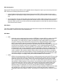
TT5800 Product Photos
TT5800 PCB
IEEE 802.11a miniPCI Card
TT5800 Enclosure (Cast Aluminum, Powder Coated Silver)
4
Product Features
•
•
•
•
•
•
•
•
•
•
•
Compact size for small enterprise or system integrate service market
Compliant with IEEE 802.11a specifications
Supports 64/128-bit WEP, WPA and IEEE802.1x
Supports Atheros Super A (up to 108Mbps)
Intelligent firmware upgrade via Web browser
Built-in Web-based utility for easy configuration from any Web browser
Support POE (IEEE 802.3af) function
Supports wireless bridging and MAC address filtering
Super bright LED indicating status and signal level (RSSI)
Provide 10/100M, auto sensing MDI/MDI-X Ethernet port
EzManager Support
*Atheros Super G (Proprietary technology of Atheros Communication Inc.) would only work in situations where both
ends of the communication link are using the Atheros radio chipset.
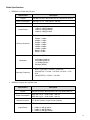
Product Specifications
Main Chips
•
•
CPU: Ubicom IP3023
Radio: Supports 802.11a Atheros AR5213+AR5112
Mechanical
•
Chassis Dimension (W x D x L): 161mm x 30mm x 119mm
Board Specifications
Specification
Description
Network Standard
IEEE 802.11 a, IEEE 802.3, IEEE802.3x
Ethernet
10/100BaseT Ethernet, Auto MDI/MDI-X
Network Architecture
Infrastructure; Ad-Hoc
MAC
CSMA/CA
POWER, Wireless LAN(RF),Ethernet LAN, Receives Signal
Strength(RSS)
Reset to Default Button
Status Indicators
Push Button
5
Radio Specifications
•
IEEE 802.11a 5 GHz mini-PCI card
Specification
Chipset
Description
MAC/BB Processor Atheros AR5213 RF Chip Atheros AR5112
Power Consumption
IEEE 802.11a TX: ~1000 mA RX: ~400 mA
Antenna Connector
N-type Female
Output Power
•
•
•
•
16dBm (± 2dB) @ 54Mbps
17dBm (± 2dB) @ 48Mbps
18dBm (± 2dB) @ 36Mbps
19dBm (± 2dB) @ 6 Mbps
IEEE 802.11a Sensitivity @ 10% Packet Error Rate
Receiver Sensitivity
•
•
•
•
•
•
•
•
54Mbps: -70dBm
48Mbps: -71dBm
36Mbps: -75dBm
24Mbps: -79dBm
18Mbps: -82dBm
12Mbps: -84dBm
9Mbps: -86dBm
6Mbps: -87dBm
IEEE 802.11a (OFDM)
Modulation
Operating Frequency
•
•
•
•
48/54 Mbps (QAM-64)
24/36 Mbps (QAM-16)
12/18 Mbps (QPSK)
6/9 Mbps (BPSK)
•
USA(FCC): 5.15GHz ~ 5.25GHz, 5.25GHz ~ 5.35GHz, 5.47
GHz ~ 5.725 GHz, 5.725 GHz ~ 5.825 GHz
Europe(ETSI): 5.15 GHz ~ 5.35 GHz, 5.47 GHz ~ 5.725
GHz
Japan(TELEC): 5.15 GHz ~ 5.25 GHz
•
•
•
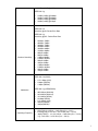
IEEE 802.11b/g 2.4 GHz mini-PCI card
Specification
Chipset
Description
MAC/BB Processor Atheros AR5213 RF Chip Atheros AR5112
Power Consumption
IEEE 802.11b TX: ~1500 mA RX: ~400 mA
IEEE 802.11g TX: ~1500 mA RX: ~400 mA
Antenna Connector
U.Fl R-SMT (Inside), N-type Female (Outside)
IEEE 802.11b:
Output Power
•
•
•
22dBm (± 3dB) @ 1Mbps
22dBm (± 3dB) @ 2Mbps
22dBm (± 3dB) @ 5.5Mbps
6
•
22dBm (± 3dB) @ 11Mbps
IEEE 802.11g:
•
•
•
•
21dBm (±3dB) @ 54Mbps
22dBm (±3dB) @ 48Mbps
22dBm (±3dB) @ 36Mbps
22dBm (±3dB) @ 6 Mbps
IEEE 802.11b
Sensitivity @ 8% Packet Error Rate
IEEE 802.11g
Sensitivity @10% Packet Error Rate
Receiver Sensitivity
•
•
•
•
•
•
•
•
•
•
•
•
•
•
•
•
54Mbps:-72dBm
48Mbps:-73dBm
36Mbps:-77dBm
24Mbps:-81dBm
18Mbps:-84dBm
12Mbps:-86dBm
9Mbps:-88dBm
6Mbps:-89dBm
11Mbps:-88dBm
5.5Mbps:-90dBm
2Mbps:-92dBm
1Mbps:-95dBm
11Mbps:-88dBm
5.5Mbps:-90dBm
2Mbps:-92dBm
1Mbps:-95dBm
IEEE 802.11b (DSSS)
•
•
•
5.5/11 Mbps (CCK)
2 Mbps (DQPSK)
1 Mbps (DBPSK)
IEEE 802.11g (OFDM/DSSS)
Modulation
Operating Frequency
•
•
•
•
•
•
•
48/54 Mbps (QAM-64)
24/36 Mbps (QAM-16)
12/18 Mbps (QPSK)
6/9 Mbps (BPSK)
5.5/11Mbps (CCK)
2Mbps (DQPSK)
1Mbps (DBPSK)
•
•
•
USA(FCC): 2.412GHz ~ 2.462 GHz (CH1 ~ CH11)
Europe(ETSI): 2.412 GHz ~ 2.472 GHz (CH1 ~ CH13)
Japan(TELEC) : 11b: 2.412 GHz ~ 2.484 GHz (CH1 ~ CH14)
11g: 2.412 GHz ~ 2.472 GHz (CH1 ~ CH13)
7
LED Definition
Item
Power
RF(WLAN)
LAN
ON (Red)
Off
Specification
Power on
No power
On (Yellow)
Connected
Off
Not connected
Blinking(Green)
Connected and transmitting
On (Green)
Connected
Off
Not connected
Blinking(Green)
Connected and transmitting
Blinking left to
Received Signal Strength right
Indicator (RSSI)
On
Not connected (Scanning for AP)
Connected, indicating Received Signal
Strength.
Software Specification
Item
Bridge Features
Security Features
Management Features
•
•
•
•
•
•
•
•
•
•
•
Specification
Universal Bridging
MAC Address Cloning
RTS Threshold/Fragmentation Threshold
Infrastructure or Ad-Hoc Mode
Non-IP Traffic Bridging
64-Bit/128-Bit WEP Encryption
WPA Personal Using TKIP or AES
WPA Enterprise Using TKIP or AES
802.1x Authenticator
Cisco LEAP Support
MAC Address Filter
•
•
•
•
•
•
Web Access (Username/Password Protected)
Static IP
Automatic Device Discovery & Configuration
SNMP v1, DHCP and PPPoE (Ethernet or Wireless)
Firmware Upgrade via Web Browser
Transmit Power Adjustment
External AC Power Adapter
Item
Specification
Input Voltage
110-240VAC
Line Frequency
50/60Hz
Power Output to M/B
48VDC, 1A
8
Environmental
Item
Operating Temperature
Storage Temperature
Specification
-20 C to 40 C (-4 F to 104 F),
10 to 90% (non-condensing)
-25 C to 70 C (-13 F to 158 F),
10 to 90% (non-condensing)
Standards / Regulatory Compliance
•
CE, FCC
Product Kit Part Listing
1.
2.
3.
4.
5.
6.
7.
8.
TT5800 802.11a PCBA or TT2400 802.11b/g PCBA (1)
IEEE 802.11a o r IEEE 802.11b/g mini-PCI radio card (1)
Power over Ethernet Injector (1)
48VDC Power Adapter (1)
Ethernet Cable (2)
Waterproof RJ-45 Connector (1)
Mounting Hardware (1)
User Manual
Note: If any item listed above is damaged or missing, please contact your dealer immediately.
System Requirements
•
•
•
•
Any desktop or laptop with an Ethernet interface
TCP/IP protocol suite installed
Standard CAT5 Ethernet cables with RJ45 connectors
Internet Explorer 5.0 or later / Firefox 1.0 or higher
9
Installation
Preparation for Installation
Always double check for any missing parts from the kit you received before deployment.
The next step is to set up the computer Ethernet interface for configuring the TT5800/TT2400. Since the default IP
Address of the unit is on the 192.168.10.x IP range in both Client Bridge and AP mode you will need to set the Ethernet
interface within the same IP range, where x will have to be a free IP address number from 1-254.
Check the following section - “Hardware Installation” and the next chapter - “Configuring Windows for IP Networking” to
obtain complete details.
Hardware Installation
Follow the procedure below to install your TT5800/TT2400 device:
1.
Select a suitable place on the network to install the TT5800/TT2400. For best wireless reception and
performance the external antenna should be positioned within Line of Sight from the AP with proper alignment.
2.
Connect the TT5800/TT2400 to the ODU side of the PoE Injector, via a straight Ethernet cable (Cat-5), and then
connect the NET side of the PoE Injector to either a computer or an Ethernet Switch. Note: The TT5800/TT2400
now fully supports the MDI/MDI-X standard and no longer requires the use of a cross over cable to connect
directly with a computer.
3.
Connect the 48VDC power adapter to the power jack on the PoE injector to power on the TT5800/TT2400.
4.
Check the LEDs on the TT5800/TT2400 to confirm if the status is okay. At this point the Power (PWR) LED
indicator should be red and Ethernet (LAN) LED should be green. The RF light should light up once the unit is
associated wirelessly with another wireless device. However at this point the unit is still in factory default setting
so do not be alarmed that the WLAN light doesn’t light up.
5.
Now the hardware installation is complete and you may proceed to the next chapter –“Configuring Windows for
IP Networking” for instructions on setting up network configurations.
10
Configuring Windows for IP Networking
To establish a communication link between your PC and TT5800/TT2400, you will need to set up a static IP address
for your computer first. This section helps you configure the network settings for your operating system. Please follow
the procedures below to complete the settings:
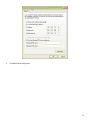
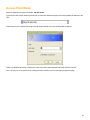
Windows XP
1.
Click Start on the taskbar and from the Control Panel choose Network Connections. Right-click the Local
Area Connection icon and then choose Properties from the menu. You should see the Local Area Connection
Properties dialog box shown below.
2.
Select the Internet Protocol (TCP/IP) for your network card, and then click Properties.
3.
In the opened dialog box, choose Use the following IP address
4.
Under the General tab, choose Use the following IP address, and then specify an IP address. For example,
type in 192.168.10.X in the IP Address (where X is any free IP number from 1-254, excluding 241) area and
255.255.255.0 in the Subnet Mask area.
11
5.
Click OK to finish configuration.
12
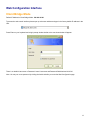
Web Configuration Interface
Client Bridge Mode
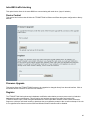
Default IP Address in Client Bridge Mode: 192.168.10.241
To access the web control interface please open up a browser window and type in the factory default IP address in the
URL.
Press Enter on your keyboard and a login prompt window similar to the one shown below will appear.
There is no default User name or Password. Leave User name and Password field blank and click OK.
Note: You may set a new password by clicking the Admin tab after you enter the Web Configuration page.
13
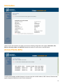
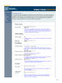
Information
Under the main web interface home page you will see the following configuration menu pages: Information, APs,
Wireless, Security, Admin and Advanced. Detailed information for each section is provided below:
Access Points (APs)
The APs section displays available hotspots in the area along with the MAC address, SSID, Channel, Wireless mode,
signal strength and transmission rate for each access point.
14
Wireless
15
Wireless On/Off
This is the on/off switch of the radio card.
Wireless Mode
Infrastructure: An 802.11 networking framework in which devices communicate with each other by first going through
an Access Point (AP).
Ad-hoc: An 802.11 networking framework in which devices or stations communicate directly with each other, without
the use of an access point (AP). Use this mode if there is no wireless infrastructure or where services are not required.
Wireless Network Name (SSID)
Network Name is also known as SSID, which stands for Service Set Identifier. Any client in Infrastructure mode has to
indicate the SSID of an Access Point to access a service such as internet access through the Access point.
Access Point Identifier (BSSID)
The Basic Service Set Identifier is the unique identifier (MAC address) of an access point in a Basic Service Set (BSS)
network. The subscriber unit is forced to associate with this particular unit if there are multiple access points in the
network.
Transmission rate (Mbits/s)
This option indicates the transmission rate of the bridge. Specify the rate according to the speed of your wireless
network from the list. Most of the time the default setting, Best (automatic), should be selected for best performance.
The setting can be adjusted manually if the link quality and signal strength are unusually low or high to get the best
performance.
802.11 Mode
Wireless mode allows the user to select whether this subscriber unit will connect to an 802.11b only network, an
802.11g only network, an 802.11a only network or both b/g networks. For b or g only wireless devices on the network,
selecting 802.11b or 802.11g only mode will provide better performance than mixed mode. In the case of TT5800 only
802.11a mode is allowed. For TT2400 the options of 802.11b, 802.11g only or Mixed 802.11g and 802.11b are
available.
RF Transmit Power
This section controls the power output for the mini-PCI radio card. The valid input range for this section is in the range
of 0-30 in dBm units or (1mw – 1000mw). The default value is 23 dBm or 200mW.
Super Mode
Super Mode is only supported if both the client and the AP are using compatible Atheros radio chipsets
•
•
•
•
Disabled
Super A/G without Turbo
Super A/G with Static Turbo
Super A/G with Dynamic Turbo (AR enabled)
16
Country and Region
This option selects the country and region of operation. Every device should be configured to use the proper regional
settings which comply with and do NOT violate the radio regulatory laws at the installed location.
Channel
Channels are important to understand because they affect the overall capacity of your Wireless LAN. A channel
represents a narrow band of radio frequency. A radio frequency modulates within a band of frequencies; as a result
there is a limited amount of bandwidth within any given range to carry data. It is important that the frequencies do not
overlap or else the throughput would be significantly reduced as the network sorts and reassembles the data packets
sent over the air.
For the TT2400: 2.4 GHz – 2.497 GHz frequency range, there are only 3 channels out of the 11 available that do not
overlap with one another. To avoid interference within a network with multiple APs, set each AP to use one of the 3
channels (e.g. Channel 1) and then the other AP to be one of the other 2 channels (i.e. Channel 6 or Channel 11)
within the range of the wireless radio. This simple method will reduce interference and improve network reliability.
802.11b/g Wireless Channel Frequency Range: 2.4 GHz – 2.497 GHz
802.11b/g Non-overlapping Channel Frequency Ranges
•
•
•
Channel 1 = 2.401 GHz – 2.423 GHz
Channel 6 = 2.426 GHz – 2.448 GHz
Channel 11 = 2.451 GHz – 2.473 GHz
Americas: Wireless Channels 1 – 11
Asia: Wireless Channels 1 – 14
Europe: Wireless Channels 1 – 13
802.11a Wireless Channel Frequency Range: 5.15 GHz – 5.35 GHz, 5.725 – 5.825
802.11a is an extension to 802.11 that applies to wireless LANs and provides up to 54 Mbps in the 5GHz band.
802.11a uses an orthogonal frequency division multiplexing encoding scheme rather than FHSS or DSSS. Unlike that
of 802.11b/g, 802.11a standard separates its channels into 3-100MHz segments in the US.
The lower and middle band accommodates 8 channels in a total bandwidth of 200 MHz and the upper band
accommodates 4 channels in a 100 MHz bandwidth. The frequency channel center frequencies are spaced 20 MHz
apart. The outermost channels of the lower and middle bands are centered 30 MHz from the outer edges. In the upper
band the outermost channel centers are 20 MHz from the outer edges.
In addition to the frequency and channel allocations, transmit power is a key parameter regulated in the 5 GHz U-NII
band. Three transmit power levels are specified: 40 mW, 200 mW and 800 mW. The upper band defines RF transmit
power levels suitable for bridging applications while the lower band specifies a transmit power level suitable for shortrange indoor home and small office environments.
802.11a Non-overlapping Channel Frequency Ranges
Lower Band (5.15 - 5.25 GHz) – Maximum Output Power 40mW
•
•
•
•
Channel 36 = 5.15 – 5.18
Channel 40 = 5.18 – 5.20
Channel 44 = 5.20 – 5.22
Channel 48 = 5.22 – 5.25
Middle Band (5.25 - 5.35 GHz) – Maximum Output Power 200mW
•
•
•
•
Channel 52 = 5.25 – 5.28
Channel 56 = 5.28 – 5.30
Channel 60 = 5.30 – 5.32
Channel 64 = 5.32 – 5.35
17
Upper Band (5.725 - 5.825 GHz) – Maximum Output Power 800mW
•
•
•
•
•
Channel 149 = 5.725 – 5.745
Channel 153 = 5.745 – 5.765
Channel 157 = 5.765 – 5.785
Channel 161 = 5.785 – 5.805
Channel 165 = 5.805 – 5.825
Special Atheros Turbo Mode Channels
*Use this setting only when both side of the wireless connection is using the Atheros chipset. The radio will combine 2
free channels for the wireless transmission to double the bandwidth.
•
•
•
•
•
Channel 42 = 5.210
Channel 50 = 5.250
Channel 58 = 5.290
Channel 152 = 5.760
Channel 160 = 5.800
18
Security
19
WPA Configuration
Short for Wi-Fi Protected Access, WPA is a Wi-Fi standard that was designed to improve upon the security features of
WEP. WPA has the following improvements over WEP:
•
Improved data encryption through temporal key integrity protocol (TKIP). TKIP scrambles the keys using a
hashing algorithm. By adding an integrity-checking feature, TKIP ensures that keys have not been tampered
with.
•
User authentication through the Extensible Authentication Protocol (EAP). WEP regulates access to a wireless
network based on a computer’s hardware-specific MAC address, which is relatively simple to be sniffed out
and stolen. EAP is built on a more secure public-key encryption system to ensure that only authorized network
users can access the network.
WPA Enable
This option enables the WPA Authenticator. Note that any client that does not support the WPA standard will not be
able to handshake / authenticate with a WPA enabled device.
WPA Mode
•
•
WPA
o
Designed to secure present and future versions of IEEE 802.11 devices, WPA is a subset of the IEEE
802.11i specification. WPA addresses all known vulnerabilities in WEP. WPA also provides user
authentication, since WEP lacks any means of authentication. WPA replaces WEP with a strong new
encryption technology called Temporal Key Integrity Protocol (TKIP) with Message Integrity Check
(MIC). It also provides a scheme of mutual authentication using IEEE 802.1X/Extensible
Authentication Protocol (EAP) authentication or pre-shared key (PSK) technology. WPA was designed
and has been scrutinized by well-known cryptographers. It can be implemented immediately and
inexpensively as a software or firmware upgrade to most existing Wi-Fi CERTIFIED™ access points
and client devices with minimal degradation in network performance. WPA offers standards-based, WiFi CERTIFIED security. It assures users that the Wi-Fi CERTIFIED devices they buy will be crossvendor compatible. When properly installed, WPA provides a high level of assurance to enterprises,
small businesses and home users that data will remain protected and that only authorized users may
access their networks. For enterprises that have already deployed IEEE 802.1X authentication, WPA
offers the advantage of leveraging existing authentication databases and infrastructure.
WPA2
o WPA2 is the second generation of WPA security; providing enterprise and consumer Wi-Fi® users with
a high level of assurance that only authorized users can access their wireless networks. Launched in
September 2004 by the Wi-Fi Alliance, WPA2 is the certified interoperable version of the full IEEE
802.11i specification which was ratified in June 2004. Like WPA, WPA2 supports IEEE 802.1X/EAP
authentication or PSK technology. It also includes a new advanced encryption mechanism using the
Counter-Mode/CBC-MAC Protocol (CCMP) called the Advanced Encryption Standard (AES). AES
satisfies U.S. government security requirements. It has been adopted as an official government
standard by the U.S. Department of Commerce and the National Institute of Standards and
Technology (NIST). Organizations that require the AES encryption available in WPA2 should be aware
that upgrading to it may require new hardware. Section II of this document offers a roadmap for
organizations planning to upgrade to WPA2. Considerations for its deployment are outlined in Section
III.
20
Cipher Type
•
•
•
TKIP
o
AES
o
Temporal Key Integrity Protocol is an upgrade to the WEP known as WEP 1.1 that fixes known
security problems in WEP’s implementation of the RC4 stream cipher. TKIP scrambles the keys using
a hashing algorithm and by adding an integrity-checking feature, ensures that the keys haven’t been
tampered with.
Advanced Encryption Standard (Rijndael Cypher) is the U.S. government's next-generation
cryptography algorithm, which will replace DES and 3DES. AES works at multiple network layers
simultaneously. AES Supports 128, 192 and 256 bit keys. Unlike the older standard, AES and 802.11i
(WEP version 2) are based on 32bit processing.
TKIP and AES
o If clients support both the TKIP and AES standards then this would be the strongest cipher type to use
that combines both TKIP and AES security.
PSK
PSK stands for Pre-Shared-Key and serves as a password. User may key in 8 to 63 characters string to set the
password and activate 802.1x Authentication. Note that the same password must be used at both ends of the
communication link (access point and client end).
WEP Configuration
Short for Wired Equivalent Privacy, a security protocol for wireless local area networks (WLANs) defined in the 802.11b
standard. WEP is designed to provide the same level of security as that of a wired LAN.
Enable WEP
To enable the WEP Authenticator
Default WEP key to use
•
WEP Key 1-4
Select the key to be used as the default key. Data transmissions are always encrypted using the default key. The other
keys can only be used to decrypt received data.
Authentication
•
Open - Open system authentication involves a two-step authentication transaction sequence. The first step in
the sequence is the identity assertion and request for authentication. The second step in the sequence is the
authentication result. If it is “successful”, the station shall be mutually authenticated. Open system
authentication does not provide authentication. It provides identification using the wireless adapter's MAC
address. Open system authentication is used when no authentication is required. It is the default
authentication algorithm.
Open system authentication uses the following process:
1. The authentication-initiating wireless client sends an IEEE 802.11 authentication management frame that contains
its identity.
2. The receiving wireless AP checks the initiating station's identity and sends back an authentication verification
frame.
3. With some wireless APs, you can configure the MAC addresses of allowed wireless clients. However, configuring
21
the MAC address does not provide sufficient security because the MAC address of a wireless client can be
spoofed.
•
Shared Key - Shared key authentication supports authentication of stations as either a member of those who
know a shared secret key or a member of those who do not. Shared key authentication is not secure and is
not recommended for use. It verifies that an authentication-initiating station has knowledge of a shared secret.
This is similar to pre-shared key authentication for Internet Protocol security (IPSec). The 802.11 standard
currently assumes that the shared secret is delivered to the participating wireless clients by means of a more
secure channel that is independent of IEEE 802.11. In practice, a user manually types this secret for the
wireless AP and the wireless client.
Shared key authentication uses the following process:
1. The authentication-initiating wireless client sends a frame consisting of an identity assertion and a request
for authentication.
2. The authenticating wireless node responds to the authentication-initiating wireless node with challenge
text.
3. The authentication-initiating wireless node replies to the authenticating wireless node with the challenge
text that is encrypted using WEP and an encryption key that is derived from the shared key authentication
secret.
4. The authentication result is positive if the authenticating wireless node determines that the decrypted
challenge text matches the challenge text originally sent in the second frame. The authenticating wireless
node sends the authentication result.
5. Because the shared key authentication secret must be manually distributed and typed, this method of
authentication does not scale appropriately in large infrastructure network mode, such as corporate
campuses.
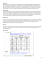
WEP key lengths
64 bit (10 Hex Digit)
WEP Key type
Example
64-bit WEP with 5 characters
Key1= 2e3f4
Key2= 5y7js
Key3= 24fg7
Key4= 98jui
64-bit WEP with 10 hexadecimal digits
('0-9', 'A-F')
Key1= 123456789A
Key2= 23456789AB
Key3= 3456789ABC
Key4= 456789ABCD
128 bit (26 Hex Digit)
WEP Key type
Example
128-bit WEP with 13 characters
Key1= 2e3f4w345ytre
Key2= 5y7jse8r4i038
Key3= 24fg70okx3fr7
Key4= 98jui2wss35u4
128-bit WEP with 26 hexadecimal digits
('0-9', 'A-F')
Key1= 112233445566778899AABBCDEF
Key2= 2233445566778899AABBCCDDEE
Key3= 3344556677889900AABBCCDDFF
Key4= 44556677889900AABBCCDDEEFF
22
Admin
Device Name
This is the name that the bridge will use to identify itself to external configuration and IP address programs. This is not
the same as the SSID. It is okay to leave this blank if you are not using these programs.
SNMP Setting
SNMP enable
Option to enable or disable SNMP support.
23
Community
The SNMP Read-only Community string is like a user id or password that allows access to a router's or other device's
statistics or management information. InterMapper sends the community string along with all SNMP requests. If the
community string is correct, the device responds with the requested information. If the community string is incorrect,
the device simply discards the request and does not respond.
Factory default setting for the read-only community string is set to "public". It is standard practice to change all the
community strings so that outsiders cannot see information about the internal network. (In addition, the administrator
may also employ firewalls to block any SNMP traffic to ports 161 and 162 on the internal network.)
Change this value to have InterMapper use the new string when querying SNMP devices.
IP Settings
IP Address Mode
•
Static
o Manually setup an IP address for this device.
•
DHCP
o Set up the bridge as a DHCP client which will pick up an IP address from a DHCP server.
Default IP address
The default Client Bridge Mode IP address: 192.168.10.241
Default subnet mask
The factory subnet default value is 255.255.255.0
Default gateway
The factory gateway default address is 192.168.10.1
24
Security
This section is used to set up the administrative login name and password.
User name
This is the user name that you must type when logging into the web interface.
Administrator Password
This is the password that you must type when logging into the web interface. You must enter the same
password into both boxes for confirmation.
Syslog
Syslog Enabled
Option to enable or disable Syslog support.
Syslog Daemon Server
The Syslog server IP address input box.
Ping Watchdog Utility
Ping Watchdog Utility Enabled
If enabled, the Ping Watchdog utility tracks the TCP/IP link between this device and another remote destination at the
other end of the wireless link. When the remote destination is unreachable (loss of connection) the Ping Watchdog
Utility will reboot the unit in an attempt to re-establish the connection. When the TT is up for 2 minutes, the ping
watchdog utility will start to ping the remote network device every 20 seconds, if there is no icmp response for 3 times
in a row then the ping watchdog will kick off the reboot action.
Destination IP address of the Ping Watchdog Utility
This is the IP address of the remote destination.
25
Device Control
This section has functions that will allow the TT5800/TT2400 to Reboot and Reset the system configuration to factory
defaults.
Firmware Upgrade
This section allows the TT5800/TT2400 firmware to be upgraded or changed directly from the web interface. Click on
the Browse button to select a file from the host machine.
Register
The TT5800/TT2400 has implemented a hardware modification authorization process to prevent use by fraudulent
hardware from other manufacturers. This will require any hardware change on the radio card used on the
TT5800/TT2400 to input a serial code generated based on each unique MAC address. Please contact Teletronics
Support to a pickup a valid serial number to deactivate the pre-registration protection after a radio card swap. If the unit
is not registered some features such as SSID and Wireless Channel selection will be disabled.
26
Advanced
27
Cloning
Cloning Mode
•
WLAN Card
o
•
If set to "WLAN Card", the MAC Address of the WLAN Card will be used. When multiple Ethernet
devices are connected to the Bridge, the MAC Address of the Bridge will not change.
Ethernet Client
o
If set to "Ethernet Client", the MAC Address from the first Ethernet client that transmits data through
the Bridge will be used. This means the client MAC address will become the alias address to the
Bridge.
Advanced Wireless
Fragmentation threshold
Fragmentation Threshold is the maximum length of the frame beyond which payload must be broken up (fragmented)
into two or more frames. Collisions occur more often for long frames because sending them occupies the channel for a
longer period of time, increasing the chance that another station will transmit and cause collision. Reducing
Fragmentation Threshold results in shorter frames that "busy" the channel for shorter periods, reducing packet error
rate and resulting retransmissions. However, shorter frames also increase overhead, degrading maximum possible
throughput, so adjusting this parameter means striking a good balance between error rate and throughput.
RTS threshold
RTS Threshold is the frame size above which an RTS/CTS handshake will be performed before attempting to transmit.
RTS/CTS asks for permission to transmit to reduce collisions but adds considerable overhead. Disabling RTS/CTS can
reduce overhead and latency in WLANs where all stations are close together but can increase collisions and degrade
performance in WLANs where stations are far apart and unable to sense each other to avoid collisions (aka Hidden
Nodes). If you are experiencing excessive collisions you can try turning RTS/CTS on or (if already on) reduce
RTS/CTS Threshold on the affected stations.
Burst time
Maximum burst time is a feature based on the PRISM Nitro; a new WLAN software solution that more than triples
802.11g throughput in a mixed-mode environment and offers up to 50 percent greater throughput performance in
802.11g-only networks. PRISM Nitro is fully IEEE 802.11 compliant and uses prioritization algorithms and enhanced
protection mechanisms to significantly increase wireless networking performance.
The recommended value for the maximum burst time for 11b or the mixed 11b/g environment is 650. The 11g only
mode uses the value 1400.
Beacon Period
In wireless networking, a beacon is a packet sent by a connected device to inform other devices of its presence and
readiness. When a wirelessly networked device sends a beacon, it includes with it a beacon interval which specifies
the period of time before it will send the beacon again. The interval tells receiving devices on the network how long
they can wait in low-power mode before waking up to handle the beacon. Network managers can adjust the beacon
interval, usually measured in milliseconds (ms) or its equivalent, kilo microseconds (Kμsec).
28
802.11d
802.11d is a wireless network communications specification for use in countries where systems using other standards
in the 802.11 family are not allowed to operate. The 802.11d specification is well suited for systems that want to
provide global Roaming.
ACK Timeout
When a packet is sent out from 802.11 Station A it will wait for an 'ACKnowledgement frame' from 802.11 Station B.
Station A will only wait for a certain amount of time (ACK timeout) or ACK window. If the ACK is NOT received within
that timeout period then the packet will be re-transmitted from Station A resulting in reduced throughput. When sending
LOTS of packets as in 802.11g and 802.11a the constant re-transmission could cost severe performance degradation
due to the ACK frame not making it back to 802.11 Station A in time. This will have a dramatic impact on the throughput
of the link regardless of the quantity of signal strength and good receiver sensitivity.
Antenna Selection
* Please refer to Appendix G on page 59 for further information.
29
Access Point Mode
Default IP Address in Access Point Mode: 192.168.10.240
To access the web control interface please open up a browser window and type in the factory default IP address in the
URL.
Press Enter on your keyboard and a login prompt window similar to the one shown below will appear.
There is no default User name or Password. Leave User Name and Password field blank and then click OK.
Note: You may set a new password by clicking the Admin tab after you enter the Web Configuration page
30
Information
Under the main web interface home page you will see the following configuration menu pages:
Information, Stations, Wireless, WDS, Security, Access, Admin, Advanced. Detailed information on each section
is provided below.
Stations
The Stations section will display all the associated clients along with the MAC address and basic RF related
information on the Mode, Rate, Signal and StationIdleTime for each associated client.
31
Wireless
32
Wireless On/Off
Enable or disable the wireless port.
Wireless Network Name (SSID)
Network Name is also known as SSID, which stands for Service Set Identifier. This is where you’re going to setup the
Service Set Identifier name for this AP. Remember that the SSID is cap sensitive just like the password.
Visibility Status
This controls the SSID broadcasting function. If enabled, the SSID will be broadcasted to all wireless clients in the
area. If disabled, wireless clients will not be able to pickup the SSID but must explicitly know the SSID of the unit in
order to associate. The recommended practice is to set the visibility status to invisible after setting up the wireless
network.
Transmission rate (Mbits/s)
This option indicates the transmission rate of the bridge. Specify the rate according to the speed of your wireless
network from the list. Most of the time the default setting, Best (automatic), should be selected for best performance.
The setting can be adjusted manually if the link quality and signal strength are unusually low or high to get the best
performance.
802.11 Mode
Wireless mode allows the user to select whether this Access Point will connect to an 802.11b only network, an 802.11g
only network, an 802.11a only network or both b/g networks. For b or g only wireless devices on the network, selecting
802.11b or 802.11g only mode will provide better performance than mixed mode. In the case of TT5800 only 802.11a
mode is allowed. For TT2400 the options of 802.11b, 802.11g only or Mixed 802.11g and 802.11b are available.
Adaptive Radio Selection
When using dynamic turbo mode with a compatible Atheros radio chipset, this option allows the Access point to switch
to non-turbo mode when non-turbo traffic is detected and vice versa.
Super Mode
Super Mode is only supported if both the client and the AP are using compatible Atheros radio chipsets.
•
•
•
•
Disabled
Super A/G without Turbo
Super A/G with Static Turbo
Super A/G with Dynamic Turbo (AR enabled)
Auto Channel Select
Check this box to enable the Access Point to automatically select the best channel at start up. This may take up to 20
seconds and during this period no clients will be able to associate.
RF Transmit Power
This section controls the power output for the mini-PCI radio card. The valid input range for this section is in the range
of 0-30 in dBm units. The default value is 23 dBm or 200mW.
33
Channel
Channels are important to understand because they affect the overall capacity of your Wireless LAN. A channel
represents a narrow band of radio frequency. A radio frequency modulates within a band of frequencies; as a result
there is a limited amount of bandwidth within any given range to carry data. It is important that the frequencies do not
overlap or else the throughput would be significantly reduced as the network sorts and reassembles the data packets
sent over the air.
For the TT2400: 2.4 GHz – 2.497 GHz frequency range, there are only 3 channels out of the 11 available that do not
overlap with one another. To avoid interference within a network with multiple APs, set each AP to use one of the 3
channels (e.g. Channel 1) and then the other AP to be one of the other 2 channels (i.e. Channel 6 or Channel 11)
within the range of the wireless radio. This simple method will reduce interference and improve network reliability.
802.11b/g Wireless Channel Frequency Range: 2.4 GHz – 2.497 GHz
802.11b/g Non-overlapping Channel Frequency Ranges
•
•
•
Channel 1 = 2.401 GHz – 2.423 GHz
Channel 6 = 2.426 GHz – 2.448 GHz
Channel 11 = 2.451 GHz – 2.473 GHz
Americas: Wireless Channels 1 – 11
Asia: Wireless Channels 1 – 14
Europe: Wireless Channels 1 – 13
802.11a Wireless Channel Frequency Range: 5.15 GHz – 5.35 GHz, 5.725 – 5.825
802.11a is an extension to 802.11 that applies to wireless LANs and provides up to 54 Mbps in the 5GHz band.
802.11a uses an orthogonal frequency division multiplexing encoding scheme rather than FHSS or DSSS. Unlike that
of 802.11b/g, 802.11a standard separates its channels into 3-100MHz segments in the US.
The lower and middle band accommodates 8 channels in a total bandwidth of 200 MHz and the upper band
accommodates 4 channels in a 100 MHz bandwidth. The frequency channel center frequencies are spaced 20 MHz
apart. The outermost channels of the lower and middle bands are centered 30 MHz from the outer edges. In the upper
band the outermost channel centers are 20 MHz from the outer edges.
In addition to the frequency and channel allocations, transmit power is a key parameter regulated in the 5 GHz U-NII
band. Three transmit power levels are specified: 40 mW, 200 mW and 800 mW. The upper band defines RF transmit
power levels suitable for bridging applications while the lower band specifies a transmit power level suitable for shortrange indoor home and small office environments.
802.11a Non-overlapping Channel Frequency Ranges
Lower Band (5.15 - 5.25 GHz) – Maximum Output Power 40mW
•
•
•
•
Channel 36 = 5.15 – 5.18
Channel 40 = 5.18 – 5.20
Channel 44 = 5.20 – 5.22
Channel 48 = 5.22 – 5.25
Middle Band (5.25 - 5.35 GHz) – Maximum Output Power 200mW
•
•
•
•
Channel 52 = 5.25 – 5.28
Channel 56 = 5.28 – 5.30
Channel 60 = 5.30 – 5.32
Channel 64 = 5.32 – 5.35
Upper Band (5.725 - 5.825 GHz) – Maximum Output Power 800mW
•
Channel 149 = 5.725 – 5.745
34
•
•
•
•
Channel 153 = 5.745 – 5.765
Channel 157 = 5.765 – 5.785
Channel 161 = 5.785 – 5.805
Channel 165 = 5.805 – 5.825
Special Atheros Turbo Mode Channels
*Use this setting only when both side of the wireless connection is using the Atheros chipset. The radio will combine 2
free channels for the wireless transmission to double the bandwidth.
•
•
•
•
•
Channel 42 = 5.210
Channel 50 = 5.250
Channel 58 = 5.290
Channel 152 = 5.760
Channel 160 = 5.800
35
WDS (Wireless Distribution System)
Enable WDS
The Wireless Distribution System (Repeater) functionality enables this AP to support wireless traffic to other WDS relay
Access Points. In other words it is like bridging between the 2 access points in order to extend the reach of the
wireless network beyond that of a single AP. By enabling the WDS feature the coverage area of the wireless network is
thus extended for authenticated client devices that can roam from this Access Point to another. WDS can extend the
reach of your network into areas where cabling might be difficult. The TT5800/TT2400 in Access Point mode can
support up to 6 other Access Points for WDS communication.
Enter the MAC Address of other Access Points in the area that you want to add to the WDS. The MAC Address of this
Access Point should be also be added to other access points in the same WDS network to enable intra-AP
communication.
* Please Consult Appendix E on page 55 for further information.
36
Security
37
WPA Configuration
Short for Wi-Fi Protected Access, WPA is a Wi-Fi standard that was designed to improve upon the security features of
WEP. WPA has the following improvements over WEP:
•
Improved data encryption through temporal key integrity protocol (TKIP). TKIP scrambles the keys using a
hashing algorithm. By adding an integrity-checking feature, TKIP ensures that keys have not been tampered
with.
•
User authentication through the Extensible Authentication Protocol (EAP). WEP regulates access to a wireless
network based on a computer’s hardware-specific MAC address, which is relatively simple to be sniffed out
and stolen. EAP is built on a more secure public-key encryption system to ensure that only authorized network
users can access the network.
WPA Enable
This option enables the WPA Authenticator. Note that any client that does not support the WPA standard will not be
able to handshake / authenticate with a WPA enabled device.
WPA Mode
•
•
WPA
o
Designed to secure present and future versions of IEEE 802.11 devices, WPA is a subset of the IEEE
802.11i specification. WPA addresses all known vulnerabilities in WEP. WPA also provides user
authentication, since WEP lacks any means of authentication. WPA replaces WEP with a strong new
encryption technology called Temporal Key Integrity Protocol (TKIP) with Message Integrity Check
(MIC). It also provides a scheme of mutual authentication using IEEE 802.1X/Extensible
Authentication Protocol (EAP) authentication or pre-shared key (PSK) technology. WPA was designed
and has been scrutinized by well-known cryptographers. It can be implemented immediately and
inexpensively as a software or firmware upgrade to most existing Wi-Fi CERTIFIED™ access points
and client devices with minimal degradation in network performance. WPA offers standards-based, WiFi CERTIFIED security. It assures users that the Wi-Fi CERTIFIED devices they buy will be crossvendor compatible. When properly installed, WPA provides a high level of assurance to enterprises,
small businesses and home users that data will remain protected and that only authorized users may
access their networks. For enterprises that have already deployed IEEE 802.1X authentication, WPA
offers the advantage of leveraging existing authentication databases and infrastructure.
WPA2
o WPA2 is the second generation of WPA security; providing enterprise and consumer Wi-Fi® users with
a high level of assurance that only authorized users can access their wireless networks. Launched in
September 2004 by the Wi-Fi Alliance, WPA2 is the certified interoperable version of the full IEEE
802.11i specification which was ratified in June 2004. Like WPA, WPA2 supports IEEE 802.1X/EAP
authentication or PSK technology. It also includes a new advanced encryption mechanism using the
Counter-Mode/CBC-MAC Protocol (CCMP) called the Advanced Encryption Standard (AES). AES
satisfies U.S. government security requirements. It has been adopted as an official government
standard by the U.S. Department of Commerce and the National Institute of Standards and
Technology (NIST). Organizations that require the AES encryption available in WPA2 should be aware
that upgrading to it may require new hardware. Section II of this document offers a roadmap for
organizations planning to upgrade to WPA2. Considerations for its deployment are outlined in Section
III.
38
Cipher Type
•
•
•
TKIP
o
AES
o
Temporal Key Integrity Protocol is an upgrade to the WEP known as WEP 1.1 that fixes known
security problems in WEP’s implementation of the RC4 stream cipher. TKIP scrambles the keys using
a hashing algorithm and by adding an integrity-checking feature, ensures that the keys haven’t been
tampered with.
Advanced Encryption Standard (Rijndael Cypher) is the U.S. government's next-generation
cryptography algorithm, which will replace DES and 3DES. AES works at multiple network layers
simultaneously. AES Supports 128, 192 and 256 bit keys. Unlike the older standard, AES and 802.11i
(WEP version 2) are based on 32bit processing.
TKIP and AES
o If clients support both the TKIP and AES standards then this would be the strongest cipher type to use
that combines both TKIP and AES security.
PSK
PSK stands for Pre-Shared-Key and serves as a password. User may key in 8 to 63 characters string to set the
password and activate 802.1x Authentication. Note that the same password must be used at both ends of the
communication link (access point and client end).
WPA Group Key Update Interval
The Group Key (Group Transient Key) is a shared key among all Supplicants connected to the same AP, and is used to
secure multicast/broadcast traffic. It is not used for normal unicast traffic. A pair wise Transient Key secures the unicast
traffic. Group Key renewal controls how often the Group Transient Key is changed. The Group Key renewal does not
control the update period for the pair wise Transient Key. The pair wise Transient Key is changed each time the
Supplicant authenticates or re-authenticates.
802.1X Configuration
Remote RADIUS server configuration settings. There are two sections to setup 2 RADIUS servers for the
TT5800/TT2400 to connect to. At any given time the TT5800/TT2400 will connect to one RADIUS server for
authentication and will use the other one as a backup if that option is configured.
802.1X enabled
Option that enables or disables remote RADIUS authentication.
Authentication timeout (mins)
The default value is 60(minutes). When the time expires, the device will re-authenticate with RADIUS server.
RADIUS server IP address
Enter the RADIUS server IP address.
RADIUS server port number
Port used for RADIUS, the port number must be the same as the RADIUS server‘s, normally the port is 1812.
39
RADIUS server shared secret
When registered with a RADIUS server, a password will be assigned. This would be the RADIUS server shared secret.
MAC Address Authentication
Use client MAC address for authentication with RAIDUS server.
WEP Configuration
Short for Wired Equivalent Privacy, a security protocol for wireless local area networks (WLANs) defined in the 802.11b
standard. WEP is designed to provide the same level of security as that of a wired LAN.
Enable WEP
To enable the WEP Authenticator
Default WEP key to use
•
WEP Key 1-4
Select the key to be used as the default key. Data transmissions are always encrypted using the default key. The other
keys can only be used to decrypt received data.
Authentication
•
Open - Open system authentication involves a two-step authentication transaction sequence. The first step in
the sequence is the identity assertion and request for authentication. The second step in the sequence is the
authentication result. If it is “successful”, the station shall be mutually authenticated. Open system
authentication does not provide authentication. It provides identification using the wireless adapter's MAC
address. Open system authentication is used when no authentication is required. It is the default
authentication algorithm.
Open system authentication uses the following process:
1. The authentication-initiating wireless client sends an IEEE 802.11 authentication management frame that contains
its identity.
2. The receiving wireless AP checks the initiating station's identity and sends back an authentication verification
frame.
3. With some wireless APs, you can configure the MAC addresses of allowed wireless clients. However, configuring
the MAC address does not provide sufficient security because the MAC address of a wireless client can be
spoofed.
•
Shared Key - Shared key authentication supports authentication of stations as either a member of those who
know a shared secret key or a member of those who do not. Shared key authentication is not secure and is
not recommended for use. It verifies that an authentication-initiating station has knowledge of a shared secret.
This is similar to pre-shared key authentication for Internet Protocol security (IPSec). The 802.11 standard
currently assumes that the shared secret is delivered to the participating wireless clients by means of a more
secure channel that is independent of IEEE 802.11. In practice, a user manually types this secret for the
wireless AP and the wireless client.
40
Shared key authentication uses the following process:
6. The authentication-initiating wireless client sends a frame consisting of an identity assertion and a request
for authentication.
7. The authenticating wireless node responds to the authentication-initiating wireless node with challenge
text.
8. The authentication-initiating wireless node replies to the authenticating wireless node with the challenge
text that is encrypted using WEP and an encryption key that is derived from the shared key authentication
secret.
9. The authentication result is positive if the authenticating wireless node determines that the decrypted
challenge text matches the challenge text originally sent in the second frame. The authenticating wireless
node sends the authentication result.
10. Because the shared key authentication secret must be manually distributed and typed, this method of
authentication does not scale appropriately in large infrastructure network mode, such as corporate
campuses.
WEP key lengths
64 bit (10 Hex Digit)
WEP Key type
Example
64-bit WEP with 5 characters
Key1= 2e3f4
Key2= 5y7js
Key3= 24fg7
Key4= 98jui
64-bit WEP with 10 hexadecimal digits
('0-9', 'A-F')
Key1= 123456789A
Key2= 23456789AB
Key3= 3456789ABC
Key4= 456789ABCD
128 bit (26 Hex Digit)
WEP Key type
Example
128-bit WEP with 13 characters
Key1= 2e3f4w345ytre
Key2= 5y7jse8r4i038
Key3= 24fg70okx3fr7
Key4= 98jui2wss35u4
128-bit WEP with 26 hexadecimal digits
('0-9', 'A-F')
Key1= 112233445566778899AABBCDEF
Key2= 2233445566778899AABBCCDDEE
Key3= 3344556677889900AABBCCDDFF
Key4= 44556677889900AABBCCDDEEFF
41
Access
Access Control
Enable access control
If enabled, this feature allows you to associate up to 64 different units/devices by MAC addresses. Any MAC
addresses not programmed into the list will be prohibited from associating with this unit.
42
Admin
43
Device Name
Device Name
This is the name that the Access Point will use to identify itself to external configuration and IP address programs. This
is not the same as the SSID. It is okay to leave this blank if you are not using these programs.
SNMP Setting
SNMP enabled
Option to enable or disable SNMP support
Community
The SNMP Read-only Community string is like a user id or password that allows access to a router's or other device's
statistics. InterMapper sends the community string along with all SNMP requests. If the community string is correct, the
device responds with the requested information. If the community string is incorrect, the device simply discards the
request and does not respond.
Factory default setting for the read-only community string is set to "public". It is standard practice to change all the
community strings so that outsiders cannot access/read information about the internal network. (In addition, the
administrator may also employ firewalls to block any SNMP traffic to ports 161 and 162 on the internal network.)
Change this value to have InterMapper use the new string when querying SNMP devices.
IP Settings
IP Address Mode
•
Static
o Manually setup a static IP address for this device.
•
DHCP
o Set up the access point as a DHCP client which will pick up an IP from a DHCP server.
Default IP address
The default Access Point Mode IP address: 192.168.10.240
Default subnet mask
The factory subnet default value is 255.255.255.0
Default gateway
The factory gateway default address is 192.168.10.1
Security
This section is used to set up the administrative login name and password.
User name
This is the user name that you must type when logging into the web interface.
44
Administrator Password
This is the password that you must type when logging into the web interface. You must enter the same password into
both boxes for confirmation.
Syslog
Syslog Enabled
Option to enable or disable Syslog support.
Syslog Daemon Server
The Syslog server IP address input box.
Ping Watchdog Utility
Ping Watchdog Utility Enabled
If enabled, the Ping Watchdog utility tracks the TCP/IP link between this device and another remote destination at the
other end of the wireless link. When the remote destination is unreachable (loss of connection) the Ping Watchdog
Utility will reboot the unit in an attempt to re-establish the connection.
Destination IP address of the Ping Watchdog Utility
This is the IP address of the remote destination.
45
Intra-BSS traffic blocking
This option blocks clients in the same BSS from communicating with each other. (Layer 2 Isolation)
Device Control
This section has functions that will allow the TT5800/TT2400 to Reboot and Reset the system configuration to factory
defaults.
Firmware Upgrade
This section allows the TT5800/TT2400 firmware to be upgraded or changed directly from the web interface. Click on
the Browse button to select a file from the host machine.
Register
The TT5800/TT2400 has implemented a hardware modification authorization process to prevent use by fraudulent
hardware from other manufacturers. This will require any hardware change on the radio card used on the
TT5800/TT2400 to input a serial code generated based on each unique MAC address. Please contact Teletronics
Support to a pickup a valid serial number to deactivate the pre-registration protection after a radio card swap. If the unit
is not registered some features such as SSID and Wireless Channel selection will be disabled.
46
Advanced
Advanced Wireless
Fragmentation threshold
Fragmentation Threshold is the maximum length of the frame beyond which payload must be broken up (fragmented)
into two or more frames. Collisions occur more often for long frames because sending them occupies the channel for a
longer period of time, increasing the chance that another station will transmit and cause collision. Reducing
Fragmentation Threshold results in shorter frames that "busy" the channel for shorter periods, reducing packet error
rate and resulting retransmissions. However, shorter frames also increase overhead, degrading maximum possible
throughput, so adjusting this parameter means striking a good balance between error rate and throughput.
RTS threshold
RTS Threshold is the frame size above which an RTS/CTS handshake will be performed before attempting to transmit.
RTS/CTS asks for permission to transmit to reduce collisions but adds considerable overhead. Disabling RTS/CTS can
reduce overhead and latency in WLANs where all stations are close together but can increase collisions and degrade
performance in WLANs where stations are far apart and unable to sense each other to avoid collisions (aka Hidden
Nodes). If you are experiencing excessive collisions you can try turning RTS/CTS on or (if already on) reduce
RTS/CTS Threshold on the affected stations.
47
Burst time
Maximum burst time is a feature based on the PRISM Nitro; a new WLAN software solution that more than triples
802.11g throughput in a mixed-mode environment and offers up to 50 percent greater throughput performance in
802.11g-only networks. PRISM Nitro is fully IEEE 802.11 compliant and uses prioritization algorithms and enhanced
protection mechanisms to significantly increase wireless networking performance.The recommended value for the
maximum burst time for 11b or the mixed 11b/g environment is 650. The 11g only mode uses the value 1400.
Beacon Period
In wireless networking, a beacon is a packet sent by a connected device to inform other devices of its presence and
readiness. When a wirelessly networked device sends a beacon, it includes with it a beacon interval which specifies
the period of time before it will send the beacon again. The interval tells receiving devices on the network how long
they can wait in low-power mode before waking up to handle the beacon. Network managers can adjust the beacon
interval, usually measured in milliseconds (ms) or its equivalent, kilo microseconds (Kμsec).
DTIM interval
A Delivery Traffic Indication Message (DTIM) is a signal sent as part of a beacon by an access point to a client device
in sleep mode, alerting the device to a packet awaiting delivery. A DTIM interval, also known as a Data Beacon Rate, is
the frequency at which an access point's beacon will include a DTIM. This frequency is usually measured in
milliseconds (ms) or its equivalent, kilo microseconds (Kμsec).
802.11d
802.11d is a wireless network communications specification for use in countries where systems using other standards
in the 802.11 family are not allowed to operate. The 802.11d specification is well suited for systems that want to
provide global roaming.
ACK Timeout
48
When a packet is sent out from 802.11 Station A it will then wait for an 'ACKnowledgement frame' from 802.11 Station
B. Station A will only wait for a certain amount of time (ACK timeout) or ACK window. If the ACK is NOT received within
that timeout period then the packet will be re-transmitted from Station A resulting in reduced throughput. When sending
lots of packets as in 802.11g and 802.11a the constant re-transmission could cost severe performance degradation
due to the ACK frame not making it back to 802.11 Station A in time. This will have a dramatic impact on the throughput
of the link regardless of signal strength or good receiver sensitivity.
Antenna Selection
* Please refer to Appendix G on page 60 for further information.
49
Appendix A: Warranty Policy
Limited Warranty
All Teletronics’ products are warranted to the original purchaser to be free from defects in materials and workmanship
under normal installation, use, and service for a period of one (1) year from the date of purchase.
Under this warranty, Teletronics International Inc. shall repair or replace (at its discretion) during the warranty period,
any part that proves to be defective in material of workmanship under normal installation, use and service, provided the
product is returned to Teletronics International Inc. or to one of its distributors with transportation charges prepaid.
Returned products must include a copy of the purchase receipt. In the absence of a purchase receipt, the warranty
period shall be one (1) year from the date of manufacture.
This warranty shall be voided if the product is damaged as a result of defacement, misuse, abuse, neglect, accident,
destruction or alteration of the serial number, improper electrical voltages or currents, repair, alteration or maintenance
by any person or party other than a Teletronics International, Inc. employee or authorized service facility, or any use in
violation of instructions furnished by Teletronics International, Inc.
This warranty is also rendered invalid if this product is removed from the country in which it was purchased, if it is used
in a country in which it is not registered for use, or if it is used in a country for which it was not designed. Due to
variations in communications laws, this product may be illegal for use in some countries. Teletronics International, Inc.
assumes no responsibility for damages or penalties incurred resulting from the use of this product in a manner or
location other than that for which it is intended.
IN NO EVENT SHALL TELETRONICS INTERNATIONAL, INC. BE LIABLE FOR ANY SPECIAL, INCIDENTAL OR
CONSEQUENTIAL DAMAGES FOR BREACH OF THIS OR ANY OTHER WARRANTY, EXPRESSED OR IMPLIED,
WHATSOEVER.
Some states do not allow the exclusion or limitation of special, incidental or consequential damages, so the above
exclusion or limitation may not apply to you.
This warranty gives you specific legal rights, and you may also have other rights that vary from state to state.
50
Appendix B: RMA Policy
Product Return Policy
It is important to us that all Teletronics’ products are bought with full confidence. If you are not 100% satisfied with any
product purchased from Teletronics you may receive a prompt replacement or refund subject to the terms and
conditions outlined below.
IMPORTANT: Before returning any item for credit or under warranty repair, you must obtain a Return Merchandise
Authorization (RMA) number by filling out the RMA form. Products will not be accepted without an RMA number. All
products being shipped to Teletronics for repair / refund / exchange must be freight prepaid (customer pays for
shipping). For all under warranty repair/replacement, Teletronics standard warranty applies.
30-Day full refund or credit policy:
1. Product was purchased from Teletronics no more than 30 day prior to the return request.
2. All shipping charges associated with returned items are non-refundable.
3. Products are returned in their original condition along with any associated packaging, accessories, mounting
hardware and manuals. Any discrepancy could result in a delay or partial forfeiture of your credit.
Unfortunately Teletronics cannot issue credits for:
1. Products not purchased from Teletronics directly. If you purchased from a reseller or distributor you must contact
them directly for return instructions.
2. Damaged items as a result of misuse, neglect or improper environmental conditions.
3. Products purchased directly from Teletronics more than 30 days prior to a product return request.
To return any product under 1 year warranty for repair/replacement, follow the RMA procedure.
51
Appendix C: Regulatory Information
Statement of Conditions
We may make improvements or changes in the product described in this documentation at any time. The information
regarding the product in this manual are subject to change without notice.
We assume no responsibility for errors contained herein or for direct, indirect, special, incidental, or consequential
damages with the furnishing, performance or use of this manual or equipment supplied with it, even if the suppliers
have been advised of the possibility of such damages.
Electronic Emission Notices
This device complies with Part 15 of the FCC Rules. Operation is subject to the following two conditions:
(1) This device may not cause harmful interference.
(2) This device must accept any interference received, including interference that may cause undesired operation.
FCC Information
The Federal Communication Commission Radio Frequency Interference Statement includes the following paragraph:
The equipment has been tested and found to comply with the limits for a Class B Digital Device, pursuant to part 15 of
the FCC Rules. These limits are designed to provide reasonable protection against harmful interference in a residential
installation. This equipment generates, uses and can radiate radio frequency energy and if not installed and used in
accordance with instructions, may cause harmful interference to radio communication. However, there is no guarantee
that interference will not occur in a particular installation. If this equipment does cause harmful interference to radio or
television reception, which can be determined by turning the equipment off and on, the user is encouraged to try to
overcome the interference by one or more of the following measures:
-
Reorient or relocate the receiving antenna.
Increase the separation between the equipment and receiver.
Connect the equipment into an outlet on a circuit different from that to which the receiver is connected.
Consult the dealer or an experienced radio/TV technician for help.
The equipment is for home or office use.
Important Note
FCC RF Radiation Exposure Statement: This equipment complies with FCC RF radiation exposure limits set forth for
an uncontrolled environment. This equipment should be installed and operated with a minimum distance of 20cm
between the antenna and your body and must not be co-located or operated in conjunction with any other antenna or
transmitter.
Caution: Changes or modifications not expressly approved by the party responsible for compliance could void the
user's authority to operate the equipment.
R&TTE Compliance Statement
This equipment complies with all the requirements of the Directive 1999/5/EC of the European Parliament and the
Council of 9 March 1999 on radio equipment and telecommunication terminal equipment (R&TTE)and the mutual
recognition of their conformity. The R&TTE Directive repeals and replaces in the directive 98/13/EEC. As of April 8,
2000.
European Union CE Marking and Compliance Notices
Products intended for sale within the European Union are marked, which indicates compliance with the applicable
directives identified below. This equipment also carries the Class 2 identifier.
52
With the Conformité Européene (CE) and European standards and amendments, we declare that the equipment
described in this document is in conformance with the essential requirements of the European Council Directives,
standards and other normative documents listed below:
73/23/EEC Safety of the User (article 3.1.a)
89/336/EEC Electromagnetic Compatibility (article 3.1.b)
1999/5/EC (R&TTE) Radio and Telecommunications Terminal Equipment Directive.
EN 60950 2000 Safety of Information Technology Equipment, Including Electrical Business Equipment.
EN 300 328 V1.4.1(2003) Electromagnetic compatibility and Radio spectrum Matters (ERM); Wideband Transmission
systems;Data transmission equipment operating in the 2,4 GHz ISM band and using spread spectrum modulation
techniques;Harmonized EN covering essential requirements under article 3.2 of the R&TTE Directive.
EN 301 489-1, V1.4.1(2002); EN 301 489-17, V1.2.1(2002) – Electromagnetic compatibility and radio spectrum
matters (ERM); electromagnetic compatibility (EMC) standard for radio equipment and services: Part 1: Common
technical requirements; Part 17: Part 17: Specific conditions for 2,4 GHz wideband transmission systems and5 GHz
high performance RLAN equipment
Warning: According to ERC/REC 70-30 appendix 3 National Restrictions, annex 3 Band A “RLANs and HIPERLANs.”
See list of 802.11b/g restrictions for specific countries under the heading “European Economic Area Restrictions” as
below.
English
This product follows the provisions of the European Directive 1999/5/EC.
Danish
Dette produkt er i overensstemmelse med det europæiske direktiv 1999/5/EF
Dutch
Dit product is in navolging van de bepalingen van Europees Directief 1999/5/EC.
Finnish
Tämä tuote noudattaa EU-direktiivin 1999/5/EY määräyksiä.
French
Ce produit est conforme aux exigences de la Directive Européenne 1999/5/CE.
53
Appendix D: Contact Information
Need to contact Teletronics?
Visit us online for information on the latest products and updates to your existing products at:
http://www.teletronics.com
Can't find information about a product you want to buy on the web? Do you want to know more about networking with
Teletronics products?
Give us a call at: 301-309-8500 or fax your request to: 301-309-8551
For technical support issues you can e-mail us at: [email protected]
If any Teletronics product proves defective during its warranty period, you can email the Teletronics Return
Merchandise Authorization department to obtain a Return Authorization Number at: [email protected]
(Details on Warranty and RMA issues can be found in Appendix A and B)
54
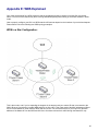
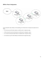
Appendix E: WDS Explained
One of the requirements for a WDS network is that the operational frequency channel on all the APs must be the
same. This is one of the reasons why there is a huge bandwidth penalty when setting up a wireless network in WDS
mode.
How to properly configure your APs in a WDS network will foremost depend on the locations of your wireless hotspots.
Please take a look at the following two WDS topology examples:
WDS in a Star Configuration:
This is the mode to use if you’re expanding the hotspots in the area around your master AP that is connected to the
WAN. What you’ll need to do is enable WDS and ACL on all the APs. Then input each of the MAC addresses of Slave
A,B,C into the Master AP under both the WDS and ACL section. For the Slave APs A,B,C you’ll input only the MAC
address of the Master AP into the WDS and ACL list to limit them to direct their traffic through the Master AP only.
55
WDS in Chain Configuration:
In this configuration setup example you’ll be expanding your wireless network coverage that will span an area in
length.
•
AP A will have only AP B’s MAC address in its WDS and ACL configuration setting.
•
AP B will have AP A and C’s MAC address in its WDS and ACL configuration setting.
•
AP C will have AP B and D’s MAC address in its WDS and ACL configuration setting.
•
AP D will have only AP C’s MAC address in its WDS and ACL configuration setting.
56
Appendix F: TT2400/TT5800 Upgrade FAQ
How to upgrade?
The TT2400/TT5800 could be upgraded either through the web interface or from EZ-Manager. Please check Web
Configuration Interface and Installation sections of this manual for detailed instructions.
Do I need an Activation Key after flashing with a newer firmware, 3.7.x or higher?
No. All the TT2400/TT5800 units shipped from Teletronics are already activated. Since Firmware 3.1.7X and 3.7.X or
higher, Teletronics has now removed the necessary step to provide an activation key to change from SU to AP and vice
versa in our TT2400 and TT5800 product line. For example, if you have a TT2400 in SU mode with 3.6.0 firmware, the
activation key is not required if you upgrade to either 3.7.0 (SU mode) or 3.7.1 (AP mode), or later.
Do I need an Activation Key after flashing with an older firmware, 3.6.x or lower?
You might need an activation key for older firmware. Please check the upgrade guide released with the older firmware.
Do I need an Activation Key after swapping out with another radio card?
Yes, if the radio card is swapped out with another card an activation key will still be required. This rule will apply to all
radio cards swapped out with a different MAC address from the original card.
Which firmware to upgrade?
Currently there are two PCB Hardware revisions V3.0 and V5.0.0, both have 4MB Flash on the board. However the old
firmware 3.1.x released for our first batch back in year 2005 utilized 2MB flash only, while the firmware 3.2.x (or above)
utilized the whole 4MB flash.
The firmware revision 3.1.X and 3.2.X (or above) are not interchangeable due to the different flash size utilization. If
you received boards by default with firmware 3.1.X then you have the 2M version. If you received boards by default
with firmware 3.2.X or above then you have the 4M version. If you were to upgrade a 4M unit with a 2M firmware the
unit will show no change after the flashing process.
For each release, we publish 2 series of firmware, one for 2M version and one for 4M version. Function and
performance wise, there’s no difference between these two. So the customer with 2M version will continue to enjoy the
latest feature upgrades and bug fixes. For instance, 3.1.70 is the 2M version, while the counterpart 4M version is 3.7.0.
What does the prefixed Alphabet mean from version 3.9.x or later?
You probably notice the new version name changed to Cx.x.x since C3.9.0 and C3.9.1. The prefix “C” means the
firmware is to be upgraded on hardware revisions V3.0 and V5.0.0. In the future, we’ll use prefix “D” for our next
hardware revision to distinguish between hardware revisions.
Important: Activation Key might be needed when upgrading to a higher firmware version. Check the key requirement
chart below and get the activation key first before proceeding with the firmware upgrade.
Do I need an Activation Key for new firmware?
Please check the key requirement chart.
How to get the activation key?
Please use our online help desk to submit a key request ticket. You may need to include the following information:
1.
2.
3.
4.
5.
6.
Purchase Number
Purchase Date
Serial No
MAC Address
Current Firmware version
Firmware version to be upgraded
Or you may send all activation key requests to: [email protected]. All you have to provide in the email will
be the model of the unit and the MAC address.
Is there a fee for the activation key?
Right now, we don’t charge our customer for firmware upgrade, or switching between AP and SU/Bridge mode.
57
Will upgrade keep my previous configuration?
Although the upgrade might keep your previous configuration, we suggest customer to reset the unit to factory default
located in “admin” section and configure it again.
58
Appendix G: Antenna Diversity
Latest firmware provides “Choose Antenna” option.
This new feature has been incorporated into versions 3.1.4x and 3.4.x. There are 3 options: “Diversity”, “Use
Antenna#1” and “Use Antenna #2”. If the wireless frequency in the area is very crowded there will be lots of
interference. Using the default “Diversity” option might not be the best option to achieve optimal performance. Please
configure “Use Antenna #2” for TT2400 and “Use Antenna #1” for TT5800 to force the cards to use only those ports at
all times for both RX and TX operations. This will under most cases give you extra output power and receive sensitivity.
Ensure that the U.FL cable adapter for the MiniPCI radio card is connected properly matching the antenna number you
selected. Please use the following pictures to identify antenna port numbers:
Teletronics TT2400/TT5800
TT2400 shipped with 3.4.x firmware or earlier
TT2400 shipped with 3.5.x firmware or later
TT5800
How to identify the physical radio port?
Antenna Selection
“Use Antenna #2”
“Use Antenna #1”
“Use Antenna #1 only”
Make sure also that U.FL cable adapter for the MiniPCI radio card is connected properly matching the antenna number
you selected. Please use the following picture to identify antenna port number:
Note: Using the wrong antenna port on the TT2400 will drastically lower your radio output power sometimes by as
much as 20dBm.
59
Appendix H: Troubleshooting
Symptom: Can not access the TT5800/TT2400 through the web browser
Resolution:
•
•
•
•
•
•
Check that the IP address in the URL field is correct.
Check your host computer IP address. If the IP address of the TT5800/TT2400 is 192.168.10.241 then the
host computer IP must set to the 192.168.1.X subnet.
If using the PoE make sure that you’re using the provided 48V power adapter. Make sure that the
TT5800/TT2400 is connected to the ODU side of the PoE. The computer should be connected to the NET side
of the PoE.
Clear out all internet cache and cookies.
Clear the ARP table by going into the dos prompt and type in the following: arp –d
Reset unit back to factory default by holding down the reset bottom for 10 seconds while the unit is powered
on.
Symptom: Forgot IP address
Resolution:
If you forgot the IP address of the TT5800/TT2400 you can press reset button to restore the default factory settings by
holding down the reset button for 10 seconds. The factory default IP for Client Bridge mode is 192.168.10.241, and
Access Point mode is 192.168.10.240.
Symptom: The web control interface graphics isn’t showing up properly
Resolution:
Due to many anti-malware software on the market some features of these programs may disable certain IE functions
which can then lead to pictures not being displayed correctly. If this happens try turning off some of the more restrictive
features of these anti-malware software or try accessing the web control interface with a different browser such as the
firefox.
Symptom: Can not connect to the TT5800/TT2400 with a wireless client
Resolution:
•
•
•
•
•
•
•
Make sure that the client supports the wireless mode that the TT5800/TT2400 is set to.
Make sure that the Mode, SSID (Cap Sensitive), Channel and encryption settings are set the same on both
sides.
Make sure that your computer is within range and free from any strong electrical devices that may cause
interference.
Double check that the wireless client is set to the appropriate transmission speed under the advanced tab of
the wireless connection property.
Temporary disable all securities and encryption settings.
Try it on a different client.
If DHCP is enabled make sure that the client is set to obtain an IP automatically.
60
Appendix I: Key Requirement Chart
Key Requirement Chart
Key Required? Y: Yes, N: No
2M Version
To: Latest Version
From:
C3.1.90SU
C3.1.91AP
3.1.2SU
Y
Y
3.1.3AP
Y
Y
3.1.4SU
Y
Y
3.1.5AP
Y
Y
3.1.40SU
N
N
3.1.41AP
N
N
3.1.50SU
N
N
3.1.51AP
N
N
3.1.60SU
N
N
3.1.61AP
N
N
3.1.70SU
N
N
3.1.71AP
N
N
3.1.80SU
N
N
3.1.81AP
N
N
C3.1.90SU
N
N
C3.1.91AP
N
N
4M Version
To: Latest Version
From:
C3.9.0SU
C3.9.1AP
3.2.0SU
Y
Y
3.2.1AP
Y
Y
3.3.0SU
N
N
3.3.1AP
N
N
3.4.0SU
N
N
3.4.1AP
N
N
3.5.0SU
N
N
3.5.1AP
N
N
3.6.0SU
N
N
3.6.1AP
N
N
3.7.0SU
N
N
3.7.1AP
N
N
3.8.0SU
N
N
3.8.1AP
N
N
C3.9.0SU
N
N
C3.9.1AP
N
N
61
Appendix J: Glossary
802.1x - The standard for wireless LAN authentication used between an AP and a client. 802.1x with EAP will initiate
key handling.
Ad-Hoc Network - The wireless network based on a peer-to-peer communications session. Also referred to as AdHoc.
Access Point - Access points are stations in a wireless LAN that are connected to an Ethernet hub or server. Users
can roam within the range of access points and their wireless device connections are passed from one access point to
the next.
Authentication - Authentication refers to the verification of a transmitted message's integrity.
Beacon - In wireless networking, a beacon is a packet sent by a connected device to inform other devices of its
presence and readiness.
Beacon interval - When a wirelessly networked device sends a beacon, it includes with it a beacon interval, which
specifies the period of time before it will send the beacon again. The interval tells receiving devices on the network
how long they can wait in low-power mode before waking up to handle the beacon. Network managers can adjust the
beacon interval, usually measured in milliseconds (ms) or its equivalent, kilo microseconds (Kmsec).
BSS - Basic Service Set. When a WLAN is operating in infrastructure mode, each access point and its connected
devices are called the Basic Service Set.
BSSID - The unique identifier for an access point in a BSS network. See SSID for more details.
DHCP - DHCP (Dynamic Host Configuration Protocol) software automatically assigns IP addresses to client stations
logging onto a TCP/IP network, which eliminates the need to manually assign permanent IP addresses.
DSSS (Direct Sequence Spread Spectrum) - Method of spreading a wireless signal into wide frequency bandwidth.
Dynamic IP Address - An IP address that is automatically assigned to a client station in a TCP/IP network, typically by
a DHCP server.
DNS (Domain Name System): System used to map readable machine names into IP addresses
DTIM - DTIM (Delivery Traffic Indication Message) provides client stations with information on the next opportunity to
monitor for broadcast or multicast messages.
DTIM interval - A DTIM interval, also known as a Data Beacon Rate, is the frequency at which an access point's
beacon will include a DTIM. This frequency is usually measured in milliseconds (ms) or its equivalent, kilo
microseconds (Kmsec).
ESS - Extended Service Set. ESS is the collective term for two or more BSSs that use the same switch in a LAN.
ESSID - Extended Service Set Identifier. An ESSID is the unique identifier for an ESS. See SSID for more details.
Filter - Filters are schemes, which only allow specified data to be transmitted. For example, the router can filter
specific IP addresses so that users cannot connect to those addresses.
Firmware: Programming inserted into programmable read-only memory, thus becoming a permanent part of a
computing device.
Fragmentation - Refers to the breaking up of data packets during transmission.
Gateway – Is the place where two or more networks connect
IBSS - Independent Basic Service Set. See ad-hoc network
Infrastructure Mode - When a wireless network functions in infrastructure mode, every user communicates with the
62
network and other users through an access point; this is the typical way corporate WLANs work. An alternative is adhoc mode, but users would have to switch to infrastructure mode to access a network's printers and servers.
ISP - An ISP is an organization providing Internet access service via modems, ISDN (Integrated Services Digital
Network), and private lines.
LAN(Local Area Network): A group of computers and peripheral devices connected to share resources.
MAC (Medium Access Control) Address: A unique number that distinguishes network cards.
MTU - MTU (Maximum Transmission/Transfer Unit) is the largest packet size that can be sent over a network.
Messages larger than the MTU are divided into smaller packets.
NAT - NAT (Network Address Translation - also known as IP masquerading) enables an organization to present itself to
the Internet with one address. NAT converts the address of each LAN node into one IP address for the Internet (and
vice versa). NAT also provides a certain amount of security by acting as a firewall by keeping individual IP addresses
hidden from the WAN.
Preamble - Preamble refers to the length of a CRC (Cyclic Redundancy Check) block that monitors’ communications
between roaming wireless enabled devices and access points.
Protocol - A standard way of exchanging information between computers.
RADIUS (Remote Authentication Dial In User Service): A server that issues authentication key to clients.
RAM (Random Access Memory): Non-permanent memory.
RIP - RIP (Routing Information Protocol) is a routing protocol that is integrated in the TCP/IP protocol. RIP finds a route
that is based on the smallest number of hops between the source of a packet and its destination.
Router - A router is a device that forwards data packets along networks. The device is connected to at least two
networks, commonly two LANs or WANs or a LAN and an ISP. Routers are located at gateways, the places where two
or more networks connect and use headers and forwarding tables to determine the best path for forwarding the
packets. And they use protocols such as ICMP to communicate with each other and configure the best route between
any two hosts. Very little filtering of data is done through routers.
Roaming - The ability to use a wireless device while moving from one access point to another without losing the
connection.
RTS - RTS (Request To Send) is a signal sent from the transmitting station to the receiving station requesting
permission to transmit data.
Server - Servers are typically powerful and fast machines that store programs and data. The programs and data are
shared by client machines (workstations) on the network.
Static IP Address - A permanent IP address is assigned to a node in a TCP/IP network. Also known as global IP.
Subnet Mask - Subnet Masks (SUBNET work masks) are used by IP protocol to direct messages into a specified
network segment (i.e., subnet). A subnet mask is stored in the client machine, server or router and is compared with an
incoming IP ad-dress to determine whether to accept or reject the packet.
SSID - SSID (Service Set Identifier) is a security measure used in WLANs. The SSID is a unique identifier attached to
packets sent over WLANs. This identifier emulates a password when a wireless device attempts communication on the
WLAN. Because an SSID distinguishes WLANS from each other, access points and wireless devices trying to connect
to a WLAN must use the same SSID.
TCP/IP - TCP/IP (Transmission Control Protocol/Internet Protocol) is the main Internet communications protocol. The
TCP part ensures that data is completely sent and received at the other end. Another part of the TCP/IP protocol set is
UDP, which is used to send data when accuracy and guaranteed packet delivery are not as important (for example, in
real-time video and audio transmission).
TFTP (Trivial File Transfer Protocol) - Simple form of FTP (File Transfer Protocol), which Uses UDP (User Datagram
Protocol), rather than TCP/IP for data transport and provides no security features.
TKIP (Temporal Key Integrity Protocol): An encryption method replacing WEP.TKIP uses random IV and frequent key
exchanges.
63
UDP (User Datagram Protocol) - A communication method (protocol) that offers a limited amount of service when
messages are exchanged between computers in a network. UDP is used as an alternative
to TCP/IP.
Uplink: Link to the next level up in a communication hierarchy.
UTP (Unshielded Twisted Pair) cable - Two or more unshielded wires twisted together to form a cable.
Virtual Servers - Virtual servers are client servers (such as Web servers) that share resources with other virtual
servers (i.e., it is not a dedicated server).
WEP (Wired Equivalent Privacy) - An encryption method based on 64 or 128bit algorithm.
WLAN - WLANs (Wireless LANs) are local area networks that use wireless communications for transmitting data.
Transmissions are usually in the 2.4 GHz band. WLAN devices do not need to be lined up for communications like
infrared devices. WLAN devices use access points, which are connected to the wired LAN and provide connectivity to
the LAN. The radio frequency of WLAN devices is strong enough to be transmitted through non-metal walls and
objects, and can cover an area up to a thousand feet. Laptops and notebooks use wireless LAN PCMCIA cards while
PCs use plug-in cards to access the WLAN.
64