1
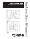
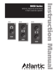
In-Wall Theater System Speaker
Instruction Manual
IWTS-4 LCR
2
Safety Precautions
IWTS-4 In-Wall Theater System Speaker
Table of Contents
2 Model IWTS-4 LCR
3 Important Considerations Before Installation
3
3
3
Recommended Wire Sizes
Location Considerations
Room Acoustics
3
3
4
Low Resonance Tweeter
Stereo Music Listening
Home Theater Systems
3 Speaker Placement
5 Mounting the IWTS-4 Speaker
5 Installation of the IWTS-4 in New Construction
5 Installation of the IWTS-4 in Existing Construction
5
5
6
6
6
6
Removing and Installing the Grille
Cutting the Opening
Installing the Mounting Frame
Painting the Speaker Assembly
Speaker Connection and Assembly
Installing the Speaker Enclosure Into the Frame
7 Front Panel Control
7
HF (High Frequency) Level Control
7 Specifications
For Future Reference
Record your serial numbers and date of purchase here:
Model Number
Serial Number
Date of Purchase
The serial number is found on the back panel.
Copyright © 2008 Atlantic Technology International.
Specifications are those in effect at the time of printing. Atlantic Technology reserves the
right to change specifications or designs at any time without notice.
Model IWTS-4 LCR
In Wall Theater System Speaker
Thank you for purchasing Atlantic Technology products. Our speaker systems have been designed to deliver exceptional sound and value. We hope
you like what you hear from them, and are happy with your decision to
buy them.
Please take a few moments to read these instructions. They’re intended not
only to tell you how to mount the speakers, but how to get the best performance from them.
Speaker Placement
Instruction Manual
Important Considerations Before
Installation
Recommended Wire Sizes
The longer the wire run, the heavier the wire should be. Use the following
recommendations as a guide for your installation. And if you’re in doubt,
remember that it never hurts to get the next heavier grade of wire. Also note
that lower gauge numbers equal heavier wire sizes.
Wire Run Wire Gauge:
<15 ft. 16 ga.
15 to 30 ft. 14 ga.
>30 to 50 ft. 12 ga.
Location Considerations
A major determinant of any speaker’s sound quality is its location in the
room. With in-wall speakers there are fewer placement options than with
free-standing speakers, so giving some thought to location can really pay
off. Our In-Wall Theater Systems have been designed to minimize the detrimental effects wall mounting can have on sound, so they sound better
than conventional in-wall speakers.
Room Acoustics
Hard surfaces create lots of sound reflections in the room while soft surfaces
tend to absorb sound. Note the speakers’ location in terms of proximity to
glass and other highly sound reflective or absorptive surfaces. A simple set
of curtains or an area rug can make a major difference in sound quality and
intelligibility by reducing excessive reflections.
3
Speaker Placement
For all the following situations, it’s recommended that you first place small
box speakers in the proposed locations, just to get a good idea of how
that location will sound. In-wall speakers are tough to move once they’re
installed!
For all the following placement instructions, it’s important to bear in mind
that for aesthetic considerations, many people prefer to mount their in-wall
speakers well above seated ear level, as doing so minimizes the speakers’
visual intrusion on the room.
Low Resonance Tweeter
Here’s the problem: The woofer in conventional in-wall speakers handles too
much of the midrange and woofers send out the midrange like a flashlight
beam—pretty much only straight ahead, with very little sound side-toside or up-and-down. So even if these speakers have a so-called “pivoting
tweeter,” that doesn’t really help, since it’s the woofer, not the tweeter, that
handles the directionally-critical midrange frequencies.
What’s needed is a speaker where the tweeter, not the woofer, handles more
of the midrange, because unlike woofers, tweeters spread their sound out
over a very wide area.
Because of this, Atlantic has engineered an extremely sophisticated, highperformance tweeter (the Low Resonance Tweeter, or LRT™) for the
IWTS-4, and it can play most of the middle tones as well, thereby relieving
the woofer of having to do what woofers can’t do. Our LRT tweeter spreads
out the midrange sound (“disperses” the sound) over a much wider angle
than the woofer, so the IWTS-4 covers the entire listening area beautifully
in both the midrange and treble, even when it’s mounted high up on the
wall.
Stereo Music Listening
For stereo music reproduction, place the speakers at approximately ear
level when seated, with both speakers on the same wall facing the prime
listening location. A separation of approximately 6 to 8 feet between the
left and right speakers is usually good. Ideally, the distance between the
two speakers will be close to the same as the distance from the speakers to
the listening position.
4
Home Theater Placement
IWTS-4 In-Wall Theater System Speaker
Home Theater Systems
Front Speaker Array should be
placed as close to ear level as
possible.
Left
Center
Optional Dipole/Bipole
Speakers should be
placed directly to the
sides of the seating area
and approximately
1-2 feet (.3-.6 meter)
above the listener’s ear
level.
Left
Dipole
Surround
or
Left
IWTS-4
Surround
Right
Subwoofer
Left/Center/Right Locations The tweeter in the front
three speakers should be at or just above ear height when
seated, just as with stereo speakers. Try to keep the vertical
position of the three front speakers within 18 inches of each
other, as this will maintain smooth, believable left-centerright pans.
Right
Dipole
Surround
or
Right
IWTS-4
Surround
Optional Direct Radiator Speakers
should be placed slightly behind the
listening position, above ear level.
Left
IWTS-4
Surround
Back
Today’s home theater systems require you to place six or
more speakers in your room. For the most convincing
theater effects, speaker placement must be very carefully
thought out. This is especially true with in-wall speakers,
since their installation is permanent!
Right
IWTS-4
Surround
Back
Optional Surround Back Speakers
should be placed approximately 1-2
feet (.3-.6 meter) above the listener’s
ear level. Direct radiators may be
used here.
The spacing of the left-right speakers can be a little wider
than with 2-channel stereo speakers, since in a theater system, the center channel speaker reproduces the on-screen
effects and anchors the center image. Left-right spacing of
about 8 to10 feet usually works well.
Surround Speakers In order to achieve optimum performance we strongly recommend Atlantic Technology Dipole
or TriVector™ surround speakers. If you are using our dedicated surround speakers please follow the placement recommendations included in their installation instructions.
Non-Dipole Surrounds The most realistic surround effects
occur when the listener can’t localize the actual location of
the surround speaker. If you decide to use the In-Wall Theater System speakers as surround speakers, mount them
above the listeners’ ears, slightly behind the listening area
either on the side or rear walls.
Installation
Instruction Manual
Mounting the IWTS-4 Speaker
NOTE: We always recommend a professional be involved in the
installation of IWTS-4 speakers.
The IWTS-4 speaker can be easily mounted in most any standard wall
material, from ½ to 1½ inches thick. Its rotating wall clamps (sometimes
called "dog legs") firmly fix it to the wall surface after the proper cutout has
been made. Here are some important precautions to take before mounting:
Keep the sides of the actual mounting hole at least ½ inch away from
beams or studs to ensure that the clamps have adequate room to rotate.
A stud or other obstruction that’s too close will stop them from properly
doing their job.
5
Installation of the IWTS-4 in Existing
Construction
Removing and Installing the Grille
Remove the grille from the speaker using an awl or the point of a drywall
screw in a grille opening near one of the grille corners. Slowly pry the grille
out, being careful not to damage the speaker’s frame or its finish.
To re-install the grille later, press it carefully into the appropriate opening in
the frame assembly. Since it’s designed to fit snugly, please take your time
and use care when installing the grille.
Cutting the Opening
Installation of the IWTS-4 in New
Construction
11”
(280mm)
Atlantic Technology offers an optional Rough-in Frame Kit (IN-NC-4) to
ease installation in new construction. Instructions for its use are included
with that kit.
Center
7 5⁄8”
(194mm)
IWTS-4
Mounting Template
After determining the best location for the speaker as outlined above, use
the enclosed template to cut the proper size hole.
IWTS-4 LCR
7 5⁄8” x 11”
WARNING: Exercise extreme care before making any wall cuts to
ensure that you will not cut through any wires, pipes, or other items
that may be in the wall. You may sometimes, but not always, be able
to determine the approximate location of wires and pipes by looking
at the locations of nearby outlets and plumbing. But their location or
absence is never an assurance that there is not something within the
wall cavity.
6
Installation
IWTS-4 In-Wall Theater System Speaker
Installing the Mounting Frame
Speaker Connection and Assembly
The clamping mechanism allows
the wall material to range from
½ to 1½ inches (13 to 38 mm) in
thickness. There must be a minimum depth behind the wall face of
3 5⁄8” (92 mm). As noted above, be
sure to keep the edges of the cutout at least ½ inch (13 mm) away
from any stud or obstruction, as
the rotating clamps will not operate properly if you don’t. Insert the
frame into the cutout and using a
level or square carefully align it
so it is level. Tighten the mounting screws, which will cause the attached
clamps to rotate and position themselves properly behind the wall.
Continue to tighten until the frame is snug in the wall. You want the bezel
to conform to the wallboard, and the frame not to rattle from the speaker’s
vibration, but be very careful not to overtighten the screws.
Painting the Speaker Assembly
The white plastic frame and the
metal grille may be left as is, or
painted to match your décor. You
can paint the frame before or after
it is installed in the wall. Spray
painting (using slightly thinned
paint) is the best method to use for
painting the grille. Before painting
the grille, carefully peel off the cloth
scrim. After painting the grille, use
air pressure to “blow out” any grille
holes that are filled in with paint.
Once the paint is dry, re-apply the scrim to the inside of the grille.
Strip about ½” (13 mm) of insulation from the connecting wires. Connect
them to the appropriate push terminal, being careful to observe polarity
(positive to the red terminal, negative to the black terminal).
Installing the Speaker Assembly into the Frame
Once the frame is mounted in the wall, the speaker simply fits into the
frame.
Use the included screws to attach the baffle to the mounting frame, but be
very careful not to overtighten the screws.
Front Panel Controls
Instruction Manual
Front Panel Control
HF (High Frequency) Level Control
This control adjusts the relative level of high frequency
output to compensate for varying room acoustics or
placement behind a screen.
“+” is for absorptive, acoustically “dead” rooms (or when
the speaker is behind a movie screen). Use this position
to increase the HF level and restore the proper sparkle and liveliness to
the sound.
“0” is for rooms of average absorptive characteristics.
“-“ should be used in rooms that are highly reflective, with hard floors
and exposed windows.
The setting of the HF control is mostly a matter of personal taste, so try it
in all three positions and see which one is preferred.
Should you have any questions or problems please feel free to contact us at
781-762-6300 or through our web site, www.atlantictechnology.com.
7
Specifications
IWTS-4 LCR
Type
2-way
Drivers
Woofer 6 ½” (165mm) GLH*
Tweeter 1" (25mm) LRT soft dome
Frequency Response 57Hz – 20kHz ±3dB
Nominal Impedance
6 Ohms
Crossover Frequency
2.4kHz, 3rd order
Sensitivity
88dB
Recommended Power
10 – 100 Watts RMS
Overall Dimensions (W x H x D)
8 ¾ x 12 1⁄8 x 3 ¾"
223 x 308 x 96mm
Cutout Dimensions
(W x H)
7 5⁄8 x 11”
194 x 280mm
Net Weight
6lbs; 2.7kg each
*Graphite Loaded Homopolymer
Specifications are those in effect at the time of printing. Atlantic Technology reserves the right
to change specifications or appearance at any time without notice.
343 Vanderbilt Avenue Norwood, MA 02062 (781) 762-6300 www.atlantictechnology.com
015-1004