1
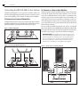
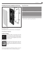
High Performance
In-Wall Subwoofer
Instruction Manual
IWTS-28 SUB
2
Safety Precautions
IWTS-28 SUB In-Wall Subwoofer
Table of Contents
2 Model IWTS-28 SUB
2 Important Considerations Before Installation
Model IWTS-28 SUB
In-Wall Subwoofer
2
3
Recommended Wire Sizes
Location Considerations
4
4
To Connect as a Powered Subwoofer
To Connect as a Passive Bass Module
Removing and Installing the Grille
Treating the Wall Cavity
Cutting the Opening
Installing the Mounting Frame
Painting the Speaker Assembly
Speaker Connection and Assembly
Installing the Speaker Enclosure Into the Frame
Please take a few moments to read these instructions. They’re intended not
only to tell you how to mount the speakers, but how to get the best performance from them.
Low-Pass Control
IR Knockout
Recommended Wire Sizes
4 Connecting the IWTS-28 SUB to Your Sustem
5 Mounting the IWTS-28 SUB
5 Installation of the IWTS-28 SUB in New Construction
5 Installation of the IWTS-28 SUB in Existing Construction
5
5
5
6
6
6
6
7 Front Panel Controls
7
7
7 Specifications
Thank you for purchasing Atlantic Technology products. Our speaker systems have been designed to deliver exceptional sound and value. We hope
you like what you hear from them, and are happy with your decision to
buy them.
Important Considerations Before
Installation
The longer the wire run, the heavier the wire should be. Use the following
recommendations as a guide for your installation. And if you’re in doubt,
remember that it never hurts to get the next heavier grade of wire. Also note
that lower gauge numbers equal heavier wire sizes.
Wire Run Wire Gauge:
<15 ft. 16 ga.
15 to 30 ft. 14 ga.
>30 to 50 ft. 12 ga.
For Future Reference
Record your serial numbers and date of purchase here:
Model Number
Serial Number
Date of Purchase
The serial number is found on the back panel.
Copyright © 2008 Atlantic Technology International.
Specifications are those in effect at the time of printing. Atlantic Technology reserves the
right to change specifications or designs at any time without notice.
3
Speaker Placement
Instruction Manual
Location Considerations
Choosing the location for the subwoofer is a very important consideration.
Since the IWTS-28 SUB can't easily be moved once it’s installed (!), very
careful consideration should be given to its placement. In general, the cleanest and most articulate delivery of bass energy into the room occurs when
the subwoofer is placed asymmetrically with respect to the room’s dimensions. (see fig. 1). Such placement generally results in the best overall balance of bass impact vs.‘one-note boom.’
If you are using two 28 SUB modules, follow the same advice: locate them
asymmetrically within the room (i.e. one near a corner, one towards the
middle of a wall) to smooth out the bass and minimize random standing
wave patterns. (see fig. 2)
Figure 2 – Dual Sub Placement
14'
Figure 1 – Asymmetrical Placement
5'
Good
5'
18'
Good
13'
Good
18'
13'
3'
11'
4
Connections
IWTS-28 SUB In-Wall Subwoofer
Connecting the IWTS-28 SUB to Your System
To Connect as a Passive Bass Module:
The IWTS-28 SUB may be used as a passive bass module to reinforce the
bass from the left/right front speakers in your system, or it may be powered
by an external amplifier (such as Atlantic’s SA-180 mono bloc amplifier).
Remove the jumpers from the 28 SUB’s terminals (see fig. 4). Run speaker
wires from the receiver’s front left speaker terminals to one set of terminals on the 28 SUB. Run another set to the other set of terminals on the
28 SUB. (see fig. 5) It does not matter which woofer on the 28 SUB is considered ‘right’ or ‘left,’ since bass is generally recorded in mono, and is nondirectional anyway. Be careful to observe consistent polarity between the
two woofers, and between the woofers and front L/R speakers. All reds and
blacks should be consistent.
To Connect as a Powered Subwoofer:
Leaving the jumpers in place, connect the speaker wires from the SA-180 to
one black terminal and one red terminal on the 28 SUB. Make sure the 28
SUB’s front-panel low-pass switch is in the off position (see fig. 3).
Figure 3 – IWTS-28 SUB jumpers
Be sure to switch the 28 SUB’s front panel low-pass switch to “on.” This will
filter out any signal above around 200 Hz from reaching the 28 SUB module,
and ensures that only the non-directional lower frequencies are being fed to
the SUB, thus preserving your system’s front-channel sonic imaging.
Important note: Each individual woofer in the 28 SUB is 8 ohms;
when connecting them in parallel with your front L/R speakers (as you
do when using the 28 SUB passively), the front L/R speakers need to
also be 8 ohms minimum, so that their combined paralleled impedance does not fall below 4 ohms. Consult your receiver’s owner’s
manual for more information on its impedance drive capability.
Figure 4 – Removing the IWTS-28 SUB jumpers
Figure 5 – Connecting as a Passive Bass Module
LEFT
RIGHT
SURROUND SURROUND
+
+
–
LEFT
+
–
CENTER
+
–
RIGHT
–
+
–
Installation
Instruction Manual
Mounting the IWTS-28 SUB
NOTE: We always recommend a professional be involved in the
installation of IWTS speakers, if at all possible.
You will need the Grille/Frame assembly GFR-626, sold separately.
The GFR-626 can be easily
mounted in most any standard
wall material, from ½ to 1½
inches thick. Its rotating wall
clamps (sometimes called “dog
legs”) firmly fix it to the wall
surface after the proper cutout
has been made. Here are some
important precautions to take
before mounting:
Keep the sides of the actual
mounting hole at least 1½ inches
away from beams or studs to
ensure that the clamps have adequate room to rotate. A stud or other
obstruction that’s too close will stop them from properly doing their job.
5
Treating the Wall Cavity
The IWTS-28 SUB does not require a back box. It is designed to work properly in a standard full-sized wall cavity. This is commonly called an “infinite
baffle” installation. However even though there is no back box, you should
exercise good acoustic/mechanical common sense, and prepare the wall
cavity as follows:
•Make sure there are no extraneous house electrical wires, plumbing,
junction boxes, or other items that could rattle or vibrate from the 28
SUB’s output. A subwoofer moves a considerable amount of air, and if
something can rattle, it probably will rattle. It’s much, much easier to
‘button everything down’ securely before you install the sub then it is
to try to hunt down an intrusive buzz or rattle later on.
•Seal all the stud-to-drywall seams with a flexible silicone construction
caulk. This will help keep the drywall itself from flexing and rattling
against the studs, and it helps form a more airtight “enclosure” for the
28 SUB.
•Fill the wall cavity loosely with acoustic speaker stuffing (“polyfill”). It
is not necessary to pack the stuffing in extremely tight; in fact, that will
reduce the bass output.
Installation of the IWTS-28 SUB in New
Construction
Atlantic Technology offers an optional Rough-in Frame Kit to ease installation in new construction. Instructions for its use are included with this
kit. Ask your Atlantic dealer for more details. The kit’s model number is
IN-NC-626.
Installation of the IWTS-28 SUB in Existing
Construction
Removing and Installing the Grille
Remove the grille from the speaker using an awl or the point of a drywall
screw in a grille opening near one of the grille corners. Slowly pry the grille
out, being careful not to damage the speaker’s frame or its finish.
To re-install the grille later, press it carefully into the appropriate opening in
the frame assembly. Since it’s designed to fit snugly, please take your time
and use care when installing the grille.
•If this is new construction, we strongly recommend using 5⁄8” or ¾”
sheetrock. It’s heavier and more expensive than ½” material, but it’s far,
far superior in terms of acoustic/mechanical integrity and rigidity. We
also strongly recommend that the sheetrock be screwed to the studs
every 6 inches or so, instead of the more common practice of nailing
it every 12-18”. Use screws for at least a full stud bay on either side of
where the 28 SUB will be mounted.
•If you drill a hole in the stud to snake the speaker wires through, be
certain to seal that hole with silicone caulk.
6
Installation
IWTS-28 SUB In-Wall Subwoofer
Cutting the Opening
Painting the Speaker Assembly
The white plastic frame and the
metal grille may be left as is, or
painted to match your décor. You
can paint the frame before or after
it is installed in the wall. Spray
painting (using slightly thinned
paint) is the best method to use
for painting the grille. Be sure to
remove the scrim cloth before
painting the grille. After painting
the grille, use air pressure to “blow
out” any grille holes that are filled
in with paint. Then re-apply the
scrim cloth.
20 3⁄8”
(518mm)
11 1⁄8”
(283mm)
IWTS-30 LCR
Mounting Template
Mount frame as shown,
with IR knockout in
upper-right corner.
Remove scrim before
painting grille.
After determining the best location for the speaker as outlined above, use
the template included with the GFR-626 to cut the proper size hole.
Speaker Connection and Assembly
WARNING: Exercise extreme care before making any wall cuts to
ensure that you will not cut through any wires, pipes, or other items
that may be in the wall. You may sometimes, but not always, be able
to determine the approximate location of wires and pipes by looking
at the locations of nearby outlets and plumbing. But their location or
absence is never an assurance that there is not something within the
wall cavity.
Installing the Mounting Frame
The clamping mechanism allows
the wall material to range from
½ to 1½ inches (13 to 38 mm) in
thickness. There must be a minimum depth behind the wall face
of 3-5⁄8” (92 mm). As noted above,
be sure to keep the edges of the
cutout at least 1½ inch (38mm)
away from any stud or obstruction, as the rotating clamps will
not operate properly if you don’t.
The speaker baffle is designed
to mount into the white frame,
after the frame is mounted into
the wall.
Insert the frame into the cutout and using a level or square carefully align
it so it is level. Tighten the mounting screws, which will cause the attached
clamps to rotate and position themselves properly behind the wall.
Continue to tighten until the frame is snug in the wall. You want the bezel
to conform to the wallboard, and the frame not to rattle from the speaker’s
vibration, but be very careful not to overtighten the screws.
Strip about ½" (13 mm) of insulation from the connecting wires. Connect
them to the appropriate push terminal, being careful to observe polarity
(positive to the red terminal, negative to the black terminal).
Specifications
Instruction Manual
Installing the Speaker Assembly into the Frame
7
Specifications
IWTS-28 SUB
Overall Dimensions (W x H x D)
12 5⁄16 x 215⁄8 x 3 7⁄8" (312 x 547 x 100mm)
Cut-out Dimensions (W x H) 111⁄8 x 20 3⁄8” (283 x 518mm)
Drivers/Design Dual 8” (203mm) long-throw, 40mm voice coils
Frequency Response 38-200 Hz +/- 3dB, passive response
Recommended Amplifier Power 30-200 Watts RMS
Low-pass Filter Frequency 200 Hz
Sensitivity 89dB
Impedance Each individual woofer 8 ohm; paralleled 4 ohms
Required Grille/frame assembly GFR-626
Specifications are those in effect at the time of printing. Atlantic Technology reserves the right
to change specifications or appearance at any time without notice.
Once the frame is mounted in the wall, the speaker assembly simply fits
into the frame as shown.
Use the included screws to attach the enclosure to the mounting frame.
Front Panel Controls
Low-Pass Control
The IWTS-28 SUB has a front-mounted control that
selects or bypasses the speaker’s built-in low-pass
corossover. Leave this in the off position when using the
28 SUB with an outboard amplifier and your receiver’s
low-pass crossover.
IR Knockout
There’s an IR “knockout” plug in the upper right corner
of the baffle. If you are using a multi-room control system, you can install a standard IR receiver in the knockout hole.
Should you have any questions or problems please feel free to contact us at
781-762-6300 or through our web site, www.atlantictechnology.com.
343 Vanderbilt Avenue Norwood, MA 02062 (781) 762-6300 www.atlantictechnology.com
015-1028