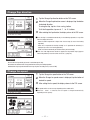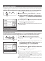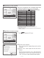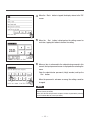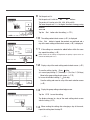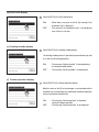
1
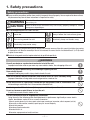
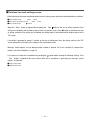
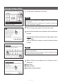
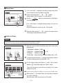
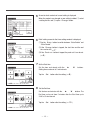
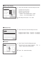
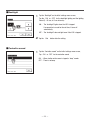
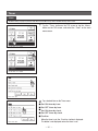
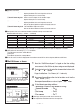
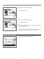
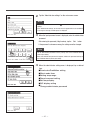
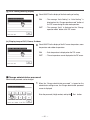
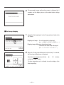
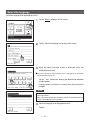
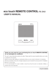
eco touch REMOTE CONTROL RC-EX1 USER’S MANUAL Thank you very much for your purchasing the eco touch REMOTE CONTROL for our packaged air conditioner. This user’s manual describes cautions for safety. Please read this manual carefully before use in order to operate the unit properly. Keep this manual, after reading, at a safe place where you can consult it whenever it is necessary. When the ownership of the unit is changed, please be sure to transfer this manual and the “Installation Manual” (in CD-R) to a new owner. It is not recommended for a user to install or move the unit by the user’s on discretion. (Safety or functions may not be assured.) PJZ012A091 Contents 1. Safety precautions ………………… 2 2. Functions and menu items of Remote Control (R/C) ………………………… 4 3. Quick reference of menu items ………8 4. Menu items ………………………… 10 Run/Stop ………………………………………… 10 Change operation mode ………………………… 11 Change set temperature ………………………… 11 Change flap direction …………………………… 12 Change fan speed ……………………………… 12 High power operation …………………………… 13 Energy-saving operation ………………………… 13 Energy-saving settings ………………………… 17 Individual flap control …………………………… 22 External ventilation ……………………………… 25 Initial settings …………………………………… 26 Timer ……………………………………………… 30 Weekly timer ……………………………………… 34 Home leave mode ……………………………… 38 Administrator settings …………………………… 41 Select the language ……………………………… 52 5. Maintenance ……………………… 53 6. Useful information………………… 55 Error display ……………………………………… 55 7. After-sale service ………………… 57 —1— 1. Safety precautions Safety precautions ●Please read the precautions written here carefully to operate the unit properly. You are required to observe these fully because every item of these instructions is important for safety. WARNING Failure to follow these instructions may result in serious consequences such as death, severe injury, etc. CAUTION Failure to follow these instructions may cause injury, property damage or, serious consequences depending on. ●The following pictograms are used in the text. Never do. Always follow the instructions given. Be sure to ground the unit. Absolutely keep wet hands away. Absolutely keep water away. ●Keep this manual at a safe place where you can consult with whenever necessary. Show this manual to installers when moving or repairing the unit. When the ownership of the unit is transferred, this manual and the “Installation Manual” (in CD-R) should be given to a new owner. ●Electrical wiring work must be implemented only by qualified specialists. WARNING Consult your dealer or a professional contractor to install the unit. Improper installation made on your own may cause electric shocks, fire or dropping of the unit. Consult your dealer when moving, disassembling or repairing the unit. Never modify the unit. Improper handling may result in injury, electric shocks, fire, etc. Take care to protect terminal connections from external forces or stress caused by wiring. Improper connection or fixing could cause heat generation, smoke or fire. Do not install the unit at a place where inflammable gas may generate, flow in, accumulate or leak. Inflammable gas could catch fire if it accumulates around the unit. Avoid using combustible substances (hair spray, insecticide, etc) near the unit. Do not use benzene or paint thinner to clean the unit. It could cause cracks, electric shocks or fire. The unit should not be used in inappropriate environment. Using the unit at the following places could deteriorate its performance significantly or cause electric shocks, break-down, smoke or fire as a result of corrosion. ∙ Where air contains dense oil mist, steam, organic solvent vapor, corrosive gas (ammonium, sulfuric compound, acid, etc) ∙ Where acidic or alkaline solution, cosmetics, special spray, etc. are used frequently ∙ Where oil mist generates ∙ Where dense cigarette smoke exists ∙ Where dust floats in air ∙ Where water vapor generates or heavily humid area —2— The maximum voltage connectable to the remote control is DC 18 V. Do not connect to AC220~240V or 380/415V. It could cause breakage, ignition or fire. Stop operation under abnormal situation. If continued, it could result in break-down, electric shocks, fire, etc. If any abnormal condition (burnt odor etc.) occurs, stop operation, turn off the power switch and consult your dealer. Stop operation when any anomaly is detected. If operation is continued, it could cause fire or break-down. Consult you dealer. CAUTION Do not use or let use the unit or remote control as play equipment. Improper operations could cause ill health or health disorder. Never disassemble the remote control. If you touch internal parts accidentally, you could get electric shocks or cause trouble. Consult your dealer when it is necessary to inspect its interior. Do not wash the remote control with water or liquid. It could cause electric shocks, fire or break-down. Do not install the remote control where it may be splashed with water. If water gets into the device accidentally, it could cause electric shocks or breaking electronic parts. Do not touch electric parts or operate buttons or screens with wet hands. It could cause electric shocks, fire or break-down. Be sure to stop operation and shut down the circuit breaker before starting maintenance work. It could cause electric shocks or injury. Install the remote control securely where it can be stable. Insufficient strength or improper installation could cause the remote control to drop off. Do not dispose the remote control by yourself. It could destruct the environment. Ask your dealer when it is necessary to dispose the remote control. The remote control should not be installed where it is exposed to direct sunlight or the ambient temperatures become higher than 40°C or lower than 0°C. It could cause deformation, discoloration or break-down. Do not use benzene, paint thinner, wipes etc. to clean the remote control. It could discolor or break-down the remote control. Wipe it with a piece of cloth which is squeezed tightly after wetting with diluted neutral detergent. Finish up the cleaning by wiping with a piece of dry cloth. Do not pull or twist the cable of the remote control. It could cause break-down. Do not tap the remote control buttons or screen with pointed objects. It could damage or cause break-down. —3— 2. Functions and menu items of the Remote Control Names and functions of sections on the R/C (Operating section) ⑤LCD display (With backlight) ③ switch ④Operation lamp ⑥USB port (mini-B) ① ② switch switch Touch panel system, which is operated by tapping the LCD screen with a finger, is employed for any operations other than the ① Run/Stop, ② High power and ③ Energy-saving switches. ① switch (Run/Stop switch) ne push on the button starts operation and O another push stops operation. (☞page 10) ② switch (High Power switch) Pushing this button starts the high power operation. (☞page 13) switch (Energy Saving switch) ③ If the backlight is ON setting, when the screen is tapped while the backlight is turned off, the backlight only is turned on. (Operations with switches ①, ② and ③ are excluded.) ⑥ USB port USB connector (mini-B) allows connecting to a personal computer. For operating methods, refer to the instruction manual attached to the software for personal computer (eco-touch remote control RC-EX1, utility software). P ushing this button starts the energy-saving operation. (☞page 13) ④ Operation lamp This lamp lights in green (yellow-green) during operation. It changes to red if any error occurs. Note ⑤ LCD (With backlight) · When connecting to a personal computer, do not connect A tap on the LCD lights the backlight. simultaneously with other USB devices. The backlight turns off automatically if there is no Please be sure to connect to the computer directly, without operation for certain period of time. going through a hub, etc. Lighting period of the backlight lighting can be changed. (☞page 29) —4— Names and functions of sections on R/C (Display) * All icons are shown for the sake of explanation. TOP screen ①Clock, R/C name display ②Icon display ③Menu button ⑤Change set temp button ④Change operation mode button ⑥Change flap direction button ⑧Timer button ⑦Change fan speed button ⑨Message display ① Clock, R/C name display Displays the current time ( ☞page 27) and the name of R/C (☞page 47) ② Icon display Each icon is displayed when one of following settings is going on. When the demand control When setting is made from the sub R/C. is effective. (☞page 14) When the central control When the periodical inspection is necessary. (Optional) is running. (☞page 55) During the ventilation operation (☞page 25) When ”filter sign” is up. (☞page 53) When the Permission/ When the weekly timer Prohibition setting is made. is set. (☞page 43) (☞page 34) When the peak-cut timer is set. (☞page 18) ③ Menu button When setting or changing other than the following ④-⑧, tap the menu button. When menu items are displayed, select one and set. ④ Change operation mode button (☞page 11) Displays the operation mode which is selected currently. Tap this button to change the operation mode. ⑤ Change set temp button (☞page 11) Displays the temperature which is set currently. Tap this button to change the set temperature. ⑥ Flap direction button (☞page 12) Displays the flap direction which is selected currently. Tap this button to change the flap direction. ⑦ Fan speed change button (☞page 12) Displays the fan speed which is selected currently. Tap this button to change the fan speed. ⑧ Timer button (☞page 30) Displays simplified contents of the timer which is set currently. (When two or more timers are set, contents of the timer which will be operated immediately after is displayed.) Tap this button to set the timer. ⑨ Message display Status of air conditioner operation and messages of the R/C operations etc. are displayed. —5— Menu item Main menu Basic operation …………………………………………………………………… 10 Run/Stop ………………………………………………………… 10 Change operation mode ………………………………………… 11 Change set temp ………………………………………………… 11 Change flap direction …………………………………………… 12 Change fan speed ……………………………………………… 12 High power operation …………………………………………… 13 Energy-saving operation………………………………………… 13 Energy-saving setting …………………………………………………………………… 17 Sleep timer ……………………………………………………… 18 Peak-cut timer …………………………………………………… 18 Automatic temp set back ……………………………………… 21 Individual flap control …………………………………………………………………… 22 Ventilation …………………………………………………………………… 25 Initial settings …………………………………………………………………… 26 Clock setting ……………………………………………………… 27 Date & time display ……………………………………………… 28 Summer time……………………………………………………… 28 Contrast …………………………………………………………… 28 Backlight ………………………………………………………… 29 Controller sound ………………………………………………… 29 Timer …………………………………………………………………… 30 Set ON timer by hour …………………………………………… 31 Set OFF timer by hour …………………………………………… 33 Set ON timer by clock …………………………………………… 33 Set OFF timer by clock ………………………………………… 33 Confirm …………………………………………………………… 34 Weekly timer …………………………………………………………………… 34 Home leave mode …………………………………………………………………… 38 Administrator settings …………………………………………………………………… 41 Permission/Prohibition setting ………………………………… 43 Silent mode timer ………………………………………………… 44 Setting temp range ……………………………………………… 45 Temp increment setting ………………………………………… 46 R/C display setting ……………………………………………… 47 Change administrator password ……………………………… 50 Change set temp display ……………………………………… 51 Select the language …………………………………………………………………… 52 Filter sign reset …………………………………………………………………… 53 …………………………………………………………………… 55 Comtact company & Error display —6— Main menu Installation settings …………………………………………………… Installation date ………………………………… Company information …………………………… Test run …………………………………………… Static pressure adjustment Change auto-address Address setting of main IU IU back-up function ……………………………… R/C settings …………………………………………………… Main/Sub of R/C ………………………………… Return air temp…………………………………… R/C sensor ……………………………………… R/C sensor adjustment ………………………… Operation mode ………………………………… Select operation mode ………………………… ˚C / ˚F ……………………………………………… Fan speed ………………………………………… External input …………………………………… Ventilation setting………………………………… Fan control ……………………………………… Auto-restart ……………………………………… Auto temp setting………………………………… Auto fan speed …………………………………… IU settings …………………………………………………… High ceiling ……………………………………… Filter sign ………………………………………… External input 1…………………………………… External input 1 signal …………………………… External input 2…………………………………… External input 2 signal …………………………… Heating thermo-OFF temp adjustment ……… Return air sensor adjustment …………………… Fan control in cooling thermo-OFF …………… Fan control in heating thermo-OFF …………… Anti-frost temp …………………………………… Anti-frost control ………………………………… Drain pump operation …………………………… Residual fan operation in cooling ……………… Residual fan operation in heating ……………… Intermittent fan operation in heating…………… Fan circulator operation ………………………… Control pressure adjust ………………………… Auto operation mode …………………………… Thermo. rule setting……………………………… Auto fan speed control ………………………… IU overload alarm ………………………………… Service & Maintenance …………………………………………………… IU address ………………………………………… Next service date ………………………………… Check run mode ………………………………… Operation data …………………………………… Saving IU settings ……………………………… Special settings ………………………………… —7— Please refer to [Installation manual] 3. Quick reference of menu items Administrator password It is necessary to input the Administrator password for menu items showing. Setting and display items Details Reference Set the time period from start to stop of operation. ■The selectable range of setting time is from 30 to 240 minutes (at 10-minute intervals). ■When the setting is “Enable”, this timer will activate whenever any operation starts. 17 page Set the times to start and stop the capacity limiting operation and the peak-cut %. ■Peak-cut 40% means operating at 40% of nominal capacity ■4 operation patterns per day can be set at the maximum. ■The setting time can be changed at 5-minute intervals. ■The selectable range of peak-cut % is from 0 to 80% (at 20% intervals). ■Holiday setting (including temporary day off) is available. * Clock setting is necessary. 18 page It returns to the set temperature when the set time is counted up. ■The selection range of the set time is from 20 to 120 minutes (at 10-minute intervals). 21 page Individual flap control Set the moving range (upper and lower limit positions) of the flap at each air outlet of IU. 22 page External ventilation The ventilation is turned on or off. ■If the ventilation is set at “Independent operation”, the ventilator can be turned on/off without any combination of the IU operation. 25 page Filter sign reset Reset the filter sign. Set next cleaning date. 53 page Set and correct the current date and time. ■When the power supply is interrupted for 80 hours or less, the clock continues to operate with the built-in backup batteries. If it is interrupted for more than 80 hours, it is necessary to renew the setting. 27 page Energy-saving setting Sleep timer Administrator password Peak-cut timer Automatic temp set back Initial settings Clock setting Date & time display Set whether the date and time are displayed or not, and select 12H 28 page or 24H. Timer Summer time Contrast Backlight Controller sound Current time is advanced or delayed by 1 hour. Select whether the controller sound is actuated at the touch panel operation or not. 29 page Set ON timer by hour Set OFF timer by hour Set ON timer by clock Set the time to operate the unit after stopping the operation within the range of 1 – 12 hours (at 1-hour intervals). 31 page Set the time to stop the operating unit within the range of 1 – 12 hours (at 1-hour intervals). 33 page Set the clock time to start operation. ■The time can be set at 5-minute intervals. ■It can be selected from once (only one day) or every time (every day). * Clock setting is necessary to set the timer. 33 page Set OFF timer by clock Set the time to stop operation. ■The time can be set at 5-minute intervals. ■It can be selected from once (only one day) or every time (every day). * Clock setting is necessary to set the timer. 33 page 28 page Contrast of LCD can be adjusted. 28 page Select whether the backlight is used or not, and set the lighting time. 29 page —8— Setting and display items Weekly timer Reference On timer or Off timer on weekly basis can be set. ■8-operation patterns per day can be set at the maximum. ■The time can be set at 5-minute intervals. ■Holiday setting (including temporary day off) is available. * Clock setting is necessary to set the time. 34 page When the unit is not used for a long period of time, the room temperature is maintained at a moderate level, avoiding extremely hot or cool temperatures. ■C ooling or heating is operated according to the outdoor temperature and the set temp. ■Set temp and fan speed can be set. 38 page Permission/ Prohibition setting Set the permission/prohibition for each of following operations: [Run/Stop], [Change set temp], [operation mode], [Change flap direction], [Individual flap control], [Change fan speed], [High power operation], [Energy-saving operation], [Timer] and [Weekly timer] 43 page Silent mode timer The period of time to operate the unit by prioritizing the quietness can be set. ■Starting and stopping times for the silent mode operation can be set at 5-minute intervals. * Clock setting is necessary to set the time. 44 page Restrict the setting range of temperature. ■Temperature range can be restricted depending on operation modes. 45 page Set the interval for setting temperature (0.5°C/1.0°C). 46 page Register the names of remote control and indoor unit. Set Yes or No for the need of indoor temperature display. Set Yes or No for the need for the display of error code, heating standby, defrosting operation on and automatic cooling/heating. 47 page Change the administrator password. 50 page Set temperature display method can be selected. Select a actual temperature or the difference from the base temp such as +1,+2°C or -1,-2°C. 51 page Home leave mode Administrator password Administrator settings Details Administrator password Setting temp range Temp. increment setting RC display setting Change administrator password Set temp display Select the language Contact campany & Error display Set the language to be displayed on the R/C. Address of the service contact is displayed. —9— 52 page 55 page 4. Menu items Run/Stop 1 Run Push the Operation lamp (green) lights and operation starts. switch. 2 Stop Push the The operation lamp turns off and the operation stops. switch. When the operation stops, all operation buttons on the screen turn off. When the set lighting time of backlight (☞page 29) is counted up, the backlight turns off. When the screen is tapped, the backlight lights, and all operation buttons are displayed. Note · Do not shut down the power supply immediately after the stop of operation. It should be waited for more than 5 minutes till the residual operation time of drain motor is counted up. Otherwise, it could cause water leakage or breakdown. Advice · A message ”Invalid request” may be displayed when a button is pushed. This is not a fault but it is because the button operation is set to the “Disable”. (☞page 39) · The unit starts to operate initially with the following settings after the power on. These settings can be changed as desired. Operation mode … With auto mode: Auto cooling Without auto mode: Cooling Set temp … 23.0°C Fan speed … High Flap position … Level · In the following cases, a message “Operation mode invalid” is displayed and it changes to the fan operation, because operation modes are not matched. When different operation modes are selected between IUs which are connected to a OU that do not allow mixed operation of cooling and heating. — 10 — Change operation mode 1 Tap the Change operation mode button on the TOP screen. 2 When the Change operation mode screen is displayed, tap the button of desired mode. 3 When the operation mode is selected, the display returns to the TOP screen. Icons displayed have the following meanings. Cooling Fan Dry Heating Auto ■Operation modes which cannot be selected depending on combinations of IU and OU are not displayed. ■W hen the Auto is selected, the cooling and heating switching operation is performed automatically according to indoor and outdoor temperatures. Change set temp 1 Tap the Set temp button on the TOP screen. 2 When the Change set temp screen is displayed, select the temperature as desired with using ▲ ▼ buttons. 3 After selecting the set temp, tap the Set button. 4 The display returns to the TOP screen after tapping the Set button. ■For allowable temperature setting ranges, refer to the range setting of set temp (☞page 45). ■Reference set temp Cooling … 26 to 28°C Dry … 24 to 26°C Heating … 20 to 24°C Fan … Setting temp is not required. ■I f the Auto is selected for the set temp, the set temp display shows “0”. Temperature can be selected within the range of -6°C to +6°C with using ▲ ▼ buttons. Temperature increases by 1°C at each tap on the ▲ button or decreases by 1°C at each tap on the ▼ button. (If “0” is set, it becomes 24°C for the cooling operation or 26°C for the heating operation.) ■If the Back button is tapped without tapping the Set button, the selected set temp is invalidated and the display returns to the TOP screen. — 11 — Change flap direction 1 Tap the Change flap direction button on the TOP screen. 2 When the Change flap direction screen is displayed, tap the button for desired direction. To swing the flap, tap the Auto swing button. To fix the flap position, tap one of 1 to 4 buttons. 3 After selecting the flap direction, the display returns to the TOP screen. ■Since the flap is controlled automatically in the following operation, it may differ from the display on the R/C. ∙When the room temperature is higher than the set temp (In case of the heating operation) ∙When the “In operation for heating standby” or “In operation for defrosting” is displayed (In case of the heating operation) (Cool air is blown horizontally not to blow directly to human body.) ■When the Ind. flap control button is tapped, the flap motion range (upper or lower limit position) at each air outlet can be set. (☞page 23) Request · Do not move the flap forcibly by hands. It could damage the flap. ·D o not blow air downward for a long period of time during the cooling operation. Condensation may be generated and water may drip from the side panel. (In case of FDE) Change fan speed 1 Tap the Change fan speed button on the TOP screen. 2 When the Change fan speed screen is displayed, tap the button of desired fan speed. 3 After setting the fan speed, the display returns to the TOP screen. ■Fan speeds which can be set vary depending on the models of IU. ■W hen the Auto is selected, the fan speed is changed automatically depending on the capacity. — 12 — High power operation The high power operation adjusts the room temperature quickly to a pleasant level by increasing the operation capacity. The high power operation continues for 15 minutes at the maximum and returns to the normal operation automatically. When the operation mode is changed, the high power operation returns to the normal operation, too. 1 Push the switch to start the high power operation. ■O peration will start when the switch is pushed, even if switch is off. 2 Message “In operation for high power” is displayed on the R/C screen, and “—, —°C” is displayed on the Set temp button during the high power operation. 3 One more push on the switch terminates the high power operation. Then it returns to normal operation. switch stops the operation. Pushing the ■The high power operation is terminated also when the operation mode, set temp or fan speed is changed. Energy-saving operation Use this operation to save energy. Set temp is fixed at 28°C in the cooling operation or 22°C in the heating operation. Since the capacity is controlled automatically based on the outdoor temperature, energy can be saved without losing comfort. 1 Push the switch to start the energy-saving operation. ■The operation will start when the switch is pushed, even if switch is off. 2 Message “In operation for energy-saving” is displayed on the screen during the energy-saving operation. Set temp is fixed at 28.0°C” in the cooling operation or “22.0°C” in the heating operation. Set temp shows “- -°C” in the automatic operation mode. 3 One more push on the switch, terminates the energy-saving operation, and it changes to the normal operation. Pushing the switch stops the operation. ■S et temp cannot be changed during the energy-saving operation. If it is attempted, a message “Invalid request” is displayed on the screen. ■E nergy-saving operation is operable only when the cooling, heating or auto is switch is pushed in any operation selected for the operation mode. If the mode other than the cooling, heating or auto mode, the message “Invalid request” is displayed on the R/C screen. ■E nergy-saving operation is terminated also when the operation mode is changed. — 13 — ■Restrictions on the sub R/C When one IU is controlled with 2 R/Cs, the following settings cannot be made on the sub R/C. It is necessary to use the main R/C. In case of the sub R/C, the icon S is displayed on the R/C screen. Basic operation High power operation Energy-saving operation Energy-saving setting Individual flap control External ventilation Filter sign reset Initial settings Timer Weekly timer Home leave mode Administrator settings Installation settings R/C settings IU settings Service & Maintenance Select the language Error display & Error display Main Sub *1 *2 *3 *4 *1Warming up function cannot be set. *2 R/C display setting, Set temp display and Change administrator password can be set. *3 Main/Sub of R/Cs can be set. *4 IU address, Error display, Error history, Reset periodical check, CPU reset and Touch panel Calibration can be made. ■Operations on menu screens 1 Tap the Menu button on the TOP screen. 2 Main menu screen is displayed. When a desired menu item is tapped, setting screen for each item is displayed. 3 When the Next button is tapped, next main menu screen is displayed. When there are two or more pages, the Next button is displayed at the leading page and the Previous button is displayed at the last page. The Next and Previous buttons are displayed on pages in between. — 14 — 4 When the Back button is tapped, the display returns to the TOP screen. 5 When the Set button is displayed on the setting screen for each item, tapping this button to confirm the setting. 6 When an item is referenced to the administrator password in this manual, the Input password screen is displayed after selecting the menu. Enter the administrator password (4-digit number) and tap the Set button. When the password is unknown or wrong, the setting cannot be changed. Note ·For the administrator password at the factory setting, refer to the Installation Manual (consult your dealer). When your administrator password is forgotten, initialize the password by referring to the Installation Manual (consult your dealer). — 15 — ■Cautions for each setting screen · When returning to the screen mentioned below from each setting screen, operate the following buttons or switches. button ■Return to Main screen … Menu button ■Return to the last previous screen… Back switch … ■Return to TOP screen · When the Back button is tapped without tapping the Set button on the way of setting, contents of the switch is pushed on the way setting are invalidated, and the display returns to the last previous screen. If the of setting, contents of the setting are invalidated, the setting mode is terminated and the display returns to the TOP screen. ·If no button is operated for approx. 5 minutes on the way of setting each item, the display returns to the TOP screen automatically. Contents of the setting on the way become invalid. ·Message ”Invalid request” may be displayed when a button is pushed. This is not a fault but it is because the button is set to the Prohibition. (☞page 43) switch before starting the following settings. If the · It is necessary to stop the air conditioner by pushing the Set button is tapped on the menu screen while the air conditioner is operating, the message “Invalid request” is displayed. ■Energy-saving setting ■Administrator setting — 16 — Energy-saving setting 1 Tap the Menu button on the TOP screen. Note ·Always stop the air conditioner with the switch before starting the energysaving operation. If the “Energy-saving setting” is tapped while the air conditioner is operating, the message “Invalid request” is displayed. 2 Tap the “Energy-saving setting” on the main menu screen. 3 When the Input password screen is displayed, enter the administrator password. After entering the administrator password (4-digit number), tap the Set button. When the password is unknown or wrong, the setting cannot be changed. Note ·For the administrator password at the factory setting, refer to the Installation Manual (consult your dealer). When your administrator password is forgotten, initialize the password by referring to the Installation Manual (consult your dealer). 4 When the Energy-saving setting screen is displayed, select a desired item. ■ Sleep timer ■ Peak-cut timer ■ Automatic temp set back — 17 — ■Sleep timer 1 If the “Sleep timer” is tapped on the Energy-saving setting menu screen, contents of current setting are displayed. 2 Select a desired time with ① 1 2 ▲ ▼ buttons. Setting range: 30 to 240 minutes, at 10-min intervals 3 Tap the ② State and “State Disable”. button to switch between “State Enable” If the “State Enable” is selected, operation stops at the set time 3 every time. Unless the Sleep timer is used, set at the “State Disable”. 4 After the setting, tap the ③ Set button. The display returns to the Energy-saving setting menu screen. ■Peak-cut timer Advice · When the peak-cut timer is used, be sure to make the Clock setting in advance (☞page 27). · The peak-cut timer control may not be performed depending on combination of IU and OU. 1 When the screen to select the setting range, select a day of the week to be set. ①Weekdays: Monday – Friday ②Sat. Sun : Saturday, Sunday (☞4 ) ③All days : Monday - Sunday oves to the day of the week setting screen. (☞2 ) ④Each day : M 1 2 3 4 2 If a desired day of the week ① is tapped on the display, contents of current setting for the day are displayed. (☞5 ) 3 For the holiday setting, tap the block ② under a day to switch between “ 1 2 ” (the holiday setting) and “(Blank)” (reset). Timer does not operate on the day set as holiday. Two or more holidays can be set. ■ To enable the timer on the day set as holiday, it is necessary to reset the holiday setting. 4 When tapping ③ “All Disable” button, the timer does not operate 3 on all days of the week. When the timer is used, be sure not to set “All Disable”. — 18 — 5 Screen to check contents of current setting is displayed. When the contents are changed or new setting is added, ① select a setting line No. and ② tap the Change button. 1 2 6 Detail setting screen for the timer setting contents is displayed. ①Tap the State button to switch between “State Enable” and “State Disable”. 1 2 3 ②If the Change button is tapped, the start time and the end time can be set. (☞7 ) ③If the Peak-cut button is tapped, the peak-cut % can be set. (☞9 ) 7 Set the Start time. Set the hour and minute with the ▲ ▼ buttons. Setting time can be set at 5-min intervals. Tap the Set button after the setting. (☞8 ) 8 Set the End time. ▲ ▼ buttons. The End time can be set from 5 minutes after the Start time up to 24:00 at 5-min intervals Set the hour and minute with the Tap the Set — 19 — button after the setting. (☞10 ) 9 Set the peak-cut %. Set the peak-cut % with the ▲ ▼ buttons. The peak-cut % can be set at 0%, 40%, 60% or 80%. The lower the peak-cut % is, the higher the effect of energy-saving becomes. Tap the Set button after the setting. (☞10 ) 10 The setting content check screen (☞6 ) is displayed. Set button is tapped, the contents are confirmed and a day of the week setting content check screen (☞5 ) is displayed. If the 11If the settings are corrected or added further within the same day, repeat the setting. (☞5 ) ■ When contents of the setting are duplicated, the priority is given to the set contents of smaller peak-cut %. 12Display a day of the week setting content check screen. (☞5 ) Enter button. a)In case of group setting: (1-①Weekdays, 1-②Sat, Sun, 1-③All days) To save the setting, tap the Move to the group setting check screen. (☞13 ) b)In case of individual setting: (1-④Each day) Save the setting and move to a day of the week selection screen (☞2 ) 13 Display the group setting acknowledge screen. Tap the YES to save the setting. The display changes to a day of the week setting check screen after the saving. (☞3 ) 14 When making the setting after changing a day of the week, repeat the setting from the step 2 . — 20 — ■Automatic temp set back Note ·It is not economical to cool too much during the cooling operation. If it is set back to a relatively higher set temp when the temperature has been closed to an appropriate level, the eco operation will be realized. ·It is not economical to heat too much during the heating operation. If it is set back to a relatively lower set temp when the temperature has been closed to an appropriate level, the eco operation will be realized. 1 Tap the “Setting in cooling” when setting for the cooling operation or the “Setting in heating” when setting for the heating operation. The Setting in the cooling operation includes the cooling, dry and auto. The Setting in heating is for the heating operation only. Setting time range: 20 – 120 min, at 10-min intervals Set temp range: It can be set within the preset temp range set according to the set temp range menu. (☞page 45) 2 Set desired time and temperature with the ▲ ▼ buttons. When the Set button is tapped, contents of setting are confirmed, and the display returns to the last previous screen. When the No Setting button is tapped, “-- min --°C” is displayed, and the “Automatic temp set back” is not performed. 3 The same setting method as the Setting in the cooling operation can be applied to the Setting in heating. — 21 — Individual flap control Motion range (upper and lower limit positions) of the flap at each air outlet can be set at a desired range individually. ■When the R/C is set as the sub R/C, the individual flap control cannot be set. ■When changing contents of the individual flap control, stop the air conditioner. 1 Tap the Menu button on the TOP screen, and select the “Individual flap control”, or tap the Change flap Direction button on the TOP menu and the “change flap direction” screen is displayed. Tap the Ind. flap Control button on the Change flap direction screen. — 22 — 2 W hen the Input password screen is displayed, enter the administrator password. ■There are cases that the Input password screen is displayed when the Permission/ Prohibition setting is “Prohibition” (☞page 42). Set button after entering the administrator password (4-digit number). When the password is unknown or wrong, the setting cannot be changed. Tap the Note ·For the administrator password at the factory setting, refer to the Installation Manual (consult your dealer). ·When your administrator password is forgotten, initialize the password by referring to the Installation Manual (consult your deaker). When only one IU is connected to one R/C, go to the step 4 . When two or more IUs are connected to one R/C, go to the step 3 . 3 When two or more IUs are connected to one R/C, an IU list is displayed. Tap the IU No. to be set. The IU select screen shows up to 8 units. When 9 or more units are connected, the 9th and later units are displayed by tapping the Drain hose button. Next side 4 Select the No. of air outlet of which the flap motion range is changed. No.2 No.1 Control box ■When there are two or more air outlets such as the FDT type and the air outlet to be set cannot be identified, set the upper and lower limit positions of any flap provisionally. When the setting is confirmed, the flap at the set air outlet moves once to the lower limit position so that the air outlet position can be identified. After checking the air outlet position in this way, select the air outlet No. to be set. No.3 No.4 Pipe side Drain hose side Air outlet No. [In case of FDT] — 23 — ■When there is only one outlet flap such as the FDK type, only the flap is displayed. (The same applies also to the FDE type.) 5 When the air conditioner is operating, the acknowledge screen to stop operation is displayed. Tap the Yes to stop the air conditioner. ■When the air conditioner is operating, the “Individual flap control” cannot be switch or reset the “Individual changed. To stop the air conditioner, push the flap control setting” with the Back button. 6 Select one of the upper limit positions from 1 ~ 6 for the range of flap motion. Selected upper limit position is displayed on the screen. Tap the Set button after the setting. 7 S elect one of the lower limit positions from 1 ~ 6 for the range of flap motion. Range of flap motion based on the upper and lower limit positions which ane selected at the last action is displayed on the screen. Tap the Set — 24 — button after the setting. 8 Acknowledge screen for the range of flap motion is displayed. Yes button if there is no change on the setting. If there is any change, tap the Back button. Tap the 9 Acknowledge screen for the completion of setting is displayed. When changing the range of flap motion for other air outlet is desired, tap the Yes button. (☞4 ) To terminate the setting, tap the No button. The display returns to the TOP screen. External ventilation 1 Tap the Menu button on the TOP screen. 2 Tap the “External ventilation” on the main menu screen. ■The ventilation operation is enabled in case that the External ventilation is set “Independent”. ■In case that the External ventilation is set “Disable” or “Interlocking”, the ventilation operation is disable. For details, refer to Installation manual. — 25 — 3 The External ventilation screen is displayed. If the Venti. On button is taped, the ventilation operation starts. To stop the ventilation operation, tap the Venti. Off button. In case that the Ventilation is set “Interlocking”, the ventilation operates interlocked with Run/Stop operation of air conditioner. Initial settings 1 Tap the Menu button on the TOP screen. 2 Tap the “Initial settings” on the main menu screen. 3 When the “Initial settings” menu screen is displayed, tap a desired item. ■Clock setting ■Date & time display ■Summer time ■Contrast ■Backlight ■Controller sound — 26 — ■Clock setting 1 Tap the “Clock setting” on the Initial settings menu screen. ▲ ▼ Tap the Time button after the setting. buttons. Set the “dd/mm/yy” with the ■The “clock setting” is necessary for the following settings. · Peak-cut timer · Set ON timer by clock, Set OFF timer by clock · Weekly timer · Silent mode timer · Filter sign reset, Setting next cleaning date 2 Set the “hour : minute” with the ▲ ▼ clock setting screen. Tap the Set button after the setting. To change the “dd/mm/yy”, tap the Date button. — 27 — buttons on the ■Date & time display 1 Tap the “Date & time display” on the Initial settings menu screen. Tap ON/OFF for the Date and time. Tap ON/OFF for A day of the week. Tap Display method “12H or 24H”. 12 Hours … If it is 3.50 PM, it displays “3:50PM”. 24 Hours … If it is 3:50 PM, it displays “15:50”. 2 After setting each item, tap the Set button. ■Summer time 1 Tap the “Summer time” on the Initial settings menu screen, Changing from “Disable” to “Enable”… (Current time + 1 hr) is displayed. Changing from “Enable” to “Disable”… (Current time – 1 hr) is displayed. ■Contrast 1 Tap the “Contrast” on the Initial settings menu screen. The contrast on the screen changes by tapping the Bright 2 Tap the button to select a desired contrast. Set — 28 — button after the setting. Dark or ■Backlight 1 Tap the “Backlight” on the Initial settings menu screen, Tap the ON or OFF for the backlight lighting and the lighting Period (5 – 90 sec, at 5-sec intervals). ON…The “backlight” lights when the LCD is tapped. If no operation is made for the set time, it turns off automatically. OFF…The “backlight” does not light even if the LCD is tapped. 2 Tap the Set button after the setting. ■Controller sound 1 Tap the “Controller sound” on the Initial settings menu screen, Tap ON or OFF for the controller sound. ON… When a button on the screen is tapped, a “beep” sounds. OFF… There is no beep. — 29 — Timer Note · The Clock setting (☞page 27) must be made when the Set ON timer by clock or Set OFF timer by clock is used. 1 Tap the Timer button on the TOP screen or tap the Menu button on the TOP screen, and select the “Timer” on the main menu screen. 2 Tap a desired item on the Timer menu. ■ Set ON timer by hour ■ Set OFF timer by hour ■ Set ON timer by clock ■ Set OFF timer by clock ■ Confirm When the timer is set, the Confirm button is displayed. The button is not displayed unless the timer is set. — 30 — ■Operation of each timer ①Set ON timer by hour ②Set OFF timer by hour ③Set ON timer by clock ④Set OFF timer by clock When the set time elapses, the air conditioner starts. Operating conditions at the start of operation can be set. Operation takes place once at each setting. When the set time elapses, the air conditioner stops. Operation takes place once at each setting. The air conditioner starts at the set time. Operating conditions at the start of operation can be set. Only one day (Once) operation or operation Everyday can be set. The air conditioner stops at the set time. Only one day (Once) operation or operation Everyday can be set ■Setting of each timer can be combined. Allowable combination settings are as shown below. Allowable combination setting (○: Allowed, ╳: Prohibited) Sleep Sleep OFF: Hours ON: Hours OFF: Clock ON: Clock Weekly × × ○ ○ ○ OFF: Hours × × × × × ON: Hours × × × × × OFF: Clock ○ × × ○ × ON: Clock ○ × × ○ Weekly ○ × × × × × If a prohibited combination setting is made, a message “This combination cannot be accepted” is displayed for 3 seconds. ■Priority order of the timer settings (①→③) is as follows. ①Set OFF timer by hour/clock, weekly OFF timer ②Sleep timer ③Set ON timer by hour/clock, weekly ON timer ■On the TOP screen, the timer is displayed from the earliest one out of OFF time of the sleep timer, ON time and OFF time. ■Set ON timer by hour 1 When the “Set ON timer by hour” is tapped on the timer setting menu screen, the Set ON timer by hour setting screen is displayed. 2 Select desired hours for the period to start operation by timer with the ▲ ▼ buttons. Range of setting time: 1 to 12 hours (at 1-hr intervals) 3 When operating conditions at the start of operation are set, tap the Next button. (☞4 ) When operating conditions are not set, tap the 4 Set the following operating conditions. Set ①Warming up ON/OFF (the Main R/C only) … To 5 ②Operation mode … To 6 ③Set temp … To 7 ④Fan speed ■ Warming up setting can be made with the main R/C only. ■ Set the operation mode before setting the set temperature. — 31 — button. Note Warming up ·To warm up the room temperature closed to the set temperature at the set start time of the operation, the microcomputer estimates the start time of the operation based on the last warming up operation and starts the operation 5 to 60 minutes earlier. ·When the warming up is turned ON, set the timer at one hour earlier or more than the start operation by timer. If it is set in less than one hour, a message “Warming up cancelled” is displayed on the screen. (This is used as the Set ON timer by hour and clock.) 5 Tap a desired operation mode. If the No setting last action. (☞ 4) button is tapped, it starts operation at the 6 Select a desired temperature (at 1°C intervals) with the ▲ ▼ buttons. Or tap the Auto button and select the auto temp setting. Tap the Set button after the adjustment. (☞ 4) If the No setting button is tapped, “--°C” is displayed, and it operates at the last action. 7 Tap a desired fan speed. If the No setting action. (☞ 4) button is tapped, it operates at the last 8 After setting the desired contents at the screen of the step 4 Set button. Operation will start at set hours later. on the previous page, tap the — 32 — ■Set OFF timer by hour 1 Tap the “Set OFF timer by hour” on the timer setting menu screen. 2 Select desired hours to stop operation with the ▲ ▼ buttons. Range of setting time: 1 to 12 hours (at 1-hr intervals) 3 Tap the Set button after the setting. ■Set ON timer by clock 1 Tap the “Set ON timer by clock” on the timer setting menu screen. 2 Select a desired time to start operation (5-min intervals) with the ▲ ▼ buttons. 3 When operating conditions at the start of operation are set, tap the Next button to set operation conditions. Select each setting referring to the steps 4 to 7 of the Set ON timer by hour setting. Tap the Set button after the setting. If operating conditions are not set, tap the Set button. T he Set ON timer by clock can be operated one day (Once) or everyday. If it is operated everyday, tap the Once / Everyday button to change the display to “Everyday”. ■Set OFF timer by clock 1 Tap the “Set OFF timer by clock” on the timer setting menu screen. 2 Select a desired time to stop operation (5-min intervals) with the ▲ 3 Tap the ▼ Set buttons. button after the setting. T he Set OFF timer by clock can be operated one day (Once) or everyday. If it is operated everyday, tap the Once / Everyday button to change the display to “Everyday”. — 33 — ■Confirm 1 Tap the Confirm button on the timer setting menu Screen (☞ step 2 on page 30). ■ When the warming up is set, “ confirmation screen. ” is displayed in front of the operation mode on Weekly timer Note · The Clock setting (☞page 27) must be made when the weekly timer is used. · The weekly timer can be set from the main R/C only. 1 Tap the Menu button on the TOP screen. 2 Tap the “Weekly timer” on the main menu screen. — 34 — 3 When the Input password screen is displayed, enter the administrator password. ■There are cases that the Input password screen is displayed by the Permission/ Prohibition setting. (☞page 43). Set button after entering the administrator password (4-digit number). If the password is unknown or wrong, the setting cannot be changed. Tap the Note ·For the administrator password at factory setting, refer to the Installation Manual (consult your dealer). When your administrator password is forgotten, initialize the password by referring to the Installation Manual (consult your dealer). 4 When the screen to select the setting range, select a day of the week to be set. 1 2 3 ①Weekdays: Monday – Friday ②Sat. Sun : Saturday, Sunday (☞7 ) ③All days : Monday - Sunday oves to the day of the week setting screen. (☞5 ) ④Each day : M 4 5 When a desired day of the week ① is tapped on the display, contents of current setting for the day are displayed. (☞7 ) 6 For the holiday setting, tap the block ② under the day to switch 1 2 between “ ” (the holiday setting) and “(Blank)” (reset). Timer does not operate on the day set as holiday. Two or more holidays can be set. ■To enable the timer on the day set as holiday, it is necessary to reset the holiday setting. 3 If ③ “All Disable” is tapped, the timer does not operate on all days of the week. When the timer is used, be sure not to set “All Disable”. — 35 — 7 Screen to check contents of current setting is displayed. When the contents are changed or new setting is added, ① select a setting line No. and ② tap the Enter button. 1 2 1 2 8 Detail setting screen for the timer setting contents is displayed. 3 ①Tap the State button to switch between “State Enable” and “State Disable”. ②Tap the Type button to switch between the “OFF timer” and the “ON timer”. ③Select a desired time (at 5-min intervals) with the ▲ buttons. ▼ ④In case of “ON timer”, when the Next button is tapped, operating conditions at the start of operation can be set. (☞ 9) 9 Set the following operating conditions. ①Warming up ON/OFF (Operation starts 5 to 60 minutes earlier in order to warm up the room temperature closed to the set temp at the set start time of operation.) ②Operation mode … To 10 ③Set temp… To 11 ④Fan speed… To 12 ■Set the operation mode before setting the set temperature. 10 Tap a desired operation mode. When the No setting button is tapped, it operates with the same operation mode at the last action. (☞ 9) — 36 — 11Select a desired temperature (at 1°C intervals) with the ▲ buttons. Or tap the Auto button to select the Auto ▼ temp setting. Tap the Set button after the selection. (☞ 9) When the No setting button is tapped, “--°C” is displayed, and it starts operation at the last setting temperature. 12 Tap a desired fan speed. When the No setting button is tapped, starts operation at the last fan speed. (☞ 9) 13 After setting desired contents at the screen of the step 9, tap the Set button. 14 Display the setting contents check screen (☞ 7) To register the setting, tap the Enter button. ① In case of group setting (Weekdays, Sat/Sun, All days setting) Move to the group setting screen. (☞ 15) ② In case of the individual setting (Each day setting) save the setting and move to a day of the week selection screen. (☞ 5) 15 Display the group setting acknowledge screen. Tap the Yes and save the setting. The display changes to a day of the week setting check screen after saving. 16 When making the setting after changing a day of the week, repeat the setting from the step 5. — 37 — Home leave mode Use this function to maintain the room temperature at a moderate level for avoiding extremely hot or cool after leaving home. ■When the outdoor temperature is high, the home leave mode operates to cool down the room temp to a moderate level in order not to become too hot in the room. When the outdoor temperature is low, it operates to warm up the room temp to a moderate level in order not to become too cold in the room. ■The cooling and heating operations are controlled according to the outdoor air temperature and the set temperature. ■The set temperature and fan speed can be set. Advice · The Clock setting (☞page 27) must be made when the home leave mode is used. · The home leave mode can be controlled from the main R/C only. 1 Tap the Menu button on the TOP screen. 2 Tap the “Home leave mode” on the main menu screen. 3 When the Input password screen is displayed, enter the administrator password. Tap the Set button after entering the administrator password (4-digit number). When the password is unknown or wrong, the setting cannot be changed. Note ·For the administrator password at the factory setting, refer to the Installation Manual (consult your dealer). When your administrator password is forgotten, initialize the password referring to the Installation Manual (consult your dealer). — 38 — 4 Display the home leave mode (Start, End) screen. When setting the conditions to start operation such as the set temp during operation and fan speed, tap the Details button, and check and set each item. (☞ 5) To start operation after checking the conditions for the home leave mode, tap the Start button. To stop the home leave mode operation, tap the End button. 5 Following items are set at the details setting menu. ①Determine temp rule in cooling: Set the outdoor temperature to judge the operation mode in cooling. Allowable setting range: 26°C to 35°C (at 3°C intervals) (☞ 6) ②Determine temp rule in heating: Set the outdoor temperature to judge the operation mode in heating. Allowable setting range: 0°C to 15°C (at 3°C intervals) (☞ 7) ③Set temp rule in cooling: Set the indoor temperature to start operation in cooling. Allowable setting range: 26°C to 33°C (at 1°C intervals) (☞ 8) ④Set temp rule in heating: Set the indoor temperature to start operation in heating. Allowable setting range: 10°C to 18°C (at 1°C intervals) (☞ 9) ⑤Fan speed rule in cooling: Set the fan speed in cooling mode. (☞ 10) ⑥Fan speed rule in heating: Set the fan speed in heating mode. (☞ 11) ■Items set at the details setting menu are effective for the operation at the next home leave mode. ■When the home leave mode is used initially, the following settings are preset. These settings can be changed as desired. ①Determine temp rule in cooling : 35°C ②Determine temp rule in heating : 0°C : 33°C ③Set temp rule in cooling ④Set temp rule in heating ⑤Fan speed rule in cooling ⑥Fan speed rule in heating — 39 — : 10°C : Low : Low 6 Set the outdoor temperature for the “Determine temp rule in cooling”. Select a desired setting temperature (26°C – 35°C, at 3°C ▲ ▼ buttons. button after the setting. intervals). with the Tap the Set 7 Set the outdoor temperature for the “Determine temp rule in heating”. Select a desired set temp (0°C – 15°C, at 5°C intervals) with the ▲ Tap the ▼ buttons. Set button after the setting. 8 Set the indoor temperature to start operation in cooling after setting the “Determine temp rule in cooling”. Select a desired set temp (26°C – 33°C, at 1°C intervals) with the ▲ Tap the ▼ buttons. Set button after the setting. 9 Set the indoor temperature to strat operation in heating after setting the “Determine temp rule in heating”. Select a desired set temp (10°C – 18°C, at 1°C intervals) with the ▲ Tap the ▼ buttons. Set button after the setting. — 40 — 10 Set the fan speed in cooling mode. Tap a desired fan speed. 11 Set the fan speed in heating mode. Tap a desired fan speed. 12 After the settings of steps 6 to 11, the display returns to the Details setting menu 5. Tap the Back button to return to the step 4 of home leave mode screen. To start operation, tap the Start button. Administrator settings 1 Tap the Menu button on the TOP screen. — 41 — 2 Tap the “Administrator settings” on the main menu screen. Note · Be sure to stop the air conditioner with the switch before making the administrator settings. If the “Administrator settings” on the main menu is tapped while the air conditioner is running, the message “Invalid request” is displayed. 3 When the Input password screen is displayed, enter the administrator password. Set button. If the password is unknown or wrong, the setting cannot be changed. After entering the password (4-digit number), tap the Note ·For the administrator password at factory setting, refer to the Installation Manual (consult your dealer). ·When your administrator password is forgotten, initialize the password referring to the Installation Manual (consult your dealer). 4 When the administrator setting menu is displayed, tap a desired item. ■Permission/Prohibition setting ■Silent mode timer ■Setting temp range ■Temp increment setting ■Set temp display ■R/C display setting ■Change administrator password — 42 — ■Permission/Prohibition setting 1 Tap the “Permission/Prohibition setting” on the administrator setting menu screen. Following items can be selected, and the Permission or Prohibition can be set for them. If the Permission is set, the operation is accepted. If the Prohibition is set, the message “Invalid request” is displayed for 3 seconds. Some items may require the administrator password. ■Operation with Prohibition setting Run/Stop operation is prohibited. ①Run/Stop… ②Change set temp…Change set temp operation is prohibited. ③Change operation mode…Change operation mode operation is prohibited. ④Change flap direction …Change flap direction operation is prohibited. Administrator password is required for this ⑤Individual flap control… control. Change fan speed operation is prohibited. ⑥Change fan speed… ⑦High power operation…High power operation is prohibited. ⑧Energy-saving operation…Energy-saving operation is prohibited. ⑨Timer…Timer setting operation is prohibited. ⑩Weekly timer settings…Administrator password is required for these settings. Administrator password is required for this ⑪Select the language… selection. 2 Tap the “Permission” or “Prohibition” for each item. — 43 — ■Silent mode timer Set the period of time to operate the OU with prioritizing the quietness. Silent mode operation starts at the set ON time and ends at the set OFF time. When the Silent mode timer setting is Enabled, the silent mode operation starts and ends everyday at the same time until the setting is Disable. Note · When the Silent mode timer is used, the Clock setting (☞page 27) must be made. · The silent mode timer can be set from the main R/C only. · The air-conditioner cannot be operated at the maximum capacity during the silent mode operation. 1 When the “Silent mode timer” is tapped on the administrator setting menu screen, the Silent mode timer setting screen is displayed. If it is OK that the Silent mode operation is performed at the start and end time displayed on the screen, tap the State button to select the “State Enable”. ■When the State button indicates the “State Disable”, the Silent mode timer is not controlled. After changing to a desired setting, tap the Set button. To change the start time or the end time, tap the Change button. 2 Set the start time for the Silent mode timer. Select a desired time (at 5-min intervals) with the ▲ ▼ buttons. If the Set button is tapped after setting the start time, the display changes to the end time setting screen. Set a desired time (at 5-min intervals) for the end time and tap the Set button. — 44 — ■Setting temp range Limited range of setting temperature in the heating or the cooling operation can be selected. 1 When the “Setting temp range” is tapped on the administrator settings menu screen, the setting temp range menu screen is displayed. ①Setting upper/lower limit temp in cooling (☞ 2) ..........................Set the range of setting temperature in the cooling operation. (Including the Dry and Auto operations) ②Setting upper/lower limit temp in heating (☞ 3) ..........................Set the range of setting temperature in the heating operation ③Temp range setting Enable/Disable (☞ 4) ..........................Set whether the limit on the setting temperature range is enabled or disabled. 2 Set the range of setting temperature in the cooling operation. Select at desired lower and upper limit temperatures (at 1°C intervals) with the ▲ ▼ buttons. After Selecting the desired settings, tap the Set button. 3 Set the range of setting temperature in the heating operation. Select desired lower and upper limit temperatures (at 1°C intervals) with the ▲ ▼ buttons. After selecting the desired settings, tap the Set button. ■Setting temperatures can be set in the following ranges. Cooling/Dry/Auto Heating — 45 — Lower limit value 16~28°C 10~22°C Upper limit value 30~35°C 22~30°C 4 Select the control contents of restriction on the setting temperature range. ①Disable.......... Restriction on the setting temperature range is disabled. ②Enable........... The operation is restricted within the set temperature range. ③Enable: No reflect on display ......................... The set temperature on the R/C can be displayed beyond the set temperature range but actual operation is restricted within the set temperature range. Note · Over-cooling during the cooling operation or over-heating during the heating operation is not economical. · It is recommended to set the temperature range at a little higher in the cooling operation or a little lower in the heating operation. ■Temp increment setting Temperature increment for the change of the set temp can be changed. 1 When the “Temp increment setting” is tapped on the administrator setting menu screen, the Temp increment setting screen is displayed. Tap a desired temperature increment. ①1.0°C........ Setting temperature can be set at 1.0°C intervals. (ex. …⇔ 24.0°C ⇔ 25.0°C ⇔ 26.0°C ⇔…) ②0.5°C........ Setting temperature can be set at 0.5°C intervals. (ex. …⇔ 24.0°C ⇔ 24.5°C ⇔ 25.0°C ⇔…) — 46 — ■R/C display setting Contents of display on the R/C can be changed. 1 If the “R/C display setting” is selected on the administrator setting menu screen, the R/C display setting menu screen is displayed. (a) Room name…Set the name of R/C. (b) Name of I/U…Set the name of IU. (c) Indoor temp display … Set whether the room temperature is displayed or not. (d) Error code display … Set whether “Error cord” is displayed or not. (e) Heating standby display … Set whether “Heating standby” is displayed or not. (f) Defrost operation display … Set whether “Defrost operation” is displayed or not. (g) Auto cooling/heating display …Set whether cooling or heating is displayed or not during auto mode operation. (h) Display temp of R/C, Room, Outdoor … Set whether these temperatures are displayed or not. (a) Room name 2 Set the name of R/C to be displayed on the TOP screen. Name of R/C can be set with up to 9 2-byte letters (18 1-byte letters) It can use alphabet or numeric letter. When each button is tapped, allowable letters are displayed. Select letters to be input one by one on the screen. hen the Delete button is tapped, selected letters are deleted W one by one. Tap the Back or Next button to display next character group. Set set and displayed on the TOP screen. When the input is over, tap the — 47 — button. The name of R/C is (b) Name of IU 3 Set the name of IU to be added to the IU address button. Tap the IU (Address No.) button to which the name is set. When the letter selection screen is displayed same as at the setting of the name of R/C (☞ 2), enter letters. The name of IU can be entered up to 4 2-byte (8 1-byte) letters. When the input is over, tap the Set button. <Letters allowed to input> 0123456789/+-* ABCDEFGHIJKLMNOPQRSTUVWXYZ abcdefghijklmnopqrstuvwxyz_ (c) Indoor temp. display 4 Select ON/OFF for the room temperature display. OFF… Room temperature is not displayed on the “Change Set temp” button on the TOP screen. ON…Room temperature is displayed on the “Change Set temp” button at the TOP screen. — 48 — (d) Error code display 5 Select ON/OFF for the Error code display. ON… When there is any error on the IU, the message “Unit protection stop” is displayed. OFF… The message “Unit protection stop” is not displayed even if there is any error. (e) Heating standby display 6 Select ON/OFF for the Heating standby display. The heating standby control is operated to prevent blowing of cold air at the start of heating operation. ON…The message “Heating standby” is displayed during the heating standby control. OFF…The message “Heating standby” is not displayed. (f) Defrost operation display 7 Select ON/OFF for the Defrost operation display. When the frost on the OU heat exchanger is accumulated and the conditions for start defrosting are established, the defrost operation control is performed automatically. ON…The message “Defrost operation” is displayed during the defrost operation. OFF…The message “Defrost operation” is not displayed. — 49 — (g) Auto cooling/heating display 8 Select ON/OFF for the display of the Auto cooling or heating. ON…The message “Auto Cooling” or “Auto Heating” is displayed on the “Change operation mode” button at the TOP screen during the auto mode operation. OFF… The message “Auto” is displayed on the “Change operation mode” button at the TOP screen. (h) Display temp of R/C, Room, Outdoor 9 Select ON/OFF for the display of the R/C sensor temperature, room temperature and outdoor temperature. ON… Each temperature is displayed on the TOP screen. These temperatures are not displayed on the TOP screen. OFF… ■Change administrator password Administrator password can be changed. 1 When the “Change administrator password” is tapped on the administrator settings menu, the Change administrator password screen is displayed. Enter the password (4-digit number) and tap the — 50 — Set button. 2 The password change confirmation screen is displayed for 3 seconds, and the display returns to the administrator settings menu screen. ■Set temp display 1 Change the “Set temp display” on the “Change set temp” button at the TOP screen. Display set temp… the set temperature is displayed. (ex. …⇔ 20.0°C ⇔ 21.0°C ⇔ 22.0°C ⇔…) Display temp difference from base temp … Difference from base temp is displayed. (ex. …⇔ -1⇔ 0 ⇔ +1 ⇔ +2 ⇔…) 2 When the “Display temp difference from base temp” is selected, the Base temp setting screen is displayed. Select the base temperature with the and tap the Set ▲ ▼ buttons, button. The base temperature set is reflected also on the display at the Auto temp setting. — 51 — Select the language Select the language to be displayed on the R/C. 1 Tap the Menu button on the TOP screen. 2 Tap the “Select the language” on the main menu screen. 3 W hen the Input password screen is displayed, enter the administrator password. ■There are cases that the Input password screen is displayed by the Permission/ Prohibition setting (☞page 43). Tap the Set button after entering the administrator password (4-digit number). If the password is unknown or wrong, the setting cannot be changed. Note ·For the administrator password at facory setting, refer to the Installation Manua (consult your dealer). ·When your administrator password is forgotten, initialize the password by referring to the Installation Manual (consult your dealer). 4 Select the language to be displayed on the R/C. English / … — 52 — 5. Maintenance Method of the filter sign reset In order to announce the time for cleaning of the air filter, the message of “Filter cleaning” is displayed when the cumulative operation time of the IU reaches the preset time. After cleaning the air filter, erase the message “Filter cleaning” displayed. 1 Tap the “Filter sign reset” on the main menu screen. 2 The filter sign reset menu screen is displayed. To reset the filter sign, tap the “Reset”. (☞ 3) To set next cleaning date, tap the “Setting next cleaning date”. (☞ 4) — 53 — 3 The reset acknowledge screen is displayed. Tap the Yes button. Not to reset, tap the Back button. 4 The Setting next cleaning date screen is displayed. Select a desired date with the ▲ ▼ buttons and tap the Set button. The message of “Filter cleaning” will be displayed on the set date. Note · When setting next cleaning date, the Clock setting must be made. (☞page 27) Maintenance of Unit and LCD ■Wipe the surface of LCD and main body of the remote control with a dry cloth when cleaning is required. ■If the dirt on the surface cannot be removed, soak the cloth in neutral detergent diluted with water, squeeze the cloth tightly, and clean the surface. Wipe the surface with a dry cloth then. Request Do not use any paint thinner, organic solvent, or strong acid. Warning Do not use flammable materials (e.g. hairspray or insecticide) near the unit. Do not clean the unit with benzene or paint thinner. It could cause crack damage to the unit, electric shocks, or fire. Caution Do not wash the remote control. Doing so may cause electric leakage and result in electric shocks or fire. Be sure to stop the operation of the air conditioner and turn off the power supply breaker at the time of maintenance. Failure to do so may result in electric shocks or injury. — 54 — 6. Useful information Contact company & Error display If any error occurs on the air conditioner, the “Unit protection stop” is indicated on the message display. Take the following measures, stop the operation and consult your dealer. 1 The “Unit protection stop” is displayed on the message display. Tap the Menu button. When the Normal display and Error display button is displayed, tap the Error display button. 2 Contents of error are displayed. After checking the error contents (Code), tap the Contact button. Or tap the Normal display button on the previous screen and select the “Contact company” on the menu screen and tap it. 3 C ompany information (Name and phone No. of contact) is displayed. This is displayed when it has been preset by your dealer. — 55 — Notice of inspection date If the next service date is set on the Service & Maintenance menu by your dealer, the following screen is displayed for 5 seconds at the start of operation and for 20 seconds from the end of operation on the begining of the month which includes the set date. When this screen is displayed, contact your dealer. When the period of use exceeds 10 years, the screen shown at left is displayed. When this screen is displayed, contact your dealer. When the message of “Back-up” is displayed When any error occurs on the OU but its operation is continued as an emergency measure, the message of “Backup” will be displayed. When the “Back-up” is displayed, contact your dealer immediately for checking. ■If the operation is continued without checking, it could result in breakdown. — 56 — 7. After-sale service ●Inform your dealer ●Repairs after Warranty Period Consult your dealer. Fare-paying services may be possible at the request of customer. (The warranty period is one year counting from the date of installation.) ●Model name ●Date of installation ●Failure conditions: As precise as possible. ●Your address, name, and telephone number ●Moving The Moving of the unit requires special technology. Consult your dealer. Necessary expenses for the moving of the unit will be charged. ●Inquiry about After-sale Service Contact your dealer or the service contact. Warning Do not disassemble, modify, or repair the unit by yourself. Doing so may result in electric shocks or fire. Consult your dealer. Do not move or reinstall the remote control by yourself. Improper installation may result in electric shocks or fire. Consult your dealer. — 57 —