1
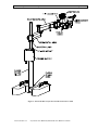
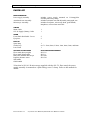
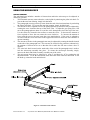
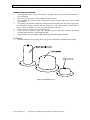
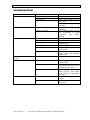
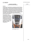
SCAN OPTICS
SO-161-R
MICROSCOPE
USER MANUAL
SO-161-R Ophthalmic Microscope
User Manual
Page 2 of 18
CONTENTS
CONTENTS_____________________________________________________________ 2
LIST OF FIGURES _______________________________________________________ 2
INTRODUCTION ________________________________________________________ 3
INTRODUCTION ________________________________________________________ 3
PARTS LIST ____________________________________________________________ 5
ASSEMBLY INSTRUCTIONS _______________________________________________ 6
TABLE MOUNTING ___________________________________________________ 6
MOUNTING TO THE SO-331 FLOOR STAND______________________________ 7
BATTERY CONNECTION, OPERATION, MAINTENANCE AND SAFETY _____ 9
USING THE MICROSCOPE ______________________________________________ 10
ARTICULATED ARM _________________________________________________ 10
POSITIONING THE MICROSCOPE______________________________________ 11
POWER SUPPLY CONTROLS __________________________________________ 11
LAMP REPLACEMENT _______________________________________________ 12
STERILISATION AND CLEANING______________________________________ 13
CARE OF THE OPTICAL HEAD ________________________________________ 14
ADJUSTING FOCUS FRICTION ________________________________________ 15
MOULD PELLET REPLACEMENT ______________________________________ 15
SPECIFICATIONS ______________________________________________________ 17
LIST OF FIGURES
Figure 1: SO-161-R Microscope
Figure 2: SO-161-R Microscope shown with SO-331 Floor stand
Figure 3: Assembling the SO-161-R Microscope
Figure 4: Assembling the SO-161-R Microscope on SO-331 Floor stand
Figure 5: SO-161-R Power supply bottom panel
Figure 6: Articulated arm features
Figure 7: SO-161-R Power supply top panel
Figure 8: Changing the lamp
Figure 9: Sterilisable covers
Figure 10: Replacing the mould pellet
Issue number 1.0
X:\Current User Manuals\SO-161-R User Manual v1.0.doc
3
4
7
8
9
10
11
12
13
15
SO-161-R Ophthalmic Microscope
User Manual
Page 3 of 18
INTRODUCTION
Please read the following information carefully before installing and using the Scan Optics SO161-R Ophthalmic microscope. Scan Optics is responsible for the safety, reliability and
performance of the equipment only if it is used in accordance with these instructions.
This microscope is designed for use by a certified practitioner, for magnified observation of
patients, and for use in an operating theatre as an observation aid during surgery. Environmental
storage and packing conditions of 60-95% relative humidity and 10-40 °C, are recommended for
this product.
No parts or accessories supplied with this microscope are supplied in a sterile condition.
Apart from those instructions within this manual, there are no user-serviceable parts in this
microscope. Scan Optics will retain the discretion to advise whether any repairs may be taken out
by external qualified technical personnel, or whether part(s) of the microscope must be returned to
the manufacturer’s premises for service or repairs to be carried out under warranty or otherwise.
Where appropriately qualified technical personnel are identified by a user, and ratified by Scan
Optics, then Scan Optics will make available on request any information that will assist in
repairing the equipment.
Figure 1: SO-161-R Microscope
Issue number 1.0
X:\Current User Manuals\SO-161-R User Manual v1.0.doc
SO-161-R Ophthalmic Microscope
User Manual
Figure 2: SO-161-R Microscope shown with SO-331 Floor stand
Issue number 1.0
X:\Current User Manuals\SO-161-R User Manual v1.0.doc
Page 4 of 18
SO-161-R Ophthalmic Microscope
User Manual
Page 5 of 18
PARTS LIST
MAIN ASSEMBLIES
Power supply assembly
Articulated Arm Assembly
Microscope Assembly
includes power supply mounted on G-clamp/pillar
assembly and safety clamp
includes horizontal arm and adjustable pantograph arm
includes tilt adjuster, microscope head, guide handle,
lamphouse, universal arm and cable
CABLES
Mains Cable
12V dc Supply (Battery) Cable
1
1
OTHER
Focus Knob Sterilisable Covers
Eyepieces
2
2
TOOL KIT
Spare lamp
Socket keys
Lens Cloth
1
set 7: 1.5mm, 2mm, 2.5mm, 3mm, 4mm, 5mm, and 6mm
1
OPTIONAL ACCESSORIES
SCAN OPTICS PART NUMBER
Floor stand (heavyweight)
Floor stand (lightweight)
Binocular assistant microscope
Pupillary distance setter
Side handle
Guide handle
SO-331*
SO-311
SO-1420
SO-1510
*Note that in SO-161-R microscopes supplied with the SO-331 floor stand, the power
supply assembly is mounted on a pillar fitting, not a G-clamp. Refer to this manual for
details.
Issue number 1.0
X:\Current User Manuals\SO-161-R User Manual v1.0.doc
SO-161-R Ophthalmic Microscope
User Manual
Page 6 of 18
ASSEMBLY INSTRUCTIONS
TABLE MOUNTING
1.
2.
3.
4.
5.
6.
7.
8.
9.
10.
11.
Remove the power supply assembly from the carton, and fix it firmly to the table using the
G-clamp knob. Use hand tightening only to fix the assembly in place – use of a spanner or
pliers to tighten the screw may strip the thread or produce excessive deflection in the clamp.
Move the safety clamp up the pillar to the desired height of the fixed arm, and lock it in
place with the thumbscrew.
Remove the arm assembly from the carton and loosen the elbow lock knob to allow the
pantograph arm to rotate about the end of the fixed arm. Then place the arm on the pillar so
that it rests on the safety clamp.
Remove the head assembly from the carton and place the pin into the collet at the end of the
pantograph arm. Tighten the wrist lock knob under the collet to secure the head assembly in
place.
Connect the lamphouse cable to the socket located on the top of the power supply box.
Connect the mains cable to the IEC socket located on the under-side of the power supply
box. Use the cable-retaining clip to secure the plug in place. Connect the other end of the
mains cable to a reliable EARTHED mains power supply.
Check the setting of the voltage selector located on the under-side of the power supply box.
If necessary, change the setting to 120 or 240V as required, using a flat-head screwdriver or
coin. Severe damage to the power supply may result if this is incorrectly set.
Switch on the mains power supply at the mains socket. When the ON/OFF switch is
selected to ON, the power supply indicator on the switch will light up.
Remove the microscope eyepiece blanks from the head assembly and insert the eyepieces.
Retain the eyepiece blanks in the eyepiece packaging for when the microscope is repacked.
Do not discard the eyepiece blanks.
When focusing the microscope, look with the right eye through the right eyepiece first and
use the focus knob or foot control to bring a target into focus at the preferred magnification.
Then look through the left eyepiece with the left eye and adjust the dial to compensate for
any relative refractive error between the eyes.
Remove two focus knob covers from the bag inside the carton. Push them into position on
to the focus knobs on either side of the microscope.
CAUTION:
•
Scan Optics recommend that ALL packaging materials be retained by the user in a safe
place, in case of future transit needs.
•
All covers are intended to be sterilised before any operating procedures.
•
The mains power supply must have a protective earth conductor. If there in no earth
conductor, or if the integrity of the earth conductor arrangement is in doubt, the equipment
must be operated from a 12Vdc power source.
Issue number 1.0
X:\Current User Manuals\SO-161-R User Manual v1.0.doc
SO-161-R Ophthalmic Microscope
User Manual
Page 7 of 18
MOUNTING TO THE SO-331 FLOOR STAND
1.
2.
3.
4.
Carefully lift the floor stand base out of the carton using the handles that are fixed to the
top. The floor stand base is extremely heavy and should only ever be lifted with the
assistance of another person. Place the floor stand base on the floor. Remove the pillar from
the carton and place it in the floor stand base. Tighten the two grub screws using the 5mm
socket key found in the tool kit to fix the pillar assembly in place.
To fix the floor stand base, screw the knobs down until the stops are resting evenly on the
floor, then screw the knurled discs down on to the floor stand base to lock the stops. To
unlock the floor stand, screw the knurled discs back up, and then unscrew the knobs until
the wheels can move freely.
Place the pillar fitting/power supply assembly on the pillar and tighten the two grub screws
to fix the assembly in place.
Continue assembling the microscope from step 2 of the instructions for table mounting.
Figure 3: Assembling the SO-161-R Microscope
Issue number 1.0
X:\Current User Manuals\SO-161-R User Manual v1.0.doc
SO-161-R Ophthalmic Microscope
User Manual
Figure 4: Assembling the SO-161-R Microscope on SO-331 Floor stand
Issue number 1.0
X:\Current User Manuals\SO-161-R User Manual v1.0.doc
Page 8 of 18
SO-161-R Ophthalmic Microscope
User Manual
Page 9 of 18
Figure 5: SO-161-R Power supply bottom panel
MOUNTING TO THE SO-311 FLOOR STAND
1.
2.
3.
Assemble the floor stand according to the instructions provided with it.
Clamp the power supply assembly to the mounting plate at the top of the floor stand.
Continue assembling the microscope from step 2 of the instructions for table mounting.
CAUTION:
•
Scan Optics advise caution when using the SO-311 floor stand with this microscope. To
prevent over-balancing, use sandbags or a similar method to weigh down the floor stand
legs. Try to use the fixed arm and pantograph arm in a compact orientation to minimize the
moment arm acting on the floor stand.
BATTERY CONNECTION, OPERATION, MAINTENANCE AND SAFETY
Scan Optics recommend the use of sealed rechargeable lead-acid 12V batteries such as Scan
Optics Cat Nos. SO-251 (small, light, lower (7Ah) capacity) and SO-9210 (large, heavy, higher
(35Ah) capacity). These batteries are maintenance -free and can be operated, charged or stored in
any position without leakage.
1.
2.
If the power supply is to be connected to a 12-volt dc supply, remove the battery cable from
the carton and connect the cable to the 3-pin plug on the underside of the power supply.
Connect the red battery clip to the positive battery terminal, and the black clip to the
negative battery terminal. The power supply will not operate if the terminals are reversed
CAUTION:
•
The 12-volt supply must be direct current. The power supply will not operate with 12 volts
alternating current.
•
Do not charge these batteries in a sealed container.
•
Avoid short-circuiting batteries.
•
Old lead-acid batteries of any type must be disposed of correctly. It is recommended that
they are recycled by an appropriate establishment who recycle car batteries. Lead acid
batteries should not be disposed of with ordinary household or medical waste, as lead
poisoning or acid trauma may result.
•
Where battery backup is used, Scan Optics recommends a periodical check of the battery to
ensure it is charged and functional.
Issue number 1.0
X:\Current User Manuals\SO-161-R User Manual v1.0.doc
SO-161-R Ophthalmic Microscope
User Manual
Page 10 of 18
USING THE MICROSCOPE
ARTICULATED ARM
The articulated arm includes a number of features that enable the microscope to be adjusted in
almost any position.
1.
The horizontal arm may rotate about the vertical pillar by unlocking the pillar lock knob. To
prevent the arm from rotating, simply lock the knob.
2.
The pantograph (moving) arm may rotate about the end of the horizontal arm by unlocking
the elbow lock knob. To prevent the arm from rotating, simply lock the knob.
3.
The amount of force required to move the pantograph arm up and down may be adjusted by
rotating the screw located at the top of the elbow joint. To adjust the gas spring force, first
move the pantograph arm down to reveal the screw through the slot in the top of the arm.
Use the socket key located in the toolbox to rotate the screw. To decrease the amount of
force required to move the arm, rotate the screw clockwise. To increase the amount of
force required to move the arm, rotate the screw anticlockwise. If the screw is adjusted to
its limit, rotate the screw half a turn in the opposite direction to ensure the arm continues to
operate smoothly.
4.
The amount of friction in the pantograph arm may be adjusted by rotating the handle located
on the side of the pantograph arm. The arm may be locked in any position or alternatively,
the amount of friction can be set so that the arm is stable but will move when a force is
applied.
5.
The wrist lock knob located on the under-side of the end of the pantograph arm is used to
lock the microscope assembly into place. To release the microscope assembly, simply
unscrew the knob and lift the assembly carefully out of the collet.
6.
The microscope head may be tilted up by some 5â and down by 45â by rotating the tilt
adjustment knob. To tilt the head down, rotate the knob in the clockwise direction. To tilt
the head up, rotate the knob anticlockwise.
Figure 6: Articulated arm features
Issue number 1.0
X:\Current User Manuals\SO-161-R User Manual v1.0.doc
SO-161-R Ophthalmic Microscope
User Manual
Page 11 of 18
POSITIONING THE MICROSCOPE
Note that the equipment must be located more than 25 cm away from any medical gas system or
disinfection or degreasing system containing flammable vapour. The power supply must also be
protected from liquid splashes and spills.
1.
Set the instrument approximately in position by swinging the elbow as required.
2.
Set the focus adjustment to the midway position by rotating the focus knob appropriately.
3.
Adjust the height of the microscope by moving the arm vertically so that the work area is
approximately in focus. Tighten the pillar and elbow lock knobs.
4.
Check the eyepiece setting to ensure clear vision with each eye separately, and set the
pupillary distance. Note that the working distance is increased by rotating both eyepieces in
a clockwise direction, and reduced by rotating both eyepieces counter-clockwise.
5.
The microscope can now be swung aside ready for use with a patient.
6.
Swing the microscope over the patient
7.
Tighten the pillar lock knob until the microscope is prevented from moving freely, but is
still able to be moved when required. The friction of the arm and elbow knobs should be
adjusted so that the movement feels uniform in all directions.
8.
To swing the microscope out of the way, unlock the pillar lock knob and swing the
microscope about the vertical pillar. It will remain in focus when returned to the work area.
POWER SUPPLY CONTROLS
Switch the microscope on using the mains switch – the LED mounted in the switch will glow
when the microscope is switched on. Use the manual light intensity adjustment to obtain a suitable
setting. Note that lamp life will be extended if a lower light intensity setting is used.
Figure 7: SO-161-R Power supply top panel
Issue number 1.0
X:\Current User Manuals\SO-161-R User Manual v1.0.doc
SO-161-R Ophthalmic Microscope
User Manual
Page 12 of 18
LAMPHOUSE AND LAMP
1.
2.
The lamp house on the SO-161-R ophthalmic microscope produces a coaxial light that
provides a red fundus reflex from the back of the eye. The intensity of the light may be
controlled from the top panel of the power supply. The lamp supplied has a rated average
life of 50 hours, but the actual life of the lamp will depend on the intensity setting normally
used. The highest setting will increase light output but will reduce lamp life. Conversely,
running the lamp at the lowest setting will produce a lamp life of greater than 50 hours.
It is strongly recommended that the lamp be replaced as a routine maintenance task, to
reduce the possibility of failure during surgery.
LAMP REPLACEMENT
1.
2.
3.
Remove the toolbox from the horizontal arm by pulling it out horizontally. The spare lamp
module is located at the end of the toolbox, and may be removed by pulling out
horizontally.
Pull out the old lamp module from the side of the lamp house by gripping the rectangular
block located beneath the cable gland at the back of the lamp house. Place the replacement
module in the lamp house so that the pins engage in the sockets and ‘click’ into place.
When the old lamp has cooled down, it may be replaced by gripping the lamp holder at the
sides where the rectangular cutout is located, and pulling the lamp out. Do not attempt to
pull the lamp out by gripping the glass capsule. Push the new lamp into the socket so that
the lamp flange sits flush on the front of the locating tube. Ensure that the new lamp is free
of grease or fingerprints before replacement. Use of protective gloves during this procedure
may be useful. Any grease marks should be removed with a solvent such as methanol to
avoid reducing lamp life. This assembly is now ready for use as a new quick-change lamp
module and may be replaced in the toolbox
Figure 8: Changing the lamp
Issue number 1.0
X:\Current User Manuals\SO-161-R User Manual v1.0.doc
SO-161-R Ophthalmic Microscope
User Manual
Page 13 of 18
STERILISATION AND CLEANING
1.
2.
3.
4.
5.
6.
7.
The removable covers may be sterilised by boiling, autoclaving, chemical sterilisation or
gas sterilisation.
One set of covers can be sterilised while the other is in use.
The anodised and plated metal components can be wiped with any of the normal
disinfectants.
The plastic parts and the paintwork of the microscope assembly and the power supply may
be affected by organic solvents. Do not autoclave or wipe with organic solvents such as
ether, xylene or alcohol. To clean, use water-based solvents only.
Focus covers are used to cover focus knobs only
Zoom covers are used to cover the optional SO-1420 binocular assistant microscope
focusing knobs and SO-1510 PD adjuster knob
Guide handle covers are used for the optional guide handle and side handles
CAUTION:
•
National authorities may require the use of specific sterilisation or disinfection methods.
Figure 9: Sterilisable covers
Issue number 1.0
X:\Current User Manuals\SO-161-R User Manual v1.0.doc
SO-161-R Ophthalmic Microscope
User Manual
Page 14 of 18
CARE AND MAINTENANCE
CARE OF THE OPTICAL HEAD
1.
Cleaning the optical components.
The eyepieces should be checked for cleanliness each time the instrument is used. Surface
dust should be removed with a clean, soft brush. Fingerprints or grease may be removed
by lightly wiping with a cotton cloth or lens tissue moistened with a 70:30 mixture of
absolute alcohol (either ethanol or methanol) and ether. Do not use acetone as it may
damage the surface coating.
2.
Cleaning the plastic parts and paintwork.
Use water based cleaners only.
Do not use any organic solvent such as alcohol, ether or xylene.
3.
Protection against mould.
In hot and humid climates, it is common for mould to grow on optical surfaces. Cleaning
and repairing the damage can be expensive and inconvenient. To minimise the risk of
mould forming, do not leave the instrument without either eyepieces or eyepiece blanks
inserted and always store the optical head in a sealed bag containing silica gel desiccant.
In tropical climates, routine annual maintenance of the optical head is recommended.
4.
Do not dismantle.
With the exception of the anti-mould pellet, no parts inside the optical head of the
instrument can be serviced by the user. Attempts to dismantle the optical head or prism
cover will make any warranty void.
Issue number 1.0
X:\Current User Manuals\SO-161-R User Manual v1.0.doc
SO-161-R Ophthalmic Microscope
User Manual
Page 15 of 18
ADJUSTING FOCUS FRICTION
The focusing system should allow the microscope head to be lowered and raised smoothly and
easily, but should not allow the head to fall under its own weight. To adjust the friction, simply
hold the plain (left) focus control knob and rotate the right focus control knob (marked “tension”)
until the desired friction is achieved. To increase the friction rotate the knob clockwise, to
decrease the friction rotate the knob anti-clockwise.
MOULD PELLET REPLACEMENT
Scan Optics microscopes are fitted with mould protection which lasts for approximately 3 years,
however, this is dependent on the storage conditions and humidity of the local environment. In
extreme tropical climates, it may be necessary to change the mould protection as frequently as
every year.
A guide to when the mould protection should be changed is placed on a sticker on the front of the
microscope head. However, this is indicative only and users should be guided by their own
experience and knowledge of local conditions. As a general precaution, always store the
microscope head in a protective bag when not in use, and replace the eyepieces with the protective
eyepiece caps.
To replace the mould pellet:
1.
Loosen the grubscrews
holding the head in the
bonder arm.
2.
Lift the head out of the arm
and remove the prism
protector.
3.
Carefully
unscrew
the
objective lens, taking care
not to damage the lamp
house prism.
4.
Use
a
Philips
head
screwdriver to remove the
mould pellet. Push the end
into the hole and lever off
the surface.
5.
Place the new pellet on the
end of the screwdriver,
remove the protective cover
and fix to the same location
where the old pellet was
removed.
6.
Screw the objective lens
back on and replace the
prism protector.
7.
Replace the head in the
bonder arm ensuring that
the head is aligned to the
front of the arm and secure
by tightening the
grubscrews.
Figure 10: Replacing the mould pellet
Issue number 1.0
X:\Current User Manuals\SO-161-R User Manual v1.0.doc
SO-161-R Ophthalmic Microscope
User Manual
Page 16 of 18
TROUBLESHOOTING
SYMPTOM
CAUSE
REMEDY
No light
No lamp/failed lamp
Mains power failure
Fuse blown
Fuse repeatedly blows
Incorrect voltage setting
Replace lamp
Use battery back-up
Check and replace fuse if
necessary
Check mains voltage setting
110/220V
Check mains voltage setting
110/220V
Check mains wiring, do not
use microscope if wired
incorrectly.
Use
battery
backup
Increase intensity
Replace lamp
Clean eyepieces, prism and
objective lens
Recharge/replace battery
Replace with lamp of correct
specification
Re-centre lamphouse on
image centre (use adjusting
grubscrews)
Increase focus friction
Mains power fault
Low light level
Intensity turned down
Aged lamp
Dirty optics
Battery power low
Incorrect lamp
Lamphouse off-centre
Microscope falls under own
weight
Blurred vision
Insufficient focus friction
Dirty optics
Mouldy optics
Refractive error
Microscope unsteady
Unstable surface
Knobs loose
Issue number 1.0
Clean eyepieces, prism and
objective lens
Carefully clean mould from
optical elements and replace
mould protection pellet
Focus right eye first through
RHS eyepiece then adjust
LHS eyepiece to compensate
for error
Stiffen mounting surface with
a plate
Tighten adjustment knobs as
necessary
X:\Current User Manuals\SO-161-R User Manual v1.0.doc
SO-161-R Ophthalmic Microscope
User Manual
Page 17 of 18
SPECIFICATIONS
OPTICAL HEAD
VIEWING SYSTEM
Binocular, stereoscopic
(convergence angle 12o )
Eyepiece tube inclination 45o
MAGNIFICATION
Fixed, 6.25 x
Optional 9.4x eyepieces
WORKING DISTANCE
Lamphouse prism to object distance 165 mm
FIELD OF VIEW
44mm
REFRACTIVE ERROR
Adjustment +5o to -5o , left eyepiece
FOCUSING
Range ± 25mm
Control knobs removable for sterilisation
INTERPUPILLARY DISTANCE
Adjustable for PD range approximately 50 to 80mm
ILLUMINATION
ALIGNMENT
Coaxial with viewing system
LAMP
12V 50W quartz-halogen lamp
FILTERS
Internal ultraviolet and infrared filters
AVERAGE
LAMP LIFE
Medium intensity: 50 hours
ILLUMINATION
60,000 Lux approximately at maximum setting.
LAMP CHANGE
Plug in for fast change, no screws
POWER SUPPLY
MAINS POWER
OUTPUT
220-240V/0.2A; 110-120V/0.4A
12V 50W
INTENSITY CONTROL
Continuous
EARTHING
via earth lead on mains cable (green/yellow)
FUSE
250V/3A 20x5 mm
CABLES
Mains:
Battery:
Issue number 1.0
Length 5 metres
Length 5 metres
X:\Current User Manuals\SO-161-R User Manual v1.0.doc
SO-161-R Ophthalmic Microscope
User Manual
Page 18 of 18
MOUNTING SYSTEM
HEAD TILT
+5â to -45â
VERTICAL TENSION
Adjustable gas spring to set lifting force
DIMENSIONS
Vertical pillar to head optical axis
max 840 mm (33")
Pantograph arm vertical range 320 mm (13")
MATERIALS
No ferrous metals to rust or corrode
Issue number 1.0
X:\Current User Manuals\SO-161-R User Manual v1.0.doc