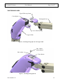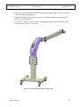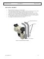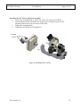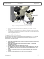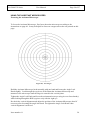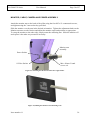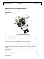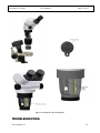
1
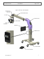
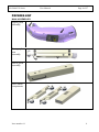
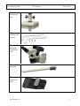
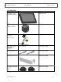
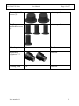
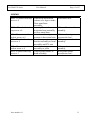
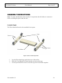
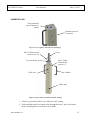
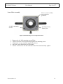
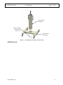
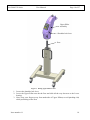
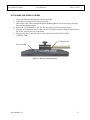
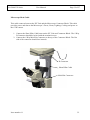
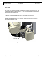
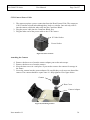
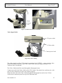
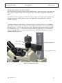
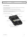
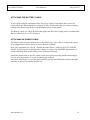
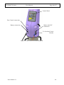
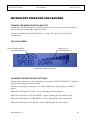
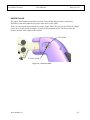
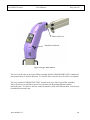
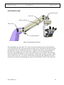
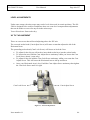
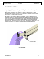
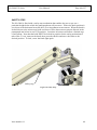
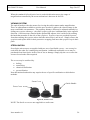
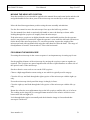
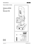
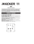
SO-5800
Oph
Ophthalmic Microscope
USER MANUAL
SCAN OPTICS
SO-5800
MICROSCOPE
ASSEMBLY
AND OPERATOR’S
MANUAL
Issue number 1.0
SO-5800 XY Series
User Manual
Page 3 of 57
CONTENTS
INTRODUCTION.................................................................................................................................................... 6
PACKING LIST ...................................................................................................................................................... 8
MAIN ASSEMBLIES ....................................................................................................................................... 8
CABLES .......................................................................................................................................................... 10
ACCESSORIES............................................................................................................................................... 11
SCREWS ......................................................................................................................................................... 13
ASSEMBLY INSTRUCTIONS ............................................................................................................................. 14
FLOOR STAND .............................................................................................................................................. 14
LOWER PILLAR ............................................................................................................................................ 15
Lower Pillar Assembly ................................................................................................................................ 16
UPPER PILLAR .............................................................................................................................................. 17
PANTOGRAPH ARM..................................................................................................................................... 19
HEAD AND XY ASSEMBLY ........................................................................................................................ 21
Attaching the XY Unit to the Head Assembly.............................................................................................. 22
ATTACHING THE GUIDE HANDLES......................................................................................................... 25
ASSISTANT MICROSCOPE ASSEMBLY.................................................................................................... 26
Swapping from R/H to L/H configuration................................................................................................... 27
USING THE ASSISTANT MICROSCOPES.................................................................................................. 28
Focussing the Assistant Microscope ........................................................................................................... 28
MONITOR, CABLE, CAMERA AND POWER ASSEMBLY....................................................................... 30
ATTACHING THE VIDEO SYSTEM............................................................................................................ 31
Microscope Head Cable ............................................................................................................................. 32
Zoom Cable................................................................................................................................................. 33
CCD Camera Power Cable......................................................................................................................... 34
Attaching the Camera ................................................................................................................................. 34
Video Signal Cable ..................................................................................................................................... 35
Setting the position for the Video Camera .................................................................................................. 36
FOOT CONTROL UNIT................................................................................................................................. 38
ATTACHING THE BATTERY CABLE ........................................................................................................ 39
ATTACHING HE POWER CABLE ............................................................................................................... 39
MICROSCOPE OPERATION AND FEATURES ............................................................................................. 41
TURNING THE MICROSCOPE ON AND OFF ............................................................................................ 41
THE LCD SCREEN......................................................................................................................................... 41
CHANGING THE MICROSCOPE SETTINGS.............................................................................................. 41
XY RETURN TO CENTRE (RTC) ................................................................................................................. 42
UPPER PILLAR .............................................................................................................................................. 42
PANTOGRAPH ARM..................................................................................................................................... 42
LEVEL ADJUSTMENTS ............................................................................................................................... 42
XY TILT ADJUSTMENT ............................................................................................................................... 42
GAS SPRING ADJUSTMENT ....................................................................................................................... 42
SAFETY STOP................................................................................................................................................ 42
POWER SYSTEM........................................................................................................................................... 42
LIGHTING SYSTEM...................................................................................................................................... 42
FOCUS MECHANISM ................................................................................................................................... 42
ZOOM MECHANISM .................................................................................................................................... 42
VIEWING SYSTEM ....................................................................................................................................... 42
STERILISATION............................................................................................................................................ 42
MOVING THE HEAD INTO POSITION ....................................................................................................... 42
FOCUSSING THE MICROSCOPE ................................................................................................................ 42
MONITOR AND CAMERA SYSTEM........................................................................................................... 42
ASSISTANT MICROSCOPE.......................................................................................................................... 42
FOOT CONTROL ........................................................................................................................................... 42
Issue number 1.1
3
SO-5800 XY Series
User Manual
Page 4 of 57
ROUTINE CARE AND MAINTENANCE ............................................................................................................. 42
OPTICAL HEAD ................................................................................................................................................. 42
Cleaning the optical components................................................................................................................ 42
Cleaning the plastic parts and paintwork ................................................................................................... 42
Protection against mould ............................................................................................................................ 42
REPLACING MOULD PROTECTION ...................................................................................................................... 42
TROUBLESHOOTING ......................................................................................................................................... 42
SYMPTOM .................................................................................................................................................. 42
FIRST STEP ................................................................................................................................................ 42
REMEDY..................................................................................................................................................... 42
SPECIFICATIONS ............................................................................................................................................... 42
Table of figures
Figure 1, Microscope - main components ................................................................................. 7
Figure 2, Floor stand components............................................................................................ 14
Figure 3, Lower pillar, removed from packaging .................................................................... 15
Figure 4, Lower pillar assembly and cable routing. ................................................................ 15
Figure 5, Detail showing screw arrangement on Post ............................................................. 16
Figure 6, Assembling Lower pillar onto Floorstand............................................................... 17
Figure 7, Fitting Upper Pillar to Post...................................................................................... 18
Figure 8, Postioning Pantograph Arm onto Upper Pillar........................................................ 19
Figure 9, Attaching Pantograph arm....................................................................................... 19
Figure 10, Pantograph asembled onto Upper Pillar................................................................. 20
Figure 11: Suspension Bracket Assembly ............................................................................... 21
Figure 12, attaching head to XY unit....................................................................................... 22
Figure 13, aligning XY unit onto Pantograph arm. ................................................................ 23
Figure 14, XY unit located on Pantograph arm. ..................................................................... 23
Figure 15, fitting eyepieces...................................................................................................... 24
Figure 16, fitting Guide handle................................................................................................ 25
Figure 17, Assistant microscope components.......................................................................... 26
Figure 18, Assistant microscope assembled. ........................................................................... 26
Figure 19: Attaching Assistant Microscope to Main Assembly .............................................. 27
Figure 20, Test Target............................................................................................................. 28
Figure 21, attaching the Monitor bracket onto Upper Pillar.................................................... 30
Issue number 1.1
4
SO-5800 XY Series
User Manual
Page 5 of 57
Figure 22, Sliding the Monitor onto Mounting Arm. .............................................................. 30
Figure 23, Monitor Connection Panel...................................................................................... 31
Figure 24, Zoom cable connection. ......................................................................................... 33
Figure 25, Watec Camera ........................................................................................................ 34
Figure 26, Mounting Camera................................................................................................... 34
Figure 27, Head Control Unit, connections ............................................................................. 35
Figure 28, Camera cabling....................................................................................................... 35
Figure 29, setting Camera focus .............................................................................................. 36
Figure 30, Foot Control Unit layout. ....................................................................................... 38
Figure 31, Control Panel and connection panels. .................................................................... 40
Figure 32, LCD screen, close-up ............................................................................................. 41
Figure 33, XY Control Unit ..................................................................................................... 42
Figure 34, Connection panel ................................................................................................... 42
Figure 35, Upper Pillar features............................................................................................... 42
Figure 36, Pantograph Arm features........................................................................................ 42
Figure 37, XY level adjustment. .............................................................................................. 42
Figure 38, Gas Spring. ............................................................................................................. 42
Figure 39, Safety Stop. ............................................................................................................ 42
Figure 40, Sterile Covers ......................................................................................................... 42
Figure 41, Microscope Head -Underside view ........................................................................ 42
Figure 42, Fitting the Anti-mould pellet.................................................................................. 42
Issue number 1.1
5
SO-5800 XY Series
User Manual
Page 6 of 57
INTRODUCTION
Please read this manual carefully before installing and using the Scan Optics
SO-5800 Ophthalmic microscope. Scan Optics is responsible for the safety,
reliability and performance of the equipment only if it is used in accordance
with these instructions.
This microscope is designed for use by a certified practitioner, for magnified
observation of patients, and for use in an operating theatre as an observation aid
during surgery.
Environmental storage and packing conditions of 60-95% relative humidity and
10-40 °C, are recommended for this product.
No parts or accessories supplied with this microscope are supplied in a sterile
condition.
The only user-serviceable parts in this device are identified in this manual.
Contact Scan Optics if any other parts fail.
Scan Optics
32 Stirling Street
Thebarton SA 5031
AUSTRALIA
Tel
Fax
Email
+61 8 8234 9120
+61 8 8234 9417
[email protected]
Priory Analysts Ltd
PO Box 4030
Milton Keynes
MK13 0ZG
UNITED KINGDOM
Issue number 1.1
6
SO-5800 XY Series
User Manual
Page 7 of 57
Figure 1, Microscope - main components
SUSPENSION
BRACKET
PANTOGRAPH ARM
X-Y UNIT
UPPER PILLAR
LAMPHOUSE
HEAD
ASSEMBLY
MONITOR
LOWER PILLAR
Foot Control
Storage on peg
FLOOR STAND
FOOT CONTROL
Issue number 1.1
7
SO-5800 XY Series
User Manual
Page 8 of 57
PACKING LIST
MAIN ASSEMBLIES
Upper pillar
assembly
Pantograph
arm
assembly
Lower pillar
assembly
Floor stand
components
Issue number 1.1
8
SO-5800 XY Series
User Manual
Page 9 of 57
XY unit
(packed in
box)
Suspension
bracket and
spacers
Head
assembly
(packed in
box)
Monitor arm
assembly
Foot control
(packed in
box)
Issue number 1.1
9
SO-5800 XY Series
User Manual
Page 10 of 57
CABLES
CABLE TYPE
Microscope
power cable
Mains cable
APPLICATION
Connects between horizontal arm
socket and XY unit
Connects mains power supply to
IEC socket at pillar base
Video cable
Connects between video camera
and monitor
Camera power
Connects between XY unit and
cable
camera power input
Monitor power
Connects between pillar and
cable
monitor power input
Foot control
Connects foot control to
cable
connector at pillar base
Head power cable Connects head assembly to head
power socket on XY unit
Issue number 1.1
PACKED LOCATION
Pantograph arm
Accessories box
Pantograph arm
Monitor box
Monitor box
Hard-wired to foot
control
Hard-wired to head
assembly
10
SO-5800 XY Series
User Manual
Page 11 of 57
ACCESSORIES
ITEM
DEPICTION
PACKED LOCATION
Monitor (with
attached adapter)
Monitor box
Video camera
(Watec 221S)
Monitor box
Binocular
assistant
microscope
microscope box
Assembly and
Operator’s
manual
Side handles x 2
This manual
microscope box
microscope box
Microscope cover
microscope box
Zoom sterilisable
covers
(2)
microscope box
Issue number 1.1
11
SO-5800 XY Series
User Manual
Page 12 of 57
Focus sterilisable
covers (2)
microscope box
Handle
sterilisable covers
(6)
microscope box
Allen key set
N/A
Adjustable
eyepieces X 2
Cleaning cloth
Issue number 1.1
Tool box
Tool box
N/A
Tool box
12
SO-5800 XY Series
User Manual
Page 13 of 57
SCREWS
SIZE/NUMBER
APPLICATION
PACKED LOCATION
M8 x 70 socket head cap
screw x 4
Attach top and bottom
joiners over legs to make
floor stand base
assembly
Attach pillar and
horizontal arm assembly
to floor stand base
Attach arm bearing
mounts to horizontal arm
Attach suspension
bracket assembly to head
assembly and XY unit
Attach monitor arm
assembly to pillar
Attach guide handle to
head assembly
Accessories box
M10 x 25 socket head
cap screw x 4
M6 x 20 countersunk
socket screws x 8
M6 x 30 socket head cap
screws x 8
M5 x 12 countersunk
socket screw x 4
M5 x 8 socket head cap
screw x 1
Issue number 1.1
Pillar and horizontal arm
assembly
With arm bearing mounts
(accessories box)
With suspension bracket
assembly
With monitor arm
assembly
With guide handle
(accessories box)
13
SO-5800 XY Series
User Manual
Page 14 of 57
ASSEMBLY INSTRUCTIONS
Note: To ensure all functions work correctly it is important that all cables are connected
before switching the power onto the unit.
FLOOR STAND
The Floor Stand will need to be assembled in two parts.
Legs
Screws
Screw
Cross Beam
Figure 2, Floor stand components
1.
2.
3.
Lay the Floor Stand legs upside down on a flat surface.
Place the Cross Beam face down into the cut-outs on the legs.
Use the provided M10 screws to lock the legs and Cross Beams together.
Issue number 1.1
14
SO-5800 XY Series
User Manual
Page 15 of 57
LOWER PILLAR
Post-postioned
up-side down for
transit
Handle removed
for transit
Figure 3, Lower pillar, removed from packaging
M10 x 30mm socket
head screws x 4
Lower bearing
Post
M8 x 30mm
socket head
screws x 2
Handle
Cable exit
Cable entry
Figure 4, Lower pillar assembly and cable routing.
1. 2 holes are provided in the Lower Pillar for cable routing.
2. Feed the Mains and Foot control cable through the holes , this is best done
before attaching the Post onto the Lower Pillar.
Issue number 1.1
15
SO-5800 XY Series
User Manual
Lower Pillar Assembly
4 x M10 mounting
screws
Page 16 of 57
Note, 1 screw is offset,
post postion is
polarized.
Leveling screwsFactory set.
Figure 5, Detail showing screw arrangement on Post
1. Remove the 4 x M10 mounting screws Pillar.
2. Place Post in the correct postion and replace the mounting screw.
3. Tighten the screws using the supplied hex driver.
4. Place the Lower Pillar into the Floorstand.
5. Insert 4 x M10 screw into the underside of the Floorstand and fully tighten.
Issue number 1.1
16
SO-5800 XY Series
User Manual
Page 17 of 57
Lower pillar
assembly
M10 x 40mm
Socket head
screws x 4
Floor stand
assembly
Figure 6, Assembling Lower pillar onto Floorstand
UPPER PILLAR
Issue number 1.1
17
SO-5800 XY Series
User Manual
Page 18 of 57
Upper Pillar
assembly
Shoulder lock lever
Post
Figure 7, Fitting Upper Pillar to Post
1. Loosen the shoulder lock lever.
2. Lower the Upper Pillar onto the the Post and slide all the way down on to the Lower
bearing.
3. Note, keep your fingers away from underside of Upper Pillar(to avoid pinching risk)
while postioning on the Post
Issue number 1.1
18
SO-5800 XY Series
User Manual
Page 19 of 57
PANTOGRAPH ARM
Upper Pillar top clamp
Cam adjuster
Pantograph Arm
Lower Shaft bearing
Upper Pillar
Figure 8, Postioning Pantograph Arm onto Upper Pillar
M8 x 30mm
Socket heaad
M8 washer
Cam adjuster
Figure 9, Attaching Pantograph arm
Issue number 1.1
19
SO-5800 XY Series
User Manual
Page 20 of 57
1. Postion the Upper Pillar top clamp onto the Pantograph arm shaft. Lock the top clamp
in line with the Pantograph arm.
2. Align the Pantograph arm shaft over the lower shaft bearing and Cam adjuster and
gently lower into postion.
3. Lock the top clamp in postion and check Pantograph arm for smooth rotation adjust
cam if necessary and re lock screws.
Figure 10, Pantograph asembled onto Upper Pillar
Issue number 1.1
20
SO-5800 XY Series
User Manual
Page 21 of 57
HEAD AND XY ASSEMBLY
1.
2.
3.
4.
5.
Place the Head Assembly on a clean flat table.
Attach the Suspension Brackets to Tilt Adapter (as shown in the picture below) with
the 4 x M6x16 Button Head. Tighten, then loosen the screw by 1 turn.
Locate the XY Unit to the top of the Suspension Bracket and also lock it with the
supplied 4 x M6x16 Button Head. Do not tighten fully (loosen the screw by 1 turn)
Place the Spacer part between the Suspension Brackets and secure with the supplied
2 x M6x16 Button Head from both sides and tighten the screw.
Now tighten all 8 Button Head screws securely.
Suspension Brackets
Screws
Tilt Adapter
Figure 11: Suspension Bracket Assembly
Issue number 1.1
21
SO-5800 XY Series
User Manual
Page 22 of 57
Attaching the XY Unit to the Head Assembly
1. Loosen the Locking Knob on either side of the XY Upper Swivel Block.
2. Lift the Head and XY Assembly (two people may be required) up to the XY
Mounting Plates and let it sit securely in the slots.
3. Tighten the Locking Knob.
4. Tighten the XY Rotation Locking Knob.
Locking
Knobs
Figure 12, attaching head to XY unit
Issue number 1.1
22
SO-5800 XY Series
User Manual
Page 23 of 57
Figure 13, aligning XY unit onto Pantograph arm.
Figure 14, XY unit located on Pantograph arm.
Issue number 1.1
23
SO-5800 XY Series
User Manual
Page 24 of 57
Remove the eyepiece blanks and insert the eyepieces. Insert the focusing eyepiece in the
LHS eyepiece tube from the observer’s perspective and secure in place so that the scale
marker is easily visible. Place the fixed eyepiece in the RHS eyepiece tube and secure using
the screw. Retain the eyepiece caps in a safe place for when storing the microscope.
PD adjuster
Securing screws
Focusing eyepieces
Eyepiece blanks
Figure 15, fitting eyepieces
Issue number 1.1
24
SO-5800 XY Series
User Manual
Page 25 of 57
ATTACHING THE GUIDE HANDLES
Insert the guide handles into the side of the microscope.
Note that the Groove and the Grub Screw Dimple on the handle needs to face upwards.
Lock down the handle by tightening the Grub Screw with the 4mm Hex Driver.
Locking Grub Screw
Grove on Guide Handle
Grub Screw Dimple
Figure 16, fitting Guide handle.
Issue number 1.1
25
SO-5800 XY Series
User Manual
Page 26 of 57
ASSISTANT MICROSCOPE ASSEMBLY
Focus Knob
Microscope Lock Knob
Angle Lock screw
Microscope Mount
Mounting Arm Lock
Screw
Mounting Arm
Figure 17, Assistant microscope components.
Figure 18, Assistant microscope assembled.
1.
2.
3.
4.
Remove the Mounting Arm Lock Screw from the Microscope Mount.
Slide the Microscope Mount onto the Mounting Arm.
Lock the Mounting Arm Lock Screw tightly with the 5mm Hex Driver.
Position the Assistant Microscope to the Microscope Mount, then secure by locking
the Microscope Lock Knob into the Threaded Hole.
Issue number 1.1
26
SO-5800 XY Series
User Manual
Page 27 of 57
Assembled Assistant
Microscope
Accessory Mount
M8 Grub Screw
Figure 19: Attaching Assistant Microscope to Main Assembly
5.
6.
Insert the Assembled Assistant Microscope Mounting Arm into the Accessory
Mount.
In order to set the Assistant Microscope Mount in a horizontal position; support the
weight of the Assistant Microscope Head in one hand while you tighten the M8 Grub
Screw using the 4m Hex Driver.
Swapping from R/H to L/H configuration
The previous procedure shows the assistant microscope being attached to the R/H side of the
main microscope. However the assistant microscope can also be configured so it can be
attached to the L/H side if required.
1. Remove the Assistant Microscope Assembly from the Accessory Mount, by loosening
the M8 Grubscrew
2. Remove the Assistant Microscope from the Microscope Mount, by undoing the
Microscope Lock Knob.
3. Insert the arm into the Accessory Mount on the L/H side.
4. The mount has to be rotated 180, simply undo the Angle Lock Knob about 5mm (this
will disengage the limit travel pins) rotate the mount and re tighten the Angle Lock
Knob.
5. Re-attach the Assistant Microscope to the mount and adjust the angle for optimum
position.
6. Re-attach the short guide handle to the R/H Accessory Mount Block.
Issue number 1.1
27
SO-5800 XY Series
User Manual
Page 28 of 57
USING THE ASSISTANT MICROSCOPES
Focussing the Assistant Microscope
To focus the Assistant Microscope, first focus the main microscope according to the
instructions on page 49. It may be helpful to focus on a target such as the one printed on this
page.
Figure 20, Test Target.
Hold the Assistant Microscope head assembly with one hand and loosen the Angle Lock
Knob slightly. Look through the eyepieces of the Binocular Assistant Microscope and
manoeuvre the microscope until the target is centred in the vertical plane.
Tighten the Angle Lock Knob and focus the assistant microscope using its own focus knob(s)
while looking through the RHS eyepiece only with the right eye.
Re-check the vertical alignment and adjust the position of the Assistant Microscope head if
necessary after loosening the angle lock knob. Re-tighten the Angle Lock Knob when
vertical alignment is achieved.
Issue number 1.1
28
SO-5800 XY Series
User Manual
Page 29 of 57
Look through the LHS (adjustable) eyepiece with the left eye and rotate the collar until the
left eye is in focus. Housings are not geared together and need to be adjusted to a symmetrical
position manually.
When this procedure is complete the microscope should be centred on the vertical plane of
the target and focussed on the centre of the target, although there may be some left-right
displacement.
To correct for left-right displacement, loosen the microscope lock knob and swivel the
microscope head assembly left or right slightly until the centre of the target is in the centre of
the view. Tighten the microscope lock knob to secure the assembly.
The assistant microscope should stay focussed so long as the image through the main
microscope is focussed.
Adjust the pupillary distance (PD) of the assistant microscope to a comfortable setting by
rotating the prism housings apart or together as required.
Issue number 1.1
29
SO-5800 XY Series
User Manual
Page 30 of 57
MONITOR, CABLE, CAMERA AND POWER ASSEMBLY
Attach the monitor arm to the back of the pillar using the four M5 x 12 countersunk screws,
and tighten using the 3 mm socket key provided.
Slide the monitor over the arm in the desired orientation. Tighten the adjustment knob on the
Monitor mount to set the friction and adjust the monitor angle and position as appropriate.
To swap the monitor to the other side, simply rotate the mounting arm. Slide the monitor off
and replace it the other way around if necessary.
Monitor arm
assembly
Power Socket
S-Video Socket
M6 x 20mm C/sunk
screws x 4
Figure 21, attaching the Monitor bracket onto Upper Pillar.
Figure 22, Sliding the Monitor onto Mounting Arm.
Issue number 1.1
30
SO-5800 XY Series
User Manual
Page 31 of 57
ATTACHING THE VIDEO SYSTEM
1. Lower the Monitor Mounting Arm onto the Pillar.
2. Tighten the Locking Knob so that it is stable.
3. Thread the video cable through the Pillar Mounting Block, up the arm and exit at the
Monitor Mounting Adapter.
4. Rotate the LCD Monitor so it is flat for easy access to the connection panel.
5. Plug the LCD Monitor Power Cable into the LCD Power Socket. Plug the other end of
the power cable to the top of the Pillar.
6. Plug the S-Video Cable into the S-Video Input socket. DO NOT FORCE
CONNECTOR.
S-Video Socket
Power Socket
Figure 23, Monitor Connection Panel.
Issue number 1.1
31
SO-5800 XY Series
User Manual
Page 32 of 57
Microscope Head Cable
This cable connects between the XY Unit and the Microscope Connector Block. This cable
provides power and data to the Microscope’s Focus, Zoom, Lighting, Cooling and power to
the CCD camera.
1. Connect the Short Pillar Cable between the XY Unit and Connector Block. The 9 Way
D Connector should be locked with the terminal screws.
2. Connect the 8 Way Mini Din Connector to the top of the Connector Block. The flat
side of the connector should face inwards.
D-Connector
Short Pillar Cable
Mini-Din Connector
Issue number 1.1
32
SO-5800 XY Series
User Manual
Page 33 of 57
Zoom Cable
The Zoom Cable connects between the Zoom Drive and Connector Block. In most cases, this
cable should be already connected, however, in some setups, this cable may be supplied loose
and should be connected before use.
Connect the zoom cable from the Zoom Drive Control to the Connector Block.
Note that this plug needs to be FULLY inserted to function correctly. Push the connector
down until a solid click is heard.
Zoom Cable
Figure 24, Zoom cable connection.
Issue number 1.1
33
SO-5800 XY Series
User Manual
Page 34 of 57
CCD Camera Power Cable
1. The camera requires a power connection from the Head Control Unit. The connector
is NOT similar on both ends although they look very similar. One end only will fit
into the camera, whilst the other only into the Connector Block.
2. Plug the power cable into the Connector Block first.
3. Plug the other end of the power cable to the CCD Camera.
S-Video Socket
Power Socket
Figure 25, Watec Camera
Attaching the Camera
4. Remove the dust cover from the camera adapter part on the microscope.
5. Remove the dust cover from the camera.
6. Keep the dust covers in a safe place if you need to remove the camera for storage in
the future.
7. Screw the camera into the camera adapter. Be careful that you do not cross thread the
camera. The camera should be square once it’s fully tightened. See figure below
Camera
Dust Cover
Camera Adapter
Figure 26, Mounting Camera.
Issue number 1.1
34
SO-5800 XY Series
User Manual
Page 35 of 57
Head
Control
Unit
Figure 27, Head Control Unit, connections
Video Signal Cable
XY power cable
S-Video cable
Camera power lead
Figure 28, Camera cabling
The video signal out of the CCD camera is transmitted via S-VIDEO – a more superior video
transmission than Composite video. The Video Cable carries the signal from the CCD
Camera to the LCD monitor.
The Video Cable should be routed through the Pantograph Arms.
Connect one end of the Video Cable to the CCD Camera. Note that it has a polarity pin, so do
not force the connection if it does not connect properly.
Route the other end of the Video Cable through the Pantograph Arm and to the S-Video
socket in the connection panel on top of the Horzontal arm
Issue number 1.1
35
SO-5800 XY Series
User Manual
Page 36 of 57
Setting the position for the Video Camera
Focus the main microscope at the preferred magnification. If the microscope is typically used
with a range of magnifications, focus the microscope at the highest magnification (smallest
field).
Loosen the two lower grubscrews below the camera. Observe the image on the monitor, and
focus the camera by rotating the lower ring. Re-tighten the lower grubscrews when the
camera is focussed.
Check the orientation of the image by moving an object across the field, to see if left/right
and up/down on the monitor correspond with left/right and up/down as observed through the
main microscope. If it does not, loosen the upper grubscrew and rotate the upper ring until
the orientation is correct. This should correspond with the upside-down ‘CE’ mark on the
camera facing the observer using the main microscope. When the orientation is correct, retighten the upper grubscrew.
Upper ring
Upper grubscrew
Lower ring
Lower grubscrews X2
Figure 29, setting Camera focus
Issue number 1.1
36
SO-5800 XY Series
User Manual
Page 37 of 57
The video system should now be ready for use.Scan Optics recommend that the original
(default) settings on the Watec camera be used.
These are as follows:
SHUTTER SPEED
POSITION 8 (EI OFF)
AGC
ON
AGC
HI
VIDEO LEVEL
100
GAMMA
ON
WHITE BALANCE
AUTO
BACK LIGHT
OFF
Refer to the Watec leaflet enclosed with the camera for further information regarding shutter
speeds and white balance.
Issue number 1.1
37
SO-5800 XY Series
User Manual
Page 38 of 57
FOOT CONTROL UNIT
The Foot Control Unit controls some of the settings on the Microscope that the operator may
wish to change during surgery.
It primarily controls the Focus, Zoom, Light intensity and XY movement.
To activate any of the functions, the operator should depress the pedals firmly.
The XY Translation Control Stick controls the XY movement of the head. Push the stick in
the direction you want the FIELD OF VIEW to move.
XY Translation Control Stick
Light Up
Light Down
Focus Up
Zoom In
Focus Down
Zoom Out
Figure 30, Foot Control Unit layout.
Issue number 1.1
38
SO-5800 XY Series
User Manual
Page 39 of 57
ATTACHING THE BATTERY CABLE
If you will be using the equipment where the power supply is unreliable and you are not
connected to an Uninterrupted Power Supply (UPS), it’s advisable that you connect a battery
backup to the microscope in the event that mains power is unavailable.
The Battery Cable is a 9 Way D Socket that plugs into the Power Supply and is recommended
that you connect it to a 12V Car Battery.
ATTACHING HE POWER CABLE
The Mains Cable provides mains power to the Microscope. This cable is orange and requires
to be plugged into a source where an active Earth is available.
Note: The equipment is a Class II – Double Insulated Device, with NO ACTIVE EARTH
POINT. For the internal switching power supply to comply with EMF/RFI requirements, it
requires an Earth Point on the mains power to function correctly.
Attach the mains cable to the IEC socket on the lower panel and plug into the mains supply.
Use the wire plug retainer to avoid accidental plug removal.
Switch the microscope on from the main panel by pressing the RED button, and set the light
intensity as desired. Switch the monitor on.
Issue number 1.1
39
SO-5800 XY Series
User Manual
Page 40 of 57
Control Panel
Foot Control connection
Battery connection
Mains cable IEC
connection
5A Overload Circuit
Breaker
Figure 31, Control Panel and connection panels.
Issue number 1.1
40
SO-5800 XY Series
User Manual
Page 41 of 57
MICROSCOPE OPERATION AND FEATURES
TURNING THE MICROSCOPE ON AND OFF
Hold the red ON/OFF button for 1 second to turn it on. The microscope will go through it’s
start up and power up normally within 2 seconds.
To turn off, hold the red ON/OFF button for 1 second. The microscope will turn off
automatically.
THE LCD SCREEN
Setting Level
(black buttons < >)
Current Function Mode
select(Blue button)
Figure 32, LCD screen, close-up
CHANGING THE MICROSCOPE SETTINGS
Settings on the microscope can be changed by pressing the “FUNCTION SELECT” button to
toggle to the settings you want to adjust.
Increase the setting by pressing the “UP” button and decrease by pressing the “DOWN”
button.
When the LCD displays “LIGHT”, you are adjusting the LED intensity.
When the LCD displays “FOCUS SPEED”, you are adjusting the focus motor speed.
When the LCD displays “ZOOM SPEED”, you are adjusting the zoom motor speed.
When the LCD displays “XY SPEED”, you are adjusting the XY motor speed.
Issue number 1.1
41
SO-5800 XY Series
User Manual
Page 42 of 57
XY RETURN TO CENTRE (RTC)
RTC Sensor
Figure 33, XY Control Unit
To activate the XY Return to Centre, there are two ways to do this.
Through the Power Supply:
Press the “FUNCTION SELECT” button until the text “XY RTC?” is displayed.To activate,
press the “OK” to return the XY back to the centre.
Through the XY Unit:
Hold your hand/finger approximately 25mm (1 inch) in front of the XY Unit Label for 1
second.
Once detected, you will hear a short beep and the XY will automatically return to the centre.
Issue number 1.1
42
SO-5800 XY Series
User Manual
Page 43 of 57
UPPER PILLAR
The upper Pillar rotates around the top of the Lower Pillar and provides a connection
interface for the main microscope power cable and s-video cable.
There are two sockets located at the top of the Upper Pillar. The top one provides low voltage
power for XY unit and focus motors, as well as the lamp and its fan. The lower mini din
socket connects video signal to the camera
XY socket
S Video socket
Figure 34, Connection panel
Issue number 1.1
43
SO-5800 XY Series
User Manual
Page 44 of 57
Elbow lock lever
Shoulder lock knob
Figure 35, Upper Pillar features.
The lever on the side of the Upper Pillar assembly labelled ‘SHOULDER LOCK’ enables the
horizontal arm to be fixed in position. To lock the arm, rotate the lever in clock-wise fashion.
The lever marked ‘ELBOW FRICTION’ located at the top of the Upper Pillar assembly
allows friction to be applied to the swivel joint between the pantograph arm and the
horizontal arm. To increase friction, rotate the knob in clock-wise fashion when viewed from
beneath the horizontal arm.
Issue number 1.1
44
SO-5800 XY Series
User Manual
Page 45 of 57
PANTOGRAPH ARM
Rotation lock
Arm lock
Safety set knob
Elbow lock
Gas spring adjuster
Figure 36, Pantograph Arm features.
The pantograph can rotate some 270° relative to the horizontal arm and is locked using the
Lever located on the side of the horizontal arm (Elbow lock). Note that if both elbow friction
and shoulder locks are applied and a side force is applied to the end of the pantograph arm,
the elbow lock will give way if sufficient force is applied. If a fixed angle between the
horizontal and pantograph arm is required, the elbow friction will work best if the shoulder
lock is not applied. To lock the arm in a particular vertical position, simply rotate the ‘ARM
LOCK’ knob clock-wise. To lock the rotational movement of the XY unit and microscope
head below the end of the pantograph arm, rotate the ‘ROTATION LOCK’ knob clock-wise.
Issue number 1.1
45
SO-5800 XY Series
User Manual
Page 46 of 57
LEVEL ADJUSTMENTS
Under some setups, the microscope may not be level when used in certain positions. The SO5800 is designed to be used level and hence there are some level compensations adjustments
that can be made to correct for any tilt in the microscope.
You will need two 5mm socket key.
XY TILT ADJUSTMENT
There are two screws that will need adjusting above the XY unit.
The recessed socket head (Cam Adjust Screw) will rotate a cam that adjusts the tilt of the
Horizontal Arm.
The protruding socket head (Cam Lock Screw) will loosen or lock the Cam.
•
•
•
•
To adjust for the tilt you will need to insert both socket keys into the socket heads.
To loosen the cam, hold the Cam Adjust Screw stationary whilst you loosen the Cam
Lock Screw (about ¼ turn only)
To adjust for the tilt, hold the Cam Lock Screw stationary whilst your rotate the Cam
Adjust Screw. This will cause the Horizontal Arm to tilt up and down.
Once your Horizontal Arm is level, hold the Cam Adjust Screw stationary then tighten
the Cam Lock Screw until it’s tight.
Cam Lock Screw
Cam Adjust Screw
Figure 37, XY level adjustment.
Issue number 1.1
46
SO-5800 XY Series
User Manual
Page 47 of 57
GAS SPRING ADJUSTMENT
A gas spring inside the pantograph arm provides lifting force, which is able to support the
weight of the XY unit and microscope head at the end of the arm.
By moving the end position of the gas spring, the amount of lifting force can be varied
depending on the preference of the user or to suit the weight of additional accessories which
may be placed on the microscope head assembly.
By rotating the knob clockwise, the end of the gas spring is lowered which increases the
amount of vertical force. Similarly, anticlockwise movement will increase the end position
height and reduce the amount of vertical force. The factory setting should mean the arm is
almost perfectly balanced in any position when the standard accessories are placed on the
microscope head. By variation of the gas spring position, the pantograph arm may also be set
to always rise upwards, or to fall when released depending on individual preference.
Gas spring knob
Figure 38, Gas Spring.
Issue number 1.1
47
SO-5800 XY Series
User Manual
Page 48 of 57
SAFETY STOP
The SO-5800 is fitted with a safety stop mechanism that enables the user to pre-set a
particular height below which the pantograph arm will not move. Where the knob position is
set closest to the horizontal arm end, there is no impediment to movement. When the knob is
locked closest to the microscope head end, there will be almost no movement allowed in the
pantograph arm below its rest (UP) position. Locations in between will allow a limited rage
of movement. Note that the knob MUST be locked in position for the safety mechanism to
take effect. To use, unscrew the knob, then press the shaft in and move the slider to the
desired position. To lock, screw the knob tight again.
Safety stop
Figure 39, Safety Stop.
Issue number 1.1
48
SO-5800 XY Series
User Manual
Page 49 of 57
POWER SYSTEM
Power to the head is delivered from the XY unit to the connector block, which distributes
power to the various systems. All power in this region is < 15Vdc.
The lamp power cable connects the lamp housing to the connector block and provides voltage
for the LED lamp and its cooling fan. Power is also provided to the zoom drive motor and
internally to the focus drive motor.
LIGHTING SYSTEM
The lamphouse provides the means for mounting a 20W LED lamp, which delivers light to
the viewing field through a series of lenses, filters and a prism. The cooling fan enables the
lamp to be run at maximum intensity if desired without heating the housing to extreme levels.
The prism is positioned to optimise red reflex – this means that the prism tip may be visible
when the viewing field is maximised, that is at the lowest magnification settings. Light
intensity may be adjusted from the main control panel on the power supply.
FOCUS MECHANISM
A geared DC motor provides the means for driving the head assembly up and down for
focussing via foot control. The motor is located inside the focus drive cover. Focus speed
may be adjusted by using the intensity buttons on the LCD control panel on the main power
supply. The manual knob located on the left side may be used instead of the foot control, if
this is a preference of the user or in the event of a power failure. In this case the manual knob
will simply drive the motor.
Do not attempt to drive the focus simultaneously using the foot control and the
manual knob. This will damage the drive gears.
The range of focus movement is approximately 50 millimetres.
ZOOM MECHANISM
The zoom mechanism can also be driven by foot control or by using the manual zoom knob
on the left side of the microscope head. A geared DC motor located inside the zoom cover
provides the means for foot controlled zooming. When using the manual zoom, the manual
knob will simply drive the motor.
Do not attempt to drive the zoom simultaneously using the foot control and the
manual knob. This will damage the drive gears.
Issue number 1.1
49
SO-5800 XY Series
User Manual
Page 50 of 57
When the standard 0.62x objective lens is used with this microscope, the range of
magnification controlled by the zoom mechanism is between 4x and 25x
VIEWING SYSTEM
The optical head provides the means for viewing the subject matter under magnification.
There are adjustments available to suit the user in order to achieve the clearest image in the
most comfortable circumstances. The pupillary distance (PD) may be adjusted manually by
sliding one eyepiece sideways – the other eyepiece will move simultaneously in the opposite
direction. On microscopes fitted with the optional PD adjuster, this is achieved by rotating
the knob that protrudes to the side of the eyepieces. Eyepiece caps are provided to protect
from dust entering the eyepiece tubes when the microscope is not in use. Simply remove the
eyepieces and replace them in their protective wrapping, and insert the eyepiece caps in their
place.
STERILISATION
Scan Optics microscopes are supplied with two sets of sterilisable covers – one set may be
used while the other set is undergoing sterilisation. Additional sterilisable covers may be
purchased from Scan Optics in the event of loss or damage. Simply slip the covers on to the
zoom or focus knobs when required.
The covers may be sterilised by:
•
•
•
•
boiling
autoclaving
chemical sterilisation
gas sterilisation
Note that national authorities may require the use of specific sterilisation or disinfection
methods.
Zoom Cover
Guide Handle
Focus Cover
Figure 40, Sterile Covers
NOTE: The Sterile covers are not supplied in a sterile state.
Issue number 1.1
50
SO-5800 XY Series
User Manual
Page 51 of 57
MOVING THE HEAD INTO POSITION
Note that sterilised covers should be applied to the manual focus and zoom knobs and the side
and guide handles before these parts of the microscope are touched by a sterile operator.
Move the head into approximate position using the arm assembly articulations.
Use the foot control to move the microscope focus up to the half-way position.
Use the manual focus knob or optional side handle to move the head up or down while
looking through the eyepieces to roughly focus the microscope.
If the microscope eyepieces are higher than the most comfortable position for the operator
and it is not possible or practical to adjust the operator’s seat, rotate the tilt knob clockwise to
tilt the head of the microscope down. To ease this operation, support the weight of the
microscope head with one hand while using the other hand to rotate the knob. The range of
tilt adjustment is from 45° downward to 5° above the horizontal.
FOCUSSING THE MICROSCOPE
Focussing the microscope in the correct sequence is an important step in setting up for use.
Set the pupillary distance of the microscope by moving the eyepieces apart or together as
required. The eyepieces are geared together and will move equal distances on either side of
the optical centre of the microscope.
Set the refractive error scale to zero on the LHS eyepiece.
Choose a high magnification zoom setting or one which is typically used in surgery.
Close the left eye and look through the right eyepiece of the microscope with the right eye
only.
Focus the microscope slowly until the image is sharply in focus.
Close the right eye and look through the left eyepiece of the microscope with the left eye
only.
Rotate the refractive error adjustment ring on the left eyepiece until the left eye is in focus.
The reading on the ring will give an approximate measure of the relative refractive error
between the left and right eyes.
Look through both eyepieces normally and check that the image is focussed and that
stereopsis is achieved.
Issue number 1.1
51
SO-5800 XY Series
User Manual
Page 52 of 57
MONITOR AND CAMERA SYSTEM
Refer to the MONITOR, CABLE, CAMERA AND POWER ASSEMBLY
assembly instructions found earlier in this manual, as well as the camera and
monitor manufacturer’s instructions.
ASSISTANT MICROSCOPE
Refer to SO-1450 manual included with this manual
FOOT CONTROL
The SO-5800 foot control allows the user to focus and zoom the main microscope by
depressing foot switches and to move the microscope laterally (XY) by foot movement of a
joystick, it also allows light intensity adjustment. If the XY function is not required, and if
the user’s preference is not to use the motorised focus and zoom, disconnect the foot control.
Do not attempt to drive the focus or zoom simultaneously using the foot control
and the manual knob. This will damage the drive gears.
Issue number 1.1
52
SO-5800 XY Series
User Manual
Page 53 of 57
ROUTINE CARE AND MAINTENANCE
Optical Head
Cleaning the optical components
Prism
Objective lens
Figure 41, Microscope Head -Underside view
The eyepieces, objective lens and lamphouse prism should be checked for cleanliness each
time the instrument is used. Surface dust should be removed with a clean, soft brush.
Fingerprints, irrigation solution residue and grease may be removed by lightly wiping with a
cotton cloth or lens tissue moistened with a mixture of 70% ether and 30% absolute alcohol
(either ethanol or methanol). Use pure alcohol if no ether is available.
Do not use acetone as it may damage the surface coatings of the lenses.
Cleaning the plastic parts and paintwork
Use water based cleaners only.Do not use any organic solvent such as alcohol, ether or
xylene.
Do not dismantle.
Apart from instructions specifically mentioned within this manual, no parts inside the optical
head of the instrument can be serviced by the user. Attempts to dismantle the optical head or
prism cover will make any warranty void.
Issue number 1.1
53
SO-5800 XY Series
User Manual
Page 54 of 57
Protection against mould
In hot and humid climates it is common for mould to grow on optical surfaces. Cleaning and
repairing the damage can be expensive and inconvenient. To minimise the risk of mould
forming, do not leave the instrument without either eyepieces or eyepiece blanks inserted and
always store the optical head in a sealed bag containing silica gel desiccant. Scan Optics
microscopes are fitted with anti-mould protection. In tropical climates, routine checking for
the presence of mould is essential.
Replacing mould protection
The microscope is fitted with anti-mould protection which is effective for approximately
three years. However, the effective life of this protection will depend on environmental
factors such as the temperature and humidity of the place where the microscope is stored.
Regular inspection of the microscope will help early identification of mould and alert the user
of the need to replace the anti-mould protection.
To replace the anti-mould pellet:
1.
2.
3.
4.
5.
6.
7.
8.
9.
10.
11.
12.
Zoom the microscope to the lowest magnification setting
Loosen the retaining screw on the front of the microscope head.
Lift the microscope out of the mounting ring
Remove the prism protector from the auxiliary objective assembly by prying it
apart
Unscrew the cover from the bottom of the microscope head. The location of the
existing anti-mould pellet will be revealed from the front of the microscope head.
Remove the old anti-mould pellet.
Peel the adhesive backing from the new anti-mould pellet and place it in the
same location.
Zoom the microscope in and out all the way to make sure the zoom optics do not
dislodge the pellet.
Screw the cover back on.
Replace the prism protector on the auxiliary objective assembly, making sure that
the slot lines up with the location of the lamphouse prism.
Replace the microscope head back in the mounting ring and re-tighten the
retaining screw.
Update the anti-mould label on the microscope head, or replace it with a new
label.
Issue number 1.1
54
SO-5800 XY Series
User Manual
Page 55 of 57
Figure 42, Fitting the Anti-mould pellet.
TROUBLESHOOTING
Issue number 1.1
55
SO-5800 XY Series
User Manual
SYMPTOM
The image is
blurry
VIEWING
SYSTEM
No image is
seen
The
microscope is
falling under
its own weight
MOUNTING
SYSTEM
FIRST STEP
REMEDY
If the microscope or object has
moved it may no longer be in
focus.
Refocus the microscope
A different user may require
adjustment for their refractive
error.
Adjust the eyepieces for refractive
error – refer Focussing the
microscope.
Check the eyepieces for
cleanliness.
Carefully remove and clean the
eyepieces if they are dirty, then
replace them.
Check the objective lens for
cleanliness.
Carefully clean the objective lens,
taking care not to damage the
lamphouse prism.
Check that the eyepieces have
been inserted.
Insert the eyepieces.
Check for obstructions in the
viewing path
Remove the obstruction.
Loosen the arm friction handle
and observe if the pantograph
arm offers any significant
resistance to downward
pressure
If it does not then the gas spring may
have failed. Contact your distributor,
local service agent or Scan Optics.
Locate the gas spring
adjustment near the elbow joint
between the arms.
Adjust the gas spring to compensate
for additional load on the end of the
microscope arm - refer Gas spring
adjustment
Check that the microscope’
wheel lock is securely locked
and used on a level surface.
The
microscope is
not stable
Check that the appropriate
friction knobs have been set
correctly
Check if the microscope head
is seated correctly in the wrist
joint
FOCUS
SYSTEM
The Focus is
very hard to
adjust
Issue number 1.1
Page 56 of 57
Lock the wheel lock.
Place the microscope on level surface.
Refer Arm assembly adjustments
Refer Assembling the arm and head
Loosen the focus friction lock.
56
SO-5800 XY Series
User Manual
Page 57 of 57
SPECIFICATIONS
OPTICAL HEAD
VIEWING SYSTEM
MAGNIFICATION
WORKING DISTANCE
FIELD OF VIEW
REFRACTIVE ERROR
FOCUSING
INTERPUPILLARY DISTANCE
Binocular, stereoscopic
(convergence angle 10o)
Eyepiece tube inclination 45o
Zoom magnification, range 4.2 x - 25x
Auxiliary objective to object distance 180 mm
15 - 65mm, depending on magnification
+/- 5D left eyepiece
Range ± 25mm
Adjustable for Distance PD range approximately 50 to
80mm
LIGHTING SYSTEM
LIGHT ALIGNMENT
TYPE
FILTERS
LIFE
ILLUMINATION
Direct, Coaxial with viewing system,
o
Typical 20.8V 27W Ostar LED (@ 25 C)
Internal ultraviolet and infrared filters
Minimum 10 years
50,000 Lux minimum at maximum setting
POWER SUPPLY
MAINS POWER
OUTPUT
INTENSITY CONTROL
EARTHING
DIRECT CURRENT
100-110V, 220-240V AC, 47-440Hz universal input
Regulated output
9 Levels
CIRCUIT BREAKERS
3A Overload protection
MAINS CABLE
Length 5 metres
Via earth lead of power cable (green/yellow)
15 V DC source optional
MOUNTING SYSTEM
HEIGHT
HEAD TILT
XY RANGE
VERTICAL TENSION
DIMENSIONS
1750mm
+5® to -45®
50 x 50mm
Adjustable gas spring to set lifting force
Shoulder to elbow 365mm
Elbow to wrist 1020mm
Wrist to optical axis 105mm
Pantograph arm vertical range 460 mm (36 degrees)
FOOT CONTROLS
FUNCTIONS
Issue number 1.1
Zoom, Focus, XY positioning, Light intensity
57