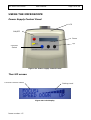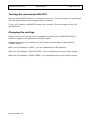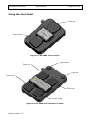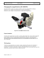
1
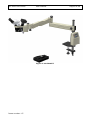
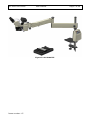
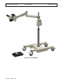
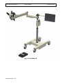
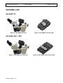
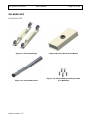
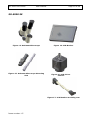
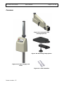
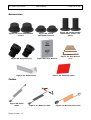
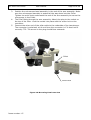
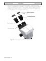
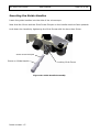
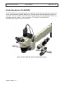
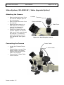
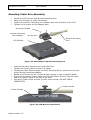
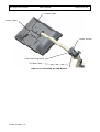
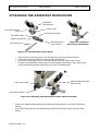
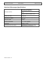
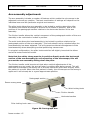
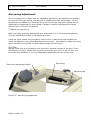
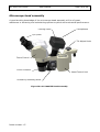
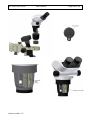
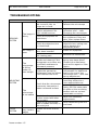
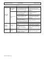
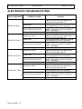
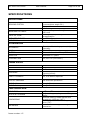
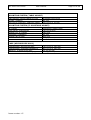
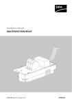
SOSO - 5000 SERIES
Oph
Ophthalmic Microscope
USER MANUAL
SCAN OPTICS
USER
MANUAL
SO-5000 TF
SO-5000 TFZ
SO-5000 SE
LED OPHTHALMIC
MICROSCOPE
SO-5000 LED Series
User Manual
Page 3 of 56
INDEX
INTRODUCTION ................................................................................................. 5
PACKING LIST ................................................................................................. 10
SO-5000 TF .................................................................................................. 10
SO-5000 TFZ / SFZ ....................................................................................... 10
SO-5000 SFZ ................................................................................................ 11
SO-5000 SE ................................................................................................. 12
Common ...................................................................................................... 13
Accessories .................................................................................................. 14
Cables ......................................................................................................... 14
ASSEMBLY INSTRUCTIONS ............................................................................... 15
Fixing the clamp ........................................................................................... 15
Table (TF / TFZ) ......................................................................................... 15
Floor Stand (SFZ / SE) ................................................................................... 16
Assembly of the Floor stand ......................................................................... 16
Assembling the Arm and Head ........................................................................ 18
Inserting the Guide Handles ........................................................................... 21
Guide Handle for SO-5000SE .......................................................................... 22
CONNECTING THE MICROSCOPE........................................................................ 23
Connecting to a power source ......................................................................... 24
Battery operation, maintenance and safety .................................................... 24
Connecting the Foot Pedal .............................................................................. 25
Connecting the Microscope Cables ................................................................... 26
Video System (SO-5000 SE / Video Upgrade Option) ......................................... 27
Attaching the Camera ................................................................................. 27
Connecting the Camera ............................................................................... 27
Mounting Video Arm Assembly ........................................................................ 28
ATTACHING THE ASSISTANT MICROSCOPE ......................................................... 30
Swapping from R/H to L/H configuration .......................................................... 31
Using The Assistant Microscope ....................................................................... 32
Focussing The Microscope............................................................................ 32
Fitting Sterilisable Covers ............................................................................... 33
Maintaining the Assistant Microscope ............................................................... 33
Cleaning .................................................................................................... 33
Storage ..................................................................................................... 33
Mould Protection ........................................................................................ 34
Assistant Microscope Specifications ................................................................. 35
Arm assembly adjustments ............................................................................ 36
Gas spring adjustment ................................................................................... 37
Microscope head assembly ............................................................................. 38
USING THE MICROSCOPE ................................................................................. 39
Power Supply Control Panel ............................................................................ 39
The LCD screen............................................................................................. 39
Turning the microscope ON/OFF ...................................................................... 40
Changing the settings .................................................................................... 40
Using the Foot Pedal ...................................................................................... 41
Changing the magnification (SO-5000TF) ......................................................... 42
Focus function............................................................................................ 42
Tilt function ............................................................................................... 42
STERILISATION ............................................................................................... 43
Issue number 1.5
SO-5000 LED Series
User Manual
Page 4 of 56
Moving the head into position ......................................................................... 43
Focusing the microscope ................................................................................ 44
ROUTINE CARE AND MAINTENANCE ................................................................... 45
Optical Head ................................................................................................. 45
Cleaning the optical components .................................................................. 45
Cleaning the plastic parts and paintwork ....................................................... 45
Protection against mould ............................................................................. 46
LIGHTING SYSTEM ........................................................................................... 46
Lamp life ...................................................................................................... 46
ADVANCED INSTRUCTIONS ............................................................................... 47
Replacing mould protection ............................................................................ 47
TROUBLESHOOTING ......................................................................................... 49
ELECTRONICS TROUBLESHOTTING .................................................................... 51
DISPLAY MESSAGE ............................................................................................ 51
POSSIBLE CAUSE .............................................................................................. 51
ACTION ........................................................................................................... 51
SPECIFICATIONS ............................................................................................. 52
Issue number 1.5
SO-5000 LED Series
User Manual
Page 5 of 56
INTRODUCTION
Please read the following information carefully before installing and using the Scan
Optics ophthalmic microscope. Scan Optics is responsible for the safety, reliability and
performance of the equipment only if it is used in accordance with these instructions.
This microscope is designed for use by a certified practitioner, for magnified
observation of patients, and for use in an operating theatre as an observation aid
during surgery. Environmental storage and packing conditions of 60-95% relative
humidity and 10-40 °C, are recommended for this product.
No parts or accessories supplied with this microscope are supplied in a sterile
condition.
Apart from those identified in the instructions within this manual, there are no userserviceable parts in this microscope. Scan Optics will retain the discretion to advise
whether any repairs may be taken out by external qualified technical personnel, or
whether part(s) of the microscope must be returned to the manufacturer’s premises
for service or repairs to be carried out under warranty or otherwise. Where
appropriately qualified technical personnel are identified by a user, and ratified by
Scan Optics, then Scan Optics will make available on request any information which
may assist in maintaining or repairing this equipment.
Scan Optics Pty Ltd
32 Stirling Street
Thebarton
SA 5031
AUSTRALIA
www.scanoptics.com.au
[email protected]
Issue number 1.5
SO-5000 LED Series
User Manual
Figure 1: SO-5000TF
Issue number 1.5
Page 6 of 56
SO-5000 LED Series
User Manual
Figure 2: SO-5000 TFZ
Issue number 1.5
Page 7 of 56
SO-5000 LED Series
User Manual
Figure 3: SO-5000 SFZ
Issue number 1.5
Page 8 of 56
SO-5000 LED Series
User Manual
Figure 4: SO-5000 SE
Issue number 1.5
Page 9 of 56
SO-5000 LED Series
User Manual
Page 10 of 56
PACKING LIST
SO-5000 TF
Figure 5: SO-5000 TF Head
Figure 6: SO-5000 TF Foot Pedal
SO-5000 TFZ / SFZ
Figure 7: SO-5000 T/S FZ Head
Issue number 1.5
Figure 8: SO-5000 T/S FZ Foot pedal
SO-5000 LED Series
User Manual
Page 11 of 56
SO-5000 SFZ
As SO-5000 TFZ
Figure 9: Floorstand legs
Figure 10: Floorstand Cross Beam
Figure 11: Floorstand Post
Figure 12: Floorstand mounting screws
(5 x M10x30)
Issue number 1.5
SO-5000 LED Series
User Manual
Page 12 of 56
SO-5000 SE
Figure 13: Assistant Microscope
Figure 15: Assistant Microscope Mounting
Arm
Figure 14: LCD Monitor
Figure 16: CCD Colour
Camera
Figure 17: LCD Monitor mounting arm
Issue number 1.5
SO-5000 LED Series
User Manual
Page 13 of 56
Common
Figure 19: Horizontal and
Pantograph Arm
Figure 20: Mounting clamp plates
Figure 18: Power Supply and
Pillar
Figure 21: Guide Handles
Issue number 1.5
SO-5000 LED Series
User Manual
Page 14 of 56
Accessories
Figure 22: Focus Sterilisable
Covers
Figure 25: Eyepiece (2x)
Figure 24: Guide Handle
Sterilisable Covers (2x
pairs)
Figure 23: Zoom
Sterilisable Covers
Figure 26: User Manual
Figure 28: Dust Covers
Figure 27: Hex Drivers
(7x)
Figure 29: Cleaning Cloth
Cables
Figure 30: Pillar
Cable
Issue number 1.5
Figure 31: Battery Cable
Figure 32: Mains Power Lead
SO-5000 LED Series
User Manual
Page 15 of 56
ASSEMBLY INSTRUCTIONS
Fixing the clamp
Table (TF / TFZ)
1.
2.
3.
4.
5.
6.
Insert the top plate clamp onto the bottom of the pillar.
Lock the clamp securely with screw and socket keys.
Insert the lower clamp plate onto the pillar.
Position the lower clamp to approximately the width of the surface being
clamped to.
Lock the lower clamp with the clamp locking lever.
Secure the clamp by rotating the clamp shaft knob clockwise.
Top Plate Clamp
Top Clamp locking
screw
Lower Plate Clamp
Lower Clamp
locking lever
Clamp shaft
Clamp shaft
locking knob
Figure 33: Clamp assembly
Issue number 1.5
SO-5000 LED Series
User Manual
Page 16 of 56
Floor Stand (SFZ / SE)
Assembly of the Floor stand
The Floor Stand will need to be assembled in two parts.
1.
2.
3.
Lay the Floor Stand legs upside down on a flat surface.
Place the Cross Beam face down into the cut-outs on the legs.
Use the provided M10 screws to lock the legs and Cross Beams together.
Legs
Screws
Cross Beam
Screws
Figure 34: Floor stand base assembly
4.
5.
Lean the assembled Floor Stand base on it’s side and insert the post.
Insert the post locking screw from the underside and lock the post securely.
Post
Screw
Figure 35: Floor Stand post assembly
Issue number 1.5
SO-5000 LED Series
6.
7.
8.
User Manual
Page 17 of 56
Right the Floor Stand up on it’s four wheels and lock the wheel using the
wheel lock.
Insert the Pillar and Power Supply assembly into the Floor Stand Post.
Secure the Pillar by tightening the Pillar locking screws.
Pillar Locking
Screws
Wheel lock
Figure 36: Floorstand and Pillar assembly
Issue number 1.5
SO-5000 LED Series
User Manual
Page 18 of 56
Assembling the Arm and Head
1.
2.
Locate the pillar safety clamp and place it on the pillar if it is not there
already. Tighten the pillar safety clamp at a point on the pillar.
Place the arm assembly on the pillar. Make sure that the arm assembly rests
against the pillar safety clamp. Loosen the elbow knob to allow the pantograph
arm to rotate about the elbow joint.
Elbow locking knob
Pantograph Arm
Pillar
Horizontal arm
locking knob
Safety clamp
Horizontal Arm
Figure 37: Arm Assembly
Issue number 1.5
SO-5000 LED Series
3.
4.
5.
User Manual
Page 19 of 56
Position the microscope head assembly in the end of the arm assembly. Make
sure the microscope assembly is seated all the way down into the Collet.
Tighten the wrist knob underneath the end of the arm assembly to secure the
microscope in the Collet.
The Pillar Cable through the arm assembly. Attach the plug to the socket on
the top of the Pillar. Lock the socket into place with the screw lock on the
connector.
Connect the other end of the pillar cable to the underside of the Lamphouse.
The connector is polarised, so do not force the connector in if it does not fit
correctly. TIP: The arrow on the plug should face outwards.
Collet
Wrist Lock
Figure 38: Mounting Head onto Arm
Issue number 1.5
SO-5000 LED Series
6.
User Manual
Page 20 of 56
Remove the eyepiece blanks and insert the eyepieces. Insert the focusing
eyepiece in the LHS eyepiece tube from the observer’s perspective and secure
in place so that the scale marker is easily visible. Place the fixed eyepiece in
the RHS eyepiece tube and secure using the screw. Retain the eyepiece caps
in a safe place for when storing the microscope.
Eyepiece blanks
Focusing Eyepiece
Fixed Eyepiece
Securing Screw
Figure 39: Inserting Eyepiece (SO-111TZ/SZ depicted)
Issue number 1.5
SO-5000 LED Series
User Manual
Page 21 of 56
Inserting the Guide Handles
Insert the guide handles into the side of the microscope.
Note that the Grove and the Grub Screw Dimple on the handle needs to face upwards.
Lock down the handle by tightening the Grub Screw with the 4mm Hex Driver.
Grub Screw Dimple
Grove on Guide Handle
Locking Grub Screw
Figure 40: Guide Handle Assembly
Issue number 1.5
SO-5000 LED Series
User Manual
Page 22 of 56
Guide Handle for SO-5000SE
The SO-5000SE comes supplied with an Assistant Microscope and hence the mounting
of the guide handle is slightly different on the side where the Assistant Microscope is
mounted. You will need to insert the longer guide handle into the Assistant Microscope
Mounting bracket instead. See the Section: ATTACHING THE ASSISTANT
MICROSCOPE, page 30, for more details
Figure 41: SO-5000 SE with Assistant Microscope
Issue number 1.5
SO-5000 LED Series
User Manual
Page 23 of 56
CONNECTING THE MICROSCOPE
Footpedal connection
Battery connection
3A Overload
Circuit Breaker
Mains cable
IEC connection
Figure 42: Power Supply Bottom Panel
Camera Power (SE
and camera option
models only)
Zoom socket
(TFZ and SE
models only)
Pillar cable input
connection
Figure 43: Head Control Unit Panel
Pillar Output Socket
LCD Power Socket
Figure 44: Pillar Panel
Issue number 1.5
SO-5000 LED Series
User Manual
Page 24 of 56
Connecting to a power source
The Scan Optics Ophthalmic Microscope may be connected to either an earthed mains
(100-240V) ac supply, or a 12V dc supply, or both.
•
•
•
•
Connect the Mains IEC orange cable to the IEC socket on the bottom of the
power supply.
Lock the IEC cable with the cable clip to ensure it is secure and can not be
pulled out.
Connect the Battery Cable to the battery socket connection on the bottom of
the Power Supply. Tighten the locking screws to ensure that it does not come
off.
See Figure 42: Power Supply Bottom Panel
Battery operation, maintenance and safety
Scan Optics recommend the use of gel cell or sealed rechargeable lead-acid 12V
batteries. These batteries are maintenance-free and can be operated, charged or
stored in any position without leakage.
•
•
•
•
•
•
If the power supply is to be connected to a 12-volt dc supply, connect the
Battery Cable to the connector on the bottom panel on the Power Supply.
Connect the Red Battery Clip to the positive battery terminal, and the black clip
to the negative battery terminal. The power supply will not operate if the
terminals are reversed.
The 12 volt supply must be direct current. The power supply will not operate
with 12 volts alternating current.
Ensure batteries have adequate airflow around them before charging.
Avoid short-circuiting batteries.
Old lead-acid batteries of any type must be disposed of correctly. It is
recommended that they are recycled by an appropriate establishment who
recycle car batteries. Lead acid batteries should not be disposed of with
ordinary waste, as lead poisoning or acid trauma may result.
Where battery backup is used, Scan Optics recommends a periodical check of the
battery to ensure it is charged and functional.
Connecting the battery whilst the microscope is running on mains will not charge the
battery.
Depending on the state of the battery charge levels, the microscope will attempt to
automatically switch to battery mode when there is a failure with mains power.
However, when battery level is low, the automatic change over will not occur and a
manual power-up will be required to restart the microscope. If you require a
continuous power source, it’s recommended that you use an Uninterruptible Power
Supply (UPS) to back up your mains supply.
Issue number 1.5
SO-5000 LED Series
User Manual
Page 25 of 56
Connecting the Foot Pedal
The Footpedal will allow the surgeon the convenience of hands free control of the
zoom, focus and light settings (depending on your model) and still stay sterile.
To connect the Footpedal, connect the socket to the bottom of the Power Supply.
See Figure 42: Power Supply Bottom Panel
Tighten the screws lock to ensure that the plug does not fall out during use.
Foot pedal
Battery
IEC Mains Cable
Figure 45: Power Supply Connections
Issue number 1.5
SO-5000 LED Series
User Manual
Page 26 of 56
Connecting the Microscope Cables
•
•
•
•
Plug the DB9 Way Plug to the top of pillar and tighten the screws locks to
ensure it does not pull out.
Plug the Mini DIN Plug end to the Head Control Unit Pillar Input Socket. The
Socket has orientation keying so it’s important that you DO NOT FORCE THE
CONNNECTOR in.
Plug the Zoom Cable firmly into the Head Control Unit (for SFZ, TFZ and SE
models only)
Plug the Lamphouse cable into the Lamphouse. Ensure orientation is correct.
DO NOT FORCE CONNECTOR.
Lamphouse cable
Zoom cable
(SFZ, TFZ and
SE models only)
Pillar cable
Figure 46: Head Control Unit Connections
Lamphouse cable
Figure 47: Lamphouse Connection
Issue number 1.5
SO-5000 LED Series
User Manual
Page 27 of 56
Video System (SO-5000 SE / Video Upgrade Option)
Attaching the Camera
•
•
•
•
Remove the dust cover from
the camera adapter part on
the microscope.
Remove the dust cover from
the camera.
Keep the dust covers in a
safe place if you need to
remove the camera for
storage in the future.
Screw the camera into the
camera adapter. Be careful
that you do not cross thread
the camera. The camera
should be square once it’s
fully tightened. See figure
below
Connecting the Camera
•
•
•
Locate the Camera Power
Cable.
Connect the one end of the
power cable to the Head
Control Unit and the other
end to the Camera.
Connect the S-Video Cable
to the Camera
Issue number 1.5
Camera
Camera Adapter
Dust Cover
Figure 48: Attaching the camera
Power Cable
S-Video Cable
SO-5000 LED Series
User Manual
Page 28 of 56
Mounting Video Arm Assembly
•
•
•
•
Locate the LCD Monitor and Monitor Mounting Arm.
Place the LCD down a clean flat surface.
Position the Monitor Mounting Arm Adapter part onto the back of the LCD
Tighten the 4 screws on the Adapter part.
Mounting Screws
Monitor Mounting
Arm Adapter
Monitor Mounting
Arm
LCD Monitor
Figure 49: Attaching the Monitor Mounting Arm
•
•
•
•
•
•
Lower the Monitor Mounting Arm onto the Pillar.
Tighten the Locking Knob so that it is stable.
Thread the video cable through the Pillar Mounting Block, up the arm and exit
at the Monitor Mounting Adapter.
Rotate the LCD Monitor so it is flat for easy access to the connection panel.
Plug the LCD Monitor Power Cable into the LCD Power Socket. Plug the other
end of the power cable to the top of the Pillar.
Plug the S-Video Cable into the S-Video Input socket. DO NOT FORCE
CONNECTOR.
S-Video Socket
Power Socket
Figure 50: LCD Monitor Input Panel
Issue number 1.5
SO-5000 LED Series
User Manual
Page 29 of 56
S-Video Cable
Power Cable
Power socket
Pillar Mounting Block
S-Video Cable
Figure 51: Connecting the LCD Monitor
Issue number 1.5
SO-5000 LED Series
User Manual
Page 30 of 56
ATTACHING THE ASSISTANT MICROSCOPE
Assistant
Microscope
Focus Knob
Microscope Lock
Knob
Threaded Hole
Microscope Mount
Angle Lock Knob
Mounting Arm
Mounting Arm
Lock Screw
Figure 53: Assistant
Microscope Assembled
Figure 52: Assistant Microscope Parts
•
•
•
•
Remove the Mounting Arm Lock Screw from the Microscope Mount.
Slide the Microscope Mount onto the Mounting Arm.
Lock the Mounting Arm Lock Screw tightly with the 5mm Hex Driver.
Position the Assistant Microscope to the Microscope Mount, then secure by
locking the Microscope Lock Knob into the Threaded Hole.
M8 Grub Screw
Assembled Assistant
Microscope
Accessory Mount
Figure 54: Attaching Assistant Microscope to Main Assembly
•
•
Insert the Assembled Assistant Microscope Mounting Arm into the Accessory
Mount.
Lock the Mounting Arm by tightening the M8 Grub Screw using the 4m Hex
Driver.
Issue number 1.5
SO-5000 LED Series
User Manual
Page 31 of 56
Swapping from R/H to L/H configuration
The previous procedure shows the assistant microscope being attached to the R/H
side of the main microscope. However the assistant microscope can also be configured
so it can be attached to the L/H side if required.
•
•
•
•
•
•
Remove the Assistant Microscope Assembly from the Accessory Mount, by
loosening the M8 Grubscrew
Remove the Assistant Microscope from the Microscope Mount, by undoing the
Microscope Lock Knob.
Insert the arm into the Accessory Mount on the L/H side.
The mount has to be rotated 180, simply undo the Angle Lock Knob about 5mm
(this will disengage the limit travel pins) rotate the mount and re tighten the
Angle Lock Knob.
Re-attach the Assistant Microscope to the mount and adjust the angle for
optimum position.
Re-attach the short guide handle to the R/H Accessory Mount Block.
Issue number 1.5
SO-5000 LED Series
User Manual
Page 32 of 56
Using The Assistant Microscope
Focussing The Microscope
To focus the Binocular Assistant Microscope, first focus the main microscope according
to the instructions in its manual. It may be helpful to focus on a target such as the
one printed on this page.
Figure 55: Assistant Microscope Setup Target
•
•
•
•
Hold the Assistant Microscope head assembly with one hand and loosen the
Angle Lock Knob slightly. Look through the eyepieces of the Binocular Assistant
Microscope and manoeuvre the microscope until the target is centred in the
vertical plane.
Tighten the Angle Lock Knob and focus the assistant microscope using its own
focus knob(s) while looking through the RHS eyepiece only with the right eye.
Re-check the vertical alignment and adjust the position of the Assistant
Microscope head if necessary after loosening the angle lock knob. Re-tighten
the Angle Lock Knob when vertical alignment is achieved.
Look through the LHS (adjustable) eyepiece with the left eye and rotate the
collar until the left eye is in focus. Housings are not geared together and need
to be adjusted to a symmetrical position manually.
Issue number 1.5
SO-5000 LED Series
User Manual
Page 33 of 56
When this procedure is complete the microscope should be centred on the vertical
plane of the target and focussed on the centre of the target, although there may be
some left-right displacement.
To correct for left-right displacement, loosen the microscope lock knob and swivel the
microscope head assembly left or right slightly until the centre of the target is in the
centre of the view. Tighten the microscope lock knob to secure the assembly.
The assistant microscope should stay focussed so long as the image through the main
microscope is focussed.
Adjust the pupillary distance (PD) of the assistant microscope to a comfortable setting
by rotating the prism housings apart or together as required.
Fitting Sterilisable Covers
Sterilisable covers can be fitted to the manual focus knobs of the assistant microscope
and will also fit on the angle lock knob and microscope lock knob if required.
Additional sterilisable covers may be purchased from Scan Optics in the event of loss
or damage.
The covers may be sterilised by:
•
•
•
•
boiling
autoclaving
chemical sterilisation
gas sterilisation.
Note that national authorities may require the use of specific sterilisation or
disinfection methods.
Maintaining the Assistant Microscope
Cleaning
Regular inspection and cleaning of the microscope will ensure reliable operation. In
particular, check the objective lens and eyepieces for cleanliness each time the
instrument is used. Surface dust should be removed with a clean, soft brush.
Fingerprints, irrigation solution residue and grease may be removed by lightly wiping
with a cotton cloth or lens tissue moistened with a mixture of 70% ether and 30%
absolute alcohol (either ethanol or methanol). If this mixture is unavailable, pure
alcohol can be substituted. Do not use acetone as it may damage the surface
coatings of the lenses.
Storage
While not in use, the SO-1440 binocular assistant microscope should be stored
carefully, with the eyepiece caps in place to prevent accidental damage. If the
microscope is to be stored or transported, it is recommended that the original
Issue number 1.5
SO-5000 LED Series
User Manual
Page 34 of 56
packaging be re-used for this purpose. If possible, re-pack each assembly in its
original plastic bag. The best storage location is a low humidity, dust-free
environment, such as an air-conditioned room.
Mould Protection
The SO-1440 binocular assistant microscope is fitted with anti-mould protection which
is effective for approximately three years. However, the effective life of this
protection will depend on environmental factors such as the temperature and humidity
of the place where the microscope is stored. Regular inspection of the microscope will
help early identification of mould and alert the user of the need to replace the antimould protection.
To replace the anti-mould protection
pellet:
• Slightly loosen the grubscrew at
the top of the objective
assembly.
• Remove the four M3x20 socket
head cap screws from the
objective assembly.
• Remove the existing anti-mould
pellet.
• Remove the adhesive backing
from the new pellet and secure
it in place. Note that where the
pellets are supplied in pairs,
scissors can be used to separate
the pair and trim the corners of
the single pellet.
• Replace the objective assembly
by securing the M3x 20 socket
head cap screws again.
Issue number 1.5
SO-5000 LED Series
User Manual
Page 35 of 56
Assistant Microscope Specifications
VIEWING SYSTEM
Binocular, stereoscopic
(convergence angle 10o)
Orientation 90o to main microscope
view
Eyepiece tube inclination 20-25o
MAGNIFICATION
Fixed, 8x
WORKING DISTANCE
Auxiliary objective to object distance
270 mm
FIELD OF VIEW
30mm
REFRACTIVE ERROR
+/- 5D left eyepiece
FOCUSING
Range ± 20mm
INTERPUPILLARY DISTANCE
Adjustable for Distance PD range
approximately 56 to 80mm
Issue number 1.5
SO-5000 LED Series
User Manual
Page 36 of 56
Arm assembly adjustments
The arm assembly includes a number of features which enable the microscope to be
adjusted in almost any position. The best combination of settings will depend on the
individual user and the particular surgical environment.
The pillar knob allows the arm assembly to be locked in position about the pillar.
The elbow knob allows the shape of the arm to be locked in position; that is the
position of the pantograph section relative to the horizontal section of the arm
assembly.
The friction handle allows the vertical movement of the pantograph section of the arm
assembly to be restricted or locked in position.
The wrist knob allows the head assembly to be locked in position relative to the
pantograph section of the arm assembly. This knob should not be unlocked after the
head assembly has been adjusted. This will prevent accidental dislodgement of the
head assembly when attempting vertical positioning manoeuvres.
In a typical configuration; the pillar knob would be left slightly loose but the elbow
and wrist knobs would be locked.
Note that the safety clamp must be in position directly under the horizontal
section of the arm assembly for safe operation of the microscope; this will
prevent the arm assembly sliding down the pillar.
The friction handle could be set such that when vertical adjustments of the
pantograph arm are made, the arm will stay in position after being moved. This will
allow the microscope to be swung out of the way about the pillar after surgery while
the patient is moved. When the next patient is ready, the microscope can be swung in
again and it will already be in a good approximate position.
Pantograph section
Elbow locking knob
Wrist locking knob
Friction Handle
Horizontal section
Pillar locking knob
Figure 56: Pantograph Arm
Issue number 1.5
SO-5000 LED Series
User Manual
Page 37 of 56
Gas spring adjustment
The microscope arm is fitted with an adjustable gas spring. By adjusting the position
of one end of the gas spring, the amount of upward force can be changed. Thus if
accessories are added to or removed from the microscope, the force setting can be
adjusted to compensate for the change in weight, thereby maintaining the same
desired ‘feel’ of the arm movement.
To adjust the gas spring:
With one hand, push the pantograph arm down until it is in the horizontal position.
This will expose the socket in the adjusting screw.
Using the 5mm socket key provided in the tool box, rotate the screw clockwise to
move the adjusting nut up and decrease the arm force. Alternatively rotate the screw
anti-clockwise to move the nut down and increase the arm force.
CAUTION:
Always check the arm movement over the entire up/down stroke of the arm. If the
microscope is heavily loaded with accessories and the arm force is set too low, the
arm may drop suddenly if it is not adequately restrained with the friction lock.
Gas spring adjustment shaft
Gas spring
Adjusting Nut
Figure 57: Gas Spring Adjustment
Issue number 1.5
SO-5000 LED Series
User Manual
Page 38 of 56
Microscope head assembly
A good working knowledge of the microscope head assembly will be of great
assistance in achieving and maintaining optimum optical and mechanical performance.
Cooling Vents
Lamphouse
Eye piece
Tilt Adjust Knob
Focus Control
Prism Protector
Head Control Unit
Accessory Mounting Block
Figure 58: SO-5000TFZ Head Assembly
Issue number 1.5
SO-5000 LED Series
User Manual
Page 39 of 56
USING THE MICROSCOPE
Power Supply Control Panel
LCD
ON/OFF
Down
Up
Function
Select
Figure 59: Power Supply Control Panel
The LCD screen
Current Function Mode
Setting Level
Figure 60: LCD Display
Issue number 1.5
SO-5000 LED Series
User Manual
Page 40 of 56
Turning the microscope ON/OFF
Hold the red ON/OFF button for 1 second to turn it on. The microscope will go through
it’s start up and power up normally within 2 seconds.
To turn off, hold the red ON/OFF button for 1 second. The microscope will turn off
automatically.
Changing the settings
Settings on the microscope can be changed by pressing the “FUNCTION SELECT”
button to toggle to the settings you want to adjust.
Increase the setting by pressing the “UP” button and decrease by pressing the
“DOWN” button.
When the LCD displays “LIGHT”, you are adjusting the LED intensity.
When the LCD displays “FOCUS SPEED”, you are adjusting the focus motor speed.
When the LCD displays “ZOOM SPEED”, you are adjusting the zoom motor speed.
Issue number 1.5
SO-5000 LED Series
User Manual
Page 41 of 56
Using the Foot Pedal
Focus Up
Focus Down
Figure 61: SO-5000 TF Foot Pedal
Zoom In
Light Down
Light Up
Zoom Out
Focus Up
Focus Down
Figure 62: SO-5000 TFZ/SFZ/SE Foot Pedal
Issue number 1.5
SO-5000 LED Series
User Manual
Page 42 of 56
Changing the magnification (SO-5000TF)
The SO-5000TF model has manual variable continuous magnification settings.
Rotate the zoom adjust knob forward to increase magnification.
Rotate the zoom adjust knob backwards to decrease magnification.
Figure 63: SO-5000TF Manual Zoom
Focus function
To focus the microscope up or down, use the appropriate foot control pedal. The total
focus range is 50mm. For optimum microscope use, leave the microscope head in
such a position to allow approximately 25mm of focus range in each direction.
Sterilisable covers are provided for fitting over the manual focus knob when sterile
use is required.
Tilt function
To tilt the head assembly up or down, simply rotate the tilt knob anti-clockwise or
clockwise accordingly. Note that the entire head assembly will tilt, not just the
eyepieces. To ease this operation, support the weight of the microscope head with one
hand while using the other hand to rotate the knob.
Issue number 1.5
SO-5000 LED Series
User Manual
Page 43 of 56
STERILISATION
Scan Optics microscopes are supplied with two sets of sterilisable covers – one set
may be used while the other set is undergoing sterilisation. Additional sterilisable
covers may be purchased from Scan Optics in the event of loss or damage. Simply slip
the covers on to the zoom or focus knobs when required.
The covers may be sterilised by:
• boiling
• autoclaving
• chemical sterilisation
• gas sterilisation
Note that national authorities may require the use of specific sterilisation or
disinfection methods.
Moving the head into position
Note that sterilised covers should be applied to the manual focus and zoom knobs and
the guide handle (if used) before these parts of the microscope are touched by a
sterile operator.
Move the head into approximate position using the arm assembly articulations.
Move the microscope focus up to the half-way position. This should leave
approximately 25mm of movement up or down from the central position.
Use the pantograph arm articulation to move the head up or down while looking
through the eyepieces to roughly focus the microscope.
If the microscope eyepieces are higher than the most comfortable position for the
operator and it is not possible or practical to adjust the operator’s seat, rotate the tilt
knob clockwise to tilt the head of the microscope down. The range of tilt adjustment
is from 45° downward to 5° above the horizontal.
Issue number 1.5
SO-5000 LED Series
User Manual
Page 44 of 56
Focusing the microscope
Focussing the microscope in the correct sequence is an important step in setting up
for use.
• Set the refractive error scale to zero on the LHS eyepiece.
• Choose a high magnification zoom setting or one which is typically used in
surgery.
• Close the left eye and look through the right eyepiece of the microscope with
the right eye only.
• Focus the microscope slowly until the image is sharply in focus.
• Close the right eye and look through the left eyepiece of the microscope with
the left eye only.
• Rotate the refractive error adjustment ring on the left eyepiece until the left eye
is in focus. The reading on the ring will give an approximate measure of the
relative refractive error between the left and right eyes.
• Look through both eyepieces normally and check that the image is focussed and
that stereopsis is achieved.
Issue number 1.5
SO-5000 LED Series
User Manual
Page 45 of 56
ROUTINE CARE AND MAINTENANCE
Optical Head
Cleaning the optical components
Prism
The eyepieces, objective lens and
lamphouse prism should be checked for
cleanliness each time the instrument is
used. Surface dust should be removed
with a clean, soft brush. Fingerprints,
irrigation solution residue and grease
may be removed by lightly wiping with
a cotton cloth or lens tissue moistened
with a mixture of 70% ether and 30%
absolute alcohol (either ethanol or
methanol). Use pure alcohol if no ether
is available.
Objective lens
Do not use acetone as it may damage
the surface coatings of the lenses.
Figure 64: Underside view
Cleaning the plastic parts and paintwork
Use water based cleaners only.
Do not use any organic solvent such as alcohol, ether or xylene.
Do not dismantle.
Apart from instructions specifically mentioned within this manual, no parts inside the
optical head of the instrument can be serviced by the user. Attempts to dismantle the
optical head or prism cover will make any warranty void.
Issue number 1.5
SO-5000 LED Series
User Manual
Page 46 of 56
Protection against mould
In hot and humid climates it is common for mould to grow on optical surfaces.
Cleaning and repairing the damage can be expensive and inconvenient. To minimise
the risk of mould forming, do not leave the instrument without either eyepieces or
eyepiece blanks inserted and always store the optical head in a sealed bag containing
silica gel desiccant. Scan Optics SO-111W microscopes are fitted with anti-mould
protection. In tropical climates, routine checking for the presence of mould is
recommended.
LIGHTING SYSTEM
Lamp life
The LED is rated for an operational life of about 10 years of normal use. No servicing
is required but users should be aware that small degradation of light intensity will be
noticeable over the life of the LED.
Issue number 1.5
SO-5000 LED Series
User Manual
Page 47 of 56
ADVANCED INSTRUCTIONS
Replacing mould protection
The microscope is fitted with anti-mould protection which is effective for
approximately three years. However, the effective life of this protection will depend on
environmental factors such as the temperature and humidity of the place where the
microscope is stored. Regular inspection of the microscope will help early identification
of mould and alert the user of the need to replace the anti-mould protection.
To replace the anti-mould pellet:
1.
2.
3.
4.
5.
6.
7.
8.
9.
10.
11.
12.
Zoom the microscope to the lowest magnification setting
Loosen the retaining screw on the front of the microscope head.
Lift the microscope out of the mounting ring
Remove the prism protector from the auxiliary objective assembly by
prying it apart
Unscrew the cover from the bottom of the microscope head. The location of
the existing anti-mould pellet will be revealed from the front of the
microscope head.
Remove the old anti-mould pellet.
Peel the adhesive backing from the new anti-mould pellet and place it in
the same location.
Zoom the microscope in and out all the way to make sure the zoom optics
do not dislodge the pellet.
Screw the cover back on.
Replace the prism protector on the auxiliary objective assembly, making
sure that the slot lines up with the location of the lamphouse prism.
Replace the microscope head back in the mounting ring and re-tighten the
retaining screw.
Update the anti-mould label on the microscope head, or replace it with a
new label.
Issue number 1.5
SO-5000 LED Series
Issue number 1.5
User Manual
Page 48 of 56
SO-5000 LED Series
User Manual
Page 49 of 56
TROUBLESHOOTING
SYMPTOM
The image is
blurry
VIEWING
SYSTEM
FIRST STEP
If the microscope or object
has moved it may no
longer be in focus.
A different user may
require adjustment for
their refractive error.
Check the eyepieces for
cleanliness.
Check the objective lens
for cleanliness.
No image is
seen
The
microscope
is falling
under its
own weight
MOUNTING
SYSTEM
Locate the gas spring
adjustment near the elbow
joint between the arms.
Check that the microscope
is securely clamped to a
stable horizontal surface
The
microscope
is not stable
FOCUS
SYSTEM
Check that the eyepieces
have been inserted.
Check for obstructions in
the viewing path
Loosen the arm friction
handle and observe if the
pantograph arm offers any
significant resistance to
downward pressure
The Focus is
very hard to
adjust
Issue number 1.5
Check that the appropriate
friction knobs have been
set correctly
Check if the microscope
head is seated correctly in
the wrist joint
Loosen the focus friction
lock.
REMEDY
Refocus the microscope
Adjust the eyepieces for
refractive error – refer
Focussing the microscope.
Carefully remove and clean
the eyepieces if they are
dirty, then replace them.
Carefully clean the
objective lens, taking care
not to damage the
lamphouse prism.
Insert the eyepieces.
Remove the obstruction.
If it does not then the gas
spring may have failed.
Contact your distributor,
local service agent or Scan
Optics.
Adjust the gas spring to
compensate for additional
load on the end of the
microscope arm - refer Gas
spring adjustment
If not, change the
mounting surface to a
more appropriate one.
Use the optional Scan
Optics SO-291 table plate
to stiffen a thin mounting
surface such as a sheetmetal table or trolley.
Refer Arm assembly
adjustments
Refer Assembling the arm
and head
SO-5000 LED Series
SYMPTOM
User Manual
FIRST STEP
The light is
too dim
Check the intensity setting
on the front panel. The
intensity may be set low.
Check if there is mains
power available (green LED
on the front panel)
LIGHTING
SYSTEM
There is no
light
POWER
SUPPLY
FOCUS
MOTOR
There is no
power
There is no
power to
motor
Issue number 1.5
Page 50 of 56
REMEDY
Increase the lamp intensity
by switching the Light
Mode and increase the light
intensity.
Switch to battery power if
no mains power is
available.
Check the intensity setting
on the front panel. The
intensity may be set to
zero.
Increase the lamp intensity
by switching the Light
Mode and increase the light
intensity.
Check if the cable is
connected to the socket on
the top panel of the Pillar
If not, connect it.
Check the power supply
Check the mains power
supply
Turn the mains power off
and check the circuit
breaker on the bottom
panel
Screw in grubscrews on
side of focus box, remove
focus box, check wires for
damage or kinking
See below
Use battery power if no
mains power is available.
Push the circuit breaker
back in after waiting a few
minutes.
Straighten wires and
ensure wires are pushed
firmly on to connector
SO-5000 LED Series
User Manual
Page 51 of 56
ELECTRONICS TROUBLESHOTTING
DISPLAY MESSAGE
ZOOM IN FAULT
POSSIBLE CAUSE
Electronics frozen.
Pedal stuck.
Micro switch not activating.
Micro switch faulty.
Electronics frozen.
ZOOM OUT FAULT
Pedal stuck.
Micro switch not activating.
Micro switch faulty.
Electronics frozen.
FOCUS IN FAULT
Pedal stuck.
Micro switch not activating.
Micro switch faulty.
Electronics frozen.
FOCUS OUT FAULT
Pedal stuck.
Micro switch not activating.
Micro switch faulty.
Issue number 1.5
ACTION
Reset the Unit by switching off and on
again or remove the mains power then
reconnect and switch back on.
Check under pedal and remove anything
that might prevent normal movement.
Listen for a click when depressing the
pedal. Contact Scan Optics for advice If
click is not audible.
Contact Scan Optics for advice.
SO-5000 LED Series
User Manual
Page 52 of 56
SPECIFICATIONS
OPTICAL HEAD
VIEWING SYSTEM
MAGNIFICATION
WORKING DISTANCE
FIELD OF VIEW
REFRACTIVE ERROR
FOCUSING
Binocular, stereoscopic
(convergence angle 10o)
Eyepiece tube inclination 45o
Zoom magnification, range 4.2 x - 25x
Auxiliary objective to object distance
160 mm
15 - 65mm, depending on
magnification
+/- 5D left eyepiece
Range ± 25mm
ILLUMINATION
LAMP
FILTERS
Coaxial with viewing system, high
intensity
20W LED
Internal ultraviolet filter, 435nm.
LAMP LIFE
Minimum 10 years
ILLUMINATION
50,000 Lux (minimum)
ALIGNMENT
POWER SUPPLY
MAINS POWER
OUTPUT
INTENSITY CONTROL
EARTHING
110-240V
Regulated output
9 Levels
Via earth lead of mains power cable
(green/yellow)
DIRECT CURRENT
15 V dc source optional
CIRCUIT BREAKER
3A Overload protection
CABLE: Mains
CABLE: Battery
Length 5 metres
Length 3 metres
PANTOGRAPH ARM
HEAD TILT
VERTICAL TENSION
DIMENSIONS
MATERIALS
Issue number 1.5
+5o to -45o
Adjustable gas spring to set lifting
force
Vertical pillar to head optical axis
maximum 1025mm (40")
Pantograph arm vertical range 360
mm (14")
No ferrous metals, preventing
corrosion.
SO-5000 LED Series
User Manual
Page 53 of 56
MOUNTING SYSTEM (TABLE MOUNT)
TWO HEIGHT ADJUSTABLE PLATES
CLAMP (THROAT)
TOP PLATE CONTACT SURFACE AREA
Anodised Aluminium
80 mm
150 x 160 x 20 mm
MOUNTING SYSTEM (FLOORSTAND MOUNT)
‘H’ FRAME
FOOTPRINT DIMENSION
HEIGHT OF ‘H’ FRAME
GROUND CLEARANCE
HEIGHT WITH POST
WEIGHT
WHEEL DIAMETER
Powdered Coated Steel
790 x 520 mm
185 mm
60 mm
804 mm
36Kg (79 lbs)
100 mm
CASE (MICROSCOPE ONLY)
DIMENSIONS: Aluminium case
DIMENSIONS: Standard packaging
WEIGHT: In aluminium case
WEIGHT: In standard packaging
Issue number 1.5
790 x
810 x
30 kg
22 kg
560 x 340 mm
520 x 290 mm
(66 lbs)
(49 lbs)
SO-5000 LED Series
User Manual
Page 54 of 56
Scan Optics is a Quality Endorsed Company, certified to the International Organisation
for Standardisation (ISO) standard ISO 9001, Quality Systems - Model for quality
assurance in design, development, production, installation and servicing. This
certification recognises the importance placed by Scan Optics on providing the highest
levels of quality in all aspects of business.
The rules for accreditation of a Quality Endorsed Company are laid down in the
international standards ISO/IEC Guide 48 and EN 45012. They require a complete
auditing of all company systems and procedures by an independent accredited
certification body every three years. The QAS (Australia) accreditation is recognised
by most of the world’s major quality certification bodies including BSI(UK), UL(USA),
QMI(Canada), and JQA(Japan). In addition, EQNet Quality Certification which is
recognised by some twenty countries, and specific registration with any one of more
than sixty national certification bodies, can be provided if required.
To achieve ISO 9001 accreditation requires quality in product design, in manufacture,
in customer service and in all internal company systems.
SO-5000 LED Series
User Manual
Page 55 of 56
All Scan Optics equipment has been designed and manufactured to provide reliable service and is
warranted to be free from defects of material and construction at the time of purchase.
Should the instrument require repair or service due to faulty parts or labour this repair will be carried out by
Scan Optics or its agents free of charge during the warranty period of:
One year – on all electronics
Two years – on all mechanical parts
Terms and Conditions
This warranty will not apply if a defect is caused:
•
•
•
•
•
•
during shipping or transit
by humidity or dampness
by operation on a supply voltage other than as specified in the instructions
by incorrect connection to a power supply
by alteration or repair by anyone other than a person authorised by Scan Optics, or
by any other misuse, accident or neglect.
Service and Repair
In the case of a warranty claim Scan Optics should be immediately contacted, either directly or through the
agent, distributor, donor or supplier of the equipment. You will need to provide copies of the purchase or
delivery documents.
Scan Optics will then send instructions regarding the repair, replacement or return of the equipment.
When freight is arranged by Scan Optics or its agent, the cost of the freight will be accepted by Scan Optics;
all other freight costs are the responsibility of the purchaser.
SO-5000 LED Series
User Manual
OUR COMMITMENT TO YOU
We at Scan Optics are committed to the highest
quality in our products and in the services we
provide.
Page 56 of 56
WE WELCOME YOUR FEEDBACK
If you would like to comment on any matter
relating to a Scan Optics product or service,
you can contact us in the following ways:
Our goal is for you to be a satisfied customer of
Scan Optics.
•
by mail, using the attached
pre-addressed card if you wish
We undertake:
•
by telephone, on
61 (8) 8234 9120
•
by facsimile, on
61 (8) 8234 9417
•
by e-mail, at
[email protected]
•
to listen carefully to what you tell us
•
to be accurate and honest
in telling you about our
products and services
•
•
to communicate with you
professionally and in clear
language
to deal promptly with any
complaints or concerns
you may have with us.
At Scan Optics we have a system
of continuous product improvement. We
welcome suggestions at any time for
modifications and improvements.
If you wish to discuss a particular
item of equipment, please tell us the model
and serial number.
We also welcome customers and users of Scan
Optics equipment to visit us. If you are able
to do so, please contact us so we can make
arrangements.
MICROSCOPE DETAILS
Customer
Shipping Date
Model #
Power Supply #
Microscope Head #
SO-5000 LED Series
User Manual
Page 57 of 56