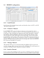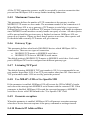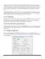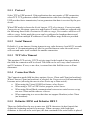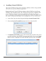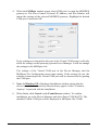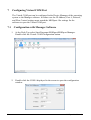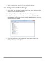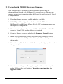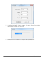
1
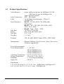
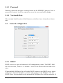
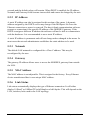
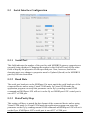
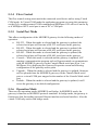
MODBUS TCP to RTU/ASCII Gateway Users Manual Model MODport-101, MODport-102, MODport-104 July 2011 1 INTRODUCTION............................................................................................... 1 1.1 1.2 1.3 2 FEATURES ...................................................................................................... 2 PRODUCT SPECIFICATIONS ............................................................................. 3 DEFAULT SETTINGS ....................................................................................... 4 MAKING THE HARDWARE CONNECTIONS ............................................ 5 2.1 POWER CONNECTION ..................................................................................... 5 2.2 ETHERNET CONNECTION................................................................................ 5 2.3 RESET BUTTON .............................................................................................. 5 2.4 LED DEFINITION ........................................................................................... 5 2.5 DIP SWITCHES................................................................................................ 6 2.6 SERIAL CONNECTION ..................................................................................... 6 2.7 DB9 PIN CONFIGURATION ............................................................................. 7 2.8 SERIAL PORT OPERATIONAL MODES ............................................................. 7 2.8.1 Console Mode ....................................................................................... 7 2.8.2 Upgrade Mode ...................................................................................... 8 2.8.3 Default Mode ........................................................................................ 8 2.8.4 RS-232 Mode ......................................................................................... 8 2.8.5 RS-422 Mode ......................................................................................... 8 2.8.6 RS-485 Mode ......................................................................................... 8 3 MODPORT-10X SOFTWARE INSTALLATION .......................................... 9 3.1 3.2 4 USING MANAGER SOFTWARE .................................................................. 12 4.1 4.2 5 NEW INSTALLATION ...................................................................................... 9 UPDATING AN EXISTING INSTALLATION ...................................................... 11 SEARCHING LAN FOR MODPORT-10X ........................................................ 12 CONFIGURING GATEWAY PROPERTIES ......................................................... 13 GATEWAY PROPERTIES ............................................................................. 14 5.1 SERVER CONFIGURATION ............................................................................ 14 5.1.1 Server Name ........................................................................................ 14 5.1.2 Serial Number ..................................................................................... 14 5.1.3 Password ............................................................................................. 15 5.1.4 Version & Date ................................................................................... 15 5.2 NETWORK CONFIGURATION ......................................................................... 15 5.2.1 DHCP .................................................................................................. 15 5.2.2 IP Address ........................................................................................... 16 5.2.3 Netmask ............................................................................................... 16 5.2.4 Gateway .............................................................................................. 16 5.2.5 MAC Address ...................................................................................... 16 5.2.6 Link Status ........................................................................................... 16 MODport-10x Manual i 5.3 SERIAL INTERFACE CONFIGURATION ........................................................... 17 5.3.1 Serial Port ........................................................................................... 17 5.3.2 Baud Rate ............................................................................................ 17 5.3.3 Data/Parity/Stop ................................................................................. 17 5.3.4 Flow Control ....................................................................................... 18 5.3.5 Serial Port Mode ................................................................................. 18 5.4 MODBUS CONFIGURATION......................................................................... 19 5.4.1 Serial Format ...................................................................................... 19 5.4.2 Character Timeout .............................................................................. 19 5.4.3 Message Timeout................................................................................. 19 5.4.4 Inactive Timeout .................................................................................. 19 5.4.5 Maximum Connection ......................................................................... 20 5.4.6 Gateway Type ...................................................................................... 20 5.4.7 Listening TCP port .............................................................................. 20 5.4.8 Use MBAP’s UID or Use Specific UID............................................... 20 5.4.9 Generate exception ............................................................................. 20 5.4.10 Remote IP Address/filter ..................................................................... 20 5.4.11 UID Range .......................................................................................... 21 5.4.12 Slave IP Address and TCP port .......................................................... 21 5.5 BRIDGE CONFIGURATION ............................................................................. 21 5.5.1 Protocol............................................................................................... 22 5.5.2 Serial Timeout ..................................................................................... 22 5.5.3 TCP Alive Timeout .............................................................................. 22 5.5.4 Connection Mode ................................................................................ 22 5.5.5 Delimiter HEX1 and Delimiter HEX 2 ................................................ 22 5.5.6 Force Transmit .................................................................................... 23 5.5.7 Port Status .............................................. Error! Bookmark not defined. 5.5.8 TCP/UDP Port .................................................................................... 23 5.5.9 Connection At...................................................................................... 23 5.5.10 Maximum Connection ......................................................................... 23 5.5.11 Remote IP Address .............................................................................. 23 5.6 UPDATE/SAVE ............................................................................................. 24 5.6.1 Updating the Gateway Properties in Manager Software .................... 24 5.6.2 Saving Configuration Data in Console Mode or Telnet ...................... 24 5.6.3 Web Server Interface ........................................................................... 26 6 INSTALLING VIRTUAL COM PORT ......................................................... 27 7 CONFIGURING VIRTUAL COM PORT ..................................................... 30 7.1 7.2 8 UNINSTALLING THE VIRTUAL COM PORT .......................................... 33 8.1 ii CONFIGURATION WITH MANAGER SOFTWARE ............................................. 30 CONFIGURATION WITH DEVICE MANAGER .................................................. 31 REMOVING THE VIRTUAL COM PORT WITH MANAGER SOFTWARE ............. 33 MODport-10x Manual 8.2 9 REMOVING THE VIRTUAL COM PORT USING DEVICE MANAGER ................ 34 USING CONSOLE ........................................................................................... 36 10 USING TELNET ........................................................................................... 39 11 USING WEB SERVER ................................................................................ 40 12 UPGRADING THE MODBUS GATEWAY FIRMWARE ...................... 43 13 TROUBLESHOOTING ............................................................................... 45 MODport-10x Manual iii 1 Introduction The MODport-10x, MODBUS TCP to RTU/ASCII gateway allows serial MODBUS RTU/ASCII to communicate and interoperate with MODBUS TCP based device. The early development of MODBUS protocol is an asynchronous protocol designed to connect directly to computer’s asynchronous serial ports. MODBUS has been extended to operate over Ethernet using the IP protocol. This gateway converts between the MODBUS TCP/IP protocol and MODBUS RTU/ASCII protocols transparently. MODBUS RTU/ASCII: The MODBUS protocol emerged in the mid-1970s as an early protocol for linking terminals with Modicon PLC’s using a master/slave protocol. The original MODBUS serial line specification included two transmission modes: RTU and ASCII. The MODBUS RTU uses binary coding and CRC error checking. MODBUS ASCII mode is more readable, but less efficient because each byte is represented by two ASCII code and it uses less effective LRC error checking. The communications are initiated by MODBUS masters using polling, query/response protocol. The master can send broadcast messages, using a unit ID of 0, which all slaves accept, but do not reply to. Normally the master polls individual slaves sequentially. MODBUS TCP is designed to allow MODBUS protocol to be carries over TCP/IP based networks. Unlike MODBUS RTU/ASCII, which a master can communicate to multiple slaves using UID, MODBUS TCP sets up a point to point connection. To communicate with multiple slave devices, different TCP/IP connection is needed for each slave device. Also multiple polling/queries messages can be pipelined or queued. The response messages could be replied out of order by the slave devices. Therefore a transaction ID is assigned to each polling message to avoid mixing up query and response messages. The MODport-10x, MODBUS gateway allows the legacy MODBUS RTU/ASCII devices to operate on a MODBUS TCP network. It allows either MODBUS serial master or slave to communicate with MODBUS TCP’s slave or master. MODBUS TCP masters to MODBUS RTU/ASCII slaves: MODPort-10X allows multiple MODBUS TCP masters to communicate with a MODBUS serial network. Since MODBUS serial network can only handle one query at one time, queries from different masters are pipelined and processed one by one. MODBUS RTU/ASCII master to MODBUS TCP slaves: When MODport-10X function as MODBUS RTU/ASCII master to MODBUS TCP slave gateway, MODport-10X can connect up to 8 MODBUS TCP slave. User can specify a UID range for each MODBUS TCP slave. MODport-10x Manual 1 Inactive timeout: MODport-10X provides inactive timeout that allows user to specify a time period to disconnect TCP/IP connection if there is no activity in the network. It could be the peer of the connection is down if the connection does not tear down it would occupy one connection slot and prevent any another connection again. Configuration tools: User friendly MODport management software provides an easy way to configure MODport-10X. It can search all MODport within a local area network independent of its subnet. It can also find a MODport of a specific IP address over wide area network. MODport-10X can also be configured by its console port or through telnet connection. MODport-10X also provides web interface for user to configure it by a web browser. MODport-10X can work at Loop back Mode, all data is sent back immediately. This feature makes the connection testing easy. 1.1 Features 2 DIN rail or Panel mount Supports 10/100 Mbps Ethernet Supports RS-232, RS-422, and RS-485 serial interface Supports LAN and WAN communications Management access is password protected. Connecting up to 8 MODBUS/TCP master devices to 31 MODBUS RTU/ASCII slave devices. Connecting a MODBUS RTU/ASCII master device to 8 MODBUS/TCP slave devices. Automatically generate exception when RTU/ASCII slave device does not response. Provide inactive timeout for connection auto-recovery when power failures. Remote IP address filtering allows MODport to reject unwanted incoming connection source. MODport-10x Manual 1.2 Product Specifications Serial Memory: Data Rate: Parity: Data Bits: Stop Bits: output: 64K bytes per port for MODport-101/102, 32K bytes per port for MODport-104 Input: 8K bytes per port DTE – BD-9 male 10/100 Mbps Auto-detecting – 10 Base T, 100 Base TX RS-232 - TX, RX, RTS, CTS, DTR, DSR, DCD, GND RS-422 – TX+, TX-, RX+, RX-, RTS+, RTS-, CTS+, CTS-, GND RS-485 - Data +, Data –, GND 110 bps to 230.4 k bps none, even, odd, mark, space 5, 6, 7 or 8 1, 1.5 or 2 Protocol: TCP, IP, ARP, DHCP, Telnet, HTTP, UDP, ICMP Management: Manager software, Serial Console, Telnet, Web server Firmware upgradeable Serial Connection: LAN: Serial Interfaces: Power & Environment Power Requirements: Operating Temperature: Storage Temperature: Humidity: Approvals: 7 ~24 VDC 500 mA MODport-101, 500 mA MODport-102, 500 mA MODport-104 0 to 70 °C (32 to 158 °F) -20 to 90 °C (-4 to 194 °F) 0 – 90% Non-Condensing CE, FCC Dimensions: 3.35 x 4.5 x 0.90 in (8.5 x 11.5 x 2.3 cm) -- MODport-101/MODport-102 6.0 x 4.5 x 0.9 in (15.2 x 11.5 x 2.3 cm) -- MODport-104 MODport-10x Manual 3 1.3 Default Settings Server name: Serial number: Password: DHCP: IP address: Netmask: Gateway : MAC address: Version & Date: MODport-101, MODport-102 or MODport-104 Fixed – see bottom label Blank Disable 192.168.1.1 255.255.255.0 192.168.1.254 Fixed – see bottom label current firmware version number and date Serial port Baud rate: Data/Stop bits: Parity: Flow control: Serial port mode: 9600 8-1 None None RS232 MODBUS parameters Serial data format: Character timeout: Message timeout: Inactive timeout: Maximum connection: Gateway type: RTU 100 ms 1s 0 minute (Disabled) 1 TCP Master to Serial Slave TCP Master to Serial Slave Listening TCP port: MODport-10X: 502 MODport-102/MODport-104 port 2: 503 MODport-104 port 3: 504 MODport-104 port 4: 505 Use MBAP’s UID: Enable Use specific UID: 10 Generate Exception: Off Remote IP address/filter: 255.255.255.255 TCP Slave to Serial master UID range: 1 to 8 Slaves IP address: 0.0.0.0 Destination TCP port: 502 4 MODport-10x Manual 2 Making the Hardware Connections The following information is provided to give the user an understanding of how to connect the MODport-10x to the LAN and serial device. A review of the switch settings and the functionality of the LED’s are also provided. 2.1 Power Connection The MODport-10x has a two pins terminal block and power jack. Power can apply on either terminal block or the power jack. It accepts 7VDC-24VDC 500mA power supply. When power is apply a green light label as run will flash every one second to indicate the system is up and running. 2.2 Ethernet Connection A straight-through Ethernet cable can be used to connect the MODBUS gateway to an Ethernet hub, switch, or wall plate. A crossover Ethernet cable can be used to make a connection directly to the NIC (Network Interface Card) on a PC or laptop. 2.3 Reset Button The reset button can be found between the switch and terminal block. To reset the unit manually apply power, insert a small plastic tool, and press lightly depressing switch. Hold for 1 second and release. The Link and Run light will go out and turn back on. 2.4 LED Definition Led Name Link Run Serial 1/2/3/4 MODport-10x Manual Led Function Green – 100 BaseTX Ethernet connection established Yellow – 10 BaseT Ethernet connection established Flashing Green – system is ready Green – connection established Flashing Green – data is transmitting 5 2.5 Dip Switches A double DIP switch allows the MODport-101/ MODport-102 to be placed into Console/Loop back/Default/Data Mode. SW1 ON ON OFF OFF SW2 ON OFF ON OFF Mode Console Loop back Factory Data Switches ON-ON position, the MODport-101/ MODport-102 enters Console Mode, allowing configuration of the MODport-101/ MODport-102 from a PC running a terminal program such as Hyperterminal. When the MODport-101/ MODport-102 enters Console Mode, the Console Mode screen will appear in the Hyperterminal program window. The serial port settings must be 8-N-1 at 9600 baud. Note, Telnet console will be disabled when serial console is enabled. Switches ON-OFF position, the MODport-101/MODport-102 will work at Loop back Mode, all data is sent back immediately, either from Ethernet side or from serial port side. Switches OFF-ON position, the MODport-101/MODport-102 will revert to its factory version firmware no matter what newer firmware has been upgraded. This prevents any problem cause by a bad upgrade. Switches OFF-OFF position, the MODport-101/MODport-102 will enter Data Mode (RS-232, RS-422 or RS-485) for normal operation. 2.6 Serial Connection The MODport-10x has one, two or four DB-9 male connectors. The serial port is configured as a DTE (data terminal equipment) device just as PC’s COM ports. Therefore a null modem cable is required to make a connection between a COM port on a PC to the MODport-10x serial port. The cable to connect the MODport-10x serial port to a DCE device must be straight-through. The MODport-101 has one serial port. The port can be configured as a Console Mode connection or as RS-232, RS-422 or RS-485 interface to the MODport-101 (if all of the DIP switches are in the OFF position) using the Manager software, via Telnet, or using the Web Server. 6 MODport-10x Manual The MODport-102 has two serial ports. Port 1 operates the same as the MODport-101 serial port. Port 2 on the MODport-102 is a RS-232 only interface. The MODport-104 has four serial ports, each configurable through software as RS232, RS-422 or RS-485 interface. 2.7 DB9 Pin Configuration The RS-232 interfaces are configured as DTEs (Data Terminal Equipment). The connectors for all ports are DB-9 Male. Pin 1 2 3 4 5 6 7 8 9 2.8 RS-232 DCD RXD TXD DTR GND DSR RTS CTS RI RS-422 RXD (-) RXD (+) TXD (+) TXD (-) GND CTS (-) CTS (+) RTS (+) RTS (-) RS-485 D (+) D (-) GND Serial Port Operational Modes Using the Manager software, the first serial port of MODport-10x can be set to Console, Default or Upgrade Mode. The serial ports can be configured for RS-232, RS-422 or RS-485 operation. The MODport-10X also can be set to Console Mode by placing all the DIP switches into the ON position. 2.8.1 Console Mode The console mode allows access to the MODport-10x setup menu. This is one way to reconfigure the default settings for the application. A serial connection is made between a COM port on the PC and the MODport-10x serial port 1 with a null modem cable. In console mode, the serial port defaults to an RS-232 interface. The serial port default settings are, baud rate 9600, 8 data bits, no parity, and 1 stop bit. HyperTerminal should be used for this type of setup. HyperTerminal’s serial settings are configured the same as the mentioned default settings and must be set to VT100 emulation mode. The default settings are used when the first serial port is set to console mode regardless the actual configuration parameters are. MODport-10x Manual 7 See Chapter 9 for console usage details. 2.8.2 Upgrade Mode The newest firmware can be upgraded to MODport-10x using the PC’s serial port or the Virtual COM port. See Chapter 12 for upgrade details. 2.8.3 Default Mode When Default Mode is selected and the Gateway Properties are updated (saved), all configuration settings return to their default values. 2.8.4 RS-232 Mode The RS-232 supports 8 signals plus Ground and is configured as DTE like a computer. Signals are single ended and referenced to Ground. To use handshaking, Flow Control must be set to RTS/CTS during Configuration. Refer to the Pin out table for connections. 2.8.5 RS-422 Mode The RS-422 mode supports 4 signals with full duplex operation for Receive, Transmit, RTS (Request To Send) and CTS (Clear To Send). The data lines are in differential pairs. Ground provides a common mode reference. To use handshaking Flow Control must be set to RTS/CTS during configuration. Refer to the Pin out table for connections. 2.8.6 RS-485 Mode The RS-485 mode supports the Transmit and Receive Channels using 2-wire halfduplex operation. The data lines are differential pair Ground provides a common mode reference. Refer to the Pin out table for connections. RS-485 Receiver Biasing can be implemented from the MODport-10x if the network does not supply it. Remove the two side-cover screws of the MODBUS gateway, slide the cover off and re-position the bias jumpers to enable biasing (shorting). 8 MODport-10x Manual 3 MODport-10x Software Installation It is recommended the user install the Manager software and do a search for all MODport-10xs connected to the LAN. When search is completed, a window will list the devices making them available for configuration. Configuring the MODport-10X to meet your LAN and application requirement is an easy process with the available setup menu in the Manager software. 3.1 New Installation The following procedure installs the MODport-10x Manager Software. 1. Inserting the MODport-10x CD in the CD-ROM will automatically launch the Install Shield Wizard. To manually start the software installation, select the Start button on the desktop. At the Run command line type D:start.exe Then select OK. The D: is the drive letter for the CD Rom. 2. The Install Shield Wizard window automatically displays to begin the setup procedure. 3. Select Next when the MODport-10x Setup window appears. MODport-10x Manual 9 4. In the Choose Destination Location window select Next to install the Manager software in the default location. Select Browse to install into a user selected directory. The installation progress will be shown until complete. 5. 10 Select Finish when the Install Shield Wizard Complete screen appears. When the installation is complete the Install window closes allowing the user to access the Manager software in the program files. If loaded in the default location Go to Start/Programs/MODport/ MODport Manager to open. MODport-10x Manual Connect the MODport-10x to the LAN and apply power. The Run LED will flash indicating power has been applied and communications with the unit can begin; and the Link LED indicates an Ethernet connection has been made. 3.2 Updating an Existing Installation If an older version of the Manager software is already installed, the Modify, repair or remove the program window will appear when the installation process is initiated: The recommended procedure is to remove all installed components first. Once the software has been removed, install the new software. MODport-10x Manual 11 4 Using Manager Software The Manager software performs several functions: Searching for MODport-10x connected to the network Displaying and changing the configuration of MODport-10x Installing virtual COM ports on a computer Displaying and configuring virtual COM ports Uninstalling virtual COM ports on a computer Upgrading the MODport-10x firmware Monitoring Port Status Saving and Loading Configuration Files Once the MODport-10x is connected to the LAN the Manager software will be able to search the LAN for all connected MODport-10x servers and will display them in a window by name and IP address. 4.1 Searching LAN for MODport-10x 1. Select MODport-10x Manager in the program file menu. If the default location was selected during the installation the program will be found under Start/Programs/MODport. Select MODport Manager. As soon as the MODport-10x Manager opens it will initiate Searching Server and after a few seconds the MODBUS gateway List will display all (MODport-10x) MODBUS gateways on the local area network. 2. To manually initiate a search for servers, on the menu side bar double click the Searching Server button. The Search Setup box will appear. It provides two options for searching for servers on the network: Specify the IP address of the MODBUS gateway Search all reachable servers Enter the IP Address assigned to the desired MODBUS gateway or click Search all reachable servers, then OK. The Searching window is shown until all active MODBUS gateways on the LAN are listed in the MODBUS gateway List window. 12 MODport-10x Manual 4.2 Configuring Gateway Properties Highlight the MODBUS gateway in the MODBUS gateway List window and double click to open the Gateway Properties window. The Gateway Properties window is used to configure and store the Server configuration settings. Details for setting Properties are described in the next chapter. After configuring as needed, click Update to store the configuration in the server and click Yes to restart the server to make sure all settings are changed to conform to the desired application. MODport-10x Manual 13 5 Gateway Properties There are four ways to access the Gateway Properties and program the MODport-10x: Manager Software, Console mode, Telnet or Web Server. Instructions on how to move around in the user interface and change settings pertains to the Manager software are similar in others. 5.1 5.1.1 Server Configuration Server Name The server name is user configurable. It is recommended users with more than one MODport-10x connected to the LAN assign a new name to each. When the Manager software searches for servers on the LAN it will display the server name allowing the user to distinguish between MODport-10xs. 5.1.2 Serial Number Each MODport-10x has a unique serial number. This is fixed and cannot be changed. 14 MODport-10x Manual 5.1.3 Password Entering a password activates a security feature on the MODBUS gateway. Once a password is entered, it will be required to access the menu and make changes. 5.1.4 Version & Date The currently loaded version of the firmware, and when it was released, are shown here. 5.2 5.2.1 Network configuration DHCP DHCP servers are a part of numerous LAN management systems. The DHCP field has two selections, “Enable” or “Disable”. Arrow to the desired selection and select enter. When enabled, MODport-10x will send a DHCP request to the DHCP server, which will assign a dynamic IP address, netmask, and gateway to the MODport-10x. If a DHCP server is not available on the network the MODport-10x will time out after 10 MODport-10x Manual 15 seconds and the default values will remain. When DHCP is enabled, the IP address, Netmask and Gateway fields become inaccessible and cannot be changed by the user. 5.2.2 IP Address A static IP address can also be assigned in this section of the menu. A dynamic address assigned by the DHCP server may change if the MODport-10x loses the Ethernet connection or power is removed. The host (client) communication software requests a connection to the specific IP address of the MODBUS gateway. If the DHCP reassigns a different IP address the software will not be able to communicate with the hardware. It is recommended to use a static IP address. A static IP address is permanent and will not change unless changed in the menu. In most cases the network administrator establishes the static address to be used. 5.2.3 Netmask The default LAN netmask is configured for a Class C address. This may be reconfigured by the user. 5.2.4 Gateway The gateway IP address allows users to access the MODBUS gateway from outside the LAN. 5.2.5 MAC Address The MAC address is not adjustable. This is assigned in the factory. Every Ethernet device manufactured has it own unique MAC address. 5.2.6 Link Status Link status automatically displays the type of Ethernet connection. It will either display 10 BaseT or 100BaseTX in full duplex or half duplex. This will depend on the LAN, switches, hubs used in the LAN topology. 16 MODport-10x Manual 5.3 5.3.1 Serial Interface Configuration Serial Port This field indicates the number of the port for with MODBUS gateway properties are currently being displayed. Changing the number in this field will cause all the other fields to display the properties for the specified port. Note, however, that before changing ports, any change to properties must be Updated (Saved) or the MODBUS gateway will not retain them. 5.3.2 Baud Rate The serial port baud rate on the MODport-10x must match the serial baud rate of the connected device unless using Virtual COM mode. In Virtual COM mode the application program can setup this parameter on the fly by sending normal COM command and MODport-10X will set it on the fly as if MODport-10X’s serial port is one of PC’s COM port. 5.3.3 Data/Parity/Stop This setting will have to match the data format of the connected device unless using Virtual COM mode. In Virtual COM mode the application program can setup this parameter on the fly by sending normal COM command and MODport-10X will set it on the fly as if MODport-10X’s serial port is one of PC’s COM port. MODport-10x Manual 17 5.3.4 Flow Control The flow control setting must match the connected serial device unless using Virtual COM mode. In Virtual COM mode the application program can setup this parameter on the fly by sending normal COM command and MODport-10X will set it on the fly as if MODport-10X’s serial port is one of PC’s COM port. 5.3.5 Serial Port Mode This allows configuration of the MODBUS gateway for the following modes of operation: RS-232 – When this mode is selected and the gateway is updated, the selected serial port will become a RS-232 serial port on the gateway. RS-422 – When this mode is selected and the gateway is updated, the selected serial port will become a RS-422 serial port on the gateway. RS-485 – When this mode is selected and the gateway is updated, the selected serial port will become a RS-485 serial port on the gateway. Console – When this mode is selected and the gateway is updated, a PC running a communication program such as Hyperterminal can communicate with the MODBUS gateway via the Console Mode serial port (Port 1 on MODport-10x), displaying the Gateway Properties screen and allowing configuration of the gateway and its ports. Upgrade – When this mode is selected and the gateway is updated, firmware can be uploaded into the MODBUS gateway via the Console Mode serial port or a virtual COM port mapped to the number of the Console Mode serial port. Default – When this mode is selected and the gateway is updated, it will revert the gateway to its default configuration. 5.3.6 Operation Mode There are two operation modes MODBUS and bridge. In MODBUS mode, the gateway is function as MODBUS protocol translator. In bridge mode, the gateway is function as data forwarding between Ethernet interface and serial interface. Also the virtual COM only works with bridge mode. 18 MODport-10x Manual 5.4 5.4.1 MODBUS configuration Serial Format Serial format define the data format on the serial interface where it is RTU or ASCII. The default setting is RTU. 5.4.2 Character Timeout In the MODBUS RTU protocol, character timeout is used to signal the end of a message. If there is an improper timeout occurs during sending message time period, it will cause a CRC checksum error and the message will be discarded. To improve this situation, whenever MODport-10X receives a byte from its serial port, it will check the data in its buffer and estimate the message length. Base on the message length MODport-10X calculates CRC checksum. If the CRC checksum matches, we know that is the end of the message. Therefore even there is a timeout error with the message. MODport-10X can correctly parse the message and convert the MODBUS RTU packet into MODBUS TCP packet. 5.4.3 Message Timeout This parameter allows you to set the time during for MODport-10X to wait for the response message. When message timeout occurs, MODport-10X would response an exception to MODBUS master if generate exception is enabled. 5.4.4 Inactive Timeout Inactive timeout allows MODport-10X to tear down a TCP/IP connection when there is no activity for a period of time. In case there is a networks failure or power outage. MODport-10x Manual 19 All the TCP/IP connection resource would be occupied by previous connection that prevent from MODport-10X to accept further incoming connection. 5.4.5 Maximum Connection This parameter defines the number of TCP connection to the gateway in either MODBUS TCP master or slave mode. The maximum number of the connection is 8. When MODport-10X is set as gateway of TCP master to serial slave, it can accept Polling/Query from up to 8 different TCP masters. Each query will handle in sequence since MODBUS serial interface can only handle one query at a time. All other queries will be queued until the previous query is finished or timeout. MODport-10X can queue up to 8 queries. If there are more than 8 queries at one time, those queries will be discarded and eventually TCP master will get a timeout. 5.4.6 Gateway Type This parameter defines what kind of MODBUS devices which MODport-10X is connected to. There are two types of connection MODBUS TCP master to MODBUS serial slave. MODBUS TCP slave to MODBUS serial master. The default setting is MODBUS TCP master to MODBUS serial slave. Each serial port in MODport-10X can be configured into different gateway type. 5.4.7 Listening TCP port The default listening MODBUS TCP port number is 502. It is recommended to use port number larger than 1024, if use TCP port number other than 502. Since most of TCP port number under 1024 are used by particular protocol. 5.4.8 Use MBAP’s UID or Use Specific UID If this parameter is enabled, MODport-10X will extract the UID in MBAP’s header and convert the message into MODBUS serial format with the extracted UID. If this parameter is disabled, MODport-10X sends the converted message to MODBUS serial slave device with UID defined in the “Use Specific UID” field. 5.4.9 Generate exception When this parameter is enabled, MODport-10X will generate exception message when slave device does not response to the query command or message timeout. 5.4.10 Remote IP Address/filter 20 MODport-10x Manual This is a security feature that is activated when the IP address of the desired client is programmed into the remote IP Address setting of the menu. This tells the MODport10x to communicate with only the listed IP address and to filter out all other requests for connection. This feature is only enabled at gateway type TCP Master to Serial Slave. The default setting is 255.255.255.255. It is recommended not to change this setting until the application has been tested and is communicating properly. At that point the address filtering feature of the MODport-10x can be activated. 5.4.11 UID Range MODport-10X use UID range to map a query from a MODBUS serial master with an UID within this range to an IP address and a TCP port. This is only used when the gateway type is MODBUS TCP slave to MODBUS serial master. 5.4.12 Slave IP Address and TCP port This is only used when the gateway type is MODBUS TCP slave to MODBUS serial master. MODport-10X maps a message from MODBUS serial master to a MODBUS serial slave. 5.5 Bridge configuration When setup in bridge mode, MODport-10X does not convert MODBUS protocol between TCP and RTU/ASCII, it simply forward data between Ethernet interface and serial interface. MODport-10x Manual 21 5.5.1 Protocol Select TCP or UDP protocol. If the application does not require a UDP connection, select TCP. TCP guarantees reliable communication with error checking whereas UDP provides faster transmission, but no guarantees that data is received by the peer device. When UDP mode is chosen the Serial timeout, TCP alive timeout, Connection mode, Connection at, Maximum connection and Remote IP address fields are replaced with the following three fields: Destination IP address range, Port number and Source IP address range. In this mode the server can be configured to broadcast data to and receive data from multiple IP addresses. Four IP address range fields are provided. 5.5.2 Serial Timeout Default is 0, or no timeout. Setting timeout to any value between 1 and 65535 seconds activates it. If communications are idle for specified timeout value the serial server will reset and make itself available for another connection. 5.5.3 TCP Alive Timeout This monitors TCP activity. If TCP activity stops for the length of time specified in this field the connection will be closed. This field can be set to any value between 0 and 255 minutes. If zero, or no value, is entered into this field the server will not disconnect. 5.5.4 Connection Mode The Connection mode field has three options, Server, Client and Client (no heartbeat). When Client or Client (no heartbeat) is selected, the Connection at field automatically becomes active (allowing the user to select Power up or Data arrival). When using the Virtual COM Port feature, select Server. When using a TCP or UDP Socket program, select Server. When using Paired Mode communication between two serial servers set up one as a Client and the other as a Server. When connecting to a server that does not support Heartbeat, select Client (no heartbeat). 5.5.5 Delimiter HEX1 and Delimiter HEX 2 These two fields allow the user to enter two ASCII characters (in hex format) that delimit the beginning and end of a message. When a message with both these delimiters is received at the serial port, the data contained in the serial buffer is placed 22 MODport-10x Manual in an Ethernet packet and sent out the Ethernet port. If only Delimiter 1 is set (Delimiter 2 is zero or blank), upon receiving Delimiter 1 the MODport-10x will put all the data in the serial buffer in an Ethernet packet and send it out the Ethernet port. If serial data greater than 1 kilobyte is received it will automatically be placed in an Ethernet packet and sent out the Ethernet port. 5.5.6 Force Transmit This field allows the user to set a maximum time limit between transmissions of data. The value set in this field multiplied by 100 ms determines the Force Transmit time. When the elapsed time reaches the time configured in this field, the TCP/IP protocol will pack the data currently in the serial buffer into a packet and send it out the Ethernet port. 5.5.7 TCP/UDP Listening Port The TCP/UDP Port defines a communication port number. In all modes of operating, Virtual COM, Direct IP, and Paired modes, both the TCP/UDP Client and server port settings must match. For example the Virtual COM’s default setting TCP/UDP Port # 4000. If the port # of the MODport-10x is changed to 4001, the Virtual COM TCP/UDP Port will have to be changed to 4001. 5.5.8 Connection At When the Connection Mode field is set to Client or Client (no heartbeat), this field becomes active, allowing the MODport-10x (acting as a client) to connect to the server either on Power up or on Data Arrival (first character arriving). 5.5.9 Maximum Connection This field allows the user to configure the Serial Server to have up to eight TCP connections. 5.5.10 Remote IP Address This is a security feature that is activated when the IP address of the desired client is programmed into the remote IP Address setting of the menu. This tells the MODport10x to communicate with only the listed IP address and to filter out all other requests for connection. The MODport-10x is setup in the menu as a TCP or UDP server to us this feature. MODport-10x Manual 23 The default setting is 255.255.255.255. It is recommended not to change this setting until the application has been tested and is communicating properly. At that point the address filtering feature of the MODport-10x can be activated. 5.6 Update/Save Gateway Properties must be updated separately for each serial port. Updating varies slightly depending on which of the four configuration user interfaces are used. 5.6.1 Updating the Gateway Properties in Manager Software From the Gateway Properties screen, click the Update button to store the configuration settings for the currently selected port. The vcomui dialogue box will appear indicating you must restart the device before the new settings will take effect. Click Yes. 5.6.2 Saving Configuration Data in Console Mode or Telnet Saving (updating) Gateway Properties is done from the Configuration screen. Access the Configuration screen by tabbing through the list of screens on the left side of the window and highlighting Configuration. There are four options shown on the right side of the Configuration screen: Save, Default, Running and Reset. Use Tab, Backspace, or arrow keys to move the cursor to the option position, then press Enter. 24 MODport-10x Manual Save – stores the configuration data to the MODBUS gateway flash memory and resets it. Default – restores the configuration data to factory default settings. Running – restores the configuration data to the last values stored in the flash memory. Reset – re-boots the MODBUS gateway, making it available for a client connection. MODport-10x Manual 25 5.6.3 Web Server Interface The Web Server interface provides the same updating options as Console Mode and Telnet. These are located at the bottom of all three Web Server pages. If a field is changed, you must click Save before leaving that page or the changes will be ignored. 26 MODport-10x Manual 6 Installing Virtual COM Port The Virtual COM Port feature allows Windows platform software using standard API calls to be used in an Ethernet application. Running the Install Virtual COM port software adds a COM Port in the Device Manager of the operating system. The COM port will look like a standard COM port to Windows software used in most applications allowing the software to open a connection with the serial port located anywhere on the LAN. When using the virtual COM port the MODport-10x is configured as a TCP or UDP Server. 1. On the Desk Top select Start/Programs/MODport/Install Virtual COM. 2. Select the Search all reachable servers check box, then click OK. 3. The Install Virtual COM program will automatically search the LAN for all available MODport-10x MODBUS gateways and display them in the Found Server window. Highlight the desired MODBUS gateway and click Install. MODport-10x Manual 27 4. When the COMInst window opens select COM port # to map the MODBUS gateway to. The Flow Control, Protocol, IP Address, and Port Number will mirror the settings of the selected MODBUS gateway. Highlight the desired COM port # and select OK. If any settings are changed in this part of the Virtual COM setup it will only affect the settings in the operating system Device Manager. It will not change the settings in the MODport-10x. The settings of the Virtual COM port in the Device Manager and the MODport-10x Configuration menu must match. If the settings do not, the software connecting to the Virtual COM port will be unsuccessful in opening the COM port. 28 5. Note: In Windows XP a Hardware Installation window stating that the drivers have not been tested by Microsoft may appear. Select “Continue Anyway” to proceed with the installation. 6. When finish, click Cancel on the Found Server window. To confirm installation, go to the Device Manager and select Ports (COM & LPT). The installed Virtual COM port will be displayed as MODport-10x COM#. MODport-10x Manual MODport-10x Manual 29 7 Configuring Virtual COM Port The Virtual COM port can be configured in the Device Manager of the operating system or the Manager software. In either case the IP Address, Port #, Protocol, and Flow Control settings must match the MODport-10x settings for the software to open the Virtual COM port. 7.1 30 Configuration with Manager Software 1. At the Desk Top select Start/Programs/MODport/MODport Manager. Double click the Virtual COM Configuration button. 2. Double click the COM # displayed in the screen to open the configuration window. MODport-10x Manual 3. 7.2 Make the adjustments and select OK to complete the changes. Configuration with Device Manager 1. On the Desk Top select Start/Settings/Control Panel. Select the System Icon when the Control Panel window opens. 2. In the System Properties window select the Device Manager button. 3. In the Device Manager select the + button next to Ports (COM & LPT) to expand and see the MODport (COM #). Double click MODport (COM #) to open the Properties window. 4. Select the Configuration tab. From here the same settings found in the MODport Manager can be adjusted. MODport-10x Manual 31 32 MODport-10x Manual 8 Uninstalling the Virtual COM Port The MODport Manager Software Uninstall Virtual Com port feature will remove the mapped COM port in the Device Manager of Windows 2000 and XP operating systems. It may also be removed in the Device Manager of Windows 98, ME, NT, 2000, and XP. Windows 98 users will also find a Remove Virtual COM feature in the programs file. 8.1 Removing the Virtual COM port with Manager Software 1. At the Desk Top select Start/Programs/MODport/MODport Manager 2. In the Manager window select Virtual COM Configuration. Highlight the mapped COM port number to be removed. 3. Select Uninstall Virtual COM button. The Manager will ask for confirmation. Select Yes to complete the uninstall procedure. MODport-10x Manual 33 8.2 Removing the Virtual COM Port using Device Manager The screen shots were taken from a Windows XP operating system 34 1. On the Desktop select Start/Settings/Control Panel. Select the System icon when the Manager window opens. 2. Select Device Manager in the Systems Properties window. In the Device Manger window select the + next to Ports (COM & LPT) to expand. 3. Highlight MODport (COM #) to be removed, go the Action tab at the top of window and select uninstall. A confirm Device Removal window will appear. Select OK to proceed. MODport-10x Manual 4. The MODport COM # will be removed and the Device Manager window will refresh and display the remaining COM ports. MODport-10x Manual 35 9 Using Console Before the MODport is installed on a LAN the Console Mode can be used to change the settings from the defaults. Connect a null modem cable between the serial port on the MODport and the COM port on the PC. Apply power to the MODport. The Run LED will flash. See chapter 5 for details on Gateway Properties. Using Hyper Terminal open the connected PC COM port at a baud rate of 9600, Data bits 8, Parity None, Stop bits 1, and Flow control None. Ensure all the DIP switches are in the ON position for MODport. To view the menu hit the space bar. There are six Console Mode screens: Server, Network, Serial Mode, Operation, Monitor and Configuration. Tab, Back Space and arrow keys can be used to highlight the desired function on the screen list. Pressing Enter moves the cursor to the first field with the current screen. The configuration fields can be changed by pressing Enter and selecting from the list that appears. The Escape key moves the cursor back to the screen list. Pressing the Space Bar refreshes the page. 36 MODport-10x Manual MODport-10x Manual 37 Once all the changes have been made move to the Configuration screen, select Save and press Enter. The restart message will appear. Select Yes to save changes. This is necessary to write the settings to the server. 38 MODport-10x Manual 10 Using Telnet Telnet can be used to configure the MODBUS gateway from any PC on the LAN. The Telnet window displays the same configuration information shown in Console Mode and allows Gateway Properties to be configured. See chapter 5 for details on Gateway Properties. Ensure the PC and MODport-10x are connected to the LAN, and the MODBUS gateway is in RS-232, RS-422 or RS-485 mode before you can telnet to it and access the configuration screens. From the Desktop, click Start, then Run. The Run dialogue box will open. Type in Telnet and the IP address of the MODBUS gateway to be configured, then click OK. The Telnet window will open and the Server screen will appear. See chapter 9 for configuration screens and navigation. Please note that, telnet console is disabled when serial console is enabled. MODport-10x Manual 39 11 Using Web Server The Web Server can be used to configure the MODBUS gateway from any web browser software (such as Internet Explorer). Gateway Properties can be set up using three browser pages. See chapter 5 for details on Gateway Properties. In Internet Explorer type the IP Address of the MODBUS gateway into the address field near the top of the window and press the Enter key. The following window will appear: Navigate and change properties as required using the mouse and keyboard. To change serial port properties, click Serial Port on the left side of the browser window. The following page will appear: 40 MODport-10x Manual To change other operational properties, click Operation on the left side of the browser window. The following page will appear: MODport-10x Manual 41 Click Save to store changes to the MODBUS gateway. Settings for each Port must be saved separately. 42 MODport-10x Manual 12 Upgrading the MODBUS gateway Firmware New firmware may be available at times on our web site and may be downloaded and flashed to the MODport-10x currently in use. The user can upgrade using a direct connection to the MODport-10x serial port or the Virtual COM port feature. 1. Download the new upgrade .hex file and place in a folder. 2. Set MODport-10x to Upgrade mode. Ensure that the DIP switches on MODport-101 or MODport-102 are all in the OFF position and make sure MODport is in bridge mode. 3. Connect a null modem cable between the PC and the MODport-10x. When using the Virtual COM mode a cable is not required. 4. Open the Manager software and select the Firmware Upgrade button. 5. In the Serial Port selection options select the COM port number used to connect the PC to the MODport-10x. If using the Virtual COM port select that number. 6. Select Browse, find the location of the firmware, select Open, and then select the upgrade button. 7. A serial menu will appear allowing the upgrade software to be setup the same as the MODport-10x serial settings. The settings must match or the upgrade will fail. MODport-10x Manual 43 44 8. A window showing the Upgrade progress will appear followed by a window indicating the Upgrade was successful. 9. MODport-10x will reset itself to complete the upgrade process. MODport-10x Manual 13 Troubleshooting Q: Why sometimes Hyperterminal loses characters or display funny characters? A: This happens when you open a new Hyperterminal connection and keep inputting the same character. The reason is before Hyperterminal receiving two different characters from the other end, its status is Auto detect, and your port settings haven’t fully take effect, so the transferred data is not predicable. To solve this problem, input two different characters from the other end, then the Hyperterminal status will show your port settings such as 9600 8-N-1, save this Hyperterminal connection. Next you open your saved Hyperterminal connection, everything will be fine. Q: What should I do when I forget the IP address or baud rate setting of a MODport10x? A: You can use the searching capability to get the information of all MODport-10x on the network. Double clicks on the searched result will show the detail configuration parameters of the device. Q: Why I cannot open virtual COMx? A: The server settings and virtual COMx settings may not match, please make sure their IP address, protocol, port and flow control mode are the same, and the remote IP address should be the host IP address. Besides the MODport-10x cannot be at Console mode. Q: Why the arrow keys of hyperterminal in Windows 2000 do not work in Console mode and telnet? A: Please download new version of hyperterminal. The hyperterminal comes with Windows 2000 does not send the arrow key code properly. Q: Why I am unable to change the parameters of port 1? A: Serial port 1 is designated console port. The default setting for the console port is 9600 8-N-1. If the serial port 1 is set to console port. It will use the default value that is why it does response to the change. Please check hardware switch or Gateway Properties page to see if the serial port mode of the port1 is set to console. Please change it to other mode then its parameter can be changed. Q: Why the parameters in the web console are different than those in the Gateway Properties of management utility? A: The edited parameters in the web console only take effect after reset MODport. Web console show the edited configuration while in the management utility show the running configuration. That is why they might appear differently It is not recommended to edit server's configuration using two different tools at the same time. Because all change could be over-written by other method. MODport-10x Manual 45 46 MODport-10x Manual