1
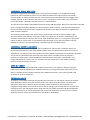
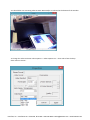
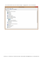
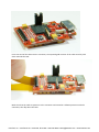
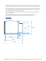
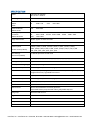
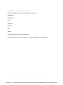
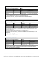
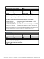
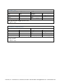
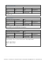
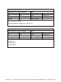
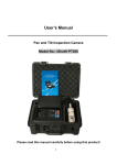
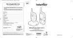
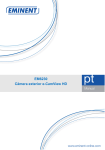
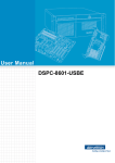
h^Ͳϯ͘Ϭ͘dECHNICAL MANUAL
Revision
V1.0
Date
Details
12/05/2014 Draft
Authorised
InterTest, Inc. • 303 Route 94 • Columbia, NJ 07832 • 908-496-8008 • [email protected] • www.intertest.com
Contents
DESCRIPTION ........................................................................................................................................ 4
INPUTS .................................................................................................................................................. 4
RECOMMENDED MINIMUM HARDWARE ............................................................................................ 4
UNIVERSAL SERIAL BUS (USB) .............................................................................................................. 5
UNIVERSAL VIDEO CLASS (UVC) ........................................................................................................... 5
USB3.0 / USB2.0 ................................................................................................................................... 5
EXTENSION UNITS ................................................................................................................................ 5
APPLICATION PROGRAMMING ............................................................................................................ 6
eCAMview VIEWER APPLICATION........................................................................................................ 6
DRIVERS .............................................................................................................................................. 10
VENDOR IDENTIFICATION (VID) ......................................................................................................... 12
CABLES ................................................................................................................................................ 13
MOUNTING ........................................................................................................................................ 17
POWER ............................................................................................................................................... 17
TEST HEADER ...................................................................................................................................... 17
FIRMWARE UPDATES ......................................................................................................................... 17
DIMENSIONS ...................................................................................................................................... 18
SPECIFICATION ................................................................................................................................... 20
APPENDIX 1 – Standard UVC Controls ................................................................................................ 22
APPENDIX 2 - Extension Unit Controls ................................................................................................ 23
EX_EXPOSURE_MODE ..................................................................................................................... 23
EX_EV_CORRECTION ....................................................................................................................... 23
EX_EXPOSURE_WEIGHTING ............................................................................................................ 24
EX_EXPOSURE_SPEED ..................................................................................................................... 24
EX_ADAPTIVE_GRADATION ............................................................................................................ 24
EX_ATR_SETUP................................................................................................................................ 25
EX_HORIZ_FLIP................................................................................................................................ 25
EX_VERT_FLIP ................................................................................................................................. 26
EX_IMAGE_STABILISATION ............................................................................................................. 26
EX_SHUTTER_SPEED ....................................................................................................................... 27
EX_GAIN .......................................................................................................................................... 27
EX_AUTO_FOCUS ............................................................................................................................ 28
EX_MANUAL_FOCUS ....................................................................................................................... 28
InterTest, Inc. • 303 Route 94 • Columbia, NJ 07832 • 908-496-8008 • [email protected] • www.intertest.com
EX_FACE_DETECTION ...................................................................................................................... 29
EX_NUM_FACES .............................................................................................................................. 29
EX_FACE_INFO ................................................................................................................................ 29
EX_WHITE_BALANCE ...................................................................................................................... 30
EX_CC_OFFSET ................................................................................................................................ 30
EX_CC_OFFSET_SETUP .................................................................................................................... 31
EX_CC_SPEED .................................................................................................................................. 31
GLOSSARY ........................................................................................................................................... 32
References
InterTest, Inc. • 303 Route 94 • Columbia, NJ 07832 • 908-496-8008 • [email protected] • www.intertest.com
User Manual
DESCRIPTION
The iShot®.USB.3.0 board is an interface for the SONY FCB-MA130 camera module. It connects the
camera to a host PC over USB3.0.
INPUTS
The SONY FCB-MA130 camera module sends video and still image data over a 16bit parallel data
bus; in addition it uses line valid (LV) and frame valid (FV) signals and sends an 81MHz pixel clock
signal.
To control the various camera settings and functions an I2C bus is used. Both the standard CMOS
Parallel Camera interface and the I2C bus are connected via an FFC cable to the iShot®.USB.3.0 board.
These signals connect to the USB controller device.
The camera module also supports a MIPI interface as an alternative to sending the video data, this is
not used by the..iShot®.USB.3.0 board.
The controller has a DMA (direct memory access) channel from the parallel input bus to the USB
block. This allows it to transfer data at a high rate. If for some reason the host PC cannot read the
data quickly enough the frame will be lost. This depends on the capacity and load on the host PC USB
controller and the host PC processor load.
The maximum video resolution is 1920 x 1080 @ 30fps. For each pixel in each frame there are two
bytes of information one for colour and one for brightness. This equates to approximately 1
Gbits/sec. The USB3.0 bus is capable of transferring up to 5Gbit/s. This will be shared across all
devices routed through the same host PC USB3.0 controller chip set – it does not mean you can get
5Gbits/sec from each physical port on the PC. Also when you have more than one device on the bus,
the total bandwidth will be reduced due to arbitration between the devices. The combination of the
FCB-MA130 and the Vreo Unity board has not been evaluated for multiple devices on the same
USB3.0 bus.
RECOMMENDED MINIMUM HARDWARE
Windows 7 or Windows 8.x
Intel i5 processor
8GB Ram
InterTest, Inc. • 303 Route 94 • Columbia, NJ 07832 • 908-496-8008 • [email protected] • www.intertest.com
UNIVERSAL SERIAL BUS (USB)
The USB is configured to use Endpoint 0 as a control channel. Endpoint 1 is configured as a bulk
transfer for video. The bulk transfer is sent in 1024 byte packets each with a 12 byte UVC header.
The UVC header is used to indicate the start of frame and end of frame data and it also toggles a bit
between packets. It also indicates if the data is from a still image or from a video frame. The format
of the UVC header is defined in the UVC version 1.5 documentation.
The firmware on the iShot®.USB.3.0 Board contains all the USB descriptors. When first connected to the USB
there is a negotiation phase between the host PC and the iShot®.USB.3.0. In this phase the descriptors
are used to tell the host PC what the capabilities of the device are. What resolutions its supports and
what controls it supports.
The communication between the devices uses a small number of control requests. INFO, Length,
GET, SET, Default, Max and Min. Using these requests the driver on the host PC can determine the
maximum and minimum values for the control, what the default value is, if it can get the value of the
control as well as set the value, it can also determine the length of any data that needs to be sent
between the devices. This communication is handled by generic windows drivers.
UNIVERSAL VIDEO CLASS (UVC)
Universal Video Class (UVC) is a specific class of products for USB, just like a computer mouse is a
Human Interface Device or HID. A UVC device handles video data and common camera controls in a
defined way. It is defined in the UVC standard. The iShot®.USB.3.0 implements this standard in firmware
and as such it is possible to view and control the camera from a number of host PC programs.
However not all functions of the FCB-MA130 are standard UVC commands. Face detection and
image stabilisation for instance are not covered in the UVC standard. For non-standard controls,
extension units (see below) are used.
USB3.0 / USB2.0
USB3.0 allows for increased bandwidths of data transmission. It can support 5 Gbits/sec whereas
USB2.0 only supports 480 Mbits/sec. USB3.0 enables the use of high resolution video cameras over
USB. It is possible to use the iShot®.USB.3.0 with a USB2.0 connection. In this case only 680 x 420
resolution at 15 fps is supported.
EXTENSION UNITS
To allow for non-standard controls UVC provides the extension unit. This allows a device to describe
what additional controls it has and how they work. This is done using descriptors in the firmware
which state how many extension controls there are. When the device is connected there is a
negotiation stage where the low level drivers for the OS will query these extension unit controls and
find out the min, max and default values along with the size of data expected to be passed between
the device and the PC. A host PC application that is aware of what these controls are can use these
additional controls. Please see the Extension Unit details in APPENDIX 2.
InterTest, Inc. • 303 Route 94 • Columbia, NJ 07832 • 908-496-8008 • [email protected] • www.intertest.com
APPLICATION PROGRAMMING
Both the directshow api and the .net framework provide functions that expose the various pins of
the device and allow you to write a custom application to control the camera and view the
streaming video or image data. The low level driver handles USB endpoints and
enumeration/negotiation.
To access the extension units you can use the Microsoft COM interface and the IksControl methods.
For further background information especially for those wanting to develop their on host software
the following documents and resources are recommended.
USB Serial Bus Specification 3.1 : Available from USB.org
UVC 1.5 Class Specification : Available from USB.org
SONY: FCB Micro - Application Note
SONY: FCB Micro User Interface Command / Event Specifications
SONY: FCB Micro User Interface Supplementary Registers Specification
MSDN see section USB Video Class Driver.
eCAMview VIEWER APPLICATION
To demonstrate the iShot®.USB.3.0 board we supply the eCAMview Application. This has implemented
the standard UVC controls. (Coming soon is the OneView application that implements the functions
provided by the extension unit).
To install the viewer extract the files from the zip file to your preferred location.
Make sure that your computer is connected to the internet, if necessary it will install the generic
windows driver from the internet.
Plug in the iShot®.USB.3.0/ FCB MA130 into a USB3.0 port.
Run the eCAMview application and then select Devices -> FX3 .
InterTest, Inc. • 303 Route 94 • Columbia, NJ 07832 • 908-496-8008 • [email protected] • www.intertest.com
You should then see streaming video at 640 x 480 at 30fps as indicated in the bottom of the window.
To change the video resolution select Options -> Video Capture Pin -> then select from the drop
down menu as shown :
InterTest, Inc. • 303 Route 94 • Columbia, NJ 07832 • 908-496-8008 • [email protected] • www.intertest.com
You should then change back to the streaming video and see the newly selected resolution.
To change image settings such as brightness, hue and saturation select Options -> Video Capture
Filter and adjust the slider settings.
The zoom function can be accessed via the camera control tab in the window shown above.
InterTest, Inc. • 303 Route 94 • Columbia, NJ 07832 • 908-496-8008 • [email protected] • www.intertest.com
Click default then adjust the slider.
To set the resolution for high resolution still images click Options -> Still Capture Pin then select from
the drop down menu:
Click apply then OK.
InterTest, Inc. • 303 Route 94 • Columbia, NJ 07832 • 908-496-8008 • [email protected] • www.intertest.com
To set the path for saving the still images select Capture -> Still Image Path :
Browse to the required location and click OK.
To take a still image select Capture -> Get Still(Enter)
The Extension units are not implemented in the eCAMview application. Coming soon is the .viewer
application which accesses the other functions available on the FCB-MA130 via the extension units.
As it is a UVC compliant device any UVC compliant viewer application can be used for the standard
UVC controls and video display. AmCap by Noel Danjou is worth considering as it is free to download
although check the conditions for commercial use. Its main advantage at this present time is that it
can record the video raw or compressed. Follow the link below and click on Freeware / Shareware.
http://noeld.com/
It will however not give access to the extension units.
DRIVERS
As the device uses the established UVC standard it does not require a custom driver and a windows
generic USB driver can be used. It may need to be installed when you first connect the device –
windows will search for the appropriate driver on line.
The device should connect as an imaging device in device manager with the following drivers.
c:\windows\system32\drivers\ksthunk.sys
c:\windows\system32\drivers\usbvideo.sys
InterTest, Inc. • 303 Route 94 • Columbia, NJ 07832 • 908-496-8008 • [email protected] • www.intertest.com
You can check that this is the case in device manager -> imaging devices -> FX3 -> driver details
InterTest, Inc. • 303 Route 94 • Columbia, NJ 07832 • 908-496-8008 • [email protected] • www.intertest.com
VENDOR IDENTIFICATION (VID)
Wesupply the iShot®.USB.3.0board with its own Vendor Identification number (VID) and product
identification number (PID). This means that when it connects to the PC it should be recognised as our
product. It is possible for larger volumes for Vreo to supply with a custom VID and PID. There is
a one off fee to arrange this. You must also already have you own VID assigned by USB.org. Contact
your distributor for more details.
InterTest, Inc. • 303 Route 94 • Columbia, NJ 07832 • 908-496-8008 • [email protected] • www.intertest.com
CABLES
There is a 45 way 0.3mm pitch FFC Jumper cable required between the camera module and the iShot®.USB.3.0
board.
One such cable is the 15015-0245 from Molex.
At the top of the image above you will see the exposed gold contacts at the ends of the cable.
These must face down when inserted into the connectors of the iShot® USB 3.0 board and the SONY
FCB-MA130 camera modules:
-+
To connect the FFC cable to the iShot®.USB.3.0 board lift the flap of P1 the FFC connector as shown
below:
InterTest, Inc. • 303 Route 94 • Columbia, NJ 07832 • 908-496-8008 • [email protected] • www.intertest.com
Insert one end of the cable into the connector, the exposed gold contacts of the cable need to point
down towards the PCB.
Make sure that the cable is square on to the connector and seated in a definite position inside the
connector; then flip down the latch.
InterTest, Inc. • 303 Route 94 • Columbia, NJ 07832 • 908-496-8008 • [email protected] • www.intertest.com
In a similar manner connect the other end to the SONY FCB-MA130 camera module, make sure the
exposed contacts face down towards the PCB.
WARNING
These types of connectors are not designed for many cycles of insertion and removal. It is best to fit
these and not remove them.
WARNING
Do not touch the exposed gold contacts on the cable or the contacts of the connector. This can lead
to longer term reliability issues if grease and dirt contaminate these surfaces.
A USB3.0 cable is required to connect the iShot®.USB.3.0 board to the host PC.
USB3.0 Type A male connector to USB3.0 Micro-B male plug is required.
InterTest, Inc. • 303 Route 94 • Columbia, NJ 07832 • 908-496-8008 • [email protected] • www.intertest.com
Figure 1 - USB3.0 Type A Male Connector
Figure 2 - USB3.0 Micro B Male Plug
Connect the Micro B end to the iShot®.USB.3.0 board:
The Type A connector should be connected to a USB3.0 port on the host PC.
Figure 3 - USB3.0 Connectors on Host PC
InterTest, Inc. • 303 Route 94 • Columbia, NJ 07832 • 908-496-8008 • [email protected] • www.intertest.com
MOUNTING
To mount the iShot®.USB.3.0 board you can use the four mounting holes with 1.6mm threaded machine
screws with a 2.8mm head size. Such as BIVAR 739.
A minimum of 4mm height spacers should be used with an outside diameter of less than3.5mm and
an internal diameter to match the screw.
One such spacer is 937-4MM from BIVAR. It is available from MOUSER part number 749-936-4MM.
WARNING
Do not screw the board down without using spacers, do not rely on the PCB components to offset
the board.
WARNING
Make sure the board is screwed down equally – i.e. do not subject the PCB to twisting or bending
forces.
InterTest makes no claim to the suitability of the mounting method to your specific application or
vibration requirements.
To mount the camera please refer to the SONY technical information. There are a lot of elements to
how it is mounted. For further information and queries regarding mounting of the camera please
seek assistance from your SONY distributor.
WARNING
The camera must have some heat dissipation plate. It can be tempting to run the camera without
such a plate but after it has warmed up, reliability can be compromised and frame rates may drop.
POWER
The iShot®.USB.3.0 interface draws its power from the USB bus. It uses 5 volts and draws a maximum of
500mA. Typical = 300mA.
The board has a 2A fuse as the first element onto the board and is there to protect the host PC in the
event of a short circuit or over current situation on the board. In normal operation this should never
blow.
TEST HEADER
A 4 pin header for factory test is located on the PCB, this is used to send debug messages over
RS232. It is not intended for customer use.
FIRMWARE UPDATES
A jumper link is fitted in normal operation. This link is used during manufacture to allow
programming the firmware on to the flash memory. In normal operation it should not be removed.
InterTest, Inc. • 303 Route 94 • Columbia, NJ 07832 • 908-496-8008 • [email protected] • www.intertest.com
If a firmware update is available removing this jumper link forces the board to boot from USB and
the bootloader will be activated. To perform the software update use the Control Centre application.
Click on the ‘bootloader’ in the left pane and then select the program menu. Select SPI. There is then
a two step process. First we program the SPI flash bootloader. Then select the firmware update file
you have downloaded / received. Program the device.
Disconnect the USB3.0 cable. Fit the jumper link. When you re-connect the Unity board will boot
with the new firmware.
If you have registered with InterTest.you will be sent information regarding firmware and
software updates. Software updates refers to the viewer demonstration program.
DIMENSIONS
4x 1.7mm DIA holes
21.0mm
17.4mm
25.0mm
6.0mm
24.0mm
8.0mm
32.0mm
34.0mm
InterTest, Inc. • 303 Route 94 • Columbia, NJ 07832 • 908-496-8008 • [email protected] • www.intertest.com
Four 1.7mm mounting holes are provided, these are intended for 1.6mm screws.
InterTest, Inc. • 303 Route 94 • Columbia, NJ 07832 • 908-496-8008 • [email protected] • www.intertest.com
SPECIFICATION
Power
Powered from USB bus
Max current = 500mA
Operating Temperature
0 to +50°C
Video Resolution
USB3.0
30FPS
Full HD 1920 x 1080
HD
1280 x 720
Video Resolution
USB2.0 15FPS
VGA
640 x 480
Still Image Capture
Resolution
USB3.0 Method 2
13M
5M
SXGA
4192 x 3104 12M
4128 x 3096
2592 x 1944 Full HD 1920 x 1080
1280 x 960
Image Stabilisation
ON/OFF applies to video and stills
Exposure Modes
Auto, Hold, Shutter Priority, Gain Priority
Shutter Speed
1/5000, 1/4000, 1/3000, 1/2500, 1/2000, 1/1500, 1/1250, 1/1000,
1/800, 1/600, 1/500, 1/400, 1/300, 1/250, 1/200, 1/150, 1/120, 1/100
1/80, 1/60, 1/50, 1/40, 1/30, 1/25, 1/20
(Shutter Priority Mode)
UXGA 1600 x 1200
VGA
640 x 480
SXGA
8M
UXGA
1280 x 960
3264 x 2448
1600 x 1200
Gain Settings
(Gain Priority Mode)
1 to 65535 equivalent to ISO value
EV Correction
-6/3, -5/3, -4/3, -3/3, -2/3, -1/3, 0, 1/3, 2/3, 3/3, 4/3, 5/3, 6/3
Back Light Compensation
ON/OFF
Auto Exposure Weighting Centre, Spot, Average
Auto Exposure Speed
Sets convergence speed : normal, high, low
White Balance Mode
Auto, Hold, All pull in, Light Bulb, Neutral Fluorescent, Clear Sky, Cloudy Sky,
Daylight Fluorescent, Light Bulb Fluorescent
White Balance Offset
ON/OFF, Red Offset, Blue Offset
White Balance Speed
Sets convergence speed : normal, high, low
Flicker
Off, Auto, 50Hz, 60Hz, 50Hz -> Auto, 60Hz -> Auto
Autofocus
Contrast method
Manual focus
Move to the fixed Macro or Infinity positions.
Step towards Macro, Step towards infinity, Adjustable Step size
Image Flip
Horizontal and vertical
Brightness
0 to 15
Contrast
-8 to +8
Sharpness
-8 to +8
Hue
-30° to +30°
InterTest, Inc. • 303 Route 94 • Columbia, NJ 07832 • 908-496-8008 • [email protected] • www.intertest.com
Color Gain
-32 to +32
Zoom
Digital zoom x1 to x16
Face Detection
On/Off, #faces. Reports X & Y position, size and rotation angle for max 8 faces.
Test chart
On/Off
InterTest, Inc. • 303 Route 94 • Columbia, NJ 07832 • 908-496-8008 • [email protected] • www.intertest.com
APPENDIX 1 – Standard UVC Controls
Controls Implemented as standard UVC controls.
Brightness
Sharpness
Hue
Contrast
Flicker
BLC
Zoom
Still capture method 2 is supported.
Video resolution and still capture resolution change are supported.
InterTest, Inc. • 303 Route 94 • Columbia, NJ 07832 • 908-496-8008 • [email protected] • www.intertest.com
APPENDIX 2 - Extension Unit Controls
EX_EXPOSURE_MODE
Extension Unit Control Number
0x01
Get
Yes
Length
1
Set
Yes
Type
Unsigned Int
Max
4
Min
0
Default
0
Camera CMD
CM_AE_MODE
This extension unit control is used to change exposure mode.
The control expects an unsigned int in the range 0 to 4.
It effectively calls the CM_AE_MODE command with the received byte as the
parameter.
0 = Auto, 1 = Hold, 2 = Manual, 3 = Shutter Priority, 4 = ISO (gain) Priority
EX_EV_CORRECTION
Extension Unit Control Number 0x02
Get
Yes
Length
1
Set
Yes
Type
Signed Int
Max
+6
Min
-6
Default
0
Camera CMD
CM_AE_EV_CORRECTION
This extension unit control is used to change EV Correction level.
The control expects a Signed int in the range -6 to +6.
-6 equates to -6/3 in real life and each step is 1/3 so the GUI needs to
present a selection of -6/3, -5/3 ……0 ……+5/3, 6/3.
It effectively calls the CM_AE_EV_CORRECTION command with the received
byte as the parameter.
InterTest, Inc. • 303 Route 94 • Columbia, NJ 07832 • 908-496-8008 • [email protected] • www.intertest.com
EX_EXPOSURE_WEIGHTING
Extension Unit Control Number
0x03
Get
Yes
Length
1
Set
Yes
Type
Unsigned Int
Max
2
Min
0
Default
0
Camera CMD
CM_AE_PHOTOMETRY
This extension unit sets the exposure weighting or metering.
0 = Centre Weighted, 1 = Spot, 2 = Average Weighting.
It effectively calls CM_AE_PHOTOMETRY with the received byte.
EX_EXPOSURE_SPEED
Extension Unit Control Number
0x04
Get
Yes
Length
1
Set
Yes
Type
Unsigned Int
Max
+2
Min
0
Default
0
Camera CMD
CM_AE_SPEED
This extension unit control is used to set the convergence speed of the auto
exposure algorithm.
The control expects an unsigned int in the range 0 to +2 .
It effectively calls the CM_AE_SPEED command with the received byte as the
parameter.
0 = Normal, 1 = High, 2 = Low
EX_ADAPTIVE_GRADATION
Extension Unit Control Number
0x05
Get
Yes
Length
1
Set
Yes
Type
Unsigned Int
Max
1
Min
0
Default
0
Camera CMD
CM_ATR
This extension unit control is used to turn on or off the adaptive gradation
correction which can be used to extend the dynamic range of the camera.
It calls CM_ATR camera command.
InterTest, Inc. • 303 Route 94 • Columbia, NJ 07832 • 908-496-8008 • [email protected] • www.intertest.com
EX_ATR_SETUP
Extension Unit Control Number
0x06
Get
Yes
Length
4
Set
Yes
Type
Unsigned Int
Max
Min
Default
0
Camera CMD
N/A
This extension unit control is used to write all 4 supplementary registers
associated with the adaptive gradation correction / wide dynamic range.
A 4 byte unsigned integer array is expected.
The register addresses and the relevant parameters written to are :
0x120B ATR_GAIN
0x120C ATR_WIDE_D
0x120D ATR_CONTRAST
0x120E ATR_CHROMA
How much of the ATR effect to apply. 0 - 255
0 = Off, 1 = ON
0 = AUTO, Low = more contrast, High = more WDR
The higher the number, the higher the chroma.
Using this control only sets the relevant supplementary registers to have any
effect you should then use the EX_ADAPTIVE_GRADATION control.
EX_HORIZ_FLIP
Extension Unit Control Number
0x07
Get
Yes
Length
Set
Yes
Type
Max
1
Min
Default
0
Camera CMD
Sets the horizontal image flip on or off.
Applies to both video and still images.
Processing is performed on the camera.
0 = off. 1 = on
1
Unsigned Int
0
InterTest, Inc. • 303 Route 94 • Columbia, NJ 07832 • 908-496-8008 • [email protected] • www.intertest.com
EX_VERT_FLIP
Extension Unit Control Number
Get
Yes
Set
Yes
Max
1
Default
0
Sets the vertical image flip on or off.
0 = off. 1 = on
0x08
Length
Type
Min
Camera CMD
1
Unsigned Int
0
EX_IMAGE_STABILISATION
Extension Unit Control Number
0x09
Get
Yes
Length
1
Set
Yes
Type
Unsigned Int
Max
1
Min
0
Default
0
Camera CMD
Sets the image stabilisation on or off. It is applied to both video and still
image modes.
0 = off. 1 = on
InterTest, Inc. • 303 Route 94 • Columbia, NJ 07832 • 908-496-8008 • [email protected] • www.intertest.com
EX_SHUTTER_SPEED
Extension Unit Control Number
0x0A
Get
Yes
Length
1
Set
Yes
Type
Unsigned Int
Max
38
Min
1
Default
31
Camera CMD
Sets the supplementary register AE_SHUTTER on the camera.
Only has any effect when you issue a EX_EXPOSURE_MODE with Shutter
Priority.
Values 1 to 38 correspond to real world exposures as per the following table.
1
2
3
4
5
6
7
8
9
10
Time
(sec)
1/5000
1/4000
1/3000
1/2500
1/2000
1/1500
1/1250
1/1000
1/800
1/600
11
12
13
14
15
16
17
18
19
20
Time
(sec)
1/500
1/400
1/300
1/250
1/200
1/150
1/120
1/100
1/80
1/60
21
22
23
24
25
26
27
28
29
30
Time
(sec)
1/50
1/40
1/30
1/25
1/20
1/15
1/12
1/10
1/8
1/6
31
32
33
34
35
36
37
38
Time
(sec)
1/5
¼
1/3
0.4
0.5
0.65
0.8
1
EX_GAIN
Extension Unit Control Number
0x0B
Get
Yes
Length
2
Set
Yes
Type
Unsigned Int
Max
65535
Min
1
Default
800
Camera CMD
Sets the supplementary registers AE_ISO on the camera.
Sets the ISO sensitivity – equivalent to Gain
Only has any effect when you issue EX_EXPOSURE_MODE with ISO Priority.
InterTest, Inc. • 303 Route 94 • Columbia, NJ 07832 • 908-496-8008 • [email protected] • www.intertest.com
EX_AUTO_FOCUS
Extension Unit Control Number
0x0C
Get
Yes
Length
1
Set
Yes
Type
Unsigned Int
Max
1
Min
0
Default
0
Camera CMD
This will action a one touch auto focus sequence.
0 = normal, 1 = perform autofocus.
When the operation has finished the firmware will reset this control to 0, i.e.
a get operation will return 1 whilst the autofocus operation is happening and
0 when it has finished.
This is a one shot action.
EX_MANUAL_FOCUS
Extension Unit Control Number
Get
Yes
Set
Yes
Max
See below
Default
0
0x0D
Length
Type
Min
Camera CMD
1
Unsigned Int
See below
Bits 7:6 sets the mode
00 = Move to infinity position
01 = Move towards the infinity position
10 = Move to Macro position
11 = Move towards macro position
Bits 5:0 set the step size for modes 1 and 3.
We will set this to either 1, 2 or 3 in the OneView Application.
InterTest, Inc. • 303 Route 94 • Columbia, NJ 07832 • 908-496-8008 • [email protected] • www.intertest.com
EX_FACE_DETECTION
Extension Unit Control Number
0x0E
Get
Yes
Length
Set
Yes
Type
Max
1
Min
Default
0
Camera CMD
This enables the face detection function.
0 = off, 1 = on.
EX_NUM_FACES
Extension Unit Control Number
0x0F
Get
Yes
Length
Set
Yes
Type
Max
8
Min
Default
8
Camera CMD
Sets the supplementary register for the number of faces.
Has no effect until face detection is turned on.
1
Unsigned Int
0
1
Unsigned Int
1
EX_FACE_INFO
Extension Unit Control Number
0x10
Get
Yes
Length
40
Set
No
Type
Unsigned Int
Max
Min
Default
Camera CMD
This extension control receives an array of data with the face information.
Face[i],Info[j] : i=0 to 7, j=0 to 4, Pos X, Pos Y, Size, Angle, Node.
Byte 0 = face 0, Pos X
Byte 1 = face 0, Pos Y
etc
InterTest, Inc. • 303 Route 94 • Columbia, NJ 07832 • 908-496-8008 • [email protected] • www.intertest.com
EX_WHITE_BALANCE
Extension Unit Control Number
Get
Yes
Set
Yes
Max
10
Default
0
0x11
Length
Type
Min
Camera CMD
1
Unsigned Int
0
Selects the white balance mode as per the table below.
0
1
2
3
4
5
6
7,8
9
10
Mode
Auto
Hold
ATW
Light bulb
Neutral colour fluorescent light
Clear sky
Cloudy sky
Setting prohibited
Daylight colour fluorescent
Light bulb colour fluorescent light
EX_CC_OFFSET
Extension Unit Control Number
0x12
Get
No
Length
1
Set
Yes
Type
Unsigned Int
Max
1
Min
0
Default
0
Camera CMD
Colour correction, white balance, gain offset. 0 = off, 1 = on.
InterTest, Inc. • 303 Route 94 • Columbia, NJ 07832 • 908-496-8008 • [email protected] • www.intertest.com
EX_CC_OFFSET_SETUP
Extension Unit Control Number
0x13
Get
Yes
Length
2
Set
Yes
Type
Signed Ints
Max
Min
Default
0
Camera CMD
Sets the camera supplementary registers: CC_R_OFFSET and CC_B_OFFSET.
Also see EX_CC_OFFSET.
The values of each range from -128 to 127.
EX_CC_SPEED
Extension Unit Control Number
0x14
Get
Yes
Length
Set
Yes
Type
Max
2
Min
Default
0
Camera CMD
Sets the white balance convergence speed.
0=Normal
1=High Speed
2=Low Speed
1
Unsigned Int
0
InterTest, Inc. • 303 Route 94 • Columbia, NJ 07832 • 908-496-8008 • [email protected] • www.intertest.com
GLOSSARY
Firmware: This refers to the software that runs on the controller chip on the PCB.
Software: Refers to the Viewer application.
InterTest, Inc. • 303 Route 94 • Columbia, NJ 07832 • 908-496-8008 • [email protected] • www.intertest.com