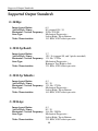
1
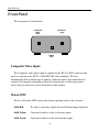
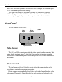
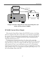
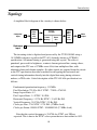
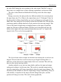
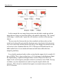
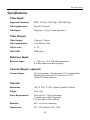
Standards Converter
for
Mechanical Television
Model’s SCM
User and Technical
Manual
Copyright 2006-12 Aurora Design LLC.
Revision 4.0
2 October, 2012
All specifications subject to change
www.tech-retro.com
Introduction
Introduction
This manual covers the operation and technical aspects of the Single-Standard
Converter for mechanical television. The Converter is designed to accept an NTSC
or PAL/SECAM video signal and convert to one of several different output
standards. The converted video is sent to a composite video output connector.
Due to the nature of mechanical television it is assume that the user has a good
understanding of what is required to operate such a device in conjunction with this
converter, such as an appropriate lamp (Neon, LED, etc.) and a lamp driver that
accepts the video output signal from this converter. No attempt is made in this
document to describe such a driver and it’s operation.
Features
• Compact, low power, surface mount design
• Front panel tri-color Status LED
• Up to 16 user programmable options
• Extremely stable output: +/- 3% levels
• 10 bit video D/A for greater than 54dB dynamic range
• 250K gate equivalent FieldProgrammableGateArray
• 8Mb FLASH memory for FPGA firmware, user parameters and default image
• Automatic Sleep Mode for low power standby operation
• Reference Input allows synchronization to external source
• Extremely accurate algorithms used for conversions
• Full three frame memory for stable output regardless of input
• Versatile I/O:
- Composite Video Input (NTSC/PAL, 1Vpp, 75 ohm)
- Video Output (various standards, 1Vpp, 75 ohm)
- Reference Input (+/-30V, 20K ohm, ZeroCrossingDetector)
- Current Driver Output (333ma maximum) (optional)
- DC power (7-14Vdc, 200ma)
3
Introduction
Front Panel
The front panel is shown below:
Composite
Video
Input
Reference
Input
Status
LED
Composite Video Input:
The Composite video input signal is supplied to this RCA or BNC connector and
needs to conform to the NTSC or PAL/SECAM video standards. The unit
automatically detects which type of signal is connected and no user intervention is
required. For complete information about the characteristics of this input, please
refer to the Specifications section found later in this manual.
Status LED:
The tri-color status LED conveys the current operating state of the converter.
Solid Red:
No video or reference signal detected. Default image displayed.
Solid Yellow:
Converter locked to video or reference input.
Solid Green:
Converter locked to video and reference input.
4
Introduction
Slow Flashing:
Options setting mode.
Red:
Option Disabled
Green:
Option Enabled
Yellow:
Option Not Available
Pulsating Red:
Converter in low power Sleep mode.
Fast Flashing:
Converter Storing default image to internal FLASH.
Yellow or Green
Alternating: Thermal overload on optional Current Driver output.
Red and Green:
Reference Input:
The Reference Input is required for use with certain standards, but is available on
all standards. There were two main methods of synchronization used in early
mechanical television, one filtered a portion of the video signal and fed it to phonic
coils on the television. This method was used when viewing over great distances
since the transmitter and receiver where not expected to be on the same AC Mains
grid. The other method assumed the AC motor at the transmitter and receiver where
powered by the same AC Mains grid, so were inherently in sync. It is for this type of
setup the Reference input is mainly used.
One of three different frequencies can be used with all standards; a 50Hz Mains
reference, a 60Hz Mains reference, or a frame reference. The frame reference must
correspond to the frequency for the selected standard as shown in the Appendix:
Support Output Standards. For instance, the 45/15-3i Western standard will only
accept a 15 Hz frame reference pulse in addition to the two Mains frequencies. The
supplied signal to this input must be within +/-4% of the shown value or the unit
will not lock to it. The input is an edge sensitive, zero crossing detector, so the actual
shape of the signal is irrelevant as long as the selected edge to edge timing is fairly
stable. The converter will filter out high band noise, but low, in band frequencies
may cause the converter to “hunt”, with the typical back and forth motion of the
image. If this occurs, either a cleaner reference signal is required, or the user can
change the Reference Fast Tracking option discussed later. The polarity of the edge
5
Introduction
used is also selectable by the user as discussed later. The input can withstand up to a
+/-30V maximum signal without damage.
This signal will usually be provided by a small AC transformer, typically
6-12Vac, plugged into the same Mains outlet as the television, or from a frame
reference signal supplied by some modern experimental mechanical televisions.
Rear Panel
The rear panel is shown below:
Video
Output
Current
Driver
(Optional)
Selector Switch
Options Button
7-14Vdc
Input
Aux Button
Video Output:
This RCA or BNC connector provides the video output from the converter. This
output should terminate into a 75 ohm load. For complete information about the
characteristics of this output, please refer to the Specifications section found later in
this manual.
Selector Switch:
The dual purpose Selector Switch is used to select the output standard and to
select the user option during options programing.
During normal operation, the Selector Switch selects the Output Standard of the
video output. The specific Output Standard for each position can be found on the
6
Introduction
bottom label of the converter, and in the Supported Output Standards section found
later in this manual. This control is adjusted by inserting a small flat blade or phillips
screw driver into the hole, and engaging the slots in the switch.
If the Option Button is pressed (see below), the current Output Standard is
frozen, and the Selector Switch is used to select the desired user programable option.
Options Button:
This pushbutton is used to enter the Options Setting Mode and to change the state
of the User Options. The button can be depressed by inserting a paper clip, or other
small tool into the hole in the back of the unit. When the Option Button is depressed
for 1 second, the unit enters the Option Setting Mode and freezes the currently
selected Output Standard. By using the Selector Switch, you can choose the desired
option position. The front panel Status LED will blink green if the option is enabled,
red if the option is disabled, and yellow if the option is not supported. When the
desired User Option is chosen using the Selector Switch, the Option Button is
pressed momentarily to toggle the option between enabled and disabled. Each option
can be programmed in this manner. When finished, the Option Button is once again
depressed for 1 second to exit the Option Setting Mode. Also if no changes of the
Selector Switch or Option Button are detected for 1 minute, the unit will
automatically exit the Options Setting Mode and return to normal operation.
When the unit returns the normal operation, the Selector Switch may need to be
returned to the desired Output Standard.
Current Driver (optional):
This connector provides a Current Driver output from the converter. This output
is suitable for direct connection to an LED lamp such as the NEL-1M. It is thermally
and short circuit protected. If the output does go into thermal overload, the front
panel Status LED will indicate this, and the unit will return to normal operation once
the temperature has returned to an acceptable level. For complete information about
the characteristics of this output, please refer to the Specifications section found later
in this manual.
7
Introduction
Auxiliary Button:
The Auxiliary Button is used to frame the image on the television and to store the
user default image.
While most mechanical televisions provide some means to align the scan lines,
many do not offer such ability for frame alignment. By momentarily depressing this
button, the image will move down by one line. By holding this button down for 1/2
seconds, the image will move up by one line.
To store a default image the converter must be in it’s normal operating mode,
with a valid video input connected, and a solid yellow or green Status LED. If a
valid video input is not connected, an image cannot be stored. With a stable,
stationary video input applied, the Auxiliary Button may be pressed and held for 4
seconds. The Status LED will begin to flash yellow or green quickly, indicating
storing of the image FLASH is taking place. This process can take up to 10 seconds,
and the video signal must not be disturbed during this process. After the image is
stored, the Status LED will return to solid yellow or green.
Once an image is stored, whenever there is no video input connected to the unit,
the default image stored in the FLASH may be outputted. (user option to select
between this image and the built-in test pattern)
Caution! Because of the nature of the partial-field memory contained in this unit,
the default image is stored in bands of several lines at a time. If the connected video
is not stationary during the storing process, the resulting image will be distorted. The
best way to provide a stationary image for storing is to use the output from a
computer video card, or a DVD/PVR player in pause. A typical VCR without a TBC
in pause is not suitable for this use.
Power:
The converter requires a power source of between 7.0 and 14 volts DC at 200
mA. A 9 volt DC power supply is recommended to reduce power consumption.
(12Vdc is recommended when driving a NEL-1M lamp from the optional Current
Driver) Voltages over 16 volts will damage the unit. The unit has a reverse polarity
diode in series with the input, so it will not be damaged by reversal of polarity. The
8
Introduction
unit uses a standard 2.1mm X 5.5mm, center positive, coaxial power connector as
found on most consumer electronic equipment.
User Options
As previously outlined, using a small tool such as a paper clip, carefully press the
Options Button for 1 second. This will place the unit into the Options Setting Mode.
Next choose the desired option using the Selector Switch. The front panel Status
LED will blink green if the option is enabled, red if it is disabled, and yellow if not
supported. To change the state of the option, momentarily depress the Options
Button to toggle between enabled and disabled. When all desired options are set,
again depress the Option Button for 1 second to exit the Options Setting Mode. Also
the unit will automatically return to normal operation if the Selector Switch and
Option Button are not changed for 1 minute.
Note: Be sure to return the Selector Switch to the desired Output Standard setting
after changing the User Options.
Position 0 - Sleep:
This option is used to disable the automatic Sleep Mode. When Enabled the
Sleep Mode will force the unit and it’s output into a low power state if no video
input is detected for 1 hour. When Disabled the unit will never go to sleep.
Position 1 - Gamma
This option is used to select the output mode of the converter between gamma
corrected and straight video. Since modern video is pre-corrected at the source to
compensate for the gamma of CRT’s, and since most lamps used for mechanical
television are linear (Neon, LED, etc.) gamma correction needs to be provided to
correct the video. This feature performs the correction accurately in the converter so
it is not required in the lamp driver. When Enabled, gamma correction will be added
to the output. When Disabled straight video will be output, and gamma correction
will need to be provided externally. This option should normally be set to Enabled.
9
Introduction
Position 2 - Invert
This option is used to select the output mode of the converter between normal
and inverted. When Disabled the converter will output a positive video signal. When
Enabled the converter will invert the output. This can be useful to match the polarity
of an external lamp driver. This option should normally be set to Disabled.
Position 3 - Default Image Select
This option is used to select the default image that is displayed when no video
input is present. When Disabled the built-in test pattern is displayed. When Enabled
the user stored image is displayed. (Note: the unit is shipped with no user default
image stored)
Position 4 - Edge Rate Control:
This option is used to control the Edge Rate of the output video. Since modern
electronics are capable of extremely high frequency operation, and all of these early
mechanical formats were of very low bandwidth, this option can better match the
output bandwidth to that of the Output Standard. When Enabled, this option will
control the Edge Rate of the Video Output to limit it’s bandwidth to that of just
higher than the Output Standard. When Disabled, no limiting is performed on the
Video Output, and it will contain extremely high frequencies. This option should
normally be set to Enabled.
Position 5 - Frame Buffer Count:
This option is used to select between 3 frame buffers and 1 frame buffer. When
Enable, three frame buffers will be used. In this mode the output video image will
always be complete, but fast motion in the video may be jerky or not smooth do to
the difference in frame rates between the input video and output video. When
Disabled only one frame buffer is used which will provide smoother looking images
10
Introduction
in the output, but images that may have tearing on fast motion. For still or slowly
moving images both modes will look exactly the same on the output. For more
information about the this option, please refer to the Theory of Operation section
found later in this manual. This option should be put into the mode the user finds
yields the best image quality.
Position 6 - Black Level:
This option is used to control the Black Level in the output video. Some
mechanical standards like 32/12.5p NBTV have black level set at 30% with peak
white at 100%, while most other standards have black at 0% with peak white at
100%. This makes it difficult for a lamp driver since the black level and range are
different for the various standards. To eleviate this condition, this option can be
Enable which will force all standards to use 30% for black and 100% for peak white
making it easier for the lamp driver. When Disabled this option will ouput the
standards normally. This option should be set to Disabled for normal use, and must
be set to Enabled when using the optional internal Current Driver.
Position 7 - Reverse Line:
This option is used to reverse the direction of the scan lines when Enabled. For
instance the normal direction for the 45/15_31 Western is right to left, so this will
force left to right scanning. 60/20p is left to right so this will force right to left
scanning. When Disabled the scan lines will be in the normal direction for the
Output Standard. This can be useful if the television motor operates in the wrong
direction, or the viewing window is on a different part of the wheel, etc. This option
should normally be set to Disabled.
Position 8 - Reverse Frame:
This option is used to reverse the scan direction of the frames. When Enabled this
option will reverse the normal scan direction of a frame. For instance the normal
direction for the 45/15-3i Western is top to bottom, so this will force bottom to top
11
Introduction
scanning. 30/12.5 Baird is bottom to top so this will force top to bottom scanning.
When Disabled the frames will be in the normal direction for the Output Standard.
This can be useful if the television motor operates in the wrong direction, or the
viewing window is on a different part of the wheel, etc. This option should normally
be set to Disabled.
Position 9 - Reference Edge Polarity:
This option is used to control which edge the Reference Input Zero-CrossingDetector will use. When Enable, the positive going edge will used, When Disabled
the negative going edge will be used. For most applications this is not important, but
may be useful to the experimenter.
Position A - Reference Fast Tracking:
This option is used to control the loop speed of the Reference Digital-PhaseLocked-Loop used to synchronize the Video Output to the Reference Input. When
Enabled, the converter will lock faster, and track closer to the Reference Input
signal. This can be good and bad. If the Reference Input contains a lot of jitter or
other errors, the converter will more likely track those errors in this mode, and
possibly even make them worse do to overall system damping. This may result in an
image that hunts along the line direction trying to keep up with the Reference signal.
It can be useful however for the experimenter using modern electronics in there
mechanical television. When Disabled the unit will take twice as long to lock but
will provide a more damped, and more stable lock. This option should normally be
set to Disabled.
Position B - Reference Hold:
This option is used to control the behavior of the Reference Digital-PhaseLocked-Loop used to synchronize the Video Output to the Reference Input when no
reference is detected. When Enabled, the Digital-Phase-Locked-Loop will hold the
12
Introduction
last valid value until a new reference signal is detected or the output standard is
changed. When Disabled, the Digital-Phase-Locked-Loop will always return to it’s
nominal setting when no reference signal is detected. This option should normally
be set to Enabled.
Operating Modes
Normal Full Operating Mode, no Reference:
When valid video is present the Status LED will show a solid yellow light, and
the unit will output converted video on the video output connector. This mode is
appropriate for standards that didn’t originally use a Reference like the 30/12.5p
Baird or the 32/12.5p NBTV.
Normal Full Operating Mode, with Reference:
When valid video and an appropriate Reference signal are present, the Status
LED will show a solid green light, and the unit will output converted video on the
video output connector in sync with the Reference input. This mode is appropriate
for standards that used a Reference like the 45/15_3i Western format. These formats
typically used a synchronous AC motor to drive the disk, so the converter needs to
also be synchronized to the same AC mains source. For complete information about
the characteristics of this input and how to use it in a typical application, please refer
to the Typical Connections section found later in this manual.
Default Image Mode:
When no valid video is connected to the composite input, the converter will
output a default image. This can be used to verify operation of the unit, or aid in
setup of the television. The image can either be a user stored image or the built-in
test pattern. The built-in test pattern consists of an 8 step ramp on the top half of the
frame and a linear ramp on the lower half. There is also an “X” in the middle of the
13
Introduction
image to help align the image on the television, and find the correct sequence for
interlaced standards. The image appears as below:
Sleep Mode:
Since no power switch is supplied on this unit, an automatic Sleep Mode will be
entered whenever the video input is not present for more than 1 hour. With this
feature, the converter is placed into a low power mode, along with the video output
being shut off. Only the video decoder is left active to signal when a valid video
input is again supplied to the unit to wake it up.
Typical Connections
In normal usage, a user supplied power adapter is connected to the converter and
to the AC power source. A valid NTSC or PAL/SECAM video source will also be
connected to the Composite Video input. The video source can be anything from a
VCR to a DVD to an off-air broadcast. The video output can then be connected to
the input of a user supplied lamp driver, or the output of the optional internal
Current Driver can be connected directly to an LED lamp like the NEL-1M. A user
supplied driver needs to take the video output signal from the converter and power
the desired lamp. (Neon, LED, etc.). The users driver should provide for brightness
(level) and contrast (gain) controls to adjust the video signal for proper operation of
the lamp. The brightness control can be used to properly setup for blacks while the
contrast control can setup for peak whites. (this is not required on the optional
internal Current Driver as this is handled automatically)
User options like Gamma and Invert can be adjusted to match what the user
supplied lamp driver requires.
14
Introduction
Typically some means of synchronization is required for the television to avoid
having the user constantly adjust the speed and phase of the motor to keep the image
centered and phased. For the NBTV standard, this is done through the insertion of
standard type line sync pulses in the video, with the pulse missing on line one for
frame synchronization. A properly equipped NBTV television will lock to the output
of the converter with no other adjustments necessary. The line and frame phasing
should be correct every time the television is operating after initial adjustment.
For televisions like the Baird which used an AC/DC motor and a synchronous
phonic coil, the video output signal from the converter needs to be filtered and fed
through an amplifier to the phonic coils on the television. This will lock the
television to the converter but the user will still need to phase (center) the image.
For televisions that used an AC synchronous motor like the Western Visionette,
an AC Mains reference must be connected to the Reference Input on the converter so
the converter can lock to the same signal as the motor in the television. In order to
accomplish this, a standard 6-12VAC transformer can be used to feed the Reference
input. (+/-30V maximum peak) If the signal is noisy, it may be beneficial to filter the
signal with a 4.7K resistor and a 0.1uF capacitor. This will filter out much of the
high frequency noise.
For the prior two examples, the user will always have to adjust the frame and
possibly the line phase every time the television is operated. This is the nature of
these types of early mechanical television. There is normally some means provided
on the television to accomplish this phasing. Alternatively the user can use the
Auxiliary Button on the back of the converter to perform the frame phasing without
having to use the television. Each time the Auxiliary Button is momentarily
depressed the frame will jump down one line. Each time the Button is held for 1/2
seconds the frame will jump up one line.
If your television is a modern experimental unit with a frame sync output pulse,
this can be used to drive the Reference Input of the converter. With this type of
system, once the phasing is adjusted, it should never need to be readjusted, and the
television should always power up correctly phased.
Since the converter contains three full frames of video memory, the output signal
will always be stable regardless of the video input signal. Normally a mechanical
television would require relocking and rephasing each time the video input signal
changed, but the converter eliminates this entirely. Once the television is locked to
the converter, it should remain so indefinitely
15
Introduction
Due to the nature of standards conversion, frame rate conversion is extremely
difficult. This converter provides two different methods of frame rate conversion
that can be selected by the user. More can be found out in the Theory of Operation
section later in this manual.
The use of high quality video cables is recommended for best results. Cables
conforming to 75 ohm impedance should be used on the video inputs and outputs.
If all the above steps have been properly performed, there should now be a solid
yellow or green status light on the front panel of the converter indicating a locked
video signal as described previously, and a stable image on the television.
To help aid in setup, when no video input is presented to the converter, it will
output a default image. This can be useful in making final adjustments to the
television, and for phasing the television before the video input is connected.
Video content is important to consider when dealing with mechanical televisions
due to the small size and low resolution of the image. Close ups that are centered in
the video make for better viewing on the mechanical television. For standards with
low aspect ratio such as Baird (3:7) and NBTV (2:3) only the center portion of the
input video is converted to maintain the correct ratio.
Some examples of typical connections to mechanical televisions:
AC Mains
6-12Vac
To NEL-1M
Mains
Reference
Western Visionette
Example connection to Western Visionette using internal Current Driver
16
Introduction
Low pass filter
and amplifier
To Phonic Coil
Lamp Driver
To Lamp
Baird Televisor
Example connection to Baird Televisor using external lamp driver and
phonic coil filter and power amplifier
SCM-01D Current Driver Output:
When using the Current Driver Output of the SCM-01D converter, a few things
need to be considered. Since this is a linear driver, excess heat may be generated in
the converter. The unit is fully protected against thermal overload and will shut off
the output if it reaches 65°C internally, and will not return to operation until the
temperature falls back below 55°C.
To minimize heat dissipated by the driver, the voltage used to operate the
converter should be no more than 2 volts above what is required by the LED you are
using when driven at 333ma. For example, the NEL-1M requires approximately 10
volts to operate at 333ma, so you would run the converter at 12 volts maximum.
Conversely you do not want to use too low of a voltage or clipping may occur in the
output spoiling the image. It is recommended to keep the input voltage at least 1 volt
above the operating voltage of the LED.
17
Introduction
Theory of Operation
In order to convert between different video standards, spatial and temporal
correction are required. Spatial correction involves changing the resolution, size and
aspect ratio of the incoming video to the output video format. This can be easily
achieved through standard digital methods utilizing scalers and FIR filters. This will
be discussed in detail. Temporal correction involves changing the frame rate of the
incoming video to match the outgoing video.
It was decided that no off the shelf components existed that would provide the
desired functionality, so a FieldProgrammableGateArray, or FPGA, was chosen to
provide all the digital functionality. By adding input/output circuitry, and ancillary
circuitry to the FPGA, the entire system could be realized. The basic building blocks
to the design are; FPGA, video decoder (ADC), and multiple power supplies. A brief
description of each part follows:
FPGA: Xilinx XC3S250E-4VQ100
250K gate equivalent
216Kb block RAM
1.2V Core / 2.5V Aux / 3.3V I/O
Video Decoder:
TI TVP5150AM1
9bit ADC’s, 2X Over-Sampled
Line Locked Clock
4 Line Adaptive Comb Filter
Multiplexed 8bit YCrCb output bus
Video DAC:
Proprietary Design
10bit effective DAC
35 MSPS maximum conversion rate
56 dB SNRs
FLASH Memory: Winbond W25Q80BV
8Mb Serial FLASH ROM
18
Introduction
Topology
A simplified block diagram of the circuitry is shown below:
Composite
Input
Video
ADC
and
Decoder
FPGA
Frame
Memory
Video
DLL
Video
DAC,
Filter
and
Driver
Video
Output
Reference
Input
The incoming video is digitized and processed by the TVP5150AM1 using a
14.318MHz reference crystal to the ITU-601 (formerly known as CCIR601)
specification. All internal timing is generated using this crystal. The video is
quantized, processed for brightness, contrast, chroma gain and hue, among others,
and output at the ITU rate of 27MHz on an 8 bit, time multiplexed bus, with
alternating luma and chroma samples. No other signals are required from this circuit
as the ITU specification describes a method for encrypting the horizontal and
vertical timing information directly into the digital data using timing reference
makers, or TRS codes. A brief description of the ITU-601/656 specification is as
follows:
Fundamental quantization frequency: 13.5MHz
Pixel Resolution: 720 H x 486 V NTSC / 720 H x 576 PAL
Image Aspect Ratio: 4:3
Pixel Aspect Ratio: 1.1 NTSC / 0.9 PAL
Horizontal Frequency: 15,734 Hz NTSC / 15,625 Hz PAL
Vertical Frequency: 29.97 Hz NTSC / 25 Hz PAL
Clocks per Line: 1716 NTSC / 1728 PAL (27MHz clock)
Clocks per Frame: 900900 NTSC / 1080000 PAL (27 MHz clock)
Note that the vertical frequency is 29.97Hz for NTSC, not 30Hz as
expected. This is due to the NTSC color system that was first ratified in 1953.
19
Introduction
All monochrome television transmissions prior to this standard used exactly
30Hz, or 30 frames per second, so as to be in sync with the AC mains
frequency. This is done to reduce distortions in the image due to induced AC
fields or “hum” from the power supplies of these early sets. In order to devise
a “compatible” color system that would show a monochrome signal on
existing sets, RCA proposed a method of modulating the color components of
the video signal onto a subcarrier in the video. For reasons beyond the scope
of this manual, a frequency needed to be chosen so that no standing patterns
in the color signal would result. This required lowering the vertical frequency
from 30Hz to 29.97Hz. While this change caused no adverse side effects on
televisions, it has created a legacy of problems for modern video equipment.
Instead of being able to use integer numbers like 24, 25 and 30, we now have
to include 29.97 which makes many calculations and conversion extremely
difficult. For digital processing, the ratio 1000/1001 has been established as
the conversion between 30 and 29.97 video.
The digital video data is then routed to the FPGA where it is further processed.
The data is sent to the internal frame memories in round robin fashion. The frame
memories are large enough to hold three frames of video, so there is always enough
data to keep an uninterrupted flow to the output. The video data is scaled prior to
storing in the field memories. This scaling is done with a multi-tap FIR filter for the
horizontal downscaling, and averaging for the vertical. Extra processing like that to
stretch the outer three pixels on each side of a Baird image is also done at this time.
All processing on the incoming video is done synchronous to the ITU clock. For
the output clock, the 14.318MHz reference is used as a base. This frequency is then
multiplied to increase it to 81MHz plus 4%. The additional 4% is used by the
internal Digital Phase Locked Loop and will be discussed later. Using this clock, a
video timing generator, or flywheel is created in the FPGA to generate all timing
signals for the selected output standard. All line, frame, pixel count and line count
generation is done in this process. This is the main “heartbeat” process for the entire
design.
Using these timing signals, the video data that was stored in the frame memories
synchronous to the incoming ITU video clock can now be clocked out.
With all the above timing now generated, the output video can be created. The
signals from the flywheel are routed to the video output DAC at the appropriate
times in the signal, while the processed video from the frame memories is routed to
20
Introduction
the video DAC during the active portions of the video signal. The DAC is run at a
three times over sampled rate to reduce filtering requirements, and increase SNR.
The video is then filtered and buffered before being sent to the video output
connector.
During conversion, the unit provides two different methods for converting from
the input frame rate (25 or 30fps) to the output frame rate (12.5 through 25 fps). In
the first method, all three frame buffers are used, and images are only read out of a
buffer after a new image has been entirely written into the buffer first. This provides
good image quality with the drawback of jerky motion of fast moving images. This
is due to the nature of duplicating or dropping frames on the input to match the
output rate. Because a different number of frames can be dropped each time, the
frames in the output video may represent frames that were say 1 or 2 apart in the
original video. This can be shown graphically:
The closest frame in this example was the third one meaning the second one was
dropped. The next time the second one may not get dropped meaning there is a
difference in time between two output frames that is not consistent. This will only
have an effect on fast moving objects.
Another method is to use just one frame buffer, and have the input and output
writing and reading to it at the same time. This results in smoother output motion
since the output image will change immediately when the input image changes. The
drawbacks to this method are since the output image changes immediately, it may be
in the middle, or anywhere in the image when the change takes place, and this
position will change over time. This can be shown graphically:
21
Introduction
In this example the new image being written into the buffer caught up with the
image that was being read out of the buffer in the middle of the image. The “tearing”
of the image is what results. Again, this will only have an effect on fast moving
objects.
The user can select between the two above methods and choose the one that
works best for them. Keep in mind the the frame rates of mechanical televisions are
very low to start with, and fast motion will always look choppy now matter how the
conversion is done. Standards like the 45/15-3i Western will benefit from the one
buffer method since it is an interlaced format and will better utilize the finer
temporal granularity.
It was briefly mentioned earlier in this section that the output clock is actually 4%
above 81MHz. This is done to allow for a +/-4% lock range for the Reference Input.
By implementing a sophisticated Digital Phase Locked Loop in the FPGA, the
output clock can be frequency and phase locked to a reference clock. With 12ns step
resolution, very fine adjustments are made to keep the output locked to the
reference. This is done for standards that require an external reference like the
45/15-3i Western.
22
Introduction
Hardware Setup and Test Mode
There is a hidden mode of operation that is used during initial setup and test of
the converter that may be useful to some users. No harm can be done to the unit by
simply entering this mode, but care should be taken if the following alignment
procedure is attempted.
To enter the Setup and Test Mode, remove the power cable from the unit, While
depressing the Auxiliary Button on the rear panel, reconnect the power supply to the
unit. The Auxiliary Button must remain depressed until the front panel Status LED
starts blinking. At this point the pushbutton may be released. The Status LED will
repeat a pattern of two fast yellow flashes to indicate the unit is in the Setup and Test
Mode. There are four different behaviors that can be selected. You can scroll through
these by depressing the auxiliary pushbutton to increment to the next test in a round
robin fashion.
Mode 1: Mode 2:
This mode is used to observe and set the black level output of the
converter when used with the optional internal Current Driver. This
adjustment is not necessary when using an external Current Driver.
When this mode is selected, the converter outputs video black. To
adjust the black point of the Current Driver, momentarily short the
Test Point TP1 inside the converter (must remove case lid) with a
screw driver or similar tool. The Status LED will show two fast red
flashes to indicate Black Level Setting Mode. This also forces the
Black Level Control option to enabled during this test.
Using the Options and Auxiliary Buttons, the level can be adjusted
up or down, and should be set to where the Current Driver output is
just coming on. This can easily be determined by viewing a
connected LED for when the lamps just turn on. Once the desired
level is obtained, momentarily short TP1 again to save the result in
FLASH memory and return to the normal Test Mode. To exit this
mode without saving the value, remove power from the unit.
In this mode, 100% white is output from the converter and can be
used to verify the lamp driver is not clipping.
23
Introduction
Mode 3:
In this mode the default image is displayed.
Mode 4: This mode selects normal operation. This can be used to verify
adjustments made in the prior modes on actual input video without
having to leave the Setup and Test Mode.
Updating Firmware
If it ever becomes necessary to update the firmware in the unit, this can be
accomplished through the internal programming port. The connector is a standard 8
pin, double row, 2mm connector. A custom cable with the appropriate mating
connector is used in conjunction with an Asix Presto or similar programmer. A full
description of the hardware, software, and procedure to FLASH the unit can be
found in the supplemental programming guide for the converter.
24
Specifications
Specifications
Video Input:
Supported Standards:
NTSC 29.97fps / PAL 25fps / SECAM 25fps
Video Quantization:
9bit A/D, 8 bit data
Video Input:
Composite - 1Vpp, 75 ohm impedance
Video Output:
Video Output:
1Vpp into 75 ohms
Video Quantization:
10 bit Effective D/A
Video Levels:
+/- 3%
Video SNR:
56dB typical
Reference Input:
Reference Input:
+/- 3.0V to +/- 30 V, 20K ohms impedance
@ 50Hz, 60Hz and frame frequency
Current Output: (optional)
Current Output:
333 ma maximum, 14V maximum (12V recommended)
Thermal protection at 65°C (hysteresis to 55°C)
2.5mm X 5.5mm connector
General:
Dimensions:
2.60” X 2.60” X 1.00” (66mm X 66mm X 25mm)
Weight:
2.0oz (57g)
Power Requirements:
9Vdc typical, 7-14Vdc maximum
1.0 watts typical (Full Operation)
0.75 watt typical (Sleep Mode)
Humidity:
20% - 80% non-condensing
Temperature:
10C - 45C ambient (50F - 110F)
25
Supported Output Standards
Supported Output Standards
0: 24/20p:
Image Aspect Ratios:
Active Pixels / Lines:
Horizontal / Vertical Frequency:
Scan Type:
Video Characteristics:
6:5
80 (cropped 90) / 24
20 Hz / 480 Hz
Mechanical Progressive Left to Right, Top to Bottom
19.2 KHz, 100/0 video/sync ratio
1: 30/12.5p Baird:
Image Aspect Ratios:
Active Pixels / Lines:
Horizontal / Vertical Frequency:
Scan Type:
Video Characteristics:
3:7
120 / 36 (cropped 90, end 3 pixels stretched)
12.5 Hz / 375 Hz
Mechanical Progressive Bottom to Top, Right to Left
22.5 KHz, 100/0 video/sync ratio
2: 30/12.5p TeKaDe:
Image Aspect Ratios:
Active Pixels / Lines:
Horizontal / Vertical Frequency:
Scan Type:
Video Characteristics:
4:3
90 / 30
12.5 Hz / 375 Hz
Mechanical Progressive Left to Right, Top to Bottom
16.9 KHz, 100/0 video/sync ratio
3: 30/16.6p:
Image Aspect Ratios:
Active Pixels / Lines:
Horizontal / Vertical Frequency:
Scan Type:
Video Characteristics:
4:3
90 / 30
16.6 Hz / 500 Hz
Mechanical Progressive Left to Right, Top to Bottom
22.5 KHz, 100/0 video/sync ratio
26
Supported Output Standards
4: 32/12.5p NBTV:
Image Aspect Ratios:
Active Pixels / Lines:
Horizontal / Vertical Frequency:
Scan Type:
Video Characteristics:
2:3
32 (cropped 60) / 120
12.5 Hz / 400 Hz
Mechanical Progressive Bottom to Top, Right to Left
24.0 KHz, 70/30 video/sync ratio
5: 36/10p:
Image Aspect Ratios:
Active Pixels / Lines:
Horizontal / Vertical Frequency:
Scan Type:
Video Characteristics:
1:1
90 (cropped 120) / 36
10 Hz / 360 Hz
Mechanical Progressive Left to Right, Top to Bottom
16.2 KHz, 100/0 video/sync ratio
6: 39/12.5p:
Image Aspect Ratios:
Active Pixels / Lines:
Horizontal / Vertical Frequency:
Scan Type:
Video Characteristics:
4:3
90 / 39
12.5 Hz / 487.5 Hz
Mechanical Progressive Left to Right, Top to Bottom
21.9 KHz, 100/0 video/sync ratio
7: 45/15-3i Western:
Image Aspect Ratios:
Active Pixels / Lines:
Horizontal / Vertical Frequency:
Scan Type:
Video Characteristics:
1:1
90 (cropped 120) / 45
15 Hz / 675 Hz
Mechanical Triple Interlaced Right to Left, Top to Bottom
30.3 KHz, 100/0 video/sync ratio
27
Supported Output Standards
8: 48/15p:
Image Aspect Ratios:
Active Pixels / Lines:
Horizontal / Vertical Frequency:
Scan Type:
Video Characteristics:
6:5
108 (cropped 120) / 48
15 Hz / 720 Hz
Mechanical Progressive Left to Right, Top to Bottom
38.9 KHz, 100/0 video/sync ratio
9: 48/20p:
Image Aspect Ratios:
Active Pixels / Lines:
Horizontal / Vertical Frequency:
Scan Type:
Video Characteristics:
6:5
108 (cropped 120)/ 48
20 Hz / 960 Hz
Mechanical Progressive Left to Right, Top to Bottom
51.8 KHz, 100/0 video/sync ratio
A: 48/25p:
Image Aspect Ratios:
Active Pixels / Lines:
Horizontal / Vertical Frequency:
Scan Type:
Video Characteristics:
4:3
120/ 48
25 Hz / 1200 Hz
Mechanical Progressive Left to Right, Top to Bottom
72.0 KHz, 100/0 video/sync ratio
B: 50/25p:
Image Aspect Ratios:
Active Pixels / Lines:
Horizontal / Vertical Frequency:
Scan Type:
Video Characteristics:
4:3
120/ 50
25 Hz / 1250 Hz
Mechanical Progressive Left to Right, Top to Bottom
75.0 KHz, 100/0 video/sync ratio
28
Supported Output Standards
C: 60/12.5p Baird:
Image Aspect Ratios:
Active Pixels / Lines:
Horizontal / Vertical Frequency:
Scan Type:
Video Characteristics:
3:7
120 / 72 (cropped 180, end 6 pixels stretched)
12.5 Hz / 750 Hz
Mechanical Progressive Bottom to Top, Right to Left
45.0 KHz, 100/0 video/sync ratio
D: 60/20p:
Image Aspect Ratios:
Active Pixels / Lines:
Horizontal / Vertical Frequency:
Scan Type:
Video Characteristics:
6:5
108 (cropped 120)/ 60
20 Hz / 1200 Hz
Mechanical Progressive Left to Right, Top to Bottom
64.8 KHz, 100/0 video/sync ratio
E: 60/25p:
Image Aspect Ratios:
Active Pixels / Lines:
Horizontal / Vertical Frequency:
Scan Type:
Video Characteristics:
6:5
120/ 60
25 Hz / 1500 Hz
Mechanical Progressive Left to Right, Top to Bottom
90.0 KHz, 100/0 video/sync ratio
29
Available Models
Available Models
Model No. SCM-01
NTSC/PAL to 24/20p through 60/25p output standards
Model No. SCM-01D
NTSC/PAL to 24/20p through 60/25p output standards with internal
current driver
30
Firmware Revision History
Firmware Revision History
Revision 4.0, October 2, 2012:
1) New hardware revision based on 4.x hardware now incorporates FPGA
firmware, factory parameters, user parameters and user default image into
a single serial FLASH ROM.
2) Added 36/10p standard.
Revision 3.2, March 12 2011:
1) Changed behavior of the Black Level control. When enabled, this forces the
black level of all standards to be set to 30% and peak white set to 100%.
This is used when the internal current driver is used.
Revision 3.1, December 5, 2009:
1) Changed behavior of the Reference Input. When supplied with a 50Hz or
60Hz input, the video output will now adapt it’s base frequency to match.
For instance with a 60/20p standard and a 60Hz reference, the video
output will be 60/20p and frequency/phase locked to the reference. If a
50Hz reference is used, the output will now be 60/15p and will still be
frequency/phase locked to the reference. This change was made due to
the nature of AC synchronous motors. If a television that was designed to
use 60Hz mains is used on 50Hz mains, it will run 20% slower and viceversa. The converter will now allow televisions designed for one part of
the world to work in another part with different AC mains frequency.
2) A Reference Hold option was added to make the output track the last
reference input even after it has been removed.
Revision 3.0, November 7, 2009:
1) New release based on new 3.x hardware.
2) Multi-standard capable up to 16 unique formats.
3) Reference input added for synchronizing to an external reference signal.
4) Improved image scaling algorithms.
5) Improved default image.
6) Optional internal LED Current Driver board.
31
Firmware Revision History
Revision 1.0, April 23, 2007:
1) Initial release.
Note: Hardware/Firmware revision level can be found on bottom label of unit.
32