1
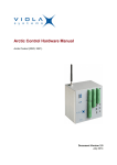
Arctic AMR Hardware Manual
Arctic AMR Hardware Manual (2170)
Firmware Version 1.x
Document Version 1.1
December 2010
Hardware Manual
Arctic AMR Hardware Manual
Copyright and Trademark
Copyright © 2008-2010, Viola Systems Ltd. All rights to this manual are owned
solely by Viola Systems Ltd. (referred elsewhere in this User’s Manual as
Viola Systems). All rights reserved. No part of this manual may be transmitted
or reproduced in any form or by any means without a prior written permission
from Viola Systems.
Ethernet™ is a trademark of XEROX Corporation. Windows™ and Internet
Explorer™ are trademarks of Microsoft Corporation. Netscape™ is a
trademark of Netscape Communications Corporation. All other product names
mentioned in this manual are the property of their respective owners, whose
rights regarding the trademarks are acknowledged.
Viola Systems Ltd.
Lemminkäisenkatu 14-18 A
FI-20520 Turku
Finland
E-mail: [email protected]
Technical Support
Phone: +358 20 1226 226
Fax: +358 20 1226 220
E-mail: [email protected]
Internet: http://www.violasystems.com
Firmware Version 1.x
2
Document Version 1.1
Hardware Manual
Arctic AMR Hardware Manual
Disclaimer
Viola Systems reserves the right to change the technical specifications
or functions of its products or to discontinue the manufacture of any of its
products or to discontinue the support of any of its products without any
written announcement and urges its customers to ensure that the information
at their disposal is valid.
Viola software and programs are delivered “as is”. The manufacturer does not
grant any kind of warranty including guarantees on suitability and applicability
to a certain application. Under no circumstance is the manufacturer or the
developer of a program responsible for any damage possibly caused by the
use of a program. The names of the programs as well as all copyrights relating
to the programs are the sole property of Viola Systems. Any transfer, licensing
to a third party, leasing, renting, transportation, copying, editing, translating,
modifying into another programming language or reverse engineering for any
intent is forbidden without the written consent of Viola Systems.
Viola Systems has attempted to verify that the information in this manual is
correct with regard to the state of products and software on the publication
date of the manual. We assume no responsibility for possible errors which
may appear in this manual. Information in this manual may change without
prior notice from Viola Systems.
Firmware Version 1.x
3
Document Version 1.1
Hardware Manual
Arctic AMR Hardware Manual
Declaration of Conformity
(according to ISO/IEC Guide 22 and EN 45014)
Manufacturer’s Name: Viola Systems Ltd.
Manufacturer’s Address:
Lemminkäisenkatu 14-18 A
FI-20520 Turku
Finland
declares that this product:
Product Name:
Arctic AMR
conforms to the following standards:
EMC:
EN 55022 Emission Test (Class A)
1. Radiated Emissions (30-1000MHz)
2. Conducted Emissions (0.15-30MHz)
EN 50082-1 Immunity Test
1. IEC 801-3: Radio Frequency Electromagnetic Field
2. IEC 801-2: Electrostatic Discharge
3. IEC 801-4: Fast Transients, AC Power Ports and Signal cables
Supplementary Information:
“The product complies with the requirements of the Low Voltage Directive
73/23/EEC and EMC directive 89/336/EEC.”
Warning!
This is a Class A product. In a domestic environment this product may cause
radio Interference which may make it necessary for the user to take adequate
measures.
Manufacturer’s Contact Information:
Viola Systems Ltd.
Lemminkäisenkatu 14-18 A
FI-20520 Turku
Finland
Phone: +358 20 1226 226
Fax: +358 20 1226 220
Firmware Version 1.x
4
Document Version 1.1
Hardware Manual
Arctic AMR Hardware Manual
Warranty and Safety Instructions
Read these safety instructions carefully before using the products mentioned
in this manual:
Warranty will be void if the product is used in any way in contradiction with the
instructions given in this manual or if the product has been tampered with.
The devices mentioned in this manual are to be used only according to the
instructions described in this manual. Faultless and safe operation of the
devices can be guaranteed only if the transport, storage, operation and
handling of the devices is appropriate. This also applies to the maintenance of
the products.
To prevent damage both the product and any terminal devices must always
be switched OFF before connecting or disconnecting any cables. It should
be ascertained that different devices used have the same ground potential.
Before connecting any power cables the output voltage of the power supply
should be checked.
This product is not fault-tolerant and is not designed, manufactured
or intended for use or resale as on-line control equipment or as part
of such equipment in any hazardous environment requiring fail- safe
performance, such as in the operation of nuclear facilities, aircraft navigation
or communication systems, air traffic control, direct life support machines,
or weapons systems, in which the failure of Viola Systems manufactured
hardware or software could lead directly to death, personal injury, or severe
physical or environmental damage.
Firmware Version 1.x
5
Document Version 1.1
Hardware Manual
Arctic AMR Hardware Manual
Revisions
Date
Document Firmware Description of changes
Version
Version
12/2010
1.1
Firmware Version 1.x
1.x
Cable shield images added.
6
Document Version 1.1
Hardware Manual
Arctic AMR Hardware Manual
Contents
COPYRIGHT AND TRADEMARK ........................................................................................ 2
DISCLAIMER..........................................................................................................................3
DECLARATION OF CONFORMITY...................................................................................... 4
WARRANTY AND SAFETY INSTRUCTIONS.......................................................................5
REVISIONS............................................................................................................................ 6
1. INTRODUCTION............................................................................................................... 8
1.1
Safety Operation................................................................................................................... 8
2. HARDWARE...................................................................................................................... 9
2.1
2.2
2.3
2.4
2.5
Power supply......................................................................................................................... 9
Antenna connector.............................................................................................................. 10
System status LEDs............................................................................................................10
Serial port............................................................................................................................ 10
Device identification and product label .............................................................................. 11
3. INSTALLING THE DEVICE.............................................................................................12
3.1
3.2
3.3
3.4
3.5
Unpacking the device..........................................................................................................12
Installing SIM card...............................................................................................................12
Connecting power cable......................................................................................................15
Mounting the back panel.....................................................................................................17
Mounting the device............................................................................................................ 18
4. SPECIFICATIONS ..........................................................................................................19
5. LIMITED WARRANTY.....................................................................................................20
6. TECHNICAL SUPPORT ................................................................................................ 21
Firmware Version 1.x
7
Document Version 1.1
Hardware Manual
Arctic AMR Hardware Manual
1 Introduction
Arctic AMR is an intelligent GPRS modem device for AMR connectivity. The
device has an integrated 1/3 phase AC power supply and GPRS connectivity.
Intended audience for this manual are engineers and technical staff planning
and commissioning the devices to field operations.
1.1
Safety Operation
Warning!
The device uses lethal voltages. Carefully read through all the instructions
in this manual and follow local safety regulations. Device must not be
operated when back panel is removed. Voltage inside the device is extremely
dangerous and may cause death or severe injury.
Warning!
Do not touch the integrated circuits on the circuit board. Static voltage
discharge may damage the components.
Carefully read through all the instructions in this manual before installing or
operating the device.
Firmware Version 1.x
8
Document Version 1.1
Hardware Manual
Arctic AMR Hardware Manual
2 Hardware
This section describes the physical interfaces on Arctic AMR.
The device has four external interfaces:
1. Power supply
2. Serial port (RS-232)
3. Antenna connector (SMA)
4. System status LEDs
Figure 1. Physical Interface
2.1
Power supply
Arctic AMR operates with external AC power. The power supply can be used
in 1 or 3 phase configuration.
Table 1: Power supply range
Voltage range
Phase - Phase
90-440 VAC
Phase - N
52-254 VAC
Power cable installation is described in the chapter Connecting power cable
2
on page 15. Recommended power cabling is (conductor) 0.5mm to
2
2.5mm .
Firmware Version 1.x
9
Document Version 1.1
Hardware Manual
Arctic AMR Hardware Manual
Note!
External fuses are required for each phase line to protect the device. The fuse
with a rating not greater than 2A is recommended. All the connections to the
power connector (phase and neutral) must be connected via all-pole safety
switch.
2.2
Antenna connector
The device has an SMA (female) connector. The antenna has an SMA male
connector.
2.3
System status LEDs
The device has 5 system status LEDs. When the system is fully operational,
all LEDS should be on.
Table 2: LEDs Status
2.4
No. Legend
LED name
Description (LED ON)
1
POW
POWER
Device has AC power and it's operational
2
RUN
RUN
Device SW is running OK
3
SIG
SIGNAL
GPRS signal level is OK
4
NET
NETWORK
GPRS is registered successfully to network
5
MET
METER
Meter connected to device successfully and serial
port is polling
Serial port
The serial port connector is a 9-pin D-sub (female) connector supporting serial
speeds from 300 to 115200 bps.
Serial port signals and pin connections are listed in table 3:
Table 3: Serial Port Pin Connection
Number
Name
Explanation
1
DCD
Data Carrier Detect
2
RXD
Received Data
3
TXD
Transmitted Data
4
DTR
Data Terminal Ready. Handshake output
5
GND
Signal ground
6
DSR
DSR
7
RTS
Ready To Send. Handshake output
8
CTS
Clear To Send. Handshake input
9
RI
Ring Indicator
Firmware Version 1.x
10
Document Version 1.1
Hardware Manual
Arctic AMR Hardware Manual
2.5
Device identification and product label
The device can be identified on product label. The device has a unique serial
number as shown in the figure 2.
Figure 2. Unique serial number
Firmware Version 1.x
11
Document Version 1.1
Hardware Manual
Arctic AMR Hardware Manual
3 Installing the device
This chapter describes the safe installation of the device.
Warning!
The device uses lethal voltages. Device must not be operated when the back
panel is removed. Voltage inside the device is extremely dangerous and may
cause death or severe injury.
3.1
Unpacking the device
Arctic AMR is delivered in a bulk package containing the device itself,
antenna, cable clamp, cable shield and torx screws for back panel mounting.
If any of the items are missing or are damaged, please contact Viola Systems
Ltd. All packaging materials are recyclable. Viola Systems urges its customers
to follow environmental regulations regarding the disposal of all materials.
3.2
Installing SIM card
For GPRS connectivity, SIM card must be installed to the device. SIM card
installation is done using torx (T10). To open the device, open the screws on
bottom of the device (4 pcs).
Warning!
The device must be powered off and power supply cables removed when
installing SIM card. If the device has already been powered, wait for 5 minutes
after all the LEDs have been disabled before opening the device.
Firmware Version 1.x
12
Document Version 1.1
Hardware Manual
Arctic AMR Hardware Manual
Figure 3. Before SIM Installation
When the device is opened, gently push and slide SIM holder for opening the
cover. Insert the SIM card to the cover of the holder and close the SIM holder
in the reversed order.
Figure 4. SIM holder open for installing the SIM card
Firmware Version 1.x
13
Document Version 1.1
Hardware Manual
Arctic AMR Hardware Manual
Figure 5. SIM card inserted and SIM holder closed
Firmware Version 1.x
14
Document Version 1.1
Hardware Manual
Arctic AMR Hardware Manual
3.3
Connecting power cable
Warning!
If the device has already been powered, wait for 5 minutes after all the LEDs
have been disabled before opening the device.
■
When the device is opened, connect phase and neutral cables to power
connector. Power connector is show in figure 6.
Figure 6. Power connector
■
Insert cable shield on top of SIM card holder (see figure 7 and 8).
■
Insert cable to device via cable gland. Tighten the cable gland.
Note!
Install SIM card and cable shield before connecting power cabling.
Warning!
Device must not be operated without cable shield and cable clamp securely
connected.
Firmware Version 1.x
15
Document Version 1.1
Hardware Manual
Arctic AMR Hardware Manual
Table 4: Power connector
N
Neutral
L1
Phase 1
L2
Phase 2
L3
Phase 3
Figure 7. Cable Tightening
■
Securely tighten cables to the power connector as shown in figure 7.
Figure 8. Cable Gland
Firmware Version 1.x
16
Document Version 1.1
Hardware Manual
Arctic AMR Hardware Manual
Note!
Cable gland must be securely connected to prevent cable damage.
3.4
Mounting the back panel
Insert the device back panel and tighten torx screws on bottom of the device
(4 pcs torx T10).
Figure 9. Mounting the device
A
Firmware Version 1.x
Torx screw, 4 pcs
17
Document Version 1.1
Hardware Manual
Arctic AMR Hardware Manual
B
Cable gland
C
Cable gland plug
D
Power connectors
E
Serial port
F
Cable shield
G
Back panel
Warning!
The device uses lethal voltages. Device must not be operated before back
panel is mounted and securely tightened with torx (figure 8).
3.5
Mounting the device
Arctic AMR device can be mounted by using the mounting holes in the back
panel. With these holes, the device can be mounted on a flat surface, for
example a cabinet. If DIN rail mounting (35 mm) is needed, an optional DIN
rail mounting kit (product code 3003) can be mounted to the side panel.
Figure 10. Optional DIN rail mounting installed
Firmware Version 1.x
18
Document Version 1.1
Hardware Manual
Arctic AMR Hardware Manual
4 Specifications
Table 5: Specifications
Product name
Arctic AMR
Product code
2170
Input voltage (Phase – Phase)
90-440 VAC
Input voltage (Phase – N)
52-254 VAC
Power consumption
<5W
Weight
0.3 kg
GSM/GPRS Frequency band
Quad band, 800, 900, 1800 and 1900 MHz
Firmware Version 1.x
19
Document Version 1.1
Hardware Manual
Arctic AMR Hardware Manual
5 Limited Warranty
Coverage
Viola Systems warrants this hardware product to be free from defects in
materials and workmanship for the warranty period. This non-transferable,
limited warranty is only to you, the first end-user purchaser. The warranty
begins on the date of purchase and lasts for the period specified below:
Arctic AMR : one (1) year
Excluded Products and Problems
This warranty does not apply to: (a) Viola Systems software products; (b)
expendable components such as cables and connectors; or (c) third party
products, hardware or software, supplied with the warranted product. Viola
Systems makes no warranty of any kind on such products which, if included,
are provided "AS IS." Excluded is damage caused by accident, misuse, abuse,
unusually heavy use, or external environmental causes.
Remedies
Your sole and exclusive remedy for a covered defect is repair or replacement
of the defective product, at Viola Systems’ sole option and expense, and
Viola Systems may use new or refurbished parts or products to do so. If Viola
Systems is unable to repair or replace a defective product, your alternate
exclusive remedy shall be a refund of the original purchase price.
The above is Viola Systems’ entire obligation to you under this warranty.
IN NO EVENT SHALL VIOLA SYSTEMS BE LIABLE FOR INDIRECT,
INCIDENTAL, CONSEQUENTIAL OR SPECIAL DAMAGES OR LOSSES,
INCLUDING LOSS OF DATA, USE, OR PROFITS EVEN IF VIOLA SYSTEMS
HAS BEEN ADVISED OF THE POSSIBILITY OF SUCH DAMAGES. In no
event shall Viola Systems’ liability exceed the original purchase price of the
device server. Some states or countries do not allow the exclusion or limitation
of incidental or consequential damages, so the above limitation or exclusion
may not apply to you.
Obtaining Warranty Service
You must notify Viola Systems within the warranty period to receive warranty
service. During the warranty period, Viola Systems will repair or replace, at
its option, any defective products or parts at no additional charge, provided
that the product is returned, shipping prepaid, to Viola Systems. All replaced
parts and products become the property of Viola Systems. Before returning
any product for repair, customers are required to contact the Viola Systems.
Firmware Version 1.x
20
Document Version 1.1
Hardware Manual
Arctic AMR Hardware Manual
6 Technical Support
Contacting Technical Support
Phone: +358 20 1226 226
Fax: +358 20 1226 220
E-mail: [email protected]
Internet: http://www.violasystems.com
Recording Arctic Information
Before contacting our Technical Support staff, please record (if possible) the
following information about your Arctic product:
Product name:
___________________________________________________
Serial no:
_______________________________________________________
Note the status of your Arctic in the space below before contacting technical
support. Include information about error messages, diagnostic test results, and
problems with specific applications.
___________________________________________________________________
___________________________________________________________________
___________________________________________________________________
Firmware Version 1.x
21
Document Version 1.1