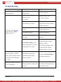
1
JDA 日煬科技有限公司
JD Auspice Co., Ltd.
SPD TESTING INSTRUMENT
Portable Surge Protective Device Tester
SPD T8 tester
User Manual
JD Auspice Co.,Ltd. TEL: 886-2-2595-9780 FAX: 886-2-2595-9412 [email protected] www.jdauspice.com
JDA 日煬科技有限公司
SPD TESTING INSTRUMENT
JD Auspice Co., Ltd.
Index
Cover------------------------------------------------------------- 1
Index-------------------------------------------------------------- 2
Safety Precaution---------------------------------------------- 3
Packaging------------------------------------------------------- 3
Introduction---------------------------------------------------- 4
Standards, applications--------------------------------------- 4
Specification---------------------------------------------------- 5
Control Function---------------------------------------------- 6
Operation Procedure------------------------------------------ 7
Operation Procedure------------------------------------------ 8
Procedure for Batteries Replacement--------------------- 9
Maintenance and Repair------------------------------------- 10
Troubleshooting------------------------------------------------ 11
Measurement Inspection Method-------------------------- 12
Measurement Inspection Method-------------------------- 13
Technical Enquiry--------------------------------------------- 13
-2-
SPD T8 tester
JD Auspice Co.,Ltd.
TEL: 886-2-2595-9780
FAX: 886-2-2595-9412 [email protected] www.jdauspice.com
JDA 日煬科技有限公司
SPD TESTING INSTRUMENT
JD Auspice Co., Ltd.
Safety Precaution
This tester can produce up to 1000V testing voltage. To obtain accurate performance and
prevent injury , please follow the safety instructions below:
1.Before the “TEST” button is pressed, make sure the tester connection with testing
component is complete.
2.During the “TEST” button is pressing, do not touch the testing component and the
cable of the tester.
3.After the “TEST” button is released, wait for about 5 second before touching any
component.
4.Short circuit the testing rods before and after each test.
5.DO not press the “TEST” button when no testing component connected.
6.Make sure the batteries in the tester are in correct polarity
7.Remove the batteries for long-time storage.
8 . When LCD Display shows “LOBAT”, it mean low battery supply, battery
replacement is necessary. Otherwise, accuracy of measurement will be affected and the
internal circuit of the tester may not fully operate.
Packaging
The SPD Tester Box set includes the following items:
Table 1 SPD Tester T8 Item List
ITEM
1
SPD Tester T8
1
2
Tester Bag
1
3
Testing rods
2
4
1.5 V LR6 Alkaline Batteries
4
5
User-manual
1
-3-
SPD T8 tester
JD Auspice Co.,Ltd.
Quantity
TEL: 886-2-2595-9780
FAX: 886-2-2595-9412 [email protected] www.jdauspic
JDA 日煬科技有限公司
SPD TESTING INSTRUMENT
JD Auspice Co., Ltd.
Introduction
Surge Protective Devices Tester, SPD Tester T8 is designed for on-site
testing of Surge Protective Devices (SPD). It allow to measures both the
Nominal Voltage and Leakage Current of different SPDs. Users can
determine the status of these components according to the tester readings.
The tester can measure both type of main component inside SPDs, including:
a)Voltage Limiting Type (MOV, TVS, Zener Diode )
The SPD tester injects a constant current into the component and measure the LetThrough Voltage. Then, the tester can use this voltage to find out the leakage current of
the component.
b)Voltage Switching Type (Gas Discharge Tube, Solid Discharge Tube, Spark Gap)
The SPD tester injects a constant current into the component and measure the Break
Down Voltage of the component. What the tester outputs is slope of 10V/ms voltage not a
constant current
Standards, applications
This Tester is made with reference to IEC 61643 part 1 and part 21
IEC 61643 “Surge protective devices connected to low voltage power distribution
system”
Part 1:
Performance requirements and testing methods. Class I and II tests
IEC 61643 “Surge protective devices connected to telecommunications and signaling
networks”
Part 21: Performance requirements and testing methods
-4-
SPD T8 tester
JD Auspice Co.,Ltd.
TEL: 886-2-2595-9780
FAX: 886-2-2595-9412 [email protected] www.jdauspic
JDA 日煬科技有限公司
SPD TESTING INSTRUMENT
JD Auspice Co., Ltd.
Specification
(i) General
Dimension
(Length x Width x Deep)
Weight
Case Material
Display
252mm ×121mm× 50mm
0.8kg
ABS
LCD 15mm Height Digit
Light Grey Case,Red and Black tester
rod
0℃ ~ 40℃
≤ 75%
-10℃ ~ 50℃
4 × 1.5V LR6 Alkaline Battery
500 measurements
Color
Operation Temp.
Operation Humidity
Storage Temp.
Power Supply
Battery Life
(ii) Technical Specification*
Measurement Range
Range
Resolution
Accuracy
600V
50V~600V
1V
3% + 5
1000V
500V~1000V
1V
3% + 5
600V
50V~700V
1V
3% + 5
1000V
500V~1200V
1V
3% + 5
0~199.9μA
2.0~199.9μA
0.1 μA
5% + 10
1mA DC
Reference
Voltage
Discharge Voltage
Leakage Current
*Internal Buzzer beeps for each successful measurement.
(iii) Safety Parameter
Maximum Overload Current
2mA
Maximum Output Voltage
≤ 1500V
(No Load)
Case Protection Level
IP65
Calibration cycle
Once a year
(recommendation)
-5-
SPD T8 tester
JD Auspice Co.,Ltd.
TEL: 886-2-2595-9780
FAX: 886-2-2595-9412 [email protected] www.jdauspic
JDA 日煬科技有限公司
SPD TESTING INSTRUMENT
JD Auspice Co., Ltd.
Control Function
1. Output Terminal:
RED : Positive
Black : Negative
2. LCD Display
3. Test-Voltage Range Selector “(VS)”
Range:
(i) 600V
(ii) 1000V
4. Voltage Adjustment Switch “(VA)”
5. Operation Mode Selector “(OM)”
Mode:
6.
(i) UN
:
Nominal Voltage Measurement
(ii) VA
:
Test-Voltage Adjustment
(iii)Ileak
:
Leakage Current Measurement
“TEST” button.
-6-
SPD T8 tester
JD Auspice Co.,Ltd.
TEL: 886-2-2595-9780
FAX: 886-2-2595-9412 [email protected] www.jdauspic
JDA 日煬科技有限公司
SPD TESTING INSTRUMENT
JD Auspice Co., Ltd.
Operation Procedure
1. Connection
1.1
Connect the red and black tester rods to the output terminal. Then, short circuit the
tester rods to release the charge inside the tester.
1.2
Open the battery cover and insert four 1.5V LR 6 Alkaline Batteries into the tester.
Make sure the batteries are in correct polarity.
2. Conducting Voltage Measurement
2.1 For the conducting voltage measurement of an unknown SPD (including Voltage
Switching Type and Voltage Limiting Type component):
▲ Turn the Operation Mode Selector, “(OM)” to “(UN)” position.
▲ Press the Test-Voltage Range Selector, “(VS)” switch to “600V”.
▲ Connect the terminal of the component to T8 tester by the two tester rods.
▲ Press the “TEST” button for 2 second until the LCD display a numeric reading
with Unit “V”. A “Beep” sound from the tester buzzer indicates the reading is
valid.
Attention:
▲
1 If the LCD reading exceeds 600V, it means that the Nominal Voltage is
○
larger than 600V. It is required to turn the “(VS)” to the “1000V” side and
repeat the test again.
2 If the LCD reading is inside the range of test voltage of “(VS)”, it means
○
“(VS)” selection is correct and the reading is valid.
3 If no “Beep” sounds after the “TEST” button is pressed, it means the current
○
across the MOV is less than 1mA or the Gas Discharge Tube does not reach
the Break Down Voltage. So the reading is invalid. Please check “(VS)” if it
is set to “1000V” or the output terminal is open-circuit.
Note: The reading is the Nominal Voltage---for Voltage Limiting Type (e.g. MOV). If
it is Voltage Switching Type (e.g. Gas Discharge Tube), the reading is Break Through
Voltage.
-7-
SPD T8 tester
JD Auspice Co.,Ltd.
TEL: 886-2-2595-9780
FAX: 886-2-2595-9412 [email protected] www.jdauspic
JDA 日煬科技有限公司
SPD TESTING INSTRUMENT
JD Auspice Co., Ltd.
2.2 For the measurement of known SPD Nominal Voltage
★ Switch “(OM)” to “(UN)” position.
★ According to component Nominal Voltage, if it is less than 600V, then press the
“(VS)” to “600V” position; if it is larger than 600V then press the “(VS)” to
“1000V” position.
★ Connect the tester to the testing component by the tester rods.
Press the “TEST” button, until the buzzer produces “Beep” sound, LCD shows
the stable value with the unit “V”, then release the “TEST” button.
Compare the reading with the specification of the component.
★ Attention:For Nominal Voltage measurement, the reading is valid only after the
“TEST” button is pressed for more than 2 second with the “BEEP” sound as
indication from the tester buzzer. Otherwise, the reading is invalid.
2.3 Leakage Current Measurement
◆ Connect the testing component to the tester by the two testing rods.
◆ Turn “(OM)” to “(VA)” Position.
◆ According to the preset testing voltage, turn the adjust “(VS)” to a suitable
position:If the testing voltage is smaller than 600V, turn “(VS)” to “600V”
position. For more than 600V, turn “(VS)” to “1000V” position.
◆ Press the “TEST” button, adjust the “(VA)” button (Clockwise: Increase,
◆ Aclockwise: decrease) until the display value equal to the preset value, then release
the button.
◆ Switch “(OM)” to “ILeak” position and press the
“TEST” button, The LCD display the leakage
current(μA)of the testing component.
1 The maximum reading for leakage current is 199.9μA. For reading
Attention:○
larger than 199.9μA will only display a “1” on tester LCD.
2 “There are no beep sound indication on operation mode “(OM)” on
○
“(VA)” and “ILeak” position.
-8-
SPD T8 tester
JD Auspice Co.,Ltd.
TEL: 886-2-2595-9780
FAX: 886-2-2595-9412 [email protected] www.jdauspic
JDA 日煬科技有限公司
SPD TESTING INSTRUMENT
JD Auspice Co., Ltd.
Procedure for Battery Placement
The tester uses four 1.5V LR 6 ALKALINE batteries as power supply. When the LCD
shown the “LOBAT” , it is necessary to replace the batteries..
Here is the procedure:
1. Remove the tester rods;
2. Screw up the screws at the back of the tester;
3. Open the battery cover;
4. Remove the old batteries;
5. Install the new batteries; screw the battery cover back to the tester.
-9-
SPD T8 tester
JD Auspice Co.,Ltd.
TEL: 886-2-2595-9780
FAX: 886-2-2595-9412 [email protected] www.jdauspic
JDA 日煬科技有限公司
SPD TESTING INSTRUMENT
JD Auspice Co., Ltd.
Maintenance and Repair
To make sure each measurement is accurate, keep the tester away from : shock、
corrosive gases, salt and high temperature, etc.
★ After testing, remove the tester rods and bring all things back to the tester box.
For long time not using the tester, please remove the batteries.
★ If the LCD display “LOBAT” after pressing the “TEST” button, it mean low
battery supply, please replace the battery.
If the tester requires maintenance, please contact the supplier, they will bring the tester
back to the technical service centre for further inspection.
- 10 -
SPD T8 tester
JD Auspice Co.,Ltd.
TEL: 886-2-2595-9780
FAX: 886-2-2595-9412 [email protected] www.jdauspic
JDA 日煬科技有限公司
SPD TESTING INSTRUMENT
JD Auspice Co., Ltd.
Troubleshooting
Problem
Cause
NO LCD display after “TEST”
No batteries or batteries in
button is pressed
wrong polarity
Voltage Range “(VS)”
setting is too low.
(i.e. “600V”)
Suggestion
Check the batteries
Turn the switch, “(VS)”
to“1000V” Position
Check if the Tester Rod are
Tester Rods Open Circuit
connected to the tester and the
testing component
Testing Component is Open
No “Beep” sound from the
Buzzer after the “TEST”
button is pressed.
Circuit
Check the component or
replace another one
Low Batteries power
Replace the batteries
Position of the “(OM)” is not
Turn “(OM)” to the (UN)”
on “(UN)”
Position
-For Voltage limiting
The Nominal Voltage of the
testing component exceeds the
testing range of the tester
Component, Max. Testing
Voltage is 1000V
-For Voltage Switching Type
Component, Max. Break
through voltage is 1200V
After “(OM)” Turn to “(VA)”
Position and press “TEST”
The testing component is
button, Output voltage remains
conducted but the output
constant no matter adjusting
voltage is limited.
Check the Nominal Voltage of
the testing component
the “(VA)”.
During the leakage current test,
the LCD displays “ 1 ”
The leakage current of the
testing component is larger than the voltage for leakage current
199.9μA
measurement again
- 11 -
SPD T8 tester
JD Auspice Co.,Ltd.
Turn “(OM)” to “(VA)” and set
TEL: 886-2-2595-9780
FAX: 886-2-2595-9412 [email protected] www.jdauspic
JDA 日煬科技有限公司
SPD TESTING INSTRUMENT
JD Auspice Co., Ltd.
Measurement Inspection Method
The following method suitable for the tester after periodic check or maintenance
1. Check for Output Voltage Accuracy
(1)
Turn “(OM)” to “(VA)” position, connect the output terminal to a standard
voltmeter.
(Red Terminal: positive pole; Black Terminal: Negative Pole)
(2)
Press the “TEST” button and adjust the “(VA)” button, compare the LCD
reading with the reading on the voltmeter. Check if the different in reading is
inside an acceptable range of error percentage.
2. Check for the error of Constant Current
(1)
Turn “(OM)” to “(UN)” position, connect the output terminal with a standard
resistor (error ± 0.5%).
(2)
Press the “TEST” button, read the reading on the LCD until “BEEP” sound
from the buzzer. Obtain the current value (Reading Voltage/Standard Resistance)
if it is equal to the constant current value(1mA) from the tester, error should be
smaller than ± 5%.
3. Check for the measurement error of the Leakage Current
(1)
Connect with standard resistor 10MΩ ± 0.5% to the output terminal.
(2)
Turn “(OM)” to “(VA)” position. Press the “TEST” button. Adjust the “(VA)”
knob to a suitable voltage display.
(3)
Keep pressing the “TEST” button and turn
“(OM)” to “ILeak” position
simultaneously.
(4)
Obtain the leakage current value (Voltage on voltmeter/Standard Resistance).
(5)
The different between the LCD reading and the value obtained on previous step
should be smaller than ± 3% + 10 digit.
4. Check for Conducting Voltage Measurement Accuracy
(1)
Turn the Operation Mode Selector, “(OM)” to “(UN)” position.
- 12 -
SPD T8 tester
JD Auspice Co.,Ltd.
TEL: 886-2-2595-9780
FAX: 886-2-2595-9412 [email protected] www.jdauspic
JDA 日煬科技有限公司
SPD TESTING INSTRUMENT
JD Auspice Co., Ltd.
(2)
Set the Test-Voltage Range Selector, “(VS)” to “600V”.
(3)
Screw up the screws at the back of the tester. Oper the battery cover.
(4)
Connect the output terminal with a gas tube. Simultaneously, connect the red
terminal with the signal lead of oscilloscope probe, connect the negative pole of
the battery with the reference lead of oscilloscope probe. Press the “TEST”
button, read the reading on the LCD until “BEEP” sound from the buzzer.
Obtain the breakdown voltage to check if the different in reading and the
oscilloscope measurement is inside an acceptable range of error percentage.
(5)
Set the Test-Voltage Range Selector, “(VS)” to “1000V” and repeat the above
steps.
- 13 -
SPD T8 tester
JD Auspice Co.,Ltd.
TEL: 886-2-2595-9780
FAX: 886-2-2595-9412 [email protected] www.jdauspic