1
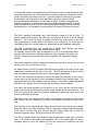
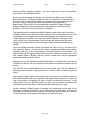
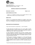
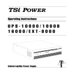
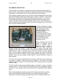
VRe Service Manual
Rev.1
November 12, 2001
VRe GENERAL DESCRIPTION
The VRe power line conditioner is designed to provide exceptionally high availability of
power and offer comprehensive protection from large power line (utility) fluctuations and
disturbances, to critical loads such as Telecom Rectifiers and UPS systems.
VRe provides a regulated output that is well within the input requirements of such critical
loads, while accepting a wide input voltage range of 160VAC to 330VAC. The VRe also
protects such critical loads from lightning surges and power transients. The VRe has
Over-Voltage Protection that protects loads from being subjected to excessive input
voltage. The VRe provides increased availability of power to the critical loads with its
built-in Failsafe Automatic Bypass that allows the load to be powered even in the unlikely
event of internal component failure.
The VRe is capable of providing
regulated output while operating
over a wide input range of
160VAC to 330VAC. Unlike
most existing power
conditioners, the VRe is
specifically designed to handle
this wide range of input voltage
at full rated power over the
entire specified operating
temperature range.
Upon energization, the VRe will
provide a regulated nominal
output of 220VAC with a
regulation range of +7%/-10%,
when the input voltage is
between 180VAC and 300VAC. If the input voltage is beyond this range during
energization, the output is safely disabled. Once the input voltage is within the abovespecified range, output is activated, and the VRe will continue to provide regulated
output. After the output is activated, theVRe will also support the loads over the wider
input range of 160VAC to 330VAC, with the output confined to the range of 192VAC to
264VAC. When the input voltage is below 160VAC or above 330VAC, the output is
safely disabled.
The VRe is able to provide regulated output over such a wide range of input through its
five stages of regulation. Within each stage of regulation, it is normal for the output
voltage to vary in proportion to the input voltage, while remaining within the specified
regulation range.
The VRe switches between the regulating stages as required, in order to provide a
regulated output. In many instances, such switching may result in perceptible change in
the value of output voltage, while still remaining within the specified output regulation
range.
While switching between regulation ranges, the VRe temporarily resorts to providing
power to the load directly from the input power line, through a temporary bypass
mechanism. This lasts for typically two power cycles only. The transfer into and out of
Page 1 of 9
VRe Service Manual
Rev.1
November 12, 2001
this temporary bypass is accompanied by a brief break of power to load lasting less than
one-quarter of power cycle. The transfer to the temporary bypass in indicated by a brief
flicker of the Red LED visible to the user. To prevent nuisance switching due to power
line transients, the VRe dwells in each regulation stage for a minimum of 200
milliseconds before switching to the next required stage. The VRe is designed with
sufficient "hysteresis" to prevent back-and-forth switching between stages, even with
higher impedance sources such as fossil-fuel generators. When the unit is providing
regulated output, it is indicated by a continuously ON Green LED visible to the user.
The VRe is capable of operating over a wide frequency range of 47 Hz to 63 Hz. To
provide optimum performance, the VRe can be configured for 50 Hz or 60 Hz nominal
operation. This is done by a pair of jumpers located in the control circuit of the VRe.
This programming is normally done in the factory, prior to shipping. For instructions on
reconfiguring the unit's nominal frequency, please refer to the Installation Instructions.
The VRe is specially fitted with components to handle large lightning and power
transients, with no significant impact on the output voltage.
For example, when the VRe input is subjected to a 6 kV / 3 kA Combination Wave
simulating the most severe of lightning surges for such equipment, the output "letthrough" voltage will be less than 200 volts in amplitude, with insignificant energy
content.
The parallel capacitors and the large series inductance combine to reduce the rise-time
(dv/dt), from 6 kv/µs to less than 20 V/µs.
An added feature is an LED indicator that monitors the health of the most critical surge
suppression component at the input of the VRe. The LED will light up in case of failure
of this component, thus alerting the user for the necessary replacement.
The VRe has many built-in features to protect the load from exposure to any level of
voltage that may be beyond the load's acceptable operating input voltage range. The
most prominent is the Over-Voltage Protection feature. If the output voltage approaches
264VAC for any reason, the OVP ensures that the output is safely disabled.
The output will remain disabled for a minimum of one cycle, and the unit will resume
power to the load only after ensuring that the output voltage will be below 240VAC. The
OVP thus protects the loads from possible catastrophic failure that could result from
harmful sustained over-voltage.
When the unit is in the protective OVP state, it is indicated by a continuously ON Yellow
LED visible to the user, alerting the user about the temporary disruption of power to the
load.
The VRe also has a complementary feature to protect the load from low input voltage.
When the output of the VRe falls below 192VAC, the output is safely disabled and power
to the load is resumed only after ensuring that the output voltage will be within the
specified regulation range. During this state, all LEDs are OFF.
The VRe is equipped with a circuit-breaker rated to handle the full load even at 160VAC
input. In the event of the output load exceeding 125% of the rated system VA over a
sustained period of time, the breaker will trip and prevent the excessive load from
Page 2 of 9
VRe Service Manual
causing possible dangerous hazards.
please refer to Product Specifications.
Rev.1
November 12, 2001
For more information on the circuit-breaker,
Unlike most existing power conditioners, the VRe has the added feature of Failsafe
Automatic Bypass. This feature enables the VRe to provide power to the load even in
the unlikely event of internal failure that may otherwise result in disruption of power to
the load. If output voltage of the VRe were to be below acceptable limit for
approximately 100 ms, the VRe will automatically activate the Failsafe Automatic
Bypass, enabling the load to be powered from the power line, while still offering
protection to the load from harmful power line transients.
This feature provides increased Availability of power to loads, which may be critical to
installations with Telecom Rectifiers or UPS systems. Even in this Bypass state, the VRe
has additional Over-Voltage Protection that safely disables the output as the output
voltage approaches 264VAC. The output will remain disabled for a minimum of one
cycle, and the unit will resume power to the load only after ensuring that the output
voltage will be below 240VAC, thus protecting the load from harmful sustained overvoltage.
Once the Failsafe Automatic Bypass is activated, the VRe will stay in this state till the
user resets the system. This can be done either by pressing the Bypass Reset button
available to the user, or by recycling power to the VRe through the circuit-breaker. It is
recommended that the Bypass Reset button be used to attempt the system reset. If the
VRe transfers again to Bypass, this may confirm internal failure and the appropriate
service procedure should be initiated.
When the unit is in the Failsafe Automatic Bypass state, it is indicated by a continuously
ON Red LED visible to the user, alerting the user about the possible immediate need for
service.
The VRe has many failsafe features built into the control logic, with the objective of
providing continued power to the load even in the unlikely event of internal component
failure.
One important failsafe feature is the elimination of simultaneous conduction of the two
Solid State switches used in the regulation and bypass paths respectively. Hence, as
long as one switch is conducting, the other is forcibly blocked from conduction. In the
unlikely event of any one SSR failing short, the other is prevented from conducting, thus
preventing further internal failure, and ensuring continued power to the load.
Another noteworthy failsafe feature is separate and independent control logic for the
regulating and bypass subsystems. In the unlikely event of a logic failure, such fault will
be isolated and confined to that subsystem, permitting the other subsystem to continue
function flawlessly without permanent disruption of power to the load.
Page 3 of 9
VRe Service Manual
Rev.1
November 12, 2001
VRe SYSTEM BLOCK DIAGRAM
AC Input
AC Output
PZ00063 Filter Circuit
Board Assembly
Input/Output Board
WZ00115
12-Circuit Connector
Assembly
PZ00062A
LED
Board
Assembly
PZ00062-A Board and Heatsink Assembly
VRe Main Circuit Board
TP00125 or TP00126
VRe Transformer
With 8-Pin Connector
Page 4 of 9
VRe Service Manual
Rev.1
November 12, 2001
REPAIRING VRe IN THE FIELD
VRe is designed to facilitate quick replacement of modules in the field. Therefore, trouble
shooting procedures described in this manual are limited to identification of faulty
modules that can be replaced by persons with a general knowledge of electronics.
Actual board level trouble shooting and calibration requires a full training course at TSi.
Thus the great majority of customers will find it more cost effective to replace modules.
The above Block Diagram shows these major modules, as well as a picture of each
module.
Spare parts can be ordered from TSi directly and the below Spare Parts Table provides
correct part numbers. Please contact TSi prior to ordering parts to ensure that you will
receive the correct ones for you particular version of VRe.
Note 1: For customers with a large number of VRe units:
Since board exchange is the quickest way to repair a failed VRe unit, TSi Power
recommends that customers keep at least 3% (one board set for every 30 VRe units)
in spare main boards in order to minimize VRe downtimes while failed spare boards are
being repaired at TSi Power.
Note 2: For international customers with a large number of VRe units:
Keeping about 5% (one board set for every 20 VRe units) in spare boards is highly
recommended to minimize VRe repair time. Also, shipping costs (per each repaired
board) can be reduced dramatically by always shipping a group of 3 or more boards in
the same box, as the cost of international air shipment can be very high.
HOW TO RETURN DEFECTIVE MODULES FOR REPAIR OR REPLACEMENT
1. Contact TSi via telephone, fax or e-mail to obtain a Return Material Authorization
number (RMA).
2. Make sure that returned parts are properly protected and packed in suitable
shipping box, especially when sending parts via United Parcel Service.
3. Mark shipping box with RMA number, using indelible marker pen.
4. We recommend that DHL is used for shipments originating outside the USA and
FedEx for US domestic shipments. Do not use UPS if possible.
5. Upon receiving the part TSi will determine if it is covered by warranty—warranty
repair or replacement is performed without charge. TSi will quote repair costs for
out-of-warranty parts prior to starting any repair work. If repair is not cost
effective TSi will quote the cost of a replacement part.
6. Shipping costs, duty and brokerage costs are the responsibility of the customer.
TSi Power Corporation
1103 West Pierce Avenue
Antigo, WI 54409, USA
Telephone:
Facsimili:
e-mail:
URL:
+1-715-623-0636
+1-715-623-2426
[email protected]
www.tsipower.com
RECOMMENDED SPARE PARTS
Page 5 of 9
VRe Service Manual
Part Number
PZ00062
Rev.1
TP00125
Description
Board and heatsink
assembly for VRe3000/5000-230
Board and heatsink
assembly for newer
VRe-3000/50000229/0230/0231
LED display board
assembly
Filter circuit board
assembly
12-Circuit connector
assembly
3-kVA transformer
TP00126
5-kVA transformer
FC00027
20-A single-pole
circuit breaker
32-A single-pole
circuit breaker
20-A single-pole
circuit breaker
20-A double-pole
circuit breaker
PZ00062-1
PZ00062A
PZ00063
WZ00115
FC00028
FC00017
FC00044
FC00045
35-A double-pole
circuit breaker
JP00076
Mains wiring
terminal for DIN-rail
mounting
Earth wiring
terminal for DIN-rail
mounting
JP00077
November 12, 2001
Comments
Used in original compact version
of VRe and is not compatible with
newer version.
Used in newer version of VRe and
is not compatible with older
versions.
Compatible with all versions of
VRe
Compatible with all versions of
VRe
Used to connect filter and main
boards in all versions of VRe.
Main buck-boost transformer for
all 3-kVA units.
Main buck-boost transformer for
all 5-kVA units.
ABB S271K20, used with older 3kVA VRe units
ABB S271K25, used with older 5kVA VRe units
Carling Switch rocker-type, used
with newer 3-kVA VRe units
Used with dual-phase and nonearthed mains. Newer 3-kVA units
only
Used with dual-phase and nonearthed mains. Newer 5-kVA units
only
Phoenix Contact, UK10N, used
on all VRe versions.
Phoenix Contact, USLKG10N,
used on all VRe versions.
Page 6 of 9
VRe Service Manual
Rev.1
November 12, 2001
VRE-3000/5000 STEP-BY-STEP TROUBLE-SHOOTING PROCEDURE
Step 1: Visual Status Indicators
1. The only indicator that must be illuminated is the green “regulation” LED.
2. If the green “regulation” LED is not illuminated, it could mean following:
a) there is no AC power outage or it is below 180 volts,
b) circuit breaker in the rear of VRe is in OFF position,
c) internal fuse(s) inside VRe are blown, or
d) internal overcurrent protection device(s) have activated.
3. If the yellow “Over Voltage Protection” or “OVP” LED is illuminated, then
it means that the AC mains voltage is too high (above 310 volts).
When the voltage drops below 300 volts, then the “OVP” LED will turn off
and the VRe will resume normal operation.
4. If the red “Bypass” LED is constantly illuminated, it means that there is
a failed component or circuit which prevents VRe from normal operation.
Press the “Bypass Reset” switch (using the tip of ballpoint pen or pencil)
- the “Bypass” LED will turn off if it was just a temporary fault.
5. If the red “Replace MOV” LED is illuminated, it indicates a damaged MOV
caused by a severe surge/spike event or over-voltage of over 380 volts.
6. If normal operation of VRe (only the green “regulation” LED is illuminated and the
unit is producing regulated output voltage within 192 to 264 volts) does not
resume even after correcting one of the above potential error conditions(such as
AC power restoration, circuit breaker in OFF position or by pressing the “Bypass
Reset” switch), then defect is inside the VRe.
7. VRe-3000/5000 de-commissioning steps are:
a.
turn off the connected load equipment,
b.
unplug/disconnect from VRe’s output socket or terminal block,
c.
turn off the circuit breaker in the rear of VRe,
unplug/disconnect the VRe from input 230VAC mains source.
8. Move to a well-lit repair bench with tools needed to perform internal parts
inspection and possible electrical tests, troubleshooting, and internal parts
repair/replacement work.
Page 7 of 9
VRe Service Manual
Rev.1
November 12, 2001
Step 2: Internal Parts Visual Inspection
1. Place a failed VRe-3000/5000 on a workbench under a bright light.
2. Remove the cover of the VRe by loosening the bolts from the sides & rear.
3. Make sure that all the wires & cable assemblies are in place and there is no
loose wire or cable assembly without terminating on a board or part.
4. Look for any “burn marks” on the boards – especially under and around
the MOV (metal oxide varistors) which can burn when activated by surge, spike
or over-voltage.
5. Look for any other burned, damaged, cracked or discolored parts which might
provide a clue as to what might have caused the VRe failure.
6. If no defect is found even after visual inspection, you may decide to ship the
entire VRe unit back to TSi Power for factory repair. Typical repair turnaround
time (including transit time) is about 2 to 3 weeks.
Step 3: Main Board Removal Procedure
1. If you are a technician or engineer who is qualified to perform soldering work, then
you may wish to perform following board-level repair.
2. Remove the PZ00062 main board assembly (the largest board) by loosening the
bolts holding the 4 corners of the board to the case base. Also remove the 2 or 3
bolts between the heatsink and case base.
3. Remove the ribbon cable connector from J4 (connector with 14 pins) after
observing and making a sketch of the direction (orientation) of the ribbon cable.
4. Remove the 12-wire connector assembly (from AC input/output board assembly PZ00063) by pressing on the 2 locking latches on the sides of the connector’s
plastic housing and pulling gently.
5. Remove the 8-wire connector assembly (from the large buck/boost transformer)
the same way.
Page 8 of 9
VRe Service Manual
Rev.1
November 12, 2001
Step 4: Fuse Test/Replacement & Board Replacement Procedure
1. Check the fuses (or current limiting devices) on the board – F1, F2, F3, F4 and
F5 (5 locations) using a DMM or continuity tester. If any fuse shows open (or
more than 10 ohm), then it must be replaced by the fuse of same rated voltage,
current and operating speed. Please call factory for advice.
2. If the VRe is not operating normally even with all good fuses, then the PZ00062
main board can be sent back to TSi Power for board repair.
3. When a new spare (or repaired) board is received, please verify that the
frequency selection jumper on the J5 (3-pin) connector is set correctly. For 60Hz
countries (USA and some Asian and South/Central American countries), the
jumper should be across the top 2 pins while for 50Hz countries (Europe, most of
Africa and some countries in Asia & South America), the jumper should be
across the two bottom pins.
4. Perform Step 3 in reverse order to put the PZ00062 board back in the VRe. Plug
in a 100 watt light bulb to VRe’s output socket, connect the input power cord to
230VAC, then verify that VRe is working correctly. If you also have a VARIAC
(variable AC supply), then you can change the input voltage from 150 to 335
VAC and verify all the functions described in the VRe General Description
section above.
Page 9 of 9