1
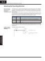
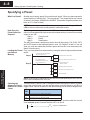
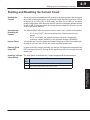
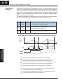
Setting Up and Controlling the Counting " DirectSOFT " " " ! " ! " " " 14 4–2 Setting Up and Controlling the Counting Introduction to Using DirectSOFT You may recall an earlier example that showed you how to use the CPU RLL program to move the HSC parameters in and out of shared memory. The easiest way to create the RLL program is by using our Windows-based software, DirectSOFT. We won’t try to show you all of the DirectSOFT features here, but it may be helpful for you to understand a few simple concepts. You should refer to your DirectSOFT User Manual for a complete overview of the software features. Once you enter the Edit mode, you will have several ways to enter your program elements. Below is a screen showing a portion of the program that has been entered while in the Edit mode. We are using the Ladder View. Setting Up and Controlling the Counting You can use a Watch Window by “clicking” on the Watch Window icon or by using the Debug-New Watch menu option. You can also use the hot key, CTRL+SHIFT+F3, to select the same option. You can open several Watch Windows if you like. Refer to your DirectSOFT documentation for details. One example usage for the Watch Window feature (when working with the HSC) is to monitor the V-memory area where you might be exchanging information back and forth with the HSC’s shared memory. 4–3 Setting Up and Controlling the Counting Selecting the Counting Mode Determining Which Mode to Use You need to decide which mode of counting to use. If you are using a quadrature signal input device, then obviously you will need to use the quadrature mode. If you are using a single-channel encoder, you will want to use the standard UP/DOWN mode. The following page shows you the RLL for selecting the counting mode. Quadrature Counting Quadrature Encoder INA INB Leading and lagging signals INZ Pulses once per revolution Quadrature encoders require that you connect to both the INA and INB terminals. They can sense direction and are inherently more immune to noise than single encoders. Quadrature encoders have a Z-marker that will aid in home search applications when connected to INZ by determining a zero or reference point in the angular displacement of the encoder’s shaft. The single channel encoders (used for standard UP/DOWN counting) do not have Z–markers. When the HSC is not engaged in home search, you can use the Z-marker signal at INZ to reset the counter. We will show you how to do that in a moment on Page 4-10. With standard counting you can use the two counting input signals (INA and INB)of the D4-HSC. One input is used for counting UP and the other used for counting DOWN. You can’t use both inputs for the same direction of counting. UP/DOWN Counting Using Two Inputs One Channel Encoders INA INB You could be using only one of the inputs if desired. In this case, the other input terminal should be left unwired. You control the direction of counting by the manner in which you set a certain bit in your control program (shown later). UP/DOWN Counting Using One Input INA INB Unused Ladder Logic for You will recall from the I/O configuration Determining the table that the HSC uses Ym+13 to control Counting Mode the counting mode. If you have your HSC in slot 0, this means Y13 is the data point you use in your ladder logic. By default, the mode is set to count as if the signals at INA and INB are from a quadrature encoder (Ym+13 OFF). If you want standard, non-quadrature UP/DOWN counting you have to set Ym+13 to ON. Below is a sample rung of logic that selects the UP/DOWN mode. For simplicity, we have assumed the HSC is in slot 0. When SP0 is turned ON (first scan only), the HSC will be configured to count in the UP/DOWN mode. Select the UP/DWN counting mode First scan only SP0 UP/DWN mode Y13 SET Setting Up and Controlling the Counting One Channel Encoder 4–4 Setting Up and Controlling the Counting Selecting the Counting Direction How Ym+13 and Ym+14 Together Determine Counting Direction The status of Ym+14 determines the direction of the counting, that is, UP or DOWN. If you are in the quadrature mode, the HSC will determine whether it is to count UP or DOWN by looking at the status of Ym+14 and seeing which of the signals (INA or INB) is leading. The HSC will determine direction of counting by looking at the status of Ym+14, the counting mode Ym+13, and (if a quadrature signal), whether INA or INB is leading or lagging. The table below summarizes how this information is used. Mode Status Criteria Used For Determining Direction Direction Ym+13=0 Ym+14=0 Counts UP if INA leads INB. Counts DOWN if INB leads INA (quadrature) Ym+13=0 Ym+14=1 Counts UP if INB lead INA. Counts DOWN if INA leads INB (quadrature) Ym+13=1 Ym+14=0 Counts UP with INA. Counts DOWN with INB (standard UP/DOWN) Ym+13=1 Ym+14=1 Counts DOWN with INA. Counts UP with INB (standard UP/DOWN) Using this criteria, the following sample ladder logic would cause the HSC to count in the UP/DOWN mode. The count from INA would be DOWN and the count from INB would be UP. Ladder Logic to Select Counting Direction Assuming that the HSC is in Slot 0: First scan only SP0 UP/DWN mode Y13 SET Setting Up and Controlling the Counting Direction of Counting Y14 SET Select the UP/DWN counting mode Counts DOWN with INA. Counts UP with INB. Ym+13=1 Ym+14=1 Setting Up and Controlling the Counting 4–5 Selecting the Counting Resolution In the UP/DOWN mode, the resolution is fixed at 1x. However, in the quadrature mode, you can control which signal (INA or INB) and what edges of the signal cause a count change. This allows you to effectively double or quadruple the resolution. You have three choices: Choose From 3 Resolution Settings S 1x: One edge of INA causes count change S 2x: Both edges of INA cause count change S 4x: All edges of INA and INB cause count change Ym+14 controls the direction of the counting, but Ym+16 and Ym+17 in combination control which signal and how many edges will cause the count to change. Ym+16 Ym+17 OFF OFF 1x: One edge of INA ON OFF 2x: Both edges of INA OFF ON 4x: All edges of INA and INB ON What Causes Count Change ON 4x: All edges of INA and INB Y No. Function Ym+14 Change state to change count direction Ym+15 ON will invoke home search ON for x2 count operation (quadrature mode only/Ym+17 must be OFF) ON for x4 count operation (quadrature mode only) Ym+16 Ym+17 Quadrature 1x Operation (One Edge: INA trigger) INA is leading INB;so it counts UP INB is leading INA;so it counts DOWN (See note below.) INA INB 1 -1 2 -2 3 -3 4 -4 3 -3 2 -2 1 -1 Note: In this resolution mode, the reason the trailing edge causes a count change (when INB leads INA) is the change will occur when INB is low only. Quadrature 2x Operation (Two Edge: INA trigger) INA is leading INB;so it counts UP INB is leading INA;so it counts DOWN INA INB TIME Ym+14=OFF Ym+14=ON 1 -1 2 -2 3 -3 4 -4 5 -5 6 -6 7 -7 8 -8 7 -7 6 -6 5 -5 4 -4 3 -3 2 -2 1 -1 Quadrature 4x Operation (All Edges: INA and INB trigger) INA is leading INB;so it counts UP INB is leading INA;so it counts DOWN INA INB TIME Ym+14=OFF Ym+14=ON 1 -1 2 3 4 5 6 7 8 9 10 11 12 13 14 15 -2 -3 -4 -5 -6 -7 -8 -9 -10 -11 -12 -13 -14 -15 14 13 12 11 10 9 8 7 6 5 4 3 2 1 -14 -13-12 -11 -10 -9 -8 -7 -6 -5 -4 -3 -2 -1 Setting Up and Controlling the Counting TIME Ym+14=OFF Ym+14=ON 4–6 Setting Up and Controlling the Counting Why Change the Counting Resolution? Example RLL: 2x Resolution The answer to “Why change the counting resolution”? is simply a matter of how much control you need for precise positioning. You may want to increase the resolution so that you receive a higher number of counts per encoder shaft revolution. This gives you more control. Assuming that the HSC is in Slot 0, the following logic would select 2x resolution: First scan only SP0 quad mode Y13 RST Select the quadrature counting mode Y16 SET Select 2x counting resolution Doubles the resolution Y17 RST Example RLL: 4x Resolution Assuming that the HSC is in Slot 0, the following logic would select 4x resolution: First scan only SP0 quad mode Y13 RST Select the quadrature counting mode Y16 SET Select 4x counting resolution Quadruples the resolutiton Y17 SET Setting Up and Controlling the Counting Default Setting By default, Ym+16=0 and Ym+17=0. This means that you are in the 1x resolution mode for quadrature counting until you change the resolution in your ladder logic. Setting Up and Controlling the Counting 4–7 Specifying an Offset What is an Offset? This is an optional feature, but sometimes you may want to start your counting with some number other than zero. This is a perfect example of using an offset. You can also change the current count “on the fly” by using an offset. Either way, it is a three step process: Step1 – Load the offset value (Range=–8388608 to 8388607) into V-memory Step2 – Transfer the value out of V-memory by writing it to shared memory. Step3 – Write the offset value to the current count by either of two ways: S Send a signal from a field device attached to the external LD input of the module. Ym+22 must be ON to enable this feature. This is the external method. S Use your ladder logic to turn ON Ym+2. This is the internal method. External Method For simplification purposes, let’s look at an example where you have your HSC in Slot 0 of your base. The rung of logic shown below will prepare the HSC to use an offset value. Then, if you have a field device hooked to the LD terminal connections, and you turn the device ON, the HSC will will copy the value stored in the shared memory address 04 to 07 (offset) to the current count. In contrast, if Ym+22 was OFF, the HSC would not respond to any signal at the LD connection. In the example below, C0 will determine if the offset gets written to current count. Load offset value of 3500 (BCD) into V2003/V2004 Step 1 SP0 ON first scan only LDD K3500 Copy offset value from V2003/V2004 to shared memory SP0 OUTD V2003 LD K0 Step 2 LD K4 LD K04 WT V2003 C0 Internal Method Step 3 Y22 OUT CPU memory area Location of HSC in base: Base 0 and slot 0 Transferring 4 bytes (offset value) into shared memory starting at hex 04 from V2003/V2004 Enable LD input terminals If you are using the internal method, everything would remain the same except the final rung of logic (Step 3). Here you would use C0 to turn ON Y2. Load offset value of 3500 (BCD) into V2003/V2004 Step 1 SP0 ON first scan only LDD K3500 Copy offset value from V2003/V2004 to shared memory SP0 OUTD V2003 LD K0 Step 2 LD Note: We used SP0 in the above steps, but you could use any permissive contact instead. K4 LD K04 WT V2003 C0 Step 3 Y2 OUT Load value into accumulator Range= –8388608 to 8388607 CPU memory area Location of HSC in base: Base 0 and slot 0 Transferring 4 bytes (offset value) into shared memory starting at hex 04 from V2003/V2004 Transition Y2 from OFF to ON Setting Up and Controlling the Counting Note: We used SP0 in the above steps, but you could use any permissive contact instead. Load value into accumulator Range= –8388608 to 8388607 4–8 Setting Up and Controlling the Counting Specifying a Preset What is a Preset? Another way of saying “preset” is to use the word “target”. When you place a preset in shared memory, it tells the HSC, “This is my target!”. Your target can be any number of pulses in the range –8388608 thru 8388607. (Remember, negative presets must have an “8” in front of them.) NOTE: If you do not use a preset (i.e. you have no target count), always set Ym+20 = ON to ensure continuous counting without inadvertent resets. How Does the Preset Affect the Outputs? Each time your ladder logic instructs the HSC to enable your HSC outputs, the HSC will look at three parameters that are stored in shared memory in order to know which output to turn ON: Step1 – Current count Step2 – Preset Step3 – Deceleration. The HSC then makes a decision on what to do with the outputs, CW, CCW, OUT1 and OUT2 based on the relationship that it sees. (On Pages 5–4 and 5–5, we will show you how the relationship between preset and current count determines the status of each output.) Loading the Preset First, you load a preset into shared memory using the same 2-step procedure shown earlier: Into Shared Load preset value into V2004/V2005 Memory SP0 ON first scan only LDD Load preset value in accumulator Step 1 K6000 OUTD V2004 Copy preset value from V2004/V2005 to shared memory Step 2 SP0 LD ON first scan only K3 LD Setting Up and Controlling the Counting K4 LD K08 WT V2004 Transfer the value to the CPU memory area Location of HSC in base: Base 0 and slot 3 Transferring 4 bytes (preset value) into shared memory starting at hex 08 from V2004/V2005 NOTE: Preset may be loaded at any time, but it is not accepted by the HSC until the HSC run bit transitions from off to on. Checking the There are three X inputs in the I/O assignment table that report the status of preset Status of a Preset versus the current count. You can use the status of each of these in your RLL to Relative to Current trigger events. Here is the portion of the table showing you the three X assignments. Count Function X No. Xn+0 ON if current count is greater than preset Xn+1 ON if current count is equal to preset Xn+2 ON if current count is less than preset For example, the one line of logic below could turn on an alarm when the current count exceeds preset. Assume that the HSC is in Slot 0: X0 Y43 OUT Y43 is an audible alarm Setting Up and Controlling the Counting 4–9 Starting and Resetting the Current Count Starting the Counter Assuming you have installed the HSC module in the base properly and connected an encoder to the proper inputs, you are ready to start the counting process. All that is required is to put the PLC in RUN mode, and have the encoder (or encoders) sending valid signals. With this done, the HSC will start counting any pulses received at INA or INB. It will automatically be storing the accumulated count as the current count in the shared memory. Automatically Resetting the Counter Ym+20 determines when the current count is reset to zero. You have two options: S (A.) If Ym+20=OFF, the counter will reset to 0 when current count = preset. S (B.) If Ym+20=ON, the counter will reset to 0 when it reaches the maximum number (8388607) or the minimum number (–8388608). You can also use Ym+12 to reset your counter. Simply turn it ON in your ladder logic. As long as you have Ym+12 ON, the current count will remain zero. Internal Reset External Reset Using RST In order to reset the counter externally, you can turn ON the device connected to the RST terminals of the HSC. As long as this signal stays HIGH, the current count will remain zero. Summary of Reset Count Relays The chart below summarizes the Y output assignments discussed above. Y No. Function Ym+12 When set to ON, HSC resets current count to zero. Ym+20 If OFF, counter will reset to 0 when current count = preset. If ON, counter will reset when count is at max. or min. Setting Up and Controlling the Counting 4–10 Setting Up and Controlling the Counting External Reset Using INZ If you have not invoked Home Search with Ym+15, you can use INZ to reset the counter. You enable the INZ reset feature by turning Ym+26 ON. Since direction of the encoder shaft rotation affects when the Z–marker will send the reset pulse, the status of Ym+14 (change direction output) affects which edge of the pulse actually triggers the reset. By using INZ to reset the counter, you are able to trigger reset at the same shaft position every time. The table below shows the relationships of the various outputs,the count direction, the INZ signal and which part of the pulse actually resets the counter: Home Search Ym+15 INZ Reset Ym+26 Count DirectionYm+14 Characteristics of the Reset Using INZ OFF ON OFF Resets on rising edge when counting DOWN Resets on falling edge when counting UP OFF ON ON Resets on rising edge when counting UP Resets on falling edge when counting DOWN An Example of INZ Resetting Current Count Under Various Conditions Rising Edge Setting Up and Controlling the Counting Falling Edge INZ Rising Edge Falling Edge Ym+26 Ym+14 On the second pulse of INZ, there is a reset because Ym+26 is ON. Ym+14 is OFF and we’re counting UP; so the counter resets on the falling edge. On the fourth pulse of INZ, there is no reset because Ym+26 is OFF On the first pulse of INZ, there is no reset because Ym+26 is OFF. On the third pulse of INZ, there is a reset because Ym+26 is ON. Ym+14 is OFF and we are counting DOWN; so the counter resets on the leading edge. the fifth pulse of INZ, Ym+26 is ON and Ym+14 is ON. Because we were On counting UP, there is a reset on the rising edge. On the sixth pulse of INZ, Ym+26 is ON and Ym+14 is ON. Because we were counting DOWN, there is a reset on the falling edge. Setting Up and Controlling the Counting 4–11 Latching or Inhibiting the Current Count What Does Latching Do? There may be an application where you want to store the current count after a certain amount of time passes or when a certain event has taken place. You can capture this information and store it in shared memory without stopping the counting. This is called “latching”. It gives you a “snap shot” of the pulse count for later use in your program. How Do You You have two options for triggering the latching process: Trigger the S You can do it externally via a field device attached to the terminals Latching Process? marked “LATCH”, or S you can do it internally by using Ym+11. In both cases, the latching will take place each time there is a transition from OFF to ON. If you leave either the field device or Ym+11 in the ON state, it will only latch one time at the OFF to ON transition. You will have to do a separate transition from OFF to ON every time you make a LATCH request in order for values to actually be stored. Sample RLL for Latching What Is Meant By Inhibiting the Count? Here is a short segment of ladder logic showing you how to latch the count by using the internal output Ym+11. We have assumed your HSC is in Slot 0 of the base. We have used a one-shot command here so that C0 and Y11 would be ON for only one scan when the CPU sees that X42 is ON. X42 C0 PD C0 Y11 OUT If X42 turns ON, C0 will turn ON for one scan. Latch the current count. How Do You Inhibit You have two options here also: the Count? S You can do it externally via a field device attached to the terminals marked “C.INH”. S You can do it internally by using Ym+10. Sample RLL for Inhibiting the Count Here is a short segment of ladder logic showing you how to inhibit the count by using the internal output Ym+10. We have assumed your HSC is in Slot 0 of the base. C0 Summary of Latch and Inhibiting Output Relays Y10 OUT Inhibit the count. The chart below summarizes the Y output assignments discussed above. Y No. Function Ym+10 If turned ON, the HSC will temporarily inhibit (suspend) the count. Ym+11 If turned ON, the HSC will latch the current count into shared memory. Rising edge triggered. Setting Up and Controlling the Counting There may be some reason, during the course of the program, that you want the counter to temporarily suspend its counting without resetting or in any way disturbing the the current count. This is what the “inhibiting” feature does. When this feature is ON, inputs from INA and INB are ignored. 4–12 Setting Up and Controlling the Counting Monitoring Overflow and Resetting Flags What is a Counting As mentioned earlier, the HSC counter can count UP to +8388607 maximum or count DOWN to –8388608. If you pulse the counter beyond these two maximum Overflow? counts (and Ym+20 ,reset, is OFF), the following will happen: S Counting UP past +8388607 will cause the count to wrap around and start counting from –8388608 UP. (i.e. –8388608, –8388607, –8388606, etc.) S Counting DOWN past –8388608 will cause the count to wrap around and start counting from +8388607 DOWN (i.e. 8388607, 8388606, 8388605, etc.). If this happens, the overflow LED will come ON to let you know this has occurred. It would remain ON until power is removed, or you manually reset it using by Ym+1. Status Flag for Overflow In addition to turning on the OVF LED when there is a counting overflow, the HSC will also mirror the status in Xn+3. This flag will stay ON until Ym+1 is turned ON or power is removed. You can use this flag to sound an alarm, trigger other events, etc. Tracking Overflows You may want to track the total number of overflows that occur. The program below shows you some example logic that could accomplish this task. Assuming that the HSC is in Slot 0 of the base X3 INC V3000 X3 turns on when there is an overflow. It will increment whatever is in V3000 by 1 everytime X3 goes HIGH. Y1 Setting Up and Controlling the Counting OUT Turn ON Y1 to reset X3 (Turn it OFF). When Ym+1 goes HIGH, the overflow flag will not be set again until an overflow occurs again. Summary of Input The chart below summarizes the X and Y output assignments discussed above. and Output Relays for Overflow and Function X or Y Flag Reset No. Xn+3 If ON, it means that you are in overflow. If OFF, it means you are not in overflow. Ym+1 This output relay will reset (turn OFF) the overflow flag Xn+3 and the OVF LED.