1
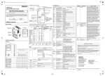
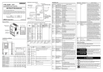
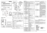
Standard Connection Diagram Parameter List DC reactor Regenerative Braking unit 3-phase 200 VAC Single-phase 200 VAC 3-phase 400 VAC TYPE JX-A@ Model X200 Series Inverter +1 + R/L1 (L1) S/L2 (/) T/L3 (N) INSTRUCTION MANUAL Thank you for purchasing JX inverter. Multi-function input To ensure safe operation, please be sure to read the safety precautions provided in this document along with all of the user manuals for the inverter. Please be sure you are using the most recent versions of the user manuals. Keep this instruction manual and all of the manuals in a safe location and be sure that they are readily available to the final user of the products. U/T1 V/T2 W/T3 JX Series User’s Manual 1 2 3 4 5 1 2 3 4 5 OMRON Corporation Power supply H Frequency reference O Common L OI Frequency reference (current) Frequency reference 1k ~ 2 kΩ I567-E1-01 NT305X-1 M L PCS 11 CM2 P24 Cat. No. d001 - Common Name Parameter No. Frequency reference (voltage) Type Terminal symbol Digital Operator For factory maintenance only Do not touch Communications connector Emergency shut off function selector (S8) Relay output terminal block OPE/485 communications selector (S7) Main circuit terminal block (output side) Main circuit R/L1,S/L2,T/L3 U/T1, V/T2, W/T3 Ground (symbol) D A2002-E, AB002-EF 80 67 155 143 95.5 Total RUN time 0 to 9999 d017 Power ON time monitor 0 to 9999 d018 Fin temperature monitor 0.0 to 200.0 d080 Fault frequency monitor 0 to 9999 d081 Fault monitor 1 (latest) d082 Fault monitor 2 d083 Fault monitor 3 Error code (condition of occurrence) → Output frequency → Output current → Internal DC voltage → RUN time → ON time C011 to C015 Multi-function input 1-5 operation selection 00:NO 01:NC d102 DC voltage monitor 0.0 to 999.9 C021 d104 Electric thermal monitor 0.0 to 100.0 Multi-function output terminal 11 selection F001 Output frequency setting / monitor Starting frequency to max. frequency C026 Relay output (AL1,AL2) function selection F002/F202 Acceleration time1/2nd acceleration time1 0.01 to 3000 F003/F203 Deceleration time1/2nd deceleration time1 0.01 to 3000 00:RUN(during RUN)/01:FA1(constant speed reached)/02:FA2(set frequency min. reached)/ 03:OL(overload warning)/04:OD(PID excessive deviation)/05:AL(alarm output)/06:Dc(disconnection defected)/07:FBV(PID FB value output)/08:NDc(Network error)/09:LOG(logic operation output)/10:ODc(communication option, disconnected)/43:LOC(light load defection) F004 Operator rotation direction selection 00:forward/01:reverse A001/A201 Frequency reference selection/2nd frequency reference selection 00:Digital Operator (volume)/01:Terminal/ 02:Digital Operator (F001)/ 03:Modbus communication/ 10:Frequency operation result AM Analog monitor output A2002 to A2007 AB002 to AB004 A2015 to A2037 A4004 to A4037 AB007 to AB022 A2055 to A2075 A4055 to A4075 M3.5 0.8 N·m (max. 0.9 N·m) M4 1.2 N·m (max. 1.3 N·m) M5 3.0 N·m (max. 3.3 N·m) AL0,AL1,AL2 M2.5 / 0.5 N·m (max. 0.6 N·m) — M4 A2004-E, AB004-EF 109.5 A2007-E 132.5 98 189 176 A2055-E, A2075-E, A4055-EF, A4075-EF 130.5 157.5 180 164 250 235 A002/A202 RUN command selec01:Terminal/02:Digital Operator/ tion/2nd RUN command 03:Modbus communication selection A003/A203 Base frequency/ 2nd base frequency A004/A204 Maximum frequency/ 30 to 400 2nd maximum frequency A005 O/OI selection 02: Switch between O/Volume via terminal AT 03: Switch between OI/Volume via terminal AT 04: O input only/05:OI input only A020/A220 Multi-step speed reference0/2nd multi-step speed reference0 0.0/Starting frequency to max. frequency Multi-step speed reference1~15 0.0/Starting frequency to max. frequency M5 Description Switches between the command setting and the data settings, and between the basic function mode and the expended function mode. Changes the set values, parameters and Commands. 167.5 RUN key Starts the operation. Forward/Reverse rotation depends on the 'F004' setting. STOP/RESET key Stops the operation. Functions as the Reset key if an error occurs. Enter key Enters and stores the data. Multi-function input5 selection/2nd multi-function input5 selection d016 Ground 1.9 D H1 C005/C205 Common Relay H H1 H Multi-function input4 selection/2nd multi-function input4 selection 0 to 600 Decrement key W1 C004/C204 Output voltage monitor * Hold down the Mode key for 3 seconds to jump to 'd001'. W Multi-function input3 selection/2nd multi-function input3 selection d013 W1 JX- C003/C203 Multi-function output M2 / 0.2 N·m (max. 0.25 N·m) Increment key Multi-function input2 selection/2nd multi-function input2 selection 0.00 to 9999 1000 to 3996 (at 10000 to 39960) (Output frequency × conversion factor of b086) AM,H,O,OI,L 5, 4, 3, 2,1,L, PCS,P24, CM2,11 W C002/C202 Output frequency monitor (after conversion) Status transition 110 F:forward/o:stop/r:reverse d007 Control circuit Mode key A2015-E, A2022-E, A2037-E A4007-EF, A4015-EF, A4022-EF, A4040-EF, AB015-EF, AB022-EF 0.0 to 999.9 Rotation direction monitor 00:FW(forward)/01:RV(reverse)/ 02:CF1(multi-step speed setting binary1)/ 03:CF2(multi-step speed setting binary2)/ 04:CF3(multi-step speed setting binary3)/ 05:CF4(multi-step speed setting binary4)/ 06:JG(jogging)/07:DB(external DC injection/ braking)/08:SET(2nd control)/09:2CH(2-step acceleration/deceleration)/11:FRS(free run stop)/12:EXT(external trip)/13:USP(USP function)/15:SFT(soft lock)/16:AT(analog input switch)/18:RS(reset)/19:PTC(thermistor input)/ 20:STA(3-wire start)/21:STP(3-wire stop)/22:F/ R(3-wire forward/reverse)/23:PID(PID enable/ disable)/24:PIDC(PID integral/reset)/ 27:UP(UP/DWN function accelerated)/ 28:DWN(UP/DWN function decelerated)/ 29:UDC(UP/DWN function data clear)/ 31:OPE(forward operator)/50:ADD(frequency addition)/51:F-TM(forced terminal block)/ 52:RDY(ready function)/53:SP-SET(special 2nd function)/64:EMR(emergency shut off)/ 255:No function 0.00 to 9999 (Valid when the PID function is selected.) -,+,+1 Dimensions A4004-EF, AB007-EF Output current monitor d003 Keys Installation and Wiring Multi-function input1 selection/2nd multi-function input1 selection PID feedback value monitor Option Name C001/C201 0.0 to 400.0 d002 * For AB@ @ @ , L1, /, N are indicated instead R/L1, S/L2, T/L3 respectively. Control circuit terminal block Output frequency monitor Monitor or data range Monitor or data range d004 Terminal symbols, Screw size and Tightening Torque Main circuit terminal block (input side) Function name Function name AL2 Relay output AL1 AL0 Common * Connect a single-phase 200 VAC input to terminals L1 and N. * Factory default settings for relay output are NC contact for AL1 and NO contact for AL2. Names of Parts Parameter No. 30 to max. frequency [A004/A204] C028 AM selection 00:Output frequency/01:Output current C031 Multi-function output Terminal 11 contact selection 00:NO contact at AL1, NC contact at AL2 01:NC contact at AL1, NO contact at AL2 C036 Relay output (AL1,AL2) contact selection H003/H203 Motor capacity selection/2nd motor capacity selection H004/H204 Motor pole number 2/4/6/8 selection/2nd motor pole number selection 200V class: 0.2 to 7.5 400V class: 0.4 to 7.5 SUITABILITY FOR USE A038 Jogging frequency 0.00/Strating frequency to 9.99 OMRON shall not be responsible for conformity with any standards, code, or regulations that apply to the combination of products in the customer’s application or use of the products. A039 Jogging stop selection 00:Free run on jogging stop 01:Deceleration stop on jogging stop 02:DC injection braking on jogging stop Take all necessary steps to determine the suitability of the product for the systems, machines, and equipment with which it will be used. Please know and observe all prohibitions of use apllicable to the products. A045/A245 Output voltage gain/ 2nd 20 to 100 output voltage gain A097 Acceleration pattern selection A098 Deceleration pattern selection b001 Retry selection A021 to A035 b002 Allowable momentary power interruption time 00:Line/01:S-shape curve 00: Alarm/01:0 Hz start 02: Frequency matching start 03: Trip after frequency matching deceleration stop NEVER USE THE PRODUCTS FOR AN APPLICATION INVOLVING SERIOUS RISK TO LIFE OR PROPERTY WITHOUT ENSURING THAT THE SYSTEM AS A WHOLE HAS BEEN DESIGNED TO ADDRESS THE RISKS, AND THAT THE OMRON PRODUCTS ARE PROPERLY RATED AND INSTALLED FOR THE INTENDED USE WITHIN THE OVERALL EQUIPMENT OR SYSTEM. See also product catalogs for Warranty and Limitations of Liability. Local support office: 0.3 to 25.0 b083 Carrier frequency 2.0 to 12.0 b084 Initialization selection 00:Clear the trip monitor 01:Initialize data 02:Clear and initialize b130 Overvoltage LAD stop function 00:Disable/01:Enable b131 Overvoltage LAD stop function level 200V class:330 to 395 400V class:660 to 790 OMRON Corporation Industrial Automation Company Control Devices Division H.Q. Motion Control Division Shiokoji Horikawa, Shimogyo-ku, Kyoto, 600-8530 Japan Tel: (81) 75-344-7173 Fax: (81) 75-344-7149 Regional Headquarters OMRON EUROPE B.V. Wegalaan 67-69-2132 JD Hoofddorp The Netherlands Tel. (31)2356-81-300 Fax: (31)2356-81-388 2-2-1 Nishikusatsu, Kusatsu-shi, Shiga, 525-0035 Japan Tel: (81) 77-565-5223 Fax: (81) 77-565-5568 [mm] Note: In the interest of product improvement, specifications are subject to change without notice. Printed in Japan Safety Precautions Precautions for Safe Use UL Cautions Wire Connectors Indications and Meanings of Safety Information Installation and Storage The warnings and instructions in this section summarizes the procedures necessary to ensure an inverter installation complies with Underwriters Laboratories guidelines. In this user's manual, the following precautions and signal words are used to provide information to ensure the safe use of the JX Inverter. The information provided here is vital to safety. Strictly observe theprecautions provided. Do not store or use the product in the following places. Field wiring connections must be made by a UL Listed and CSA certified ring lug terminal connector sized for the wire gauge being used. The connector must be fixed using the crimping tool specified by the connector manufacturer. Meanings of Signal Words @ DANGER @ CAUTION Indicates an imminently hazardous situation which, if not avoided, is likely to result in serious injury or may result in death. Additionally there may be severe property damage. Indicates a potentially hazardous situation which, if not avoided, may result in minor or moderate injury or in property damage. • Locations subject to direct sunlight. • Locations subject to ambient temperature exceeding the specifications. • Locations subject to relative humidity exceeding the specifications. • Locations subject to condensation due to severe temperature fluctuations. @ DANGER Turn off the power supply and implement wiring correctly. Not doing so may result in a serious injury due to an electric shock. Wiring work must be carried out only by qualified personnel. Not doing so many result in a serious injury due to an electric shock. Be sure to ground the unit. Not doing so may result in a serious injury due to an electric shock or fire. (200 V class: type-D grounding, 400 V class: type-C grounding) Do not remove the front cover during the power supply and 5 minutes after the power shut off. Doing so may result in a serious injury due to an electric shock. Do not operate the Operator or switches with wet hands. Doing so may result in a serious injury due to an electric shock. Inspection of the Inverter must be conducted after the power supply has been turned off. Not doing so may result in a serious injury due to an electric shock. The main power supply is not necessarily shut off even if the emergency shut off function is activated. Do not change wiring, mode change switches (S7, S8), optional devices or replace cooling fans while power is being supplied. Doing so may result in a serious injury due to an electric shock. @ CAUTION Do not connect resistors to the terminals (+1, +, –) directly. Doing so might result in a small-scale fire, heat generation or damage to the unit. Install a stop motion device to ensure safety. Not doing so might result in a minor injury. (A holding brake is not a stop motion device designed to ensure safety.) Be sure to use a specified type of braking resistor/regenerative braking unit. In case of a braking resistor, install a thermal relay that monitors the temperature of the resistor. Not doing so might result in a moderate burn due to the heat generated in the braking resistor/regenerative braking unit. Configure a sequence that enables the Inverter power to turn off when unusual overheating is detected in the braking resistor/regenerative braking unit. The Inverter has high voltage parts inside which, if short-circuited, might cause damage to itself or other property. Place covers on the openings or take other precautions to make sure that no metal objects such as cutting bits or lead wire scraps go inside when installing and wiring. Do not touch the Inverter fins, braking resistors and the motor, which become too hot during the power supply and for some time after the power shut off. Doing so may result in a burn. Take safety precautions such as setting up a molded-case circuit breaker(MCCB) that matches the Inverter capacity on the power supply side. Not doing so might result in damage to property due to the short circuit of the load. Do not dismantle, repair or modify this product. Doing so may result in an injury. Terminal (ring lug) Cable support • Use 75°C Cu wire only or equivalent. (For models:X200-002L(A2002), -004L(A2004), -007L(A2007), -022H(A4022), -040H(A4040), -055H(A4055), -075H(A4075), -002S(AB002), -004S(AB004)) Cable • Locations subject to corrosive or flammable gases. • Use 60°C Cu wire only or equivalent. (For models:X200-004H(A4004), -007H(A4007), -015H(A4015)) • Locations subject to exposure to combustibles. • Open Type Equipment. Circuit breaker and Fuse Size • Locations subject to dust (especially iron dust) or salts. • Suitable for use on a circuit capable of delivering not more than 100k rms symmetrical amperes, 240 V maximum when protected by Class CC, G, J or R fuses or circuit breaker having an interrupting rating not les than 100,000 rms symmetrical amperes, 240 volts maximum. (For models:200 V class) The Inverter's connections to input power must include UL Listed inverse time circuit breakers with 600 V rating, or UL Listed fuses as shown in the table below. • Locations subject to exposure to water, oil, or chemicals. • Locations subject to shock or vibration. Alert Symbols in this Document • Use 60/75°C Cu wire only or equivalent. (For models:X200-015L(A2015), -022L(A2022), -037L(A2037), -055L(A2055), -075L(A2075), -007S(AB007), -015S(AB015), -022S(AB022)) Transporting, Installation, and Wiring • Do not drop or apply strong impact on the product. Doing so may result in damaged parts or malfunction. • Do not hold by the front cover, but hold by the fins during transportation. • Do not connect an AC power supply voltage to the control input/output terminals. Doing so may result in damage to the product. • Suitable for use on a circuit capable of delivering not more than 100k rms symmetrical amperes, 480 V maximum when protected by Class CC, G, J or R fuses or circuit breaker having an interrupting rating not les than 100,000 rms symmetrical amperes, 480 volts maximum. (For models:400 V class) • Locations close to power lines. • Provide a separate holding brake if necessary. Ratings (A) Inverse timecircuit Breaker 10 004LFRF/SFEF (A2004/AB004) 015LFRF/SFEF (A2015/AB015) 20 • Solid state motor overload protection is provided in each model. • Integral solid state short circuit protection does not provide branch circuit protection. Branch circuit protection must be provided in accordance with the National Electric Code and any additional local codes or equivalent. 022LFRF/SFEF (A2022/AB022) 30 • Caution-Risk of electric shock, -capacitor discharge time is at least 5 minutes. 037LFRF (A2037) Terminal Tightening Torque and Wire Size The wire size range and tightening torque for field wiring terminals are presented in the tables below. Operation and Adjustment • Be sure to confirm the permissible range of motors and machines before operation because the inverter speed can be changed easily from low to high. 002LFRF/SFEF (A2002/AB002) Circuit Breaker/Fuse 15 • Do not connect any load other than a three-phase inductive motor to the U, V, and W output terminals. • Locations subject to strong magnetic fields. Inverter Model X200(JX-) 007LFRF/SFEF (A2007/AB007) • Maximum Surrounding Air Temperature 50°C or equivalent. • Locations subject to static electricity or other forms of noise. 200V class • Install device inn pollution degree 2 environment. • Be sure to tighten the screws on the terminal block securely. Wiring work must be done after installing the unit body. • Take sufficient shielding measures when using the product in the following locations. Not doing so may result in damage to the product. Input Voltage Motor Output Input Voltage 200 V class kW HP Inverter Model X200- (JX-) Power Terminal Wiring Size Range (AWG) 400V class Ft-lbs 50 004HFEF (A4004) Distribution Fuse (Class J) 3 007HFEF (A4007) 6 015HFEF (A4015) 10 002LFRF/SFEF (A2002/AB002) 0.4 1/2 004LFRF/SFEF (A2004/AB004) 0.75 1 007LFRF/SFEF (A2007/AB007) Precautions for Correct Use 1.5 2 015LFRF/SFEF (A2015/AB015) 12 040HFEF (A4040) 15 Installation 2.2 3 022LFRF/SFEF (A2022/AB022) 10 055HFEF (A4055) 20 3.7 5 037LFRF (A2037) 075HFEF (A4075) 25 5.5 7 1/2 055LFRF (A2055) 7.5 10 075LFRF (A2075 0.4 1/2 004HFEF (A4004) • Do not come close to the machine when using the error retry function because the machine may abruptly start when stopped by an alarm. 0.75 1 007HFEF (A4007) • Be sure to confirm the RUN signal is turned off before resetting the alarm because the machine may abruptly start. Set the rated current [Amperes] of the motor(s) with the above parameters. The setting range is 0.2 rated current to 1.0 rated current. 1.5 2 015HFEF (A4015) When two or more motors are connected to the Inverter, they cannot be protected by the electronic overload protection. Install an external thermal relay on each motor. 2.2 3 022HFEF (A4022) 4 5 040HFEF (A4040) 5.5 7 1/2 055HFEF (A4055) 7.5 10 075HFEF (A4075) • Mount the product vertically on a wall or on a DIN Rail (optional) with the product's longer sides upright. The material of the wall has to be noninflammable such as a metal plate. Main Circuit Power Supply • Confirm that the rated input voltage of the Inverter is the same as AC power supply voltage. Error Retry Function Non-Stop Function at Momentary Power Interruption • Do not come close to the machine when selecting reset in the non-stop function at momentary power interruption selection (b050) because the machine may abruptly start after the power is turned on. Operation Stop Command • Provide a separate emergency stop switch because the STOP Key on the Operator is valid only when function settings are performed. • When checking a signal during the power supply and the voltage is erroneously applied to the control input terminals, the motor may start abruptly. Be sure to confirm safety before checking a signal. Product Disposal • Comply with the local ordinance and regulations when disposing of the product. 400 V class 0.8 075LFRF (A2075 1/4 • Be sure to confirm safety before conducting maintenance, inspection or parts replacement. 0.6 (N·m) 40 0.2 Maintenance and Inspection 14 (75°C only) Torque 055LFRF (A2055) 0.9 8 1.2 2.3 3.0 Motor Overload Protection JX Inverters provide solid state motor overload protection, which depends on the proper setting of the following parameters: 16 (60°C only) 0.9 1.2 14 (75°C only) 10 • b012: electronic overload protection • b212: electronic overload protection, 2nd motor Conformance to EC Directives 2.3 3.0 • For earthing, selection of cable, and any other conditions for EMC-compliance, please refer to the manual for installation. • This is a class A product in residential areas it may cause radio interference, in which case the user may be required to take adequate measures to reduce interference. JX series Inverter has integrated EMC filter as shown below • 200 V class: EN61800-3 category C1 Torque Terminal Conector 022HFEF (A4022) Wiring Size Range (AWG) Ft-lbs (N·m) Logic and Analog connectors 30-16 0.16-0.19 0.22-0.25 Relay connector 30-14 0.37-0.44 0.5-0.6 • 400 V class: EN61800-3 category C2 OMRON Corporation Shiokoji Horikawa, Shimogyo-ku, Kyoto, 600-8530, Japan Omron Europe B.V. Wegalaan 67-69, NL-2132 JD Hoofddorp, The Netherlands