1
IBM TotalStorage™ Network Attached Storage 300
Model 326
User’s Reference
Release 2.5
GA27-4276-02
Note
Before using this information and the product it supports, be sure to read the general information in “Appendix A. Notices” on
page 127.
First Edition (June 2002)
This edition applies to Release 2.5 of the IBM 5195 TotalStorage Network Attached Storage 300 (Model 326, product
number 5195–326) and to all subsequent releases and modifications until otherwise indicated in new editions.
Order publications through your IBM representative or the IBM branch office servicing your locality. Publications are
not stocked at the address below.
IBM welcomes your comments. A form for reader’s comments is provided at the back of this publication. If the form
has been removed, you may address your comments to:
International Business Machines Corporation
Design & Information Development
Department CGF
PO Box 12195
Research Triangle Park, NC 27709–9990
U.S.A.
You can also submit comments on the Web at www.ibm.com/networking/support/feedback.nsf/docsoverall.
When you send information to IBM, you grant IBM a nonexclusive right to use or distribute the information in any
way it believes appropriate without incurring any obligation to you.
© Copyright International Business Machines Corporation 2002. All rights reserved.
US Government Users Restricted Rights – Use, duplication or disclosure restricted by GSA ADP Schedule Contract
with IBM Corp.
Contents
Figures
. . . . . . . . . . . . . . . . . . . . . . . . . . . vii
Tables . . . . . . . . . . . . . . . . . . . . . . . . . . . . ix
About this book . . . . . . . . . . . . . .
Who should read this book . . . . . . . . . . .
Frequently used terms . . . . . . . . . . . .
Publications . . . . . . . . . . . . . . . .
Descriptions of the Model 326 publications . . . .
Hardcopy publications shipped with the Model 326 .
Related publications . . . . . . . . . . . .
Web sites . . . . . . . . . . . . . . . . .
.
.
.
.
.
.
.
.
.
.
.
.
.
.
.
.
.
.
.
.
.
.
.
.
.
.
.
.
.
.
.
.
.
.
.
.
.
.
.
.
.
.
.
.
.
.
.
.
.
.
.
.
.
.
.
.
.
.
.
.
.
.
.
.
.
.
.
.
.
.
.
.
.
.
.
.
.
.
.
.
xi
xi
xi
xi
xii
xii
xii
xii
Chapter 1. Introduction . . . . . . . . . . . . . . . . . . . . . . 1
Roadmap for setting up and configuring the Model 326 . . . . . . . . . . 3
Cluster setup requirements . . . . . . . . . . . . . . . . . . . . . 6
Chapter 2. Configuration and administration tools . . . . . .
Using a keyboard, monitor, and mouse for setup and configuration .
Summary of configuration and administration tools . . . . . . .
Terminal Services and the IBM NAS Administration Console . . .
Installing Terminal Services . . . . . . . . . . . . . .
Connecting to the desktop through Terminal Services. . . . .
IBM NAS Administration console . . . . . . . . . . . .
Determining who is using the network-attached storage . . . .
IBM Advanced Appliance Configuration Utility. . . . . . . . .
Initial network adapter selection and connection to the IAACU .
IAACU Agent . . . . . . . . . . . . . . . . . . .
IAACU Console. . . . . . . . . . . . . . . . . . .
Universal Manageability Services . . . . . . . . . . . . .
System requirements . . . . . . . . . . . . . . . .
Starting UM Services . . . . . . . . . . . . . . . .
Windows 2000 for Network Attached Storage. . . . . . . . .
Telnet Server support . . . . . . . . . . . . . . . . .
SNMP support . . . . . . . . . . . . . . . . . . . .
. . . .
. . . .
. . . .
. . . .
. . . .
. . . .
. . . .
. . . .
. . . .
. . . .
. . . .
. . . .
. . . .
. . . .
. . . .
. . . .
. . . .
. . . .
. 9
. 9
. 9
. 12
. 12
. 12
. 13
. 13
. 13
. 14
. 15
. 15
. 21
. 21
. 22
. 23
. 24
. 24
Chapter 3. Getting started . . . . . . . . . .
Methods for setting up the Model 326 . . . . . .
Installing the IBM Advanced Appliance Configuration
Accessing Universal Manageability Services . . .
Initial setup and configuration . . . . . . . . .
Setting the date and time . . . . . . . . . .
Setting up the network . . . . . . . . . . .
.
.
.
.
.
.
.
.
.
.
.
.
.
.
.
.
.
.
.
.
.
.
.
.
.
.
.
.
.
.
.
.
.
.
.
25
25
25
26
26
27
27
Chapter 4. Setting up storage . . . . . . . . . . . . . . . .
Direct-managed method for managing the 5191 RAID Storage Controller
Starting Enterprise Management . . . . . . . . . . . . . . .
Starting Subsystem Management . . . . . . . . . . . . . . .
Changing storage-subsystem host type . . . . . . . . . . . .
Renaming storage subsystems . . . . . . . . . . . . . . .
Creating arrays and logical drives . . . . . . . . . . . . . .
Creating arrays and LUNs under the Storage Manager Application . .
Expanding the LUN . . . . . . . . . . . . . . . . . . .
.
.
.
.
.
.
.
.
.
.
.
.
.
.
.
.
.
.
.
.
.
.
.
.
.
.
.
29
29
31
32
32
32
32
32
33
© Copyright IBM Corp. 2002
. . .
. . .
Utility.
. . .
. . .
. . .
. . .
.
.
.
.
.
.
.
.
.
.
.
.
.
.
iii
Formatting the logical drives . . . . . . . . . . . . . . . . . . . 35
Chapter 5. Completing networking, clustering, and storage
Networking setup . . . . . . . . . . . . . . . . .
Configuring the interconnect (private) network adapter . .
Configuring the public local area connection . . . . . .
Verifying network connectivity and names resolution . . .
Checking or changing the network binding order . . . .
Joining a node to a domain . . . . . . . . . . . . .
Cluster setup . . . . . . . . . . . . . . . . . .
Configuring clusters . . . . . . . . . . . . . . . .
Configuring cluster state and properties . . . . . . . .
Setting up cluster resource balancing . . . . . . . .
Setting up failover . . . . . . . . . . . . . . . .
Creating users . . . . . . . . . . . . . . . . .
Defining UNIX users and groups . . . . . . . . . .
Creating clustered file shares (CIFS and NFS) . . . . .
Powering off and powering on the Model 326. . . . . .
Recovering from a corrupted Quorum drive . . . . . .
Before you add software ... . . . . . . . . . . . . .
Chapter 6. Managing and protecting the network
IBM Director . . . . . . . . . . . . . . .
Dependencies . . . . . . . . . . . . .
Hardware requirements . . . . . . . . . .
Director extensions . . . . . . . . . . .
Naming conventions . . . . . . . . . . .
Web-based access . . . . . . . . . . .
Disaster recovery . . . . . . . . . . . .
Software distribution . . . . . . . . . . .
Real-time diagnostics . . . . . . . . . .
Rack Manager and inventory enhancements . .
Dynamic NAS groups . . . . . . . . . .
NAS Web UI task . . . . . . . . . . . .
Electronic Service Agent (eSA) . . . . . . .
Predictive Failure Analysis. . . . . . . . .
For more information. . . . . . . . . . .
NAS Backup Assistant . . . . . . . . . . .
Restoring using the NT Backup panel . . . .
Persistent Images . . . . . . . . . . . . .
Global Settings . . . . . . . . . . . . .
Volume Settings . . . . . . . . . . . .
Persistent Images . . . . . . . . . . . .
Schedules . . . . . . . . . . . . . .
Restore Persistent Images . . . . . . . .
Disaster Recovery. . . . . . . . . . . .
Granting user access to persistent image files .
PSM notes . . . . . . . . . . . . . .
Microsoft Services for UNIX and NFS Support . .
Configuring Server for NFS . . . . . . . .
Antivirus protection . . . . . . . . . . . .
and
. .
. .
. .
. .
. .
. .
. .
. .
. .
. .
. .
. .
. .
. .
. .
. .
. .
. .
. .
. .
. .
. .
. .
. .
. .
. .
. .
. .
. .
access
. . .
. . .
. . .
. . .
. . .
. . .
. . .
. . .
. . .
. . .
. . .
. . .
. . .
. . .
. . .
. . .
. . .
storage
. . .
. . .
. . .
. . .
. . .
. . .
. . .
. . .
. . .
. . .
. . .
. . .
. . .
. . .
. . .
. . .
. . .
. . .
. . .
. . .
. . .
. . .
. . .
. . .
. . .
. . .
. . .
. . .
. . .
Chapter 7. Managing adapters and controllers . . . . . .
Managing Fibre Channel host bus adapters . . . . . . . .
Enabling communication between system management adapters
Enabling ISMP to RSA communication on a single machine .
iv
Model 326 User’s Reference
setup
. . .
. . .
. . .
. . .
. . .
. . .
. . .
. . .
. . .
. . .
. . .
. . .
. . .
. . .
. . .
. . .
. . .
.
.
.
.
.
.
.
.
.
.
.
.
.
.
.
.
.
37
37
37
38
39
39
40
40
41
41
42
42
43
43
47
49
50
51
.
.
.
.
.
.
.
.
.
.
.
.
.
.
.
.
.
.
.
.
.
.
.
.
.
.
.
.
.
.
.
.
.
.
.
.
.
.
.
.
.
.
.
.
.
.
.
.
.
.
.
.
.
.
.
.
.
.
.
.
.
.
.
.
.
.
.
.
.
.
.
.
.
.
.
.
.
.
.
.
.
.
.
.
.
.
.
.
.
.
.
.
.
.
.
.
.
.
.
.
.
.
.
.
.
.
.
.
.
.
.
.
.
.
.
.
.
.
.
.
.
.
.
.
.
.
.
.
.
.
.
.
.
.
.
.
.
.
.
.
.
.
.
.
.
.
.
.
.
.
.
.
.
.
.
.
.
.
.
.
.
.
.
.
.
.
.
.
.
.
.
.
.
.
.
.
.
.
.
.
53
53
54
54
55
55
55
56
56
57
57
58
58
58
59
59
59
60
61
62
62
62
63
64
64
68
68
72
73
75
.
.
.
.
.
.
.
.
.
.
.
.
.
.
.
.
.
.
.
.
.
.
.
.
77
77
78
80
Using the ISMP and RSA . . . . . . . . . . . . . . .
Enabling Ethernet adapter teaming . . . . . . . . . . . .
Intel adapters . . . . . . . . . . . . . . . . . . .
Alacritech 10/100 Quad-Port Ethernet adapter . . . . . . .
PRO/1000 XT Server adapter . . . . . . . . . . . . .
Adding a second IBM 5191 RAID Storage Controller Model 0RU .
RAID mirroring . . . . . . . . . . . . . . . . . . . .
Memory notes . . . . . . . . . . . . . . . . . . . .
Adding more engine memory to increase performance . . . .
Using the Recovery CD-ROM if you have added more processor
. . .
. . .
. . .
. . .
. . .
. . .
. . .
. . .
. . .
memory
Chapter 8. Troubleshooting. . . . . . . . . . . . . . . .
IBM 5187 Network Attached Storage Model 6RZ . . . . . . . .
Engine diagnostic tools overview . . . . . . . . . . . . .
Identifying problems using LEDs . . . . . . . . . . . . .
Engine troubleshooting charts . . . . . . . . . . . . . .
Power problems . . . . . . . . . . . . . . . . . . .
Recovering BIOS . . . . . . . . . . . . . . . . . . .
Replacing the battery . . . . . . . . . . . . . . . . .
Adapter troubleshooting and diagnostics . . . . . . . . . . .
Troubleshooting the integrated Ethernet adapter . . . . . . .
Troubleshooting the Gigabit Ethernet SX adapter . . . . . . .
Troubleshooting the Alacritech 10/100 Quad-Port Ethernet adapter
Troubleshooting the PRO/1000 XT Server adapter . . . . . .
Troubleshooting the ServeRAID-4Lx . . . . . . . . . . .
Troubleshooting the SCSI HVD 3570 adapter . . . . . . . .
Testing the Fibre Channel host adapter with FAStT MSJ . . . .
Testing the Integrated System Management Processor . . . . .
Testing the Remote Supervisor Adapter . . . . . . . . . .
Testing SCSI adapters . . . . . . . . . . . . . . . . .
IBM 3534 Fibre Channel Hub Model 1RU. . . . . . . . . . .
Hub diagnostics . . . . . . . . . . . . . . . . . . .
IBM 5191 RAID Storage Controller Model 0RU (storage controller) .
Replacing hot-swap drives . . . . . . . . . . . . . . .
IBM 5192 Storage Unit Model 0RU (storage unit) . . . . . . . .
.
.
.
.
.
.
.
.
.
.
.
.
.
.
.
.
.
.
.
.
.
.
.
.
.
.
.
.
.
.
.
.
.
.
.
.
.
.
.
.
.
.
.
.
.
.
.
.
.
.
.
.
.
.
.
.
.
.
.
.
.
.
.
.
.
.
.
.
.
.
.
.
.
.
.
.
.
.
.
.
.
.
.
.
.
.
.
.
.
.
80
81
81
82
83
83
84
84
84
84
. 85
. 85
. 85
. 86
. 89
. 91
. 92
. 93
. 96
. 96
. 100
. 101
. 102
. 103
. 107
. 108
. 109
. 110
. 111
. 111
. 112
. 113
. 116
. 118
Chapter 9. Using the Recovery and Supplementary CDs . . . . . . . . 123
Using the Recovery Enablement Diskette and Recovery CD . . . . . . . . 123
Using the Supplementary CD . . . . . . . . . . . . . . . . . . . 125
Appendix A. Notices . . . . . . . . . . . . . . . . . . . . . . 127
Trademarks. . . . . . . . . . . . . . . . . . . . . . . . . . 128
Appendix B. Getting help, service, and information .
Service support . . . . . . . . . . . . . . .
Before you call for service . . . . . . . . . . .
Getting customer support and service . . . . . . .
Getting help online: www.ibm.com/storage/support .
Getting help by telephone . . . . . . . . . .
.
.
.
.
.
.
.
.
.
.
.
.
.
.
.
.
.
.
.
.
.
.
.
.
.
.
.
.
.
.
.
.
.
.
.
.
.
.
.
.
.
.
.
.
.
.
.
.
.
.
.
.
.
.
129
129
130
130
130
131
Appendix C. Purchasing additional services . . . . . . . . . . . . 133
Warranty and repair services . . . . . . . . . . . . . . . . . . . 133
Appendix D. Engine POST and diagnostic program messages . . . . . 135
Power-on self-test (POST) . . . . . . . . . . . . . . . . . . . . 135
POST beep code descriptions . . . . . . . . . . . . . . . . . . 135
Contents
v
POST beep codes . . . . .
POST error messages. . . .
Event/error logs . . . . . .
Diagnostic program messages. .
Text messages . . . . . .
Starting the diagnostic programs
Viewing the test log. . . . .
Diagnostic error message tables
.
.
.
.
.
.
.
.
.
.
.
.
.
.
.
.
.
.
.
.
.
.
.
.
.
.
.
.
.
.
.
.
.
.
.
.
.
.
.
.
.
.
.
.
.
.
.
.
.
.
.
.
.
.
.
.
.
.
.
.
.
.
.
.
.
.
.
.
.
.
.
.
.
.
.
.
.
.
.
.
.
.
.
.
.
.
.
.
.
.
.
.
.
.
.
.
.
.
.
.
.
.
.
.
.
.
.
.
.
.
.
.
.
.
.
.
.
.
.
.
Appendix E. Setup procedures and diagnostics for the Fibre
General information. . . . . . . . . . . . . . . . .
Isolating a system fault . . . . . . . . . . . . . .
Removing power . . . . . . . . . . . . . . . . .
Service actions for error messages . . . . . . . . . .
Setting up partnering with the 3534 Fibre-managed hubs . . .
Setting IP Address of Fibre Hub and Fibre Switch . . . . .
Running diagnostics on the hub . . . . . . . . . . . .
Attaching to the serial port while the hub is off . . . . . .
Attaching to the serial port while the hub is on . . . . . .
Running diagnostics from a Telnet session on the Ethernet .
Diagnostic tests during POST . . . . . . . . . . . .
Diagnostic commands . . . . . . . . . . . . . . . .
Diagnostic command descriptions . . . . . . . . . . .
Error messages . . . . . . . . . . . . . . . . . .
Action codes and recommended actions . . . . . . . .
Diagnostic error message formats . . . . . . . . . .
Error message tables . . . . . . . . . . . . . . .
Channel
. . . .
. . . .
. . . .
. . . .
. . . .
. . . .
. . . .
. . . .
. . . .
. . . .
. . . .
. . . .
. . . .
. . . .
. . . .
. . . .
. . . .
Appendix F. Fast!UTIL options
Configuration settings . . . .
Host adapter settings . . .
Selectable boot settings . .
Restore default settings . .
Raw NVRAM data . . . .
Advanced adapter settings .
Extended Firmware Settings
Scan Fibre Channel Devices .
Fibre Disk Utility . . . . . .
Loopback Data Test . . . .
Select Host Adapter . . . .
.
.
.
.
.
.
.
.
.
.
.
.
.
.
.
.
.
.
.
.
.
.
.
.
.
.
.
.
.
.
.
.
.
.
.
.
.
.
.
.
.
.
.
.
.
.
.
.
.
.
.
.
.
.
.
.
.
.
.
.
.
.
.
.
.
.
.
.
.
.
.
.
.
.
.
.
.
.
.
.
.
.
.
.
.
.
.
.
.
.
.
.
.
.
.
.
.
.
.
.
.
.
.
.
.
.
.
.
.
.
.
.
.
.
.
.
.
.
.
.
.
.
.
.
.
.
.
.
.
.
.
.
.
.
.
.
.
.
.
.
.
.
.
.
.
.
.
.
.
.
.
.
.
.
.
.
.
.
.
.
.
.
.
.
.
.
.
.
.
.
.
.
.
.
.
.
.
.
.
.
.
.
.
.
.
.
.
.
.
.
.
.
.
.
.
.
.
.
.
.
.
.
.
.
.
.
.
.
137
140
145
145
146
146
148
148
Hub
. .
. .
. .
. .
. .
. .
. .
. .
. .
. .
. .
. .
. .
. .
. .
. .
. .
155
155
155
155
155
155
156
157
157
158
158
158
159
160
165
165
165
165
.
.
.
.
.
.
.
.
.
.
.
.
.
.
.
.
.
.
.
.
.
.
.
.
171
171
171
172
172
172
172
174
175
175
176
176
Appendix G. Customer Replaceable Unit (CRU) list . . . . . . . . . . 177
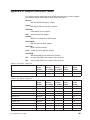
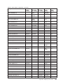
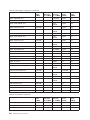
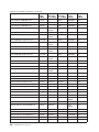
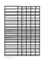
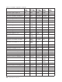
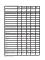
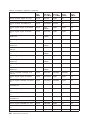
Appendix H. Adapter placement tables. . . . . . . . . . . . . . . 181
Glossary of terms and abbreviations . . . . . . . . . . . . . . . 203
Index . . . . . . . . . . . . . . . . . . . . . . . . . . . . 221
vi
Model 326 User’s Reference
Figures
1.
2.
3.
4.
5.
File share dependencies .
Diagnostics panel LEDs .
Boot block jumper location
Battery removal . . . .
Battery replacement. . .
© Copyright IBM Corp. 2002
.
.
.
.
.
.
.
.
.
.
.
.
.
.
.
.
.
.
.
.
.
.
.
.
.
.
.
.
.
.
.
.
.
.
.
.
.
.
.
.
.
.
.
.
.
.
.
.
.
.
.
.
.
.
.
.
.
.
.
.
.
.
.
.
.
.
.
.
.
.
.
.
.
.
.
.
.
.
.
.
.
.
.
.
.
.
.
.
.
.
.
.
.
.
.
.
.
.
.
.
.
.
.
.
.
.
.
.
.
.
.
.
.
.
.
.
.
.
.
.
.
.
.
.
.
.
.
.
.
.
.
.
.
.
.
47
88
93
95
95
vii
viii
Model 326 User’s Reference
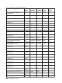
Tables
1.
2.
3.
4.
5.
6.
7.
8.
9.
10.
11.
12.
13.
14.
15.
16.
17.
18.
19.
20.
21.
22.
23.
24.
25.
26.
27.
28.
29.
30.
31.
32.
33.
34.
35.
36.
37.
38.
39.
40.
41.
42.
43.
44.
45.
46.
47.
Networking information worksheet for the public connection . . . . . . . . . . . . . . . 7
Summary of configuration and administration tools for the Model 326 . . . . . . . . . . . 10
Example of local area connection names and network adapter IP addresses . . . . . . . . . 39
Persistent image global settings . . . . . . . . . . . . . . . . . . . . . . . . . 62
Persistent image volume settings . . . . . . . . . . . . . . . . . . . . . . . . . 62
ISMP compared to the RSA . . . . . . . . . . . . . . . . . . . . . . . . . . . 79
Power supply LEDs . . . . . . . . . . . . . . . . . . . . . . . . . . . . . . 87
Descriptions of light-path diagnostics LEDs . . . . . . . . . . . . . . . . . . . . . 89
Engine troubleshooting symptoms and actions . . . . . . . . . . . . . . . . . . . . 90
Power error messages. . . . . . . . . . . . . . . . . . . . . . . . . . . . . 91
Integrated Ethernet adapter troubleshooting chart . . . . . . . . . . . . . . . . . . . 97
10/100 PCI Ethernet adapter troubleshooting chart . . . . . . . . . . . . . . . . . . 98
Gigabit Ethernet SX adapter troubleshooting chart . . . . . . . . . . . . . . . . . . 100
Alacritech 10/100 Quad-Port Ethernet adapter LED definitions. . . . . . . . . . . . . . 101
PRO/1000 XT Server adapter troubleshooting chart . . . . . . . . . . . . . . . . . 102
ServeRAID-4Lx problems and actions. . . . . . . . . . . . . . . . . . . . . . . 106
SCSI HVD 3570 adapter troubleshooting chart . . . . . . . . . . . . . . . . . . . 108
HUB front panel LED status indicators . . . . . . . . . . . . . . . . . . . . . . 111
Hub POST tests. . . . . . . . . . . . . . . . . . . . . . . . . . . . . . . 112
Hub offline and online tests . . . . . . . . . . . . . . . . . . . . . . . . . . 113
Storage controller troubleshooting . . . . . . . . . . . . . . . . . . . . . . . . 113
Storage unit troubleshooting table . . . . . . . . . . . . . . . . . . . . . . . . 118
Supplementary CD directories . . . . . . . . . . . . . . . . . . . . . . . . . 126
IBM Web sites for help, services, and information . . . . . . . . . . . . . . . . . . 129
POST beep codes . . . . . . . . . . . . . . . . . . . . . . . . . . . . . . 137
POST no-beep codes . . . . . . . . . . . . . . . . . . . . . . . . . . . . 139
POST error messages . . . . . . . . . . . . . . . . . . . . . . . . . . . . 140
Diagnostic error messages . . . . . . . . . . . . . . . . . . . . . . . . . . . 148
Hub POST diagnostic tests . . . . . . . . . . . . . . . . . . . . . . . . . . 158
Hub action codes . . . . . . . . . . . . . . . . . . . . . . . . . . . . . . 165
Hub diagnostic error messages . . . . . . . . . . . . . . . . . . . . . . . . . 166
Hub system error messages . . . . . . . . . . . . . . . . . . . . . . . . . . 169
Host adapter settings . . . . . . . . . . . . . . . . . . . . . . . . . . . . . 171
Advanced adapter settings . . . . . . . . . . . . . . . . . . . . . . . . . . . 172
Extended firmware settings . . . . . . . . . . . . . . . . . . . . . . . . . . 174
RIO operation modes. . . . . . . . . . . . . . . . . . . . . . . . . . . . . 174
Connection options . . . . . . . . . . . . . . . . . . . . . . . . . . . . . 174
5186-36U Rack . . . . . . . . . . . . . . . . . . . . . . . . . . . . . . . 177
5197–6RZ Engine . . . . . . . . . . . . . . . . . . . . . . . . . . . . . . 177
5191–0RU RAID Storage Controller . . . . . . . . . . . . . . . . . . . . . . . 178
5192–0RU Storage Unit . . . . . . . . . . . . . . . . . . . . . . . . . . . . 178
3534–1RU Hub . . . . . . . . . . . . . . . . . . . . . . . . . . . . . . . 179
One-adapter configuration . . . . . . . . . . . . . . . . . . . . . . . . . . . 181
Two-adapter configuration . . . . . . . . . . . . . . . . . . . . . . . . . . . 181
Three-adapter configuration . . . . . . . . . . . . . . . . . . . . . . . . . . 182
Four-adapter configuration . . . . . . . . . . . . . . . . . . . . . . . . . . . 184
Five-adapter configuration . . . . . . . . . . . . . . . . . . . . . . . . . . . 189
© Copyright IBM Corp. 2002
ix
x
Model 326 User’s Reference
About this book
This book provides information necessary to configure and administer the IBM 5195
TotalStorage Network Attached Storage 300, Model 326.
Hereafter, the IBM 5195 TotalStorage Network Attached Storage 300, Model 326, is
referred to as the Model 326.
Who should read this book
This book is for Model 326 administrators.
The Model 326 administrator should have experience in at least the following skills,
or have access to personnel with experience in these skills:
v Microsoft® Windows® and Windows Advanced Server
v Networking and network management
v Disk management
v SAN management
v General technologies of the product (such as Microsoft Cluster Service, Services
for UNIX®, storage, RAID, and so on)
v Critical business issues (such as backup, disaster recovery, security)
Frequently used terms
This document contains certain notices that relate to a specific topic. The caution
and danger notices also appear in the multilingual Safety Information on the
Documentation CD that came with the appliance. Each notice is numbered for easy
reference to the corresponding notices in the Safety Information.
The following terms, used within this document or within the Safety Information,
have these specific meanings:
Term
Definition in this document
Attention
These notices indicate possible damage to programs, devices, or
data. An attention notice is placed just before the instruction or
situation in which damage could occur.
Caution
These notices indicate situations that can be potentially hazardous
to you. A caution notice is placed just before descriptions of
potentially hazardous procedure steps or situations.
Danger
These notices indicate situations that can be potentially lethal or
extremely hazardous to you. A danger notice is placed just before
descriptions of potentially lethal or extremely hazardous procedure
steps or situations.
Notes
These notices provide important tips, guidance, or advice.
Publications
The latest versions of the following product publications are available in softcopy at:
http://www.ibm.com/storage/support/nas
© Copyright IBM Corp. 2002
xi
Descriptions of the Model 326 publications
The Model 326 library consists of the following publications:
v Hardware Installation Guide
This book describes hardware physical specifications, electrical specifications,
cabling, environmental specifications, and networking specifications for installing
the Model 326.
v User’s Reference
This book describes such operational and administrative activities as:
– Using the configuration utilities
– Administering the Model 326
– Troubleshooting
– Using the Recovery and Supplementary CDs
Hardcopy publications shipped with the Model 326
The following publications are shipped in hardcopy and are also provided in
softcopy (PDF) form at:
http://www.ibm.com/storage/support/nas
v IBM 5195 TotalStorage Network Attached Storage 300 Installation Guide,
GA27-4275
v Release Notes
This document provides any changes that were not available at the time this
book was produced.
Note that the User’s Reference is provided in softcopy only.
Related publications
The following publications contain additional information about the Model 326:
v Network Attached Storage 300 Installation Guide GA27–4275
v Network Attached Storage 300 Service Guide GA27–4277
v UM Services User’s Guide (on the Documentation CD that came with the
appliance)
Additional information on Universal Manageability Services, IBM Director, and
Advanced System Management is located on the Documentation CD that came with
the appliance.
Web sites
The following Web site has additional and up-to-date information about the Model
326:
v http://www.ibm.com/storage/nas/
A highly recommended Web site: for the latest troubleshooting guidance and
symptom-fix tip information, go to the IBM support Web site at:
v http://www.ibm.com/storage/support/nas
This site contains additional information, gathered from field experience, not
available when this document was developed.
xii
Model 326 User’s Reference
Chapter 1. Introduction
This appliance offers a storage solution for both Windows, UNIX, and UNIX-like
environments, including mixed Windows-UNIX environments that enable Windows
and UNIX clients and servers to share the same Fibre Channel storage. With the
Model 326 integrated storage appliance, your enterprise will gain a scalable,
network-attached storage device that delivers state-of-the-art systems management
capabilities and task-optimized operating system technology. The Model 326
provides your enterprise with increased performance, storage capacity, and
functionality.
This appliance has been developed for workgroup or department environments with
file-serving requirements across Windows and UNIX clients, e-business, and
numerous applications. In addition, this device supports Ethernet LAN environments
with large or shared end-user workspace storage, remote running of executables,
remote user data access, and personal data migration.
This new machine replaces the IBM 5195 Model 325. Enhancements provided by
the Model 326 include:
v Greater granularity in configuring storage size
v Twice the maximum storage size
v More options in configuring Ethernet connections
v More options for tape backup
The Model 326 is a two-node appliance server and features:
v One Rack 36U (with two Power Distribution Units)
v Two engines (IBM 5187 Network Attached Storage Model 6RZ), each with:
– Dual 1.133 GHz processors
– 1 GB memory
– Two redundant 270-watt power supplies
– Fibre Channel adapter
– Four high-performance PCI adapter slots for plugging in optional 10/100 and
Gigabit Ethernet, Fibre Channel, and management adapters. (Communication
between the two engines takes place through an integrated 10/100 Mbps
Ethernet port on each engine’s planar board.)
v Two Fibre Channel hubs
v One Fibre Channel RAID storage controller (with a minimum of three and up to
ten 36.4 or 73.4 GB hot-swappable hard disk drives)
v Optional storage:
– An additional RAID storage controller
– Maximum of seven storage expansion units, each populated with three to ten
36.4 or 73.4 GB hot-swappable hard disk drives
v A 1GB memory upgrade
v Optional adapters:
– Single-port 10/100 Ethernet adapter
– Quad-port 10/100 Ethernet adapter
– Gigabit Ethernet adapter
– ServeRAID-4Lx adapter
– Remote Supervisor Adapter
– Dual-port Fibre Channel Host-Bus Adapter
© Copyright IBM Corp. 2002
1
In addition, the Model 326 provides clustering and failover protection with its two
nodes. This high-availability design helps protect against appliance failure and
increases uptime to provide continuous access to data.
Note: Throughout this book, information about the Model 326 node and engine
applies to both its nodes and engines.
The preloaded software is based on the Windows Powered OS operating system,
which is very similar to Microsoft® Windows® 2000 Advanced Server. Preloaded
software includes:
Microsoft Windows 2000 for Network Attached Storage
Enables remote administration of the appliance using a Web-based
graphical user interface (GUI).
Microsoft Cluster Service
Provides clustering support and failover.
Microsoft Windows Terminal Services
Enables remote administration of the appliance using its Windows desktop.
Microsoft Services for UNIX
Provides file access to UNIX and UNIX-based clients and servers through
the Network File System (NFS) protocol. Note that the Model 326 supports
Linux and other platforms that employ NFS.
IBM Director Agent and Universal Manageability Server Extensions
Provides system management support based on industry standards (in
conjunction with the IBM Director console application as well as other
management software).
IBM Advanced Appliance Configuration Utility agent
Supports management through the IBM Advanced Appliance Configuration
Utility console application (supports aggregate Web-based management of
all of your IBM appliances).
IBM FAStT Storage Manager for Windows 2000
Provides RAID configuration management for the external RAID controllers
and storage expansion units.
ServeRAID Manager RAID Configuration and Monitoring
Provides configuration tools and RAID management of the ServeRAID-4Lx
adapter.
IBM FAStT Management Suite Java (MSJ)
Provides diagnostics for the Fibre Channel adapters.
Intel PROSet II
Provides diagnostics for the Intel Ethernet adapters.
Alacritech® SLICuser
Provides diagnostics for the quad-port Ethernet adapter.
Columbia Data Products® Persistent Storage Manager (PSM)
Provides 250 persistent images of customer data and enables full online
backup of system with Microsoft’s backup applications.
Tivoli® Storage Manager Client
Provides data backup and archive support (in conjunction with Tivoli
Storage Manager Server).
2
Model 326 User’s Reference
Roadmap for setting up and configuring the Model 326
A suggestion for first-time users . . .
Your understanding of the Model 326 and your ability to use it will be greatly
enhanced if you first proceed to the NAS Setup Navigator tutorial.
The NAS Setup Navigator is a distillation of the tasks you will need to
complete to set up and configure the Model 326 and get it up and running.
The Navigator not only presents information on functions and features -- such
as clustering -- but also allows you to enable the functions and features.
After you have become familiar with the Model 326, you can refer to this book
for more details.
The following roadmap presents the requirements and instructions for setting up
and configuring the Model 326. Following these directions and referring to the
appropriate sections of this book will help you in this task.
Prerequisites
v A domain controller must exist on the network and a login ID must be
defined for each node to log on. Each node must join the same domain.
v All Windows shared disks must be defined as basic. Windows 2000
dynamic disks are not supported.
v A Quorum drive must be available to both nodes and have the same
drive letter on each node.
v All disks shared between the two cluster nodes must have the same
drive letter.
v All shared storage must be defined as NTFS and be on primary
partitions.
v Compression cannot be enabled on any disk partition.
v Each node must have one private and one public adapter.
Cluster setup requirements
See “Cluster setup requirements” on page 6.
Configuration and administration tools
The Model 326 is a network-attached storage appliance that has several
different methods of configuration depending on your environment.
First, determine how you will manage the device. You can manage the
Model 326 in “headless” mode or with a keyboard, display, and mouse
directly attached to each node. See “Using a keyboard, monitor, and mouse
for setup and configuration” on page 9 for information on managing this
device using a keyboard, display, and mouse. For “headless” management
of the Model 326, you can use one of the following tools:
v Terminal Services, for remote configuration and management from
another device on the network
v Universal Manageability Services (UMS) for management through a Web
browser
v Windows 2000 for NAS, a Web-based GUI for those not familiar with the
Windows desktop
v IBM Advanced Appliance Configuration Utility (IAACU) for setup and
configuring multiple devices or other appliances on a single network
Chapter 1. Introduction
3
After you determine how you will manage the Model 326, you can begin
setup and configuration of the device.
For more information on configuration and administration tools, see
“Chapter 2. Configuration and administration tools” on page 9.
Step 1 - Initial network setup
Configure both nodes to enable access over the network. The general steps
to do this are given below. More details are given in “Chapter 3. Getting
started” on page 25.
1. Use Dynamic Host Configuration Protocol (DHCP) or static addressing
to set up one public network connection in each node.
a. If you are operating with a keyboard, display, and mouse, set up a
public network connection to access the device.
b. If you are operating in a headless environment, use one of the
following methods:
v If DHCP is installed and the IP address requested can be
determined, you can use DHCP for initial setup, but you should
change this address to static later in the configuration.
v If you have multiple appliances or cannot determine the DHCP
address, you can install the IAACU utility to identify appliances
and define IP addresses. The tool will also allow you to set static
addresses.
2. Complete the steps in “Setting the date and time” on page 27 and
“Setting up the network” on page 27.
Step 2 - Define shared storage and setup partitions
The Model 326 comes with preconfigured shared storage spanning nine
disks. The storage is formatted as an array, at RAID-level 5, consisting of
the following logical unit numbers (LUNs):
v A LUN of 500 MB, for the Quorum drive (drive letter G)
v A second LUN, composed of the remaining space and used as a shared
drive with one built-in hot spare
To use this default, preconfigured storage, validate all storage areas and
determine that the drive letters are the same on each node.
Otherwise, from one of the two nodes, define all storage arrays using
Storage Manager and then set up Windows partitions as defined in
“Chapter 4. Setting up storage” on page 29.
Attention: When you set up the shared storage, you must configure the
storage on one node only. During the setup of shared storage, leave the
joining node powered off.
Step 3 - Complete network setup and cluster installation
1. Power on either node. (This becomes the first node.)
2. Set up the first node:
a. Networking setup
See “Networking setup” on page 37. Note the cautionary statement
at the beginning of that section.
b. Domain setup
See “Joining a node to a domain” on page 40.
4
Model 326 User’s Reference
3. Power off the first node.
4. Power on the other node (the joining node).
5. Set up the joining node:
a. Networking setup
See “Networking setup” on page 37.
b. Shared storage setup
For the joining node, the only part of this step that you must
complete is assigning drive letters on the shared storage; make sure
that the drive letters are the same as those on the first node.
Also, if you have trouble with the Fibre Channel connection, you can
use the steps in “Testing the Fibre Channel host adapter with FAStT
MSJ” on page 108 to diagnose the problem.
c. Domain setup
See “Joining a node to a domain” on page 40.
d. Power off the joining node.
6. Power on the first node and complete “Cluster setup” on page 40.
7. Power on the joining node and complete “Cluster setup” on page 40.
For more information on network setup and cluster installation, see
“Chapter 5. Completing networking, clustering, and storage access setup”
on page 37.
Step 4 - Cluster administration
At this point you can add users, file shares, and complete other
configuration tasks to improve operations of the Model 326 in a cluster
environment.
1. Add users (see “Creating users” on page 43).
2. Add file shares (see “Creating clustered file shares (CIFS and NFS)” on
page 47). Note that you must configure Server for NFS before NFS file
sharing can be used.
For more information on cluster administration, see “Configuring clusters” on
page 41.
Step 5 - Additional functions
Additional functions are available for backup, persistent images, and adding
more storage areas. It is recommended that after you complete the setup
and configuration procedures, you use the Persistent Storage Manager
Disaster Recovery option (“Disaster Recovery” on page 64) or other method
to back up the system configuration in the event of a failure.
Also, it is imperative to use the system shutdown procedure described
in “Powering off and powering on the Model 326” on page 49 to ensure
system integrity.
For more information, see “Chapter 6. Managing and protecting the network
and storage” on page 53.
Chapter 1. Introduction
5
Cluster setup requirements
Before you configure the Model 326 nodes for clustering, ensure that the following
requirements are met:
Network requirements
v A unique NetBIOS cluster name.
v You will need at least seven static IP addresses: five for the node and
cluster setup, and two for each file share served by the cluster. A formula
for the number of static IP addresses is: 5 + (2 x number_of_file shares).
The IP addresses required for node and cluster setup are:
– At least three unique, static IP addresses for the public network: one
for each node (for client access through the PCI NIC adapter) and
one for the cluster itself (the administration IP address).
Table 1 on page 7 shows a summary of the networking information
necessary for the public connection.
– Two static IP addresses for the cluster interconnect on a private
network or crossover, through the onboard Ethernet adapter. The
default IP addresses for the private network adapters are 10.1.1.1 for
the first node in the cluster, and 10.1.1.2 for the node that joins the
cluster. (The top node in the Model 326 is considered the first node,
and the bottom node is considered the joining node.)
Notes:
1. If you are not the system administrator, contact that person for the
applicable IP addresses.
2. Each node in a cluster must join the same domain and be able to
access a Primary Domain Controller (PDC) and DNS server, but it is not
required that the nodes log into the domain.
3. Each node in the cluster must have at least two network adapters: at
least one for the public network and the other for the private
interconnect.
Shared disk requirements
v All shared disk arrays and devices, including the quorum disk, must be
physically attached to a shared storage bus.
v All shared disks must be configured as basic (not dynamic) disks.
v All shared disks must have the same drive letter on each node.
v All partitions on these disks must be formatted with NTFS.
v All partitions on these disks must also be Primary Partitions.
v Compression must not be enabled.
Powering off and powering on the Model 326
The clustering function requires special considerations when you need to
power off and power on the Model 326. See “Powering off and powering on
the Model 326” on page 49 for details.
6
Model 326 User’s Reference
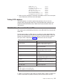
Table 1. Networking information worksheet for the public connection
Cluster component
Cluster
Information needed
Cluster name:
IP address:
Subnet mask:
First node
Computer name (example: IBM5195–23H1234):
IP address:
Subnet mask:
Gateway:
Preferred DNS:
WINS server (optional):
Joining node
Computer name:
IP address:
Subnet mask:
Gateway:
Preferred DNS:
WINS server (optional):
Domain to join
Domain name:
Chapter 1. Introduction
7
8
Model 326 User’s Reference
Chapter 2. Configuration and administration tools
Attention
Changing the preloaded software configuration of this product, including
applying or installing unauthorized service packs or updates to preinstalled
software, or installing additional software products that are not included in
either the preloaded image or on the Supplementary CD, might not be
supported and could cause unpredictable results. For updated compatibility
information, refer to the IBM web site:
http://www.storage.ibm.com/nas
To correct problems with a preloaded software component, back up your user
and system data. Then, use the Recovery CD to restore the preloaded
software image.
The Model 326 appliance comes with the following configuration programs that you
can use to configure and administer the appliance:
v
v
v
v
Terminal Services Client
IBM Advanced Appliance Configuration Utility (IAACU)
Universal Manageability Services
Windows 2000 for Network Attached Storage
This chapter describes these tools in general and then in detail.
Using a keyboard, monitor, and mouse for setup and configuration
It is highly recommended that you directly attach a keyboard, monitor, and mouse to
the Model 326 when performing these tasks:
v Initially setting up and configuring the device
v Changing or adding to RAID arrays (for example, adding a new array with
Storage Manager, adding a new RAID controller, or adding a storage expansion
unit)
v Troubleshooting the device
Summary of configuration and administration tools
There are several ways to set up and administer the Model 326. Table 2 on page 10
suggests which tool to use for specific functions, but does not list all options or
combinations. The administrator’s training level or preferences might determine an
alternate approach from that suggested in the table.
© Copyright IBM Corp. 2002
9
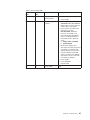
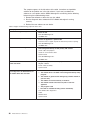
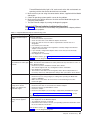
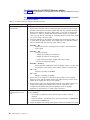
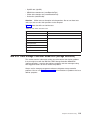
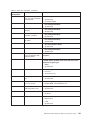
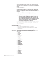
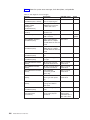
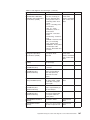
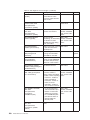
Table 2. Summary of configuration and administration tools for the Model 326
Administration tool
Main functions
Windows Domain Controller (not NAS Users and user groups can be defined and authenticated by the Windows
appliance)
Domain Controller, although this is not required.
IBM Advanced Appliance
Configuration Utility (IAACU)
Access a headless Model 326 node, particularly for the initial setup of the
network connectivity. (Alternatively, you can attach a keyboard, mouse,
display to each node of the Model 326.) IAACU enables you to:
v Set time, date, and initial network connectivity parameters
v Access to Windows 2000 for NAS GUI, Terminal Services (NAS Desktop),
and Universal Manageability Services
Windows 2000 for NAS GUI
Provides ease-of-use administration, but not all the capabilities of Terminal
Services and IBM NAS Administration. The GUI enables you to:
v Configure networking connectivity, private (for clustering) and public LAN
connections
v Create and format logical drives
v Join domains
v Set up access permissions and disk quotas for CIFS, NFS, HTTP, FTP,
and Novell® NetWare® shares
v Use Persistent Storage Manager
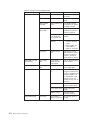
IBM NAS desktop and IBM NAS
Admin program, through a Terminal
Services session or a
directly-connected keyboard and
monitor
Provides in-depth administration of all aspects of Model 326. Provides all of
the Windows 2000 for NAS GUI functions above, plus the ability to:
v Use NAS Backup Assistant, or NT Backup and Restore wizard
v Learn detailed inventory information about hardware, OS, and so on, using
Universal Manageability Services
v RAID configuration through Storage Manager:
– Create RAID arrays and LUNs
– Add additional RAID or storage enclosure after initial purchase
– Rename storage subsystems
v Cluster administration:
– Set up cluster
– Define failover for each volume
– Manually fail over cluster resources
– Set up cluster resource balancing by assigning preferred node
v Diagnose system problems:
– Check Ethernet adapters using PROSet II and 10/100 Quad-Port
Ethernet adapter using SLICuser
– Check Fibre Channel card using FAStT MSJ
– Check RAID subsystem using Storage Manager
Disaster Recovery
Restores a previously saved PSM image of the system partition to a failed
machine. This restores all configuration information on the failed node. You
create the recovery boot diskette from the PSM tools in the Windows for
2000 NAS GUI.
Recovery CD Set
Reinstalls the software to the original state as shipped on the machine;
however, does not restore configuration information (configuration changes
you applied to the original shipped configuration are lost). You must first boot
with the Recovery Enablement Diskette, and then reboot with the Recovery
CD. To create the Recovery Enablement Diskette, run
enablement_disk_x.y.exe (where x.y are the version number of the disk),
located on the Supplementary CD. You will be prompted to insert a blank disk
into drive a:.
Integrated System Management
Processor (ISMP) configuration
program
Configures the ISMP that is integrated on the engine planar board.
Remote Supervisor Adapter (RSA)
configuration program
Configures the optional RSA.
10
Model 326 User’s Reference
Terminal Services Client
The Terminal Services Client, when installed on a workstation that is
attached to the same network as the Model 326, enables you to remotely
administer the appliance using the Model 326 desktop. If you are familiar
with administrative tasks using a Windows desktop, you can use Terminal
Services.
See “Terminal Services and the IBM NAS Administration Console” on
page 12 for more information.
IBM Advanced Appliance Configuration Utility (IAACU)
The IBM Advanced Appliance Configuration Utility (IAACU) aids in setting
up and reconfiguring the network configuration on your appliances. The
IAACU agent works with the IAACU Console to automatically detect the
presence of appliances on the network.
After the appliance is detected by the IAACU Console, you can use the
IAACU to:
v Set up and manage the network configuration for the appliance, including
assigning the IP address, default gateway, network mask, and DNS
server to be used by the appliance. (See the note in “Setting up the
network” on page 27, regarding the Ethernet adapter that is integrated on
the planar board.)
v Start Universal Manageability Services on the appliance, enabling you to
perform advanced systems-management tasks.
See “IBM Advanced Appliance Configuration Utility” on page 13 for more
information.
Universal Manageability Services
Universal Manageability Services (UM Services) provides point-to-point
remote management of client systems using a Web browser. Use UM
Services to:
v Learn detailed inventory information about your computers, including
operating system, memory, network cards and hardware.
v Track your computers with features such as power management, event
log, and system monitor capabilities.
v Integrate with Tivoli Enterprise, Tivoli NetView®, Computer Associates
Unicenter, Microsoft SMS, and Intel® LANDesk Management Suite.
In addition, you can link to Windows 2000 for Network Attached Storage
and Terminal Services from UM Services.
See “Universal Manageability Services” on page 21 for more information.
Windows 2000 for Network Attached Storage
The Model 326 provides a Web-based GUI, Microsoft Windows 2000 for
Network Attached Storage (Windows 2000 for NAS). Using Windows 2000
for NAS, you navigate through administrative task categories by clicking the
appropriate tabs and then selecting a task from that category.
See “Windows 2000 for Network Attached Storage” on page 23 for more
information.
Chapter 2. Configuration and administration tools
11
Terminal Services and the IBM NAS Administration Console
If you are familiar with Windows operating systems, you can use Terminal Services.
In some cases, you must use Terminal Services to complete administrative tasks.
You can access Terminal Services in two ways:
1. Through the UM Services browser, as described in step 3 on page 23.
2. By using the Terminal Services Client software.
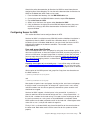
Installing Terminal Services
To use the Terminal Services Client, complete the following steps to install it on the
remote workstation and connect to the Model 326 appliance:
1. Insert the Supplementary CD into the workstation CD-ROM drive.
2. Select Start → Run.
3. In the Open field, type (with quotation marks)
"x:\Terminal Services Client\Disk 1\setup.exe"
where x is the drive letter assigned to the CD-ROM drive.
4. Click OK to begin the Terminal Services Client Setup program.
5. Accept the defaults in each window that opens or refer to the Microsoft
Windows documentation for more instructions.
6. When the Terminal Services Client Setup program completes, ensure that the
workstation has network-connectivity to the NAS appliance so that you can
administer the appliance.
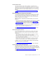
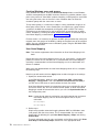
Connecting to the desktop through Terminal Services
To connect to Terminal Services from your workstation, do the following:
1. Click Start → Programs → Terminal Services → Terminal Services Client.
2. In the Server field, select the computer name of the appropriate Model 326. If
that Model 326 is not listed, enter the IP address or the computer name of the
Model 326. The computer name is predefined as IBM5195-xxxxxxx, where
xxxxxxx is the serial number located in the lower right corner of the bezel on the
front of the appliance. If you have changed the computer name from the
predefined value, use that name instead.
Note: Although you can do so, it is recommended that you not change the
default computer name to avoid the chance of propagating
misidentification through the system. And, if you are using IBM Director
to manage your appliance, and you change the default name, the default
name continues to appear in IBM Director.
3. For Size, select a screen size in which the Model 326 desktop will appear. It is
recommended that you choose a size other than full screen.
4. Click Connect to start the Terminal Services Client session. A user login window
appears.
5. Log in. Type Administrator in the Username field, type password in the
Password field, and then click OK to log in. After you log in, you can begin
using Terminal Services Client to configure and manage the Model 326, as if a
keyboard, mouse, and monitor were directly attached to it. The Model 326
desktop contains a shortcut, titled IBM NAS Admin, to a special console, the
IBM NAS Administration console.
12
Model 326 User’s Reference
IBM NAS Administration console
The IBM NAS Administration console includes all the standard functions provided by
the standard Computer Management console available on any Windows 2000
desktop, plus the following functions specific to the Model 326:
v Cluster Administration (see “Configuring clusters” on page 41)
v Storage Manager (see “Chapter 4. Setting up storage” on page 29)
v These advanced functions (see “Chapter 6. Managing and protecting the network
and storage” on page 53):
– Advanced System Management Integrated Adapter and Remote Supervisor
Adapter
– FAStT MSJ
– NAS Backup Assistant
– Persistent Storage Manager
Determining who is using the network-attached storage
Occasionally, you might want to know who is using the network-attached storage.
To determine this information:
1. Start a Windows Terminal Services session from the administrator’s console to
the Model 326.
2. Click the IBM NAS Admin icon on the desktop.
3. In the left pane, click File Systems → Shared Folders → Sessions.
4. The users currently using the storage are displayed. To close those sessions,
use a right-click. Before you close a session, notify the user that you are going
to close the session by clicking Start → Programs → Accessories → Command
Prompt, and then issuing the net send hostname messagetext command.
IBM Advanced Appliance Configuration Utility
Note: Although you can do so, it is recommended that you not change the default
computer name of your NAS appliance to avoid the chance of propagating
misidentification through the system. Also, The IBM Advanced Appliance
Configuration Utility depends on the original name to function.
The IBM Advanced Appliance Configuration Utility (IAACU) helps you to set up and
reconfigure the network configuration on the Model 326 appliance, as well as other
IBM appliances. The IAACU agent, preinstalled on the Model 326 appliance, works
with the IAACU Console, a Java-based application that is installed on a
network-attached system. You can use the IAACU as a systems-management
console to automatically detect the presence of Model 326 appliances on the
network. After the Model 326 appliance is detected by the IAACU Console, use the
IAACU to set up and manage the appliance’s network configuration, including
assigning the IP address, default gateway, network mask, and DNS server to be
used by the appliance. You can also use the IAACU to start Universal Manageability
Services (UM Services) on the appliance, enabling you to perform more advanced
systems-management tasks.
For networks that are not currently running DHCP servers, the IAACU is useful for
automatically configuring network settings for newly added appliances, such as the
Model 326.
However, networks with DHCP servers will also benefit from using the IAACU
because it enables you to reserve and assign the appliance IP address in an
orderly, automated fashion. Even when you use DHCP and do not reserve an IP
Chapter 2. Configuration and administration tools
13
address for the appliance, you can still use the IAACU to discover appliances and
to start UM Services Web-based systems management.
Notes:
1. The IAACU configures and reports the TCP/IP settings of the first adapter
(excluding the integrated Ethernet controller that is used for the interconnection
of the two engines) on each appliance. The “first” adapter is defined by its
position: if there is an adapter in slot 2, it is the first adapter; if there is an
adapter in slot 3, it is the first adapter.
Be sure to connect the first adapter to the same physical network as your
systems-management console. You can do this in one of two ways:
v Manually configure the network adapter to be on the same subnetwork as the
systems-management console.
v Create a Family that assigns the network adapter to the same subnetwork as
the systems-management console. See “Using Families and Groups in the
Tree View” on page 17 for more details. Note that the values for Min IP
address, Max IP address, Subnet Mask, and Default Gateway must be in the
same range that the IAACU is configured.
2. The IAACU must be running to configure newly installed appliances
automatically.
3. The system running the IAACU Console automatically maintains a copy of its
database (ServerConfiguration.dat) in the Advanced Appliance Configuration
Station installation directory. To remove previous configuration data, close the
IAACU, delete this file, and then restart the utility. This deletes all previously
configured Families. However, the IAACU will automatically discover connected
appliances and their network settings.
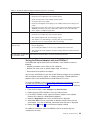
Initial network adapter selection and connection to the IAACU
Unlike the limited number of network adapter placement options in the previous
release, in this release there are an increased number of network adapter types
and/or locations from which you can connect. Assuming you have a keyboard and
monitor attached, perform the following steps to take into account the new adapter
placement options:
1. Decide which adapter will be used to connect to the IAACU, and connect the
appropriate cable type.
2. Open the Network and Dial-up Connections panel. (From the desktop, right-click
My Network Places, and select Properties.)
3. Determine the connection name of the adapter you have selected to use. Move
the mouse cursor over the adapter name, and a description of the adapter type
will appear. If this is inconclusive, right-click the adapter, and select Properties.
Under the General tab, click the Configure button. The line which contains the
location information will provide the adapter’s slot location. For example,
Location 1 means the adapter is in PCI slot number 1. Close the adapter
properties panel.
4. On the Network and Dial-up Connections menu bar, select Advanced and then
Advanced Settings. From the Connections menu, select the adapter’s
connection name. Then using the down arrow, move the selection down to the
next-to-last position in the list. (The last entry in the list should be the remote
access connections, shown as the telephone icon.) Save your changes by
clicking OK.
5. The IAACU will now detect the appliance using the adapter you have just
enabled.
14
Model 326 User’s Reference
IAACU Agent
The IAACU agent is preinstalled on the Model 326 appliance.
After you connect the Model 326 to your network, the IAACU agent automatically
reports the appliance serial number and type, the MAC address of its onboard
Ethernet controller, and whether DHCP is in use by the appliance. Furthermore, it
reports the host name, primary IP address, subnet mask, primary DNS server
address, and primary gateway address if these are configured on the system.
Note: The IAACU agent periodically broadcasts the appliance IP settings. To
prevent the service from broadcasting this data periodically, stop the
iaaconfig service.
IAACU Console
The IAACU Console is a Java application that you install on one system in your
network for use as a systems-management console. For information on how to
install the IAACU Console, see Table 23 on page 126.
Note: The IAACU creates a private database that is specific to the IP subnetwork
to which it is attached. Therefore, do not install it on more than one
systems-management console residing on the same IP subnetwork.
The IAACU Console enables you to:
v Automatically discover Model 326 appliances, as well as other IBM appliances
that run the IAACU agent and are attached to the same physical subnet as the
IAACU Console.
v Use a GUI-based application to configure the appliance network settings.
Use the IAACU to assign network parameters such as IP addresses, DNS and
gateway server addresses, subnet masks, and host names.
v Group discovered appliances into function-specific Families. Appliances are
added to a Family based on the appliance type. Appliances that perform the
same function appear in the same Family.
v Start UM Services Web-based systems-management console.
Launch UM Services on your appliances and perform advanced
systems-management tasks on a selected appliance with a single mouse click.
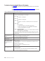
The IAACU Console is divided into two panes:
v The Tree View Pane
The Tree View Pane, located on the left side of the IAACU Console window,
presents a list of all discovered Model 326 appliances and includes any Families
you have previously defined. The Tree View Pane also includes groups for
appliances that do not fit any of the defined Families, that were not configured
using the IAACU, or that have IP addresses that conflict with other devices on
your network. When you click any item in the Tree View, information about that
item (and any items that are nested below that item in the tree view) appears in
the Information Pane.
v The Information Pane
The Information Pane, located on the right side of the IAACU Console, displays
information about the item that is currently selected in the Tree View Pane. The
information that appears in the Information Pane varies depending on the item
that is selected. For example, if you select the All Appliances item from the Tree
View Pane, the Information Pane displays configuration information (IP settings,
Chapter 2. Configuration and administration tools
15
host name, serial number, and so on) about each of the Model 326 appliances
that have been discovered by the IAACU Console. However, if you select a
Family, the Information Pane displays information about the Family settings for
the selected Family.
The IAACU Console also features the following menus:
File
Use the File menu to import or export the IAACU Console configuration
data, to scan the network, or to exit the program.
Family
Use the Family menu to add or delete Families, or to move Families up or
down in the tree view.
Appliance
Use the Appliance menu to remove a previously discovered appliance from
a Family or group, and to add an appliance to the first matching Family in
the tree view.
Help
Use the Help menu to display product information.
Discovering Model 326 Appliances
Any Model 326 appliance, or other IBM appliance, that is running and is connected
to the same subnet as the system running the IAACU Console is automatically
discovered when you start the IAACU Console. Discovered appliances appear in
the IAACU Console tree view (in the left pane of the IAACU Console window). Each
appliance appears in two locations in the tree view:
v Every discovered appliance is listed in the tree view under All Appliances.
v Each discovered appliance also appears in one of the following sections of the
tree view:
– In a Family
If the discovered appliance fits the requirements of a Family, it will
automatically appear as part of a Family.
Notes:
1. If a discovered appliance fits the requirements of more than one Family, it
is automatically added to the first appropriate Family that is listed in the
tree view, starting from the top of the tree. For information on how to move
appliances between families, see “Using Families and Groups in the Tree
View” on page 17.
2. If the Model 326 cannot be discovered by the IAACU console, check the
IP and subnet addresses of the Model 326 and the computer that is
running the IAACU console.
– In the Orphaned Appliances group
If the discovered appliance does not fit a previously configured Family, it is
placed in the Orphaned Appliances group.
– In the Orphaned Externally Configured Appliances group
Appliances that are running the IAACU agent, but that have a network
configuration that was not set by the IAACU agent or console, will appear in
the Orphaned Externally Configured Appliances group. If an appliance is
contained in the Orphaned Externally Configured Appliances group, you can
use the Adopt By First Matching Family function to add it to a previously
defined Family. For more information, see “Using the Adopt by First Matching
Family function” on page 19.
16
Model 326 User’s Reference
Using Families and Groups in the Tree View
Families are important elements of the IAACU. They specify the parameters that the
IAACU uses to automatically categorize discovered appliances and to configure
them with the appropriate network settings. Family rules are defined solely by
appliance type or purpose. Each Family can contain only one type of appliance.
The only way to automatically apply predetermined network settings to newly
installed and discovered appliances is to create and use Families.
Appliances that match the rules criteria for a Family group can be automatically
configured to use predefined network settings. A Family can be configured to allow
appliances to use DHCP to configure their IP settings, or can be defined to
automatically assign IP settings (such as primary gateway and DNS server
addresses, assigning an IP address from a specified IP address range, and
specifying a subnet mask). Host names for discovered appliances can also be
defined so that they are allocated using either a prefix or appliance serial number.
The IAACU is not the only way to configure network settings. For example, network
settings can be configured using Terminal Services for Windows or by attaching a
keyboard and mouse to the appliance and using Windows Control Panel. If the
appliance network settings have been configured by a method other than using the
IAACU, the appliance will be discovered by the IAACU and it will be added to an
appropriate Family, if one exists. Appliances that have been configured using a
method other than the IAACU for which no appropriate family exists will appear in
the Orphaned Externally Configured Appliances group.
The Tree View Panel contains the following items:
v All Appliances
Every discovered appliance is listed in the tree view under All Appliances.
v Families
The Families group in the Tree View Pane shows all Families that have been
defined, with appliances that have already been assigned to each Family nested
beneath the Family name in the tree view. Families are defined by appliance
purpose, so all appliances that appear in a given family are of the same type. If
you select a Family from the Tree View Pane, a description of the Family and the
rules that are used to define the selected Family appear in the Information Pane.
If you select an appliance from a Family in the Tree View Pane, the selected
appliance network settings appear in the Information Pane.
If you are not using DHCP, the IAACU automatically assigns one IP address per
appliance, using available addresses within the range defined in the Family rules.
When the IP address range for the Family has been exhausted, the IAACU
automatically searches for other Families that have rules matching the appliance
being configured. If a matching Family with an available address is found, the
appliance will automatically be assigned to the Family that has available IP
addresses. This enables you to define multiple Families, each of which uses a
set of noncontiguous IP address ranges.
When an appliance is discovered on the network, the IAACU automatically
searches all previously defined Families, starting with the first Family listed in the
Families tree view and moving downward. Appliances are automatically added to
the first defined Family that matches the appliance purpose. Therefore, the order
in which Families appear is important. To adjust this search order, right-click a
Family and then select Move Up or Move Down to adjust its position within the
Families list.
v Orphaned Appliances
Chapter 2. Configuration and administration tools
17
Any discovered appliances that have been configured using the IAACU but that
do not meet the rules for any existing Family are automatically added to the
Orphaned Appliances group.
v Orphaned Externally Configured Appliances
Any discovered appliance that has been configured without using the IAACU tool
and that does not meet the rules for any existing Family is automatically added to
the Orphaned Externally Configured Appliances group. Appliances configured
without the IAACU that meet the rules for any existing Family are automatically
added to the matching Family.
To add an Orphaned Externally configured Appliance to an appropriate Family
that was created after the orphaned appliance was discovered, right-click the
orphaned appliance and select Adopt by First Matching Family. For more
information, see “Using the Adopt by First Matching Family function” on page 19.
Note: The IAACU does not change manually configured network settings of
discovered appliances. If the manually configured IP and Subnet
addresses fit an existing Family, the IAACU will place that appliance into
that Family, but does not change any other settings (such as host name,
DNS, or gateway addresses).
v Conflicting Network Addresses
Any discovered appliance that has the same IP address as a previously
discovered appliance will be listed in the Conflicting Network Addresses group.
Creating a Family
To create a Family:
1. Select Create Family from the Family menu.
The IAACU Family Setup window opens.
2. Select Appliance Family Rules.
The Appliance Family Rules determine what purpose an appliance must serve
to be included in the Family. Select one of the following values:
v IBM TotalStorage NAS Appliances
v IBM xSeries 130 and 135
3. Type the name that will be used for this Family in the Family Name field.
4. Specify network resources to be used by members of the Family.
You can use the IAACU to assign network resources for members of this
Family, or you can use a DHCP server to assign network resources.
v To use the IAACU to assign network resources, clear the Use DHCP check
box and fill in the following fields:
Min IP Address
The lowest IP address in a range of IP addresses that can be
assigned to an appliance that is a member of this Family.
Max IP Address
The highest IP address in a range of IP addresses that can be
assigned to an appliance that is a member of this Family.
Subnet Mask
The subnet mask value that will be used by appliances that are
members of this Family.
Default Gateway
The IP address of the default gateway that will be used by appliances
that are members of this Family (optional).
18
Model 326 User’s Reference
DNS
The IP address of the DNS server that will be used by appliances
that are members of this Family (optional).
v To use a DHCP server to assign network resources, select the Use DHCP
check box. This allows a DHCP server on your network to assign an IP
address and subnet mask and to specify the default gateway address and
address of the DNS server that will be used by appliances that are members
of this Family.
5. Select a Host Name Assignment Type.
The Host Name Assignment Type enables you to automatically specify a Host
Name that members of this Family will use. You can select one of the following
Host Name Assignment Types:
No Allocation
Assigns no preconfigured host name format to appliances that are
members of this Family.
Use Serial Number
Uses the serial number of the discovered appliance as a host name for
the appliance.
Use Prefix Name
Uses a user-specified prefix, along with an incremental number for each
appliance, for the host name of each appliance that is a member of this
Family. Type the prefix in the Host Name Prefix field.
6. Click Finish to save this Family.
Removing Appliances from Families
Use the Remove Appliance function to delete an appliance from the IAACU Console
database and view panel. Removing an appliance that is no longer in use allows
the IP address that was assigned to the appliance to be allocated to another
appliance. You can also remove an appliance from a family and then rescan the
network to add it to an appropriate Family that appears higher in the Tree View
pane.
To remove an appliance, right-click the appliance, and then select Remove
Appliance from the pop-up menu.
v If the IAACU cannot communicate with the selected appliance (because, for
example, it has been removed from the network or has failed), the appliance is
removed immediately.
v If the IAACU can communicate with the selected appliance, you are prompted to
confirm removal of the appliance before the appliance removal task is completed.
This helps prevent accidental removal of an active and functional appliance.
Using the Adopt by First Matching Family function
Use this function to:
v Add an Orphaned Externally Configured Appliance to an appropriate Family.
Appliances that have been configured without using the IAACU tool and that do
not meet the rules for any existing Family are automatically added to the
Orphaned Externally Configured Appliances group. If, after the orphaned
appliance is discovered, you create a Family that is appropriate for the orphaned
appliance, right-click the orphaned appliance and select Adopt by First
Matching Family to move the appliance from the Orphaned Externally
Configured Appliances group to the newly created Family.
v Move an appliance from one Family to another appropriate Family that occurs
higher in the list of previously defined Families. If there is more than one
appropriate Family for a newly discovered appliance, it automatically appears in
Chapter 2. Configuration and administration tools
19
the first appropriate Family in the list of Families. If you want to move a
discovered appliance from one appropriate Family to another appropriate Family:
1. Right-click the Family that you want the appliance moved to.
2. Select Move Up in List to move the selected Family up in the list of families.
Repeat steps 1 and 2 until the Family that you want to add the appliance to
appears above the Family that currently contains the appliance.
3. Right-click the appliance that you want to move to another Family and then
select Adopt by First Matching Family.
20
Model 326 User’s Reference
Universal Manageability Services
Universal Manageability Services (UM Services) is a Windows application that
functions as both a stand-alone management tool for the system it is installed on
and a client to IBM Director.
As a Director Client, it receives and sends information to the Director Server as
controlled from the IBM Director Console.
As a stand-alone tool, it provides a Web-browser based interface and a Microsoft
Management Console (MMC) interface, where you can view the system status,
perform certain management tasks and configure alerts.
The Universal Manageability Services (UM Services) GUI enhances the local or
remote administration, monitoring, and maintenance of IBM systems. UM Services
is a lightweight client that resides on each managed computer system. With UM
Services, you can use a Web browser and UM Services Web console support to
inventory, monitor, and troubleshoot IBM systems on which UM Services is
installed.
This “point-to-point” systems-management approach, in which you use a Web
browser to connect directly to a remote-client system, enables you to effectively
maintain IBM systems without requiring the installation of additional
systems-management software on your administrator console.
In addition to point-to-point systems-management support, UM Services also
includes support for UM Services Upward Integration Modules. These modules
enable systems-management professionals who use any supported
systems-management platform (including Tivoli Enterprise, CA Unicenter TNG
Framework, and Microsoft Systems Management Server [SMS]) to integrate
portions of UM Services into their systems-management console. Because it was
designed to use industry-standard information-gathering technologies and
messaging protocols, including Common Information Model (CIM), Desktop
Management Interface (DMI), and Simple Network Management Protocol (SNMP),
UM Services adds value to any of these supported workgroup or enterprise
systems-management platforms.
You can use UM Services to perform the following tasks:
v View detailed information about your computers, including operating system,
memory, network cards, and hardware.
v Track your computers with features such as power management, event log, and
system monitor capabilities.
v Upwardly integrate with Tivoli Enterprise, Tivoli Netview, Computer Associates
Unicenter, Microsoft SMS, and Intel LANDesk Management Suite.
Complete documentation on how to use UM Services is included on the
Documentation CD that came with the appliance.
System requirements
The UM Services client is preinstalled on the Model 326 appliance. However, you
must have a Web browser installed on your systems-management console. It is
recommended that you set Microsoft Internet Explorer 5.x (or later) as the default
browser.
Chapter 2. Configuration and administration tools
21
Notes:
1. You must install the optional Java Virtual Machine (VM) support to access a
client system running UM Services.
2. If you reinstall Internet Explorer after installing UM Services, you must reapply
the Microsoft VM update. The UM Services client requires Microsoft VM Build
3165 or later. Download the latest Microsoft VM from www.microsoft.com/java
3. If you install UM Services before you install MMC 1.1 (or a later version), you
will not have an icon for Microsoft Management Console in the IBM Universal
Manageability Services section of the Start menu.
Starting UM Services
You can use IAACU or Terminal Services Client to configure the network setting
remotely, or you can attach a keyboard and mouse to your appliance and configure
the Network settings using the Windows Control Panel. After you have configured
the network settings for your appliance, you are ready to use UM Services.
To start UM Services:
1. Start a Web browser and then, in the Address or Location field of the browser,
type:
http://ip_address:1411
where ip_address is the IP address of the Model 326, and then press Enter.
Or, type:
http://computer_name:1411
where computer_name is the computer name of the Model 326. The computer
name is predefined as: IBM5195-xxxxxxx, where xxxxxxx is the serial number
located in the lower right corner of the bezel on the front of the appliance.
If you have changed the computer name from the predefined value, use that
name instead. A user log in window appears.
2. Type Administrator in the User Name field, and type password in the Password
field. You can leave the Domain field blank. Make sure the “Save this password
in your password list” check box is not selected, and then click OK.
Note: To ensure system security, change the Administrator password from
“password” to something else. After you do, or if you create another user
in the Administrator group in the future, use your new
username/password combination instead of the default
username/password combination.
The first time you connect, you might be prompted to install XML and Swing
components. Follow the on-screen instructions to install these components and
then close and restart Internet Explorer before you proceed.
You are now connected to the Model 326 through UM Services. In addition to
the standard UM Services functionality, the appliance includes functionality for
administering the appliance, available from the Appliances tab in the left pane of
the UM Services browser. The default view (in the right pane of the UM
Services browser) when you connect to the appliance is Windows 2000 for
NAS. The other selectable view in the Appliance tab is Windows 2000 Terminal
Services, which displays a Terminal Services Web Connection page.
22
Model 326 User’s Reference
3. To start Windows 2000 for NAS, click Administer this server appliance in the
right pane of the UM Services browser. To connect to the Model 326 and
manage it as though you were running Terminal Services Client from the
desktop, select Terminal Services in the Appliance tab of the UM Services
browser, and then follow the instructions for connecting to the Model 326 using
Terminal Services described in “Terminal Services and the IBM NAS
Administration Console” on page 12.
Launching UM Services from the configuration utility
You can use the IAACU to launch UM Services on the Model 326 appliances.
Note: The selected appliance must be running Universal Manageability (UM)
Services as a UM Services client. Also, the systems-management console
(the system that is running the IAACU Console) must use a Web browser
that is supported for use with UM Services. If you have not used UM
Services from this system, you must install several plug-ins before
proceeding.
To use the IAACU Console to start UM Services on an appliance:
1. Click the appliance in the IAACU Console Tree View Pane.
When you select the appliance from the tree view, information about the
selected appliance appears in the Information Pane.
2. Click the Start Web-Based Management button.
Your default Web browser starts, loading the UM Services browser
automatically.
3. Log in to the UM Services browser. Refer to Step 2 on page 22 for login
instructions.
For more information on using UM Services to manage your appliances, see the
Universal Manageability Services User’s Guide, included on the Documentation CD
that came with the appliance.
Windows 2000 for Network Attached Storage
While you can perform most administrative tasks using Windows 2000 for NAS, you
must use Terminal Services Client for some advanced tasks. See “Terminal
Services and the IBM NAS Administration Console” on page 12 for more
information.
Task categories available to you through Windows 2000 for NAS include:
v Status
v
v
v
v
v
Network
Disks
Users
Shares
Maintenance
v Controller
To start Windows 2000 for NAS, use one of these methods:
v UM Services, described in step 3.
v Web browser, by entering http://ip_address:8099 or http://computer_name:8099
and then logging on to the Model 326.
Chapter 2. Configuration and administration tools
23
v Model 326 desktop while using Terminal Services Client and starting a browser.
You can access online help for Windows 2000 for NAS in two ways:
1. Click the Help button at the top of any Web page. This displays a table of
contents that you can navigate to find help for any Windows 2000 for NAS task.
2. Click the question mark (?) button at the top of any Web page. This displays
context-sensitive help for the task you are currently performing.
Telnet Server support
CAUTION:
When you Telnet to another machine, your user name and password are sent
over the network in plain, unencrypted, text.
The Model 326 includes Telnet server capability. The Telnet server provides limited
administrative capability. This can be useful in cases where you need to remotely
administer the Model 326, but do not have access to a Windows-based workstation
(from which you could remotely administer the appliance through a supported Web
browser or Terminal Services Client).
To access the Model 326 from any Telnet client, specify the IP address or host
name of the Model 326, then log in using an ID and password (defined on the
Model 326) with administrative authority. From the command line, you can issue
DOS-like commands (such as dir and cd), and some UNIX-like commands (such
as grep and vi). You can launch some applications, but only character-mode
applications are supported.
By default, the Telnet server is disabled. To enable the Telnet server, from the
Windows 2000 for NAS user interface, go to the Network task group, then select
Telnet. On the Telnet Administration Configuration page, select the Enable Telnet
access to this appliance check box. If you do not require Telnet access to the Model
326, then it is recommended that you leave the Telnet server disabled.
SNMP support
Support for the Simple Network Management Protocol (SNMP) is enabled. To
manage the Model 326 from an SNMP-capable management application, you must
install the management information base (MIB) files for various components of the
Model 326 on the management application workstation, so that the application can
recognize those SNMP elements (values, alerts, and so on) supported by the
components.
24
Model 326 User’s Reference
Chapter 3. Getting started
This chapter gives details to set up the initial communication to the Model 326 to
enable setup and configuration. These instructions refer specifically to a base
configuration as shipped and do not cover the setup of additional storage units,
which can be purchased separately.
Note: You must follow these procedures for both nodes.
Methods for setting up the Model 326
The following sections detail how to set up the Model 326. You must first ensure
that the network recognizes the new appliance. Which method you should use
depends on several conditions:
v In “headless” mode (without a keyboard, monitor, and mouse directly attached to
the unit), use one of the following methods:
– IBM Advanced Appliance Configuration Utility
If you have multiple appliances or cannot determine the DHCP address, install
the IAACU to identify appliances and define IP addresses. The tool also
allows you to set static addresses.
If you are using this method, proceed with “Installing the IBM Advanced
Appliance Configuration Utility”.
– Windows Terminal Services
If DHCP is installed and the IP address requested can be determined, use this
method for initial setup, but you should change the address to static later in
the configuration. This condition is most appropriate when using Windows
Terminal Services for operation of the Model 326.
If you are using this method, proceed with “Initial setup and configuration” on
page 26.
v The use of a keyboard, display, and mouse is most appropriate when there is a
single or few appliances in the network and you use static setup and definition.
If you are using this method, proceed with “Initial setup and configuration” on
page 26.
Installing the IBM Advanced Appliance Configuration Utility
These instructions assume that you have installed and powered on the appliance
according to the installation guide procedures. You are now ready to install the
IAACU Console application from the Supplementary CD.
Install the Advanced Appliance Configuration console application from the
Supplementary CD onto a Windows NT 4.0 or Windows 2000 workstation that is
attached to the same IP subnetwork to which the appliance is attached.
Note: The IAACU creates a private database that is specific to the IP subnetwork
to which it is attached. Therefore, do not install it on more than one systems
management console residing on the same IP subnetwork.
For information on how to install the IAACU Console, see Table 23 on page 126.
After you install the Advanced Appliance Configuration console application, the
following steps will take you to the point where you can administer the appliance.
© Copyright IBM Corp. 2002
25
1. Start the Advanced Appliance Configuration console application by clicking its
icon.
2. On the left pane of the Advanced Appliance Configuration console, select the
appliance to administer. Initially, the appliance name is IBM5195-serial number;
the serial number is located in the lower right corner of the bezel on the front of
the appliance.
3. Click the Start Web Management button to start the Universal Manageability
(UM) Services browser. This will open a separate Web browser window.
4. Proceed to “Accessing Universal Manageability Services”.
For more information on the IAACU, see “IAACU Console” on page 15.
Accessing Universal Manageability Services
1. You will be prompted to authenticate with the administrative user name
(“Administrator”) and password (initially “password,” but you can change it later;
note that the password is case-sensitive, but the user name is not).
If this is the first time you have accessed the UM Services browser (on any
appliance) from this workstation, you will also be prompted to install the Swing
and XML Java libraries in your Web browser. You can download these libraries
from the Model 326 through the network link.
2. The UM Services browser starts. In the left pane, Microsoft Windows 2000 for
Network Attached Storage is automatically selected on the Appliance tab. In the
right pane, Windows 2000 for Network Attached Storage starts.
3. Again, you are prompted to authenticate with the administrative user name and
password.
4. Click Administer this server appliance to bring up the Microsoft Windows
2000 for Network Attached Storage GUI.
5. You are now ready to begin administering the appliance. Details for this task are
described in “Initial setup and configuration”.
Initial setup and configuration
This section provides details on the initial setup and configuration of the Model 326.
Note that if you are administering the Model 326 without a keyboard, monitor, and
mouse (“headless” mode), you can use one of two methods:
v Terminal Services, which provides full administrative function. (See “Terminal
Services and the IBM NAS Administration Console” on page 12.)
v Windows 2000 for Network Attached Storage, which provides a subset of the full
administrative function in Terminal Services. (See “Windows 2000 for Network
Attached Storage” on page 23.)
In general, you administer the appliance by adjusting information contained in the
following task groups:
Note: In this example, you access the task groups through the Windows 2000 for
Network Attached Storage Web-based GUI.
v “Setting the date and time” on page 27
v “Setting up the network” on page 27
26
Model 326 User’s Reference
Although you can modify multiple appliance and network attributes in each task
group, the information given here is the minimum you need to know to administer
the appliance and network.
You can find more information on administration elsewhere in this book and in the
online help.
You can access these task groups in one of three ways:
1. Click the Home tab and then select the task group link.
2. Click the top tab associated with that task group.
3. Click the Back button on the browser until you arrive Home and then select the
task group link.
Setting the date and time
To change the date and time, click Date and Time. (Remember that you can also
access all of these task groups by clicking the titled tabs at the top of the page.)
The Set Date and Time page appears, allowing you to adjust information as
necessary.
Setting up the network
Note: All appliances have an initial default user name of “administrator” and
password of “password.”
As part of the Network task group, you can change the administrator password and
(optionally) you can configure the properties of each network interface that resides
on the appliance.
To change the administrator password, click Change Administrator Password.
The Change Administrator Password page appears, allowing you to change the
password. Note the warning on the page that any information that you enter can be
viewed by others on the network. To prevent others from seeing your information,
set up a secure administration Web site as described in the online help.
To change IP addresses, click on Interfaces. The Network Adapters on Server
Appliance page appears. Use this page primarily to change IP addresses from
dynamic (DHCP, which is the system default) to static.
Note: During the initial setup, you should configure the nonplanar Ethernet adapter
only. The Model 326 engine uses the Ethernet adapter that is integrated on
the planar board as the interconnect private network for clustering.
If you want to use an Ethernet adapter other than the default Ethernet
adapter (in slot 2) as the network interface to be attached to the subnet, then
you can change the order of precedence later with the Windows Networking
Properties option. The order of precedence for the initial configuration is: PCI
slot 2, then PCI slot 3.
Note that you might need to enable some of the Model 326 NIC connections,
because the NICs in slots 1, 3, and 4 are not enabled. During initial setup,
the IAACU first looks for a 10/100 adapter in slot 2, which is enabled by
default. If there is no adapter in slot 2, the IAACU looks for a Gigabit adapter
card in slot 3 and it should be enabled. If the Gigabit adapter card is not
Chapter 3. Getting started
27
enabled, right-click the adapter icon to enable it. After the initial setup, you
can then enable all other NIC interfaces installed.
You must modify the adapter by completing the IP task (to modify IP configurations)
and then choosing one or more of the following tasks, as appropriate:
v DNS (to modify DNS configurations)
v WINS (to modify WINS configurations)
v HOSTS (to modify host configurations)
28
Model 326 User’s Reference
Chapter 4. Setting up storage
This chapter gives details for setting up and configuring the Model 326 storage.
The Model 326 has a preconfigured shared storage RAID configuration on the first
IBM 5191 RAID Storage Controller. The storage is formatted as an array, at
RAID-level 5, consisting of the following LUNs:
v A LUN of 500 MB, for the Quorum drive (drive letter G). The Quorum drive is
used by Microsoft Cluster Service to manage clustered resources.
Note: See “Recovering from a corrupted Quorum drive” on page 50 in the event
of a power loss to both nodes or a hardware failure that corrupts Quorum
data.
v A second LUN, composed of the remaining space and used as a shared drive
with one built-in hot spare.
You can use this preconfigured storage, or delete it and configure new storage. If
the preconfigured storage meets your requirements, you can proceed with
“Chapter 5. Completing networking, clustering, and storage access setup” on
page 37. If you delete it, you must complete the steps in this chapter.
Note: When you set up the shared storage with Storage Manager, you must
configure the storage on one node only. During the setup of shared storage,
leave the joining node powered off.
To configure the storage, use the IBM FAStT Storage Manager (Storage Manager).
With Storage Manager, you can configure and manage the DASD mounted in the
IBM 5191 RAID Storage Controller Model 0RU (storage controller) and IBM 5192
Network Attached Storage Storage Unit Model 0RU (storage unit) enclosures.
Storage Manager provides a GUI for managing storage subsystems. It features two
main windows:
Enterprise Management
Use this window to add, remove, and monitor the
storage subsystem within the management domain.
Subsystem Management
Use this window to manage individual storage
subsystem components.
You manage the storage subsystems through the Fibre Channel I/O path between
the engines and the RAID controllers (host-agent method). The Storage Manager
software is installed on both engines, allowing you to manage the storage
subsystems from a Terminal Services session open on either node’s engine.
Direct-managed method for managing the 5191 RAID Storage
Controller
The Storage Manager Application provides two methods for managing storage
subsystems: the host-agent managed method and the direct-managed method. The
Model 326 comes preconfigured with the host-agent management method, as
described in “Starting Enterprise Management” on page 31. You can use the
direct-managed method when an alternate management path is required (for
example, during a failure of the host-agent management path).
© Copyright IBM Corp. 2002
29
With this method, you can use the Storage Manager client software to manage the
storage subsystem directly over the network through each controller’s Ethernet
connection. To manage a controller directly, you need:
v A Windows 2000 client computer connected to the local Ethernet network.
v Storage Manager client software. The Storage Manager client software package
can be downloaded from the NAS 5195 Model 326 download Web page using
the following URL:
http://ssddom02.storage.ibm.com/techsup/nas/nasdown.nsf/fToolProdView/KUGPJE9903P?
Openform
v DHCP server connected to the local Ethernet network.
v One Ethernet cable for each storage-subsystem controller in the 5191 RAID
Storage Controller to connect to the local Ethernet network. (One dual storage
subsystem controller 5191 RAID Storage Controller is equivalent to two Ethernet
cables; two dual storage-subsystem controller 5191 RAID Storage Controller
Units are equivalent to four Ethernet cables.)
v Ethernet hub or switch.
To install and configure using the direct-managed method:
1. Install the SM client software on the Windows 2000 client computer (not Node A
or Node B).
2. Connect each storage-subsystem controller in the 5191 RAID Storage Controller
to an existing Ethernet network using Ethernet cables. A separate stand-alone
diagnostic network can be created by connecting the SM client computer, DHCP
computer and all storage subsystem controllers to an Ethernet hub.
3. Start Storage Manager. The Enterprise Management window appears and a
pop-up window indicates that it is not configured to monitor any devices. Select
Yes to have it search for subsystems.
If the subsystems do not appear, then the IP address assigned to each
storage-subsystem controller in the 5191 RAID Storage Controller must be identified
so it can be input into the Storage Manager Application. To identify the IP
addresses:
1. Record the Ethernet MAC addresses of each storage-subsystem controller in
the 5191 RAID Storage Controller Unit. The MAC address is located on a label
directly under the RJ-45 Ethernet port on the rear of each storage-subsystem
controller; for example, a MAC address could appear as 10-11-12-13-14-15.
2. On the DHCP server, locate the IP addresses (either two or four) that were
assigned to the MAC addresses of the storage-subsystem controllers.
3. From the Storage Manager Enterprise Management window, select Edit → Add
Device and add the IP addresses that were assigned to the storage-subsystem
controllers.
The storage can now be managed using the external Ethernet connection
regardless of the state of the Node A and Node B engines.
30
Model 326 User’s Reference
Starting Enterprise Management
The Enterprise Management window is the first window to open when you start the
Storage Manager Application. Use Enterprise Management to:
v Add and discover the storage subsystem you want to manage.
v Provide a comprehensive view of all storage subsystems in your management
domain.
v Perform batch storage-subsystem management tasks using the Script Editor.
Use the following procedure to start the Enterprise Management window. Perform
these steps on one node, and then bring up the other node to validate the input.
1. Select Start → IBM NAS Admin.
2. Click NAS Management → Storage → NAS Utilities → IBM FAStT Storage
Manager Client. The client software starts, displaying the Enterprise
Management window and the Confirm Initial Automatic Discovery window.
Note: The Enterprise Management window can require up to five minutes to
open. No wait indicator (such as an hourglass) is displayed.
3. Select Yes to begin an initial automatic discovery of hosts and storage
subsystems attached to the local subnetwork on which the management station
is installed. If you do not want to perform the initial automatic discovery, select
No. You must add the device manually to the Storage Manager Application.
The software sends a broadcast message across the local subnetwork where
the management station is installed. It discovers host-agent-managed storage
subsystems if the hosts that provide network management connections to the
storage subsystems respond to the broadcast. The software discovers
direct-managed storage subsystems if the controllers in those storage
subsystems respond to the broadcast message.
Note: The Enterprise Management window can require up to 1 minute to
refresh after an initial automatic discovery.
To stop the automatic discovery operation, close the Enterprise Management
window.
When the initial automatic discovery is complete, you can see all hosts and
storage subsystems attached to the local subnetwork.
If you do not see all hosts and storage subsystems, perform these steps:
a. Check the hardware and connections for possible problems (refer to the
hardware documentation for specific procedures).
b. Refer to the Enterprise Management, online, help topic about discovering
storage subsystems.
If any device has a status of Unresponsive, use the software to remove the
device from the management domain and then add it again. Refer to the
Enterprise Management online help for instructions on removing and adding
devices.
If the storage subsystem is managed directly but is attached to a host with the
host-agent software installed and running, the storage subsystem might be
duplicated in the device tree after an automatic discovery. In this case, you can
remove the duplicate storage-management icon from the device tree using the
remove-device option in the Enterprise Management window.
Chapter 4. Setting up storage
31
Starting Subsystem Management
The Subsystem Management window enables you to manage selected subsystems.
Use the following procedure to open a Subsystem Management window for a
selected storage subsystem:
1. In the Enterprise Management window, select a storage subsystem.
2. Select Tools → Manage Device. The software displays the Subsystem
Management window for the selected storage subsystem.
Note: Using the open Subsystem Management window, you can manage only
the selected storage subsystem. However, you can open multiple
Subsystem Management windows to manage other storage subsystems.
Changing storage-subsystem host type
Changing the host type modifies settings on the 5191 RAID Storage Controller to
support the operating system and environment. Use the open Subsystem
Management window to change this setting:
1. Select Storage Subsystem → Change → Default Host Type.
2. From the New Host type drop-down menu, select Windows 2000 Clustered,
then select OK.
3. Continue with “Renaming storage subsystems”.
Renaming storage subsystems
When you start Storage Manager for the first time, the storage subsystems are
unnamed. To rename them, use the Subsystem Management window. Refer to the
renaming storage subsystems topic in the Subsystem Management online help. The
help topic provides detailed instructions for renaming storage subsystems. As a
security precaution, it is recommended that you protect the storage subsystems with
a password.
Creating arrays and logical drives
To create an array or logical drive, perform the following procedure:
1. Highlight a storage subsystem in the Enterprise Management window and select
Tools → Manage Device.
2. Select Configure → Create Array/Logical Drive to create all of your planned
arrays and logical drives on this storage subsystem.
3. Repeat the arrays/logical drive configuration for each storage subsystem
connected to the cluster.
Note: If you add or delete any other logical drives, you must make them known
to the other node in a cluster configuration.
4. Go to “Creating arrays and LUNs under the Storage Manager Application”.
Creating arrays and LUNs under the Storage Manager Application
Note: It takes approximately 48 minutes per 50 GB for drives to initialize.
When you begin this procedure, all nonallocated drives appear as Unconfigured
Capacity in one large drive pool showing the total unconfigured capacity. To create
arrays and LUNs:
1. Right-click Unconfigured Capacity.
32
Model 326 User’s Reference
2. Select Create Array.
3. Select either Automatic or Manual, depending on your requirements. Automatic
mode chooses drives across different enclosures connected to that particular
storage controller, which spreads the array bandwidth and increases
redundancy.
Note: In this procedure, it is recommended that the arrays are not RAID-0.
If you are using the preset factory configuration, the first logical drive is
configured as the 500-MB Quorum drive. Configure the second logical drive with
the remainder of the space on the array.
If you are creating a customized configuration on the 5191 RAID Storage
Controller, ensure that you create a 500-MB Quorum drive on a RAID-5 array.
Create another logical drive using the remaining space on that RAID-5 array.
Create additional arrays using the rest of the unconfigured capacity until all of
the arrays are created and initializing. (This process will take place automatically
in the background.)
Note: You will see notifications that new hardware has been found, and you will
be asked whether you want to restart your computer. Do not restart your
computer at this point.
Finally, you will see a message that Windows 2000 has finished installing
new devices, and you will be asked whether you want to restart you
computer. Again, do not restart your computer at this point. Leave this
message in the foreground until the array initialization completes.
4. Once the initialization for all arrays completes, restart the system.
5. Continue with “Formatting the logical drives” on page 35.
Expanding the LUN
LUN expansion is enabled by the DiskPart command line utility. Using DiskPart, you
can dynamically expand an existing logical drive into unallocated space that exists
in a LUN.
Note that you cannot use DiskPart to dynamically expand an existing LUN in array.
You can do this only with array/LUN management software such as ServeRAID or
Storage Manager Application.
To expand a LUN, use the following two DiskPart commands:
select This command focuses on (selects) the volume that you want to expand.
The format of the command and its options are
select volume[=n/l]
You can specify the volume by either index, drive letter, or mount point
path. On a basic disk, if you select a volume, the corresponding partition is
put in focus. If you do not specify a volume, the command displays the
current in-focus volume.
extend
This command extends the current in-focus volume into contiguous
unallocated space. The unallocated space must begin where the in-focus
partition ends. The format of the command and its options are
extend [size=n]
Chapter 4. Setting up storage
33
where size is the size of the extension in MB.
Note that if the partition had been formatted with the NTFS file system, the file
system is automatically extended to occupy the larger partition, and data loss does
not occur. However, if the partition had been formatted with a file system format
other than NTFS, the command is unsuccessful and does not change the partition.
DiskPart blocks the extension of only the current system or boot partition.
Several other commands that are useful when you expand the LUN are:
assign
Use this command to assign a letter or mount point to the current selected
(in-focus) partition. If you do not specify a drive letter, the next available
drive letter is assigned. If the letter or mount point is already in use, an
error is generated.
You can use this command to change the drive letter that is associated with
a removable drive. The drive letter assignment is blocked on the system,
boot, or paging volumes. You cannot use this command to assign a drive
letter to an OEM partition or any globally unique identifier (GUID) partition
table (GPT) partition, other than the Msdata partition.
The format of the command and its options are:
assign [letter=l] or [mount=path]
convert
You can use several commands to convert disks. The format and options
for each of the commands are:
convert
convert
convert
convert
mbr
gpt
dynamic
basic
convert mbr sets the partitioning style of the current disk to master boot
record (MBR). The disk can be a basic disk or a dynamic disk but the disk
must not contain any valid data partitions or volumes.
convert gpt sets the partitioning style of the current disk to GPT. The disk
may be a basic or a dynamic disk but it must not contain any valid data
partitions or volumes. This command is valid only on Itanium™-based
computers; it can be unsuccessful on x-86-based computers.
convert dynamic changes a basic disk into a dynamic disk. The disk can
contain valid data partitions.
convert basic changes an empty dynamic disk to basic.
list
You can use several commands to display summaries of disk configuration.
The format for each of the commands is:
list disk
list partition
list volume
list disk displays summary information about each disk in the computer.
The disk with the asterisk (*) has the current focus. Only fixed disks (for
example, IDE or SCSI) or removable disks (for example, 1394 or USB) are
listed. The removable drives are not displayed.
34
Model 326 User’s Reference
list partition displays information about each partition on the in-focus disk.
list volume displays information about each volume in the computer.
Formatting the logical drives
Note the following restrictions when formatting logical drives:
1. Disk 0 (the internal hard disk drive) is an 18-GB drive, preformatted into two
partitions: a 6-GB partition (label System, drive letter C) and a 12-GB partition
(label MAINTENANCE, drive letter D). Do not reformat or repartition these
partitions. Doing so could delete important data and seriously impair the
functioning of your system.
2. Do not upgrade any disks to dynamic. Only basic disks are supported for
clustering. In addition, all partitions used for clustering must be primary
partitions.
3. Do not use drive letter F as a volume drive letter. This drive letter is reserved for
Persistent Storage Manager (PSM)-based backup using NAS Backup Assistant.
Using the preset factory configuration
1. After rebooting, open IBM NAS Admin and select Disk Management (Local), in
the Storage folder.
2. At the Write Signature and Upgrade Disk Wizard, click Cancel.
3. Right-click the Unknown disk on the bottom right, and select Write Signature.
4. Check all the boxes to write a Disk Signature to all disks that will be accessed
by the Cluster Server (all disks in the view).
5. On the unformatted drive:
a. Right-click and select Create Partition and click Next.
b. Select Primary Partition and click Next.
c. Select the entire disk size and click Next (preferred method).
d. Choose a drive letter for this volume.
e. Enter the following properties:
v File System of NTFS
v Volume Label of Drive_x, where x is the letter of this volume.
Note: For the Quorum drive, label the volume Quorum Disk.
f. Click Next.
Do not enable disk compression. Select Finish.
6. Format all other drives, but do not enable compression. Use all space available
for each drive for each logical drive assigned by the operating system.
At this point, you have completed shared-storage setup. You can now continue with
“Chapter 5. Completing networking, clustering, and storage access setup” on
page 37.
Customizing the factory configuration
1. After rebooting, open IBM NAS Admin and select Disk Management (Local) in
the Storage folder.
2. The Write Signature and Upgrade Disk Wizard opens. Click Cancel.
3. Right-click Disk 1 and select Write Signature.
4. Write Signature to all disks that will be accessed by the Cluster Server (all disks
in view).
5. On the Quorum drive:
a. Right-click and select Create Partition and click Next.
Chapter 4. Setting up storage
35
b.
c.
d.
e.
Select Primary Partition and click Next.
Select the entire disk size and click Next.
Select Drive Letter as G
Enter the following properties:
v File System of NTFS
v Volume Label of Quorum Disk
f. Click Next.
Do not enable disk compression, and select Finish.
6. Format all other drives, but do not enable compression. Use all space available
for each drive for each logical drive assigned by the operating system. Assign
drive letter H for the second drive (the first user-data volume), and so on.
You have completed shared storage setup. You can now continue with “Chapter 5.
Completing networking, clustering, and storage access setup” on page 37.
36
Model 326 User’s Reference
Chapter 5. Completing networking, clustering, and storage
access setup
Note: Before proceeding with the steps in this chapter, configure the shared
storage using the Storage Manager application. See “Chapter 4. Setting up
storage” on page 29 for details.
The Model 326 uses Microsoft Cluster Server (MSCS) software to provide clustering
technology for your storage. Clustering ensures availability of the storage,
regardless of individual component failure.
After installing the clustering function, you can use Cluster Administration to set up
the failover function. Then, if a node or a node’s component were to fail, the Model
326 detects the failure and begins a failover process in less than 10 seconds, and
completes the process within 60 seconds. Failover/Failback includes Active/Active
support for the CIFS and NFS protocols.
Active/Active support is available for HTTP and FTP. See the online cluster
administration guide for this procedure.
Novell NetWare and Apple Macintosh shares are available on both nodes, but not
through clustering services. If either node fails, the shares become unavailable until
the node is brought back up.
This chapter gives the details for installing and initially configuring MSCS on the
Model 326. Administrative concepts and procedures are provided in the online help
and at the following Web sites:
v www.microsoft.com/windows2000/library/technologies/cluster/default.asp
v www.microsoft.com/ntserver/support/faqs/clustering_faq.asp
v http://support.microsoft.com/default.aspx?scid=kb;EN-US;q248025
Networking setup
Attention: Before you install cluster services on the first node, make sure that the
joining node is powered off. This is required to prevent corruption of data on the
shared storage devices. Corruption can occur if both nodes simultaneously write to
the same shared disk that is not yet protected by the clustering software.
Configuring the interconnect (private) network adapter
To configure the interconnect (private) network adapter, perform the following steps
on both nodes. The Private connection is the “heartbeat” interconnect for the
cluster.
1. Right-click My Network Places and then select Properties.
2. Select the network connection that uses the IBM Netfinity 10/100 Ethernet
Adapter.
3. Right-click the adapter icon and click Properties.
4. Click Configure, select the Advanced tab, and verify that the following
characteristics are set:
Link speed and Duplex
100 Mbps / Full Duplex
5. Click OK.
6. If prompted to restart the node, select No.
© Copyright IBM Corp. 2002
37
7. In the Properties panel for the IBM 10/100 Adapter connection, select Internet
Protocol (TCP/IP) from the components section, and click Properties.
8. The default IP addresses should be:
v 10.1.1.1 for the first node
v 10.1.1.2 for the joining node
9.
10.
11.
12.
13.
14.
If they are not, it is recommended that you set them to those values.
Ensure a Subnet Mask of 255.255.255.0.
Click Advanced, and select the WINS tab.
Select the Disable NetBIOS over TCP/IP radio button.
Click OK.
Select Yes at the prompt to continue using an empty Primary WINS address.
Click OK on the Internet Protocol (TCP/IP) Properties panel.
15. Click OK on the Local Area Connection Properties (Private) panel.
16. Rename the connection to Private.
Configuring the public local area connection
Note: While the public network adapter’s IP address can be automatically obtained
if a DHCP server is available, this is not recommended for cluster nodes. It
is strongly recommended that you set static IP addresses for all network
adapters in the cluster. If IP addresses are obtained through DHCP, access
to cluster nodes could become unavailable if the DHCP server goes down.
To configure each public local area connection, perform the following steps on each
node:
1. Right-click My Network Places, then click Properties.
2. Select a Local Area Connection.
3.
4.
5.
6.
38
When you perform this step, the connection that uses the IBM 10/100 Adapter is
the private connection. The other active connection is the public connection.
Use that other active connection for this step and the next step.
To rename the connection, click Rename, and then type (for example) Public 1,
and press Enter. Ensure that local area connection names are unique.
When you perform these renaming steps for the joining node, ensure that the
local area connection name for each physically connected network is identical
on each server. See Table 3 on page 39 for a further example.
Use the networking information in Table 1 on page 7 to enter the networking
addresses:
a. Right-click My Network Places.
b. Click Properties.
c. Right-click the Public icon, and then click Properties.
d. Select Internet Protocol (TCP/IP).
e. Click Properties, select Use the following IP address:, and enter the
addresses for the IP, subnet mask, default gateway, and preferred DNS
server.
If needed, configure the DNS, WINS, HOSTS, or whichever method you will be
using for names resolution. To view this information, click the Advanced button
on the Properties window.
Click OK on each panel to return to the Properties window.
Model 326 User’s Reference
Do not place paired adapters on the same IP network unless you are going to use
adapter teaming or adapter load balancing.
Verifying network connectivity and names resolution
Verify network connectivity and names resolution after you have installed clustering
on the joining node.
To verify that the private and public networks are communicating properly:
1. Click Start → Run, type cmd in the text box, and click OK to bring up an
MS-DOS prompt.
2. Type ping ipaddress where ipaddress is the IP address for the corresponding
network adapter in the other node, and press Enter.
For example, assume that the IP addresses are set as follows:
Table 3. Example of local area connection names and network adapter IP addresses
Node
Local area connection name
Network adapter IP address
1
Private
10.1.1.1
1
Public 1
192.168.1.12
1
Public 2
192.168.2.12
2
Private
10.1.1.2
2
Public 1
192.168.1.13
2
Public 2
192.168.2.13
In this example, you would type ping 192.168.1.12 and ping 192.168.2.12 for the
first node, and you would type ping 192.168.1.13 and ping 192.168.2.13 for the
joining node. You can do this from any machine that is physically connected to the
network of each node.
To view the addresses, use the ipconfig command on each node:
1. Click Start → Run, type cmd in the text box, and click OK to bring up an
MS-DOS prompt.
2. Type ipconfig /all and press Enter. IP information should appear for all network
adapters in the machine.
Checking or changing the network binding order
The clustering function requires the following binding order:
v Private
v Public 1
v Public 2
v
.
.
.
The top-most connection is first in the binding order. Typically, this is the most
frequently used network adapter.
To
1.
2.
3.
check the binding order and change it:
From the desktop, right-click My Network Places and then select Properties.
Select Advanced Settings from the Advanced menu.
Reorder the position of the adapters by selecting them, then pressing the up or
down arrow keys, then clicking OK.
Chapter 5. Completing networking, clustering, and storage access setup
39
If prompted to restart, click No. If you change the binding order, you do not have to
reboot until after you join the node to the domain.
Joining a node to a domain
All nodes in the cluster must be members of the same domain and be able to
access a Primary Domain Controller (PDC) and a DNS Server.
Note: The administrator must have a valid domain account on the PDC.
1. Right-click My Computer, and click Properties.
2. Click Network Identification. The System Properties dialog box displays the full
computer name and workgroup or domain.
3. Click Properties and perform these steps to join a domain:
a. Select the Domain radio button.
b. Type the name of your domain and click OK.
c. When prompted, enter the Administrator user ID and password and click
OK.
4. Close the System Properties window.
5. Restart the node, and proceed with “Cluster setup”.
After the computer restarts, it is recommended that you do not log in to the
domain. If you do, you will see the Windows 2000 Configure Your Server
window. Click the I will configure this server later radio button, and then click
the Next button. On the next window, clear the Show this screen at startup
check box and click Finish.
Cluster setup
At this step, you have completed the cluster installation steps on each node and are
ready to set up the cluster.
Perform the following steps:
1. To begin setting up the cluster on the node, open IBM NAS Admin, then the
Cluster Tools folder, and click the Cluster Setup icon.
2. At the prompt, verify that you have completed the steps that precede this
cluster setup step. If you have, click the Continue button.
3. If this is the first node, click the First Node button. If this is the joining node,
go to Step 12 on page 41 and continue from there.
4. The Cluster Information panel appears. Enter the data for the following fields
(some of this data comes from Table 1 on page 7):
v Administrator ID and password
Note: The ID and password are any valid user ID and password with
administrator privileges on the domain.
v Domain name
v Cluster name
v Cluster IP address
v Subnet mask
v Quorum drive (select from the pulldown menu)
5. After you enter the data, click Continue.
6. Verify the information. If it is correct, click Yes to start the configuration.
Configuration takes a few minutes.
40
Model 326 User’s Reference
7. If you are prompted to select a user account, enter the user name and
password for the domain account that you want the cluster service to use.
8. If you are prompted to select a disk on which to store cluster checkpoint and
log files, do the following:
a. Select the disk on which the Quorum is located (for instance, G, if this is
what you specified earlier) and click Next.
9.
10.
11.
12.
13.
b. Click Finish at the Cluster Information panel.
Cluster configuration completes for the first node.
Power on the joining node. (You will join this node to the cluster.)
Go to “Networking setup” on page 37.
In the Cluster Setup wizard, click Joining Node.
In the First Node Information panel, enter the name of the first node.
14. If prompted to confirm the Administrator name and password, enter that
information and click Finish.
You will see a message that configuration takes a few minutes. When configuration
completes, the Cluster Administration function starts.
You have now completed cluster setup.
Configuring clusters
This section contains procedures to assist you in configuring basic cluster functions.
It is assumed that the cluster installation procedures in “Cluster setup” on page 40
have completed without errors, and both cluster nodes are running.
It is recommended that you review the Cluster Administration Guide, located in the
IBM NAS Admin in the Cluster Tools folder, before continuing with the following
steps.
Configuring cluster state and properties
You must complete the following steps to reset the size of the logfile and set the
priority and purpose of the private network.
1. Select Cluster Administration, located in IBM NAS Admin, in the Cluster Tools
folder.
If prompted for a cluster name, enter the name of the cluster, and then click
Open.
2. The cluster name appears in the left panel. Click the cluster name to see the
status of the cluster nodes in the right pane. The state of both nodes should be
“Up”.
3. Right-click the cluster name and select Properties.
a. Select Quorum Disk, and change the Reset quorum log at: field from 64 KB
to 4096 KB.
b. Select Network Priority to view all networks acknowledged by the cluster
server, then select the private network connection and move it to the top for
cluster communication priority by clicking the Move Up button.
This provides internal communication to the private network before attempts
are made to communicate over any public networks that are installed. Do
not change the communication options for the public network adapters as
they should support both network and cluster traffic.
Chapter 5. Completing networking, clustering, and storage access setup
41
4. Open the properties for the private network and select Internal cluster
communication only (private network) to ensure that no client traffic will be
placed on the private network.
5. Click Apply, OK, and then OK.
Setting up cluster resource balancing
When you configure cluster resources, you should manually balance them on the
disk groups to distribute the cluster resource functions between the two nodes. This
allows for a more efficient response time for the clients and users accessing these
resources.
To
1.
2.
3.
4.
set up cluster resource balancing:
Select a disk group and bring up its Properties panel by right-clicking it.
Click the General tab.
Click the Modify button to the right of the Preferred owners: field.
In the Available nodes pane, select a node and click the → button to move the
node to the Preferred Owners pane.
5. Complete Steps 1 through 4 for each disk group.
Each disk group has a preferred owner so that, when both nodes are running, all
resources contained within each disk group have a node defined as the owner of
those resources. Even though a disk group has a preferred owner, its resources
can run on the other node in the cluster following a failover. If you restart a cluster
node, resources that are preferentially owned by the restarted node failback to that
node when the cluster service detects that the node is operational, and provided
that the defined failover policy allows this to occur. If you have not defined the node
as the preferred owner for the resources, then they do not failback to the node.
Note: You must reboot before you can see changes made to the cluster resource
balancing.
Setting up failover
The failover of resources under a disk group on a node enables users to continue
accessing the resources if the node goes down. Individual resources contained in a
group cannot be moved to the other node; rather, the group it is contained in is
moved. If a disk group contains a large number of resources and any one of those
resources fails, then the whole group will failover according to the group’s failover
policy.
The setup of the failover policies is critical to data availability.
To set up the failover function:
1. Open the Properties panel for the disk group.
2. Select the Failover tab to set the Threshold for Disk Group Failure.
For example, if a network name fails, clustering services attempts to failover the
group 10 times within six hours, but if the resource fails an eleventh time, the
resource remains in a failed state and administrator action is required to correct
the failure.
3. Select the Failback tab to allow, or prevent, failback of the disk group to the
preferred owner, if defined.
42
Model 326 User’s Reference
In allowing failback of groups, there is a slight delay in the resources moving from
one node to the other. The group can also be instructed to allow failback when the
preferred node becomes available or to failback during specific off-peak usage
hours.
Each resource under each disk group has individual resource properties. The
properties range from restart properties, polling intervals to check if a resource is
operational, to a timeout to return to an online state. The default settings for these
properties are selected from average conditions and moderate daily use.
Creating users
The creation of users is performed through normal procedures. Users do not need
to be created exclusively for use on the cluster resources. You must define
properties of the resources for users to access the resources within the domain
policies. All user-accessible cluster resources have the same properties as standard
Microsoft Windows resources, and should be set up following the same policies.
Note: If your storage will be accessed by UNIX or UNIX-based clients and servers,
continue with “Defining UNIX users and groups”. The Model 326 is on a
Windows domain and inherits those Windows users, eliminating the need to
define local Windows users and groups. Also, shares are created in the
clustering setup.
Defining UNIX users and groups
This section describes how to set up UNIX users and groups to access the Model
326 storage through the Network File System (NFS) protocol.
“Microsoft Services for UNIX and NFS Support” on page 72 has more information
on Services for UNIX and NFS.
Support for NFS is provided in the Model 326 by a preloaded and preconfigured
software component, Microsoft Services for UNIX. The levels of NFS supported by
Services for UNIX, and in turn the Model 326, are NFS Versions 2 and 3. Any client
or server that is using an NFS software stack supporting NFS Version 2 or NFS
Version 3, regardless of the operating system, can connect to the Model 326 and
access its storage through NFS.
You administer NFS file shares and other attributes with standard Windows
administration tools, including those provided as part of the IBM NAS desktop and
the Microsoft Windows 2000 for NAS user interface. Additional configuration of the
User Name Mapping component of Services for UNIX, which maps the UNIX user
name space to the Windows user name space, is required to support NFS security.
You can define a local UNIX name space on the Model 326 by configuring the
Server for PCNFS component of Services for UNIX. Alternately, you can point
Services for UNIX to an existing Network Information Service (NIS) domain that
defines the UNIX name space. In both cases, you must configure the User Name
Mapping component to map the UNIX name space that you select to the Windows
name space, because file shares and individual file and directory permissions on
the Model 326 are defined in the context of the Windows name space.
To define a local UNIX name space, continue with “Using a local UNIX name
space” on page 44. To use a UNIX name space defined on a NIS domain, continue
with “Using the UNIX name space on an NIS domain” on page 45.
Chapter 5. Completing networking, clustering, and storage access setup
43
Using a local UNIX name space
You should have to perform this procedure only once. You might have to add more
groups and users in the Server for PCNFS page if you add more users and groups
to your UNIX environment and Model 326 or Windows domain at a later time.
1. Open the IBM NAS Administration console by double-clicking the IBM NAS
Admin icon on the NAS desktop.
2. In the left pane, expand File Systems, then expand Services for UNIX.
3. In the left pane, click Server for NFS.
4.
5.
6.
7.
In the right pane, in the Computer name: field, enter localhost.
In the left pane, click Server for PCNFS.
In the right pane, click Groups.
On the Groups page, you must add the groups from your UNIX host to which
all of your UNIX users belong. You must know both the group name and the
group ID (GID) number. This information can be found in the /etc/group file on
most UNIX systems.
As an example, on an AIX system, in the following line from an /etc/group file,
the fields are separated by a colon (:). The first field (“staff”) is the group
name; the third column (“1”) is the GID:
staff:!:1:pemodem,ipsec,netinst,protcs
To add a group, enter the group name and GID number in the Group name
and Group number (GID) fields, and then click New.
8. When you have finished adding groups, click Apply.
9. Click Users.
10. On the Users page, you must add all of the UNIX users who will be accessing
and storing files on the Model 326 through an NFS share. For each user, you
need to know the Windows user name, the UNIX user name, the primary
group, and the user ID (UID) number. This information can be found in the
/etc/passwd and /etc/group files on most UNIX systems.
As an example, on an AIX system, in the following line from an /etc/passwd
file, the fields are separated by a colon (:). The first field (“user1”) is the user
name; the third field (“3135”) is the UID, and the fourth field (“1”) is the GID of
the user’s primary group. This will correspond to a line in the /etc/group file,
where you can find the primary group name corresponding to the GID.
user1:!:3135:1:User 1:/home/user1:/bin/ksh
To add a user, click New, enter the required information, and then click OK.
11. When you finish adding users, click Apply.
12. In the left pane, click User Name Mapping.
13. In the right pane, select Personal Computer Network File System (PCNFS).
14. In the Password file path and name field, type
c:\winnt\system32\drivers\etc\passwd.
15. In the Group file path and name field, type
c:\winnt\system32\drivers\etc\group.
16. Click Apply.
17. Click Maps.
On the Maps page, you can configure simple maps or advanced maps.
Configure simple maps if the Windows user name and UNIX user name is the
same for each UNIX user to be mapped, and the Windows group name and
UNIX group name is the same for each UNIX group to be mapped. Otherwise,
you should configure advanced maps.
44
Model 326 User’s Reference
18. To configure simple maps, select Simple maps and continue with Step 20 .
19. To configure advanced maps, clear the Simple maps check box and continue
with Step 21.
20. Under the Simple maps check box, select the Windows domain name (the
domain to which you joined the Model 326 earlier in this chapter) from the
drop-down list, then continue with Step 22.
21. Under Advanced maps, do the following:
a. Define user mappings as follows:
1) Click Show user maps.
2) Select the Windows domain name (the domain to which you joined the
Model 326 earlier in this chapter) from the drop-down list.
3) Click Show Windows Users to display all of the Windows user names
in the Windows domain you selected.
4) Click Show UNIX Users to display all of the UNIX user names in the
NIS domain you selected.
5) Enter a Windows user name, or select one from the list of Windows
user names.
6) Enter a UNIX user name to be mapped to the Windows user name you
specified, or select one from the list of UNIX user names.
7) Click Add to add the mapping between the UNIX user name and
Windows user name to the list of maps.
8) If multiple Windows user names are mapped to one UNIX user name,
select one Windows user name to be the primary user name. Select
the mapping corresponding to the primary user name from the list of
maps, and then click Set Primary.
b. Define group mappings as follows:
1) Click Show group maps.
2) Select the Windows domain name (the domain to which you joined the
Model 326 earlier in this chapter) from the drop-down list.
3) Click Show Windows Groups to display all of the Windows group
names in the Windows domain you selected.
4) Click Show UNIX Groups to display all of the UNIX group names in
the NIS domain you selected.
5) Enter a Windows group name, or select one from the list of Windows
group names.
6) Enter a UNIX group name to be mapped to the Windows group name
you specified, or select one from the list of UNIX group names.
7) Click Add to add the mapping between the UNIX group name and
Windows group name to the list of maps.
8) If multiple Windows group names are mapped to one UNIX group
name, select one Windows group name to be the primary group name.
Select the mapping corresponding to the primary group name from the
list of maps, and then click Set Primary.
22. Click Apply.
Using the UNIX name space on an NIS domain
The following procedure applies whether your NIS server is UNIX-based or
Windows-based (implemented as a Windows domain controller running Microsoft
Server for NIS).
1. Open the IBM NAS Administration console by double-clicking the IBM NAS
Admin icon on the NAS desktop.
2. In the left pane, expand File Systems, then expand Services for UNIX.
3. In the left pane, click Server for NFS.
Chapter 5. Completing networking, clustering, and storage access setup
45
4. In the right pane, in the Computer name: field, enter localhost.
5. In the left pane, click User Name Mapping.
6. In the right pane, select Network Information Services (NIS), then click Maps.
On the Maps page, you can configure simple maps or advanced maps.
Configure simple maps if the Windows user name and UNIX user name is the
same for each UNIX user to be mapped, and the Windows group name and
UNIX group name is the same for each UNIX group to be mapped. Otherwise,
you should configure advanced maps.
7. To configure simple maps, select Simple maps and continue with Step 9.
8. To configure advanced maps, clear the Simple maps check box and continue
with Step 10.
9. Under the Simple maps check box, do the following:
a. Select the Windows domain name (the domain to which you joined the
Model 326 earlier in this chapter) from the drop-down list.
b. In the NIS domain field, enter the NIS domain name. You can also enter
the name of a specific NIS server in the NIS server field.
c. Continue with Step 11 on page 47.
10. Under Advanced maps, do the following:
a. Define user mappings as follows:
1) Click Show user maps.
2) Select the Windows domain name (the domain to which you joined the
Model 326 earlier in this chapter) from the drop-down list.
3) In the NIS domain field, enter the NIS domain name. You can also
enter the name of a specific NIS server in the NIS server field.
4) Click Show Windows Users to display all of the Windows user names
in the Windows domain you selected.
5) Click Show UNIX Users to display all of the UNIX user names in the
NIS domain you selected.
6) Enter a Windows user name, or select one from the list of Windows
user names.
7) Enter a UNIX user name to be mapped to the Windows user name you
specified, or select one from the list of UNIX user names.
8) Click Add to add the mapping between the UNIX user name and
Windows user name to the list of maps.
9) If multiple Windows user names are mapped to one UNIX user name,
select one Windows user name to be the primary user name. Select
the mapping corresponding to the primary user name from the list of
maps, and then click Set Primary.
b. Define group mappings as follows:
1) Click Show group maps.
2) Select the Windows domain name (the domain to which you joined the
Model 326 earlier in this chapter) from the drop-down list.
3) In the NIS domain field, enter the NIS domain name. You can also
enter the name of a specific NIS server in the NIS server field.
4) Click Show Windows Groups to display all of the Windows group
names in the Windows domain you selected.
5) Click Show UNIX Groups to display all of the UNIX group names in
the NIS domain you selected.
6) Enter a Windows group name, or select one from the list of Windows
group names.
7) Enter a UNIX group name to be mapped to the Windows group name
you specified, or select one from the list of UNIX group names.
46
Model 326 User’s Reference
8) Click Add to add the mapping between the UNIX group name and
Windows group name to the list of maps.
9) If multiple Windows group names are mapped to one UNIX group
name, select one Windows group name to be the primary group name.
Select the mapping corresponding to the primary group name from the
list of maps, and then click Set Primary.
11. Click Apply.
Creating clustered file shares (CIFS and NFS)
Note: For HTTP and FTP clustering setup and file sharing, refer to the information
at the following URL:
http://support.microsoft.com/default.aspx?scid=kb;EN-US;q248025
The creation of file shares on a cluster involves dependencies on a physical disk, a
static IP address, and a network name. These dependencies allow resources that
are defined to the same disk group to move as a group. The dependencies also
assure necessary access for the given resource.
Note: You must configure Server for NFS before NFS file sharing can be used.
See “Configuring Server for NFS” on page 73 for details.
Figure 1 illustrates the file share dependencies. Descriptions of the diagram
components follow the figure.
File share
Network name
(Virtual server name)
Physical disk
IP
(Physical LAN connection)
Figure 1. File share dependencies
Physical disk
The base resource in which to store user data. It is not dependent on any
other resources except the physical disk that it defines. The disk resource
must also have the same drive letters on both nodes so that the definitions
of resources that depend on it do not change if the resource is moved to
the other node.
Static IP address
A virtual address that binds onto an existing IP address on one of the
cluster’s public networks. This IP address provides access for clients and is
not dependent on a particular node, instead a subnet that both nodes can
access. Because this address is not the physical adapter’s permanent
address, it can bind and unbind to its paired adapter on the same network
on the other node in the cluster. You can create multiple IP addresses using
the Cluster Administrator on the same physical network.
Chapter 5. Completing networking, clustering, and storage access setup
47
Note: Note that the cluster IP Address should not be used for file shares.
That address is reserved to connect to and manage the cluster
through the network that it is defined on.
Network name
An alternate computer name for an existing named computer. It is physically
dependent on an IP address on one of the public networks. When a disk
group contains an IP address resource and a network name, it is a virtual
server and provides identity to the group, which is not associated with a
specific node and can be failed over to another node in the cluster. Users
access the groups using this virtual server.
In the creation of a basic file share that is publicized to the network under a single
name, you must set it up to be dependent on the physical disk and network name
in the same disk group you are creating the file share in. The network name is
dependent on the IP address, so do not add that to the dependency list. You can
set the share permissions and advanced share resources also.
Users will access the cluster resources using \\<network_name>\<fileshare_name>.
Clustered file share creation example
An example of how to create a clustered file share follows. For this example,
assume that you are creating a file share in Disk Group 2.
1. Create the IP address resource:
a. Right-click Disk Group 2, and select New → Resource.
b. Enter an IP address name, for example ipaddr2, and change the resource
type to IP Address.
c. Select Run this resource in a separate Resource Monitor and click Next.
d. A list of possible owners appears, and both nodes should remain as
assigned. Click Next.
e. There are no resource dependencies on this panel, so click Next.
f. Enter your TCP/IP parameters. This will be the first virtual IP address. The
value in the Network field identifies to the system the network on which the
address is located. Click Finish to create the resource.
g. Right-click the resource and select Bring online.
2. Create the network-name resource:
a. Right-click Disk Group 2, and select New → Resource.
b. Enter the virtual server name to use (for example, NN2), select Network
Name as the resource type, and click Next.
c. Both nodes are possible owners. Click Next.
d. Add the IP address you created as a resource dependency in Step 1 and
click Next.
e. Type the virtual server name, NN2, into the Network Name Parameters field
and click Finish.
f. It takes a few moments to register the virtual server name with your name
server. After this completes, bring the resource online.
3. Create the CIFS or NFS file share resource:
a. Right-click Disk Group 2 and select New → Resource.
b. Enter a file share name (for example, FS2) and select either File Share or
NFS Share.
c. Both nodes are possible owners. Click Next.
48
Model 326 User’s Reference
d. Add the resource dependencies for the physical disk and network name that
the file share will use and click Next.
e. Enter the share name of FS2 and the path to the disk in this group, either
drive or subdirectory. You can then set:
v For CIFS shares properties:
– User Limit
– Permissions
– Advanced File Share
v For NFS shares properties:
– Permissions
– Share
A note on anonymous access: When you create an NFS share, it is
strongly recommended that you not disable anonymous access to
avoid client-connection problems. See “Enabling Server for NFS” on
page 75 for more details.
f. Click Finish to create the resource.
g. Right-click the resource and select Bring online.
Powering off and powering on the Model 326
The clustering function requires special considerations when you need to power off
and power on the Model 326. This section gives the details for those
considerations.
Powering off the Model 326 when clustering is active
1. Make note of the order in which you shut down the nodes.
You shut the nodes down one at a time, and in the powering on procedure you
start the nodes in the opposite order in which you powered them off.
2. On the node that you want to shut down last (the second node), click Cluster
Administration, located in IBM NAS Admin, in the Cluster Tools folder. If
prompted for a cluster name, enter the name of the cluster, and then click
Open. Make sure that all resources are in the online state.
3. With all clustered resources in the online state, on the node that you want to
shut down first (the first node), go to Start → Shut Down and select Shut down
from the drop-down menu. Click OK.
4. On the second node, in Cluster Administrator, wait for all resources to failover to
that node and return to the online state.
5. When all resources are in the online state, and the first node has shut down, on
the second node go to Start → Shutdown and select Shut down from the
drop-down menu. Click OK.
6. When both nodes have shut down, power off each 5191 RAID Storage
Controller by pressing the two power switches located on the rear of the unit.
7. Power off all 5192 Network Attached Storage Storage Units and 3534 Managed
Hubs.
8. You can power down any network hubs or switches that are used exclusively by
the Model 326. If they are used by other network attached devices, do not
power these off.
9. You can also power off any Uninterruptible Power Supplies (UPS) that regulate
power for the Model 326, provided that no other equipment that you want to
keep powered on is plugged into the same UPS.
Chapter 5. Completing networking, clustering, and storage access setup
49
Powering on the Model 326 when clustering is active
1. Power on any UPS that you powered off in the powering off procedure, and
allow it to return to normal operation.
2. Power on any network hubs or switches that you powered off in the powering off
procedure.
3. Power on all 5192 Network Attached Storage Storage Units and 3534 Managed
Hubs. Give the 3534 Managed Hubs about three minutes to start up.
4. Power on each 5191 RAID Storage Controller. After about three to four minutes,
the storage controllers will have completed their startup routine. You can verify
this by making sure that for each drive in the storage controller and for each
drive in the storage unit, the status LED (on the top front of the drive) is solid
green (not blinking) for at least five seconds.
5. Power on the node that you shut down last in the powering off procedure.
6. After the node comes up, start Cluster Administrator on that node and make
sure that all resources are in an online state or shortly return to that state.
7. If no problems exist and all clustered resources are online, power on the node
that you shut down first in the powering off procedure. Each resource for which
that node is the preferred owner will fail back to that node and return to an
online state.
Recovering from a corrupted Quorum drive
Clustering relies on data stored on the Quorum disk to maintain resource
synchronization between the two nodes in the cluster. In the event of a power loss
to both nodes or a hardware failure that corrupts the Quorum data, the cluster
service might not start, leading to the following event log error:
Event ID: 1147
Source: ClusSvc
Description: The Microsoft Clustering Service encountered a fatal error.
The Quorum drive data must be available so the cluster service can confirm that
the cluster configuration on the local node is up to date. If it cannot read the log,
the cluster service does not start to prevent the loading of old configuration data.
To restore the Quorum disk, a Microsoft Windows Backup utility backup of the
System State of the boot drive (C:) of one node must be available. Backing up the
entire boot drive also saves the System State. Backing up the System State
automatically saves the Quorum log and other cluster files.
A Microsoft tool is needed as part of the Quorum restore procedure. This tool is
called Clusrest.exe and can be downloaded from the Microsoft Web site at the
following URL:
http://download.microsoft.com/download/win2000platform/clusrest/1.0/NT5/ENUS/clusrest.exe
The Quorum restore procedure involves restoring the system state and cluster state
to the node followed by execution of the Clusrest.exe tool. Upon completion of the
restore, the node should rejoin the cluster and return to normal operation.
1. Restore the entire boot drive of the node if needed. Otherwise, restore the
System State to the node.
2. Ensure that the cluster service is stopped on the other node.
50
Model 326 User’s Reference
3. Restore the Quorum/cluster information to that node by selecting to restore at
least the system state. This creates a temporary folder under the Winnt\Cluster
folder called Cluster_backup.
4. Run the Clusrest.exe tool to rebuild the Quorum drive. The tool moves the
cluster information from the node’s boot drive to the Quorum drive.
5. After you complete the process and the cluster service has started successfully
on the newly restored node, restart the cluster service on the other node.
Notes:
1. If you do not follow this process, and another node with a more current
database takes ownership of the Quorum before you update the database from
the restored node, the restore does not work.
2. Restoring a Quorum rolls the cluster back in time to the backup date. There are
impacts to performing this operation that include loss of data. You should
perform this operation only when it is absolutely necessary.
Before you add software ...
You have now completed networking and clustering setup and administration, and
the Model 326 is at a point where you can install software on it. But before you do,
it is recommended that you take advantage of the Persistent Storage Manager
(PSM) disaster recovery function, detailed in “Disaster Recovery” on page 64.
The PSM disaster recovery function enables you to restore the system drive from a
single image, without having to go through the entire recovery procedure and then
additionally having to restore a system drive backup. So, if any software you install
creates unresolvable problems for your system, you can regain the stable system
you had before you installed the software.
Chapter 5. Completing networking, clustering, and storage access setup
51
52
Model 326 User’s Reference
Chapter 6. Managing and protecting the network and storage
This chapter describes the additional administrative functions that you can use to
manage and protect the network and storage on the Model 326.
The following functions are available:
v “IBM Director”, accessed through Start → Programs
v “NAS Backup Assistant” on page 59, accessed through IBM NAS Admin
v “Persistent Images” on page 61, accessed through the Windows 2000 for
Network Attached Storage user interface
v “Microsoft Services for UNIX and NFS Support” on page 72
IBM Director
Note: This section presents an overview of IBM Director functions. For more
detailed information, consult the Director User’s Guide on the Documentation
CD.
IBM Director is a systems-management solution that helps administrators manage
single or large groups of IBM and non-IBM devices, NAS appliances, and
workstations.
All of the functionality of IBM Director is contained in a simple GUI that enables
single-click and drag-and-drop commands. IBM Director can manage up to 5,000
clients depending on configuration density. Powerful remote management functions
include:
v Sophisticated discovery of network components
v Scheduled asset (hardware and software) inventories with persistent storage of
data
v Proactive problem notification and tools for problem resolution
v Hardware system component monitors and thresholds to trigger alerts of
impending problems
v Alert management with automated actions, manual intervention, or both
v Process scheduling to automate wide-scale client software maintenance (clean
up temp files, restart tasks, backups, and so on) according to any timetable
v Help desk and routine maintenance functions such as remote control and file
transfer
v Extensive security and authentication
IBM Director consists of three main components:
v Management Server
v Agent
v Console
The Management Server is a centralized systems manager and is the core of the
IBM Director product. Management data, the server engine, and the management
application logic reside there. Install the IBM Director Management Server on a
dedicated server that has high-availability features. When installed on a Windows
2000 server or Windows NT 4.0 server system in the managed environment, the
Management Server provides the management application logic and persistent data
© Copyright IBM Corp. 2002
53
storage of management information using an SQL database. The Management
Server maintains a database of all Director Agents and their inventory. All alerts
from the agents flow to the management server, which also acts as a central point
of configuration for Event Action Plans and System Tasks.
The Agent resides on the NAS Appliances and other systems that IBM Director
manages. IBM Director recognizes two types of managed systems: native agents
(IBM Director Agent installed) and nonnative agents (SNMP agent installed). The
Agent comes preinstalled on all IBM NAS appliances. It runs as a service that is
automatically started at boot time. IBM Director Agent provides valuable information
to IBM Director management server and other supported management applications.
In addition to its native interface with the Director Management Console, it provides
point-to-point remote management of client systems through a Web browser
window.
You perform administrative tasks at the Console. It is a Java application that serves
as the user interface to the Director-managed environment. The console provides
comprehensive hardware management using a single click or drag-and-drop
operation. You can install the Console on a machine at a remote location from the
server. Consoles are not licensed, so you can distribute them freely among
unlimited number of machines. In addition, there is no limit to the number of IBM
Director Consoles that can connect into the Management Server.
Dependencies
The IBM Director 3.1 Agent (the version included in this release) must be managed
by an IBM Director 3.1 Management Server. If your Management Server is running
an earlier version of IBM Director (V2.2 or earlier), then you must upgrade it to
ensure proper operation. This includes Director Consoles as well. The IBM Director
3.1 Management Server contains an Agent software distribution package that you
can use to upgrade pre-version 3.1 Agents. This allows easy and automated
upgrading of the entire system to version 3.1. You can check the version of IBM
Director Agent running on a NAS appliance by issuing: http://<system_name>:411/
on a local Web browser.
Hardware requirements
It is highly recommended that you install the IBM Director Server on a server
separate from the IBM NAS appliance. The IBM Director Server running on an IBM
NAS appliance will significantly reduce its performance. The server must meet
these minimum requirements:
54
Hardware vendor
Must be IBM. The management tools of IBM
Director and Director Extensions require IBM
equipment.
CPU
A 733 MHz PIII processor is recommended.
Standard PII processors can be functional, but
these processors might not be sufficient during
heavy usage.
Memory
512 MB RAM is recommended. During idle times,
while using the standard JET database, the
Management Console can consume 300+ MB
RAM. The number of managed agents, active
consoles, and amount of alerts being processed
increases the amount of memory needed.
Disk
Because the Management Server software requires
Model 326 User’s Reference
only 250 MB, and the JET database has a
maximum size of 1 GB, 9 GB of disk space is
sufficient. Use a 4 GB partition for the operating
system (including the swap file).
All IBM NAS products exceed the minimum hardware requirements for operating an
IBM Director Agent.
Director extensions
A portfolio of advanced management tools for IBM-specific hardware is provided by
IBM Director as a set of optional enhancements. These tools integrate into IBM
Director and provide management capabilities from a single console with a
consistent look and feel. These extensions are provided as part of the preinstalled
IBM Director Agent on the IBM NAS appliances:
v Management Processor
v Assistant Capacity Manager
v Cluster Systems Management
v Rack Manager
v ServeRAID Manager
v Software Rejuvenation
v Systems Availability
To use these extensions, you must load them on the IBM Director Management
Server during installation.
Naming conventions
All IBM Director Agents have a Director system name that it is known by the
Management Server and Consoles. This Director System Name is defaulted to the
computer name during the NAS appliance preinstallation process1. The Director
system name does not have to be the same as the computer name. The Director
system name is displayed on the IBM Director Console to identify the NAS
Appliance under the Group Contents column. You can optionally change the
Director System Name on an agent using the following procedure:
1. Open a command prompt window and enter the following IBM Director Agent
command to open the GUI interface:
twgipccf.exe
2. Type the new Director System Name and click OK.
The change takes place immediately.
Note: You might need to delete the NAS appliance from the Group Contents and
have it rediscover the appliance by its new name.
Web-based access
IBM Director Agent uses an Apache Web Server for Web-based access. All traffic,
even logon, is certificate-based encrypted. The Web server requires two ports. One
port (411) accepts non-SSL HTTP requests and automatically redirects to the
second port (423), which handles SSL requests.
1. Although you can do so, it is recommended that you not change the default computer name to avoid the chance of propagating
misidentification through the system. And, if you are using IBM Director to manage your appliance, and you change the default
name, the default name continues to appear in IBM Director.
Chapter 6. Managing and protecting the network and storage
55
Disaster recovery
It is important to provide adequate backup for key IBM Director Management Server
files for restoration purposes. It is recommended that you regularly back up the IBM
Director Management Server so that you can recover it in the event of a server
disaster. You need to save customizations that you make to the IBM Director,
including event action-plans, schedules, thresholds, and so on. Several commands
are provided with IBM Director to accomplish this task:
twgsave
This command saves the complete settings to a directory named
Director.save.#, where # shows the number of backups (for example, the
third backup of the server will be saved in directory Director.save.3). You
must stop the IBM Director Management Server service to execute this
command. The command supports the following options:
twgsave -s
where the optional parameter -s specifies that software distribution
packages not be saved. This helps reduce the size of the backup files.
twgrestore
This command restores the saved data from an IBM Director Management
Server. Do not attempt to use this restore feature to replicate an IBM
Director Server. The command supports the following options:
twgrestore -t directory
where the optional parameter -t specifies that the data is restored, but
server ID and system name is not restored, and directory is where the
saved data resides. IBM Director Management Server cannot be running
when this command is issued.
twgreset
This command resets the Director Server system to the status after
installing. You can use it if you want to clear all tables in the database and
erase the system ID files. This command can be helpful to make sure that
after a restore only the data from the saved directory will be in the Director
System. The command supports the following options:
twgreset -d -i
Where -d means to clear the tables in the database, and -i means to erase
the unique identification files for the system. You can save and restore data
only when the Director Support Program and service are stopped. Agents
running on IBM NAS appliances do not need to be explicitly backed up
because the NAS recovery CD provides this feature. Applying the Recovery
CD will reinstall the IBM Director Agent.
Software distribution
The Software Distribution task enables you to import and silently distribute
predefined software distribution packages to an IBM Director Client system. These
packages are prepared by IBM for IBM NAS products and include software fixes
and release updates only. This includes upgrading the IBM Director client itself.
The basic delivery is a single file package that is signed with a unique IBM NAS
key. Only IBM can create the signed packages that can be used by the IBM
Director Software Distribution tool.
56
Model 326 User’s Reference
Software distribution using IBM Director can be deployed to a single IBM Director
client, all IBM Director clients, or some combination in between. The administrator
has complete control over which IBM Director clients receive any given package. By
default, software distribution packages automatically install themselves immediately
following delivery to the IBM client. Delivery of the package can be done manually
or scheduled for a later, more convenient time.
Real-time diagnostics
Real-time diagnostics provides nondisruptive testing of the agent. This is an add-in
provided automatically on all IBM NAS appliances, but you must also install it on
the IBM Director Management Server and Console. When installed, this function
appears in the Tasks column with the name Diagnostics.
To use Real-time diagnostics:
1. From the IBM Director Console, in the Tasks column, select Diagnostics. Then,
drag and drop Diagnostics onto the system that you want to diagnose.
2. In the Component field, select the component to test.
3. In the Action field, select the action for the component.
4. Click Start Action.
5. The action results are displayed in the Results window.
6. You can then highlight the text, right-click the mouse, and copy and paste the
results into a text editor.
Some results might require that you take specific action. For details on correcting a
failed device, consult the documentation that comes with the NAS appliance.
You can also run all tests by selecting All Components for the Component, and All
Non-Destructive Actions for the Action. Depending on the number and size of
hard disks present, this full test suite can take considerable time to complete. Even
though this is a nondisruptive diagnosis, testing might impact performance.
Rack Manager and inventory enhancements
The Rack Manager task has been updated to include all of the IBM NAS
components. A new component category, NAS, includes all of the IBM NAS
appliance engines. All IBM NAS appliances are automatically discovered by the
Rack Manager task for drag-and-drop rack construction. The following component
categories have been updated to include the new IBM NAS appliance components:
Racks Includes the new component, NAS Rack Model 36U
Storage
Includes these new components:
v NAS Storage Expansion Unit Model 0RU
v NAS Storage Expansion Unit Model 1RU
Fibre Channel
Includes these new components:
v NAS 8-port Fibre Channel Hub Model 1RU
v NAS Raid Storage Controller Model EXP
v NAS Raid Storage Controller Model 0RU
v NAS Raid Storage Controller Model 2RU
v NAS Raid Storage Controller Model EXU
NAS
Is a new component category that includes these components:
v NAS 100 Engine Model R12
Chapter 6. Managing and protecting the network and storage
57
v
v
v
v
v
v
v
v
v
v
v
NAS
NAS
NAS
NAS
NAS
NAS
NAS
NAS
NAS
NAS
NAS
100 Engine Model R18
200 Engine Model 200
200 Engine Model 201
200 Engine Model 225
200 Engine Model 226
200i Engine Model 100
200i Engine Model 110
300 Engine Model 5RZ
300 Engine Model 6RZ
300G Engine Model 5RY
300G Engine Model 6RY
Dynamic NAS groups
Dynamic NAS groups are an IBM Director Management Server enhancement made
specifically for IBM NAS appliances. You must install this enhancement on the IBM
Director Management Server as well as all IBM Director Consoles. You can add
dynamic NAS groups to the IBM Director Server and Consoles by downloading the
InstallShield extension from the IBM Web site and invoking the executable file. This
will create a new Group on all consoles that represent IBM NAS appliances in the
managed network.
Dynamic groups are automatically populated and maintained based on queries to
the database. These dynamic NAS groups must be added after the IBM Director
Management Server has been installed on a dedicated server. IBM NAS appliances
appear under the Groups column in the IBM Director Management Server. The
Group Contents column will then contain all the IBM NAS devices that have been
discovered on the network.
NAS Web UI task
NAS Web UI is an IBM Director Management Server enhancement made
specifically for managed networks containing IBM NAS appliances. Install NAS Web
UI on the IBM Director Management Server and all IBM Director Consoles to create
a new task called IBM NAS Appliances with a subtask named Launch UI Web.
You can apply this new Console task to a NAS machine, causing a Web browser to
be automatically launched with a URL pointing to the Web UI on the target NAS
machine. The port specified in the URL is port 8099, which invokes Windows 2000
for NAS.
Electronic Service Agent (eSA)
Electronic Service Agent optionally resides on the customer’s system and works in
tandem with IBM Director to monitor events and securely transmit data to IBM on a
periodic, customer-definable timetable.
This monitor watches system inventory, hardware error logs and performance
information, and, if the server is under a service agreement or within warranty
period, automatically reports hardware problems to IBM. IBM will either contact the
customer or send out a replacement part before it fails, based on a PFA alert
received for a component under warranty. Information collected through this Service
Agent is available to IBM service support representatives while they are answering
or diagnosing problems. With early knowledge about potential problems, IBM can
provide proactive service, assisting in maintaining higher availability and
performance.
58
Model 326 User’s Reference
The eSA agent must be installed on all IBM NAS appliances that you want to
participate in this service. You can download the software from the following URL:
www.pc.ibm.com/qtechinfo/MIGR-4L4QVC.html
Predictive Failure Analysis
Predictive Failure Analysis (PFA) provides advanced notification of a pending failure
so that corrective action can be taken to avoid unplanned downtime. The PFA alerts
are sent to IBM Director, where a wide variety of Event Action Plans can be
established, such as automatically notifying the administrator through e-mail, or
executing tasks in response to the alert. When used in conjunction with the IBM
electronic service agent, the PFA alerts are routed to an IBM support person, who
responds to the customer about the alert. The alerts can also be forwarded to other
management packages.
For more information
For more information on IBM Director, consult its user’s manual contained on the
Documentation CD.
NAS Backup Assistant
The NAS Backup Assistant is a preloaded utility that helps you create and schedule
backup batch files, and maintain log files. It can be used for backing up either the
Model 326 operating system or user data.
If you want to back up selected folders, you can use NT Backup without the NAS
Backup Assistant (which backs up an entire volume). However, if you use NT
Backup, it is recommended that you select and back up the copy of the files in a
previous persistent image, rather than the original data itself. When selecting the
files for the NT Backup operation, you must select the specific folders in the
persistent image. If you select the entire group of persistent images, the files in
those images will not be selected for backup. For more information about persistent
images see “Persistent Images” on page 61.
Because NAS Backup Assistant only creates and launches scripts, and is not a
comprehensive backup application, it does not support interactive error messages.
To check status of jobs, you must either view the Backup Logs or view the Windows
Event Viewer.
You invoke the NAS Backup Assistant by clicking the IBM NAS Admin desktop icon
to open the IBM NAS Administration console. Select Backup and Restore to
expand that tree, then select IBM NAS Backup Assistant. Once you select this
option, a logon prompt appears. Log on as a user who has backup operator
privileges (an Administrator or backup Administrator). If a logon prompt does not
appear, right-click the IBM NAS Backup Assistant link, and select refresh. Once
you log on, the main panel appears.
The four tabs on the main panel are:
Backup Operations
The main window where you create and schedule backup batch jobs.
Two backup methods you can select in the Backup Operations window are
the standard NT Backup method and the Persistent Storage Manager
(PSM) Persistent Image method. A standard NT Backup operation backs up
only those files on the drive that are not in use. To guarantee a complete
Chapter 6. Managing and protecting the network and storage
59
backup image using this method, you must ensure that no users are
accessing any files on the drive, so this method is useful only for offline
backup.
To do a complete online backup that includes files that are in use, choose
the PSM Persistent Image backup method. This method creates a
persistent image (mapped as an unused drive letter on the system), backs
up a copy of that persistent image, and then deletes the original persistent
image (drive letter). For more information about persistent images see
“Persistent Images” on page 61.
Scheduled Jobs
Displays a list of backup batch jobs that you scheduled.
Backup Logs
Displays a list of log files for each backup that has run.
Displayed Logs
Displays the text contained in the log files that you can select from the
Backup Logs tab.
All of the options on each tab are described in detail in the online help. To access
the online help:
1. Click the IBM NAS Admin icon.
2. Expand the Backup and Restore directory.
3. Select IBM NAS Backup Assistant Help.
4. Log in.
Restoring using the NT Backup panel
Note: If you are restoring a backup that you created using Persistent Images in the
NAS Backup Assistant, the NT Backup file (*.BKF) was created for the
persistent image virtual drive letter instead of the original drive letter. For
example, if you selected drive C for backup, a persistent image was created
on the next available drive letter in the system, and that drive was backed up
instead of drive C. If you do not remember the original drive letter, you can
view the backup log files in NAS Backup Assistant. The top section of the log
file gives you the original drive letter, and the bottom section gives you the
persistent image drive letter. When you have the original drive letter, perform
the procedure below.
To restore backups, use the following procedure:
1. Click the Restore using NT Backup link in the Backup and Restore section of
the IBM NAS Admin console to open the backup GUI.
2. Click Restore Wizard, then click Next. You are asked what you want to
restore.
3. Select the appropriate media that you are restoring from.
4. If you are restoring from tape, expand the backup media pool name, and then
double-click the media (this will normally be named media created on {date time}. This action will read the set list from the tape.
If you are restoring a file, select Tools → Catalog a backup file, then click
Browse and find the backup file (.BKF) created for this backup.
Note: If you do not know the .BKF file name, refer to the backup log in NAS
Backup Assistant.
5. Click OK. You will now have a Media created on {date - time} listed under file.
60
Model 326 User’s Reference
6. Click the plus sign (+) to the left of this media to see the set list. You might be
prompted to enter the path to the file you want to catalog; if so, select the
same file that you just imported. This will build a set list.
7. Select the files and directories to restore.
8. Select Alternate Location from the Restore files to: pull-down.
9. In the alternate location window, select the root directory of the original backup
drive letter you determined (see the note on page 60).
10. To change restore options, select Tools from the menu bar at the top of the
window, and then select Options. Refer to NT Backup online help (see
Restore files from a file or a tape) for use of these options.
11. After you select the files or directories for restore, the alternate location, and
options, click the Start Restore button.
12. At the prompt, confirm that you want to begin the restore. Click the Advanced
button to select advanced options (see the NT Backup online help for details),
then click OK to begin the restore.
Persistent Images
A persistent image is a copy you make of one or more file system volumes at a
specific time. You can use the Persistent Images function to restore a file or volume
to the state it was in at the time you created the persistent image. Persistent
images are maintained in a way that minimizes the storage required to keep
multiple copies of the volume. This is done by using a copy-on-write technique that
uses, for each volume, an area of pre-allocated storage (the PSM cache file) that
keeps only those data blocks which have been written since the time you made a
persistent image of the volume.
Persistent Storage Manager (PSM) allows you to create and preserve images of the
Model 326 drives. You can take a persistent image immediately or schedule
persistent images as one-time events or regularly repeated events.
You can access the PSM tasks in the Disks/Persistent Storage Manager task group
within the Windows 2000 for Network Attached Storage user interface in one of two
ways:
v Open the IBM NAS Admin console on the appliance desktop and select
Persistent Storage Manager. This automatically launches the Windows 2000 for
Network Attached Storage user interface and brings up the Disks/Persistent
Storage Manager page containing the PSM tasks.
v Start the Windows 2000 for Network Attached Storage user interface directly.
Once you create a persistent image, it appears as a directory on the original drive.
Access rights and permissions from the original drive are inherited by the persistent
image. Persistent images are used in the same way as conventional drives.
However, unlike conventional drives, persistent images are records of the content of
the original drive at the time you created the persistent image. Persistent images
are retained following shutdown and reboot.
There are six PSM tasks in the Disks/Persistent Storage Manager group:
v Global Settings
v Volume Settings
v Persistent Images
v Schedules
v Restore Persistent Images
Chapter 6. Managing and protecting the network and storage
61
v Disaster Recovery
Each of these tasks are described in the following sections. More detailed
descriptions and instructions for each of the control panels and topics are covered
in the online help.
Global Settings
On this panel, you can configure the persistent image system attributes shown in
Table 4.
Table 4. Persistent image global settings
Attribute
Default value
Maximum number of persistent images
250
Inactive period
5 seconds
Inactive period wait timeout
15 minutes
Volume Settings
This panel displays statistics for each volume, such as total volume capacity, free
space, and cache file size and usage. You can also select any volume and
configure volume-specific PSM attributes for that volume, as shown in Table 5.
Table 5. Persistent image volume settings
Attribute
Default value
Cache-full warning threshold
80 percent full
Cache-full persistent image deletion threshold
90 percent full
Cache size
15 percent (of the total volume
capacity)
Note: You cannot change the cache size for a volume while there are persistent
images on that volume (the Cache size combo box will be disabled). You
must delete all persistent images on the volume before changing the cache
size for that volume.
Persistent Images
This panel lists all of the persistent images that exist on all volumes. On this panel
you can:
v Create a new persistent image immediately (without scheduling it through the
Schedules panel). When you create the persistent image, you can specify
properties for the persistent image, including:
Volume(s)
62
Model 326 User’s Reference
The persistent image can contain a single
volume or multiple volumes. To select multiple
volumes, hold down the Ctrl key while clicking
the volumes. For multi-volume persistent images,
a virtual directory containing data for a volume
appears under the persistent image directory in
the top level of each volume in the persistent
image (the name of the persistent image
directory is configured in the Global Settings
panel).
Name
You can name the persistent image. This
becomes the name of the virtual directory
containing the persistent image, underneath the
persistent image directory in the top level of the
volume (the name of the persistent image
directory is configured in the Global Settings
panel).
Read-only or read-write
A persistent image is read-only by default, so no
modifications can be made to it. However, you
can set the persistent image to read-write, which
permits you to modify it. When a persistent
image is written, the modifications made are also
persistent (they survive a reboot of the system).
Changing a persistent image from read-write to
read-only resets the persistent image to its state
at the time you took the persistent image, as
does selecting Undo Writes for a read-write
persistent image from the Persistent Images
panel.
Retention value
A persistent image can be given a relative
retention value or weight. This is important when
PSM needs to delete some persistent images for
a volume because the capacity of the cache file
for that volume has reached a certain threshold,
as described later in this section. If the volume
cache file completely fills, then all persistent
images for that volume are deleted regardless of
the retention values. By default, a new persistent
image is assigned a “Normal” retention value
(there are other higher and lower values which
can be selected).
v Delete an existing persistent image.
v Modify properties of an existing persistent image, including read-only or
read-write, and retention value.
Schedules
Use this panel to schedule persistent images to be taken at specific times (this is
independent of the scheduled backup function through NAS Backup Assistant
described earlier). Each PSM schedule entry defines a set of persistent images to
be taken starting at a specified time and at a specified interval, with each image
having the set of properties defined in the entry. This allows you to customize
scheduled persistent images on a per-volume basis. For instance, you could set a
persistent image for one volume to occur every hour, and for another volume to
occur only once a day.
The set of properties you define are the same properties described in the Persistent
Images panel description assigned above; when you define these properties, all
persistent images created according to this schedule entry will be given those
properties. Once a scheduled persistent image is created, certain properties of that
persistent image can be modified through the Persistent Images panel,
independently of other persistent images created according to the schedule.
After you create a schedule entry, it appears in the list of scheduled persistent
images. Subsequently, you can modify the properties of an existing entry, such as
Chapter 6. Managing and protecting the network and storage
63
start time, repetition rate, the volume(s), and so on. For a schedule, you can name
the persistent images based on a pattern you configure. The following format
specifiers allow you to customize variable portions of the name:
%M
%D
%Y
%h
%s
%i
%a
%H
%W
%w
%%
3-letter month
Day
Year
Hour in 12-hour format
Second
Instance
AM/PM
Hour in 24-hour format
Day of week (M, T, W ...)
3-letter day of week (Mon, Tue, Wed ...)
Percent sign
As an example, the name pattern %w_%M_%D_%Y_%h_%m_%a would produce
the persistent image name Mon_Apr_1_2002_10_47_AM.
Restore Persistent Images
On this panel, you can select an existing persistent image and quickly restore the
volume contained in the image back to the state it was in at the time the selected
persistent image was taken. This is useful if you need to recover an entire volume,
as opposed to just a few files. This volume restore function is available for the data
volumes, but not the system volume.
Disaster Recovery
PSM provides a disaster recovery solution for the system drive. This extends the
volume restore function of PSM to provide disaster recovery in the event that the
system drive is corrupted to the point where the file system is corrupt, or the
operating system is unbootable. Note that while disaster recovery is also supported
through the Recovery CD-ROM and backup and restore capability, it is a two-step
process. In contrast, the method supported by PSM allows you to restore the
system drive from a single image, without having to go through the entire recovery
procedure and then additionally having to restore a system drive backup.
Use the Disaster Recovery panel to schedule and create backup images of the
system drive, and to create a bootable diskette which will allow you to restore the
system drive from a backup image (located on the maintenance partition, or
network drive). The remainder of this section provides additional information on how
to perform backup and recovery operations for the Model 326.
Note: Restoration of a PSM backup image over the network is not supported for
the Gigabit Ethernet Adapter. If you have only Gigabit Ethernet adapters
installed, it is recommended that you perform PSM backup of each node to
its maintenance partition (D: drive), which would allow you to recover if the
system volume is corrupt and/or unbootable. Should the hard disk drive fail
completely, you would need to use the Recovery CD as described in
“Chapter 9. Using the Recovery and Supplementary CDs” on page 123 to
restore the node to its original (factory) configuration.
Backing up the system drive
The Disaster Recovery panel lists status information for backup operations, both
scheduled and immediate, as well as buttons for starting and stopping a backup
operation, for configuring backup, and for creating a recovery diskette.
64
Model 326 User’s Reference
Click the Modify Settings button to open the Disaster Recovery Settings page.
Modify the settings for backup as you desire. Do not include spaces in the Backup
name field. When you have modified the settings, click the OK button to save the
changes.
On the Disaster Recovery page, click the Start Backup button to begin the backup.
The backup process will first create a persistent image of the system drive (C:),
named System Backup. Then, it will create the backup images from that persistent
image, and then delete that persistent image when the backup operation is
complete.
Creating a PSM recovery diskette
You will now create a bootable PSM recovery diskette which, when used to boot up
the node, will use the backup location settings you configured on the Disaster
Recovery Settings page to locate the backup image and restore it to the system
drive of the node.
1. Insert a blank, formatted diskette in the diskette drive of the node.
2. On the Disaster Recovery page, click Create Disk.
3. Click OK on the Create Recovery Disk page. The diskette drive LED will turn off
when the creation is complete. The diskette creation should take no more than
two minutes.
4. The utility makes the disk DOS-bootable. From a command prompt, either
through the desktop of the node itself (with the diskette still in the diskette drive
of the node), or on another system with the diskette in its diskette drive, type
a:\fixboot.exe and answer the prompts.
Note: When you run fixboot.exe on the diskette, the diskette remains bootable
unless you reformat it; if you later erase files on the diskette, you do not
need to run fixboot.exe again.
5. Remove the diskette from the appropriate diskette drive. Label the diskette
appropriately and keep it in a safe place.
You can create additional copies of the diskette using the above procedure for each
new copy.
Note: If you change the backup location or logon settings using the Disaster
Recovery Settings page, you must rebuild the PSM recovery diskette(s) for
that node to reflect the new settings for that node.
Static IP addressing
If you do not have a DHCP server on your network, and you must access a backup
image that is only accessible through the network (for example, no backup image is
located on the maintenance partition [D: drive] of the node to be recovered), then
you must configure the recovery diskette so that it will use a static IP address and
subnet mask when accessing the network.
On the PSM recovery diskette, edit the file a:\net_sets.bat. Set the IPAddress and
SubnetMask environment variables as follows:
1. Uncomment the two lines that begin with rem (comment lines) by removing the
rem from the beginning of both lines.
2. For each line, what follows the equals sign (=) is an IP address expressed as a
set of four space-separated numbers (an IP address without the dots [.]).
Change the SubnetMask value to match the subnet mask your network uses.
Chapter 6. Managing and protecting the network and storage
65
Change the IPAddress value to match the IP address you want to assign to the
node, during the recovery operation. Do not insert dots between the numbers
(octets) in either value.
As an example, here is how the lines would look for a node using IP address
192.168.1.200, and subnet mask 255.255.255.0:
set SubnetMask=255 255 255 0
set IPAddress=192 168 1 200
If you later want to reconfigure the recovery diskette to use DHCP to obtain an IP
address instead of static IP addressing, you must reinsert rem in front of the
SubnetMask and IPAddress lines to disable static IP addressing, as follows (based
on the previous example):
REM set SubnetMask=255 255 255 0
REM set IPAddress=192 168 1 200
Specifying multiple 10/100 Ethernet adapters
If the Model 326 has more than one 10/100 Ethernet adapter (per node), then you
must configure the PSM recovery diskette to target the 10/100 Ethernet adapter to
be used for disaster recovery over the network. On the PSM recovery diskette, edit
the file a:\net_sets.bat, and add the following line:
set SLOT=slotvalue
where slotvalue is one of the following, depending on the PCI slot (on the rear of
the node) in which the targeted 10/100 Ethernet adapter is installed:
0x0027
For the integrated Ethernet adapter
0x0001
For PCI slot 1
0x0022
For PCI slot 2
0x0023
For PCI slot 3
0x0044
For PCI slot 4
0x0045
For PCI slot 5
Restoring the system drive using the PSM recovery diskette
To restore the system drive from a backup image created through the PSM Disaster
Recovery panel as described above, you must use a PSM recovery diskette created
through the Disaster Recovery panel. If you did not create a PSM recovery diskette,
you must use the Recovery CD as described in “Chapter 9. Using the Recovery and
Supplementary CDs” on page 123 to restore the system drive to its original (factory)
configuration.
To restore the system drive:
1. Set the write-protection tab of the PSM recovery diskette to the write-protect
position. This prevents accidental initiation of the recovery process (by booting
the node with the PSM recovery diskette in the diskette drive).
2. Insert the PSM recovery diskette in the diskette drive of the node, and restart
the node.
3. The recovery process begins. The PSM recovery diskette software locates the
first backup image it can find, based on the backup locations specified when the
diskette was created. When it locates a backup image, it begins restoring the
system drive from the image. During the restore operation, the hard disk drive
LED (on the front right of the node’s hard disk drive) will flash green or stay
nearly solid green; this indicates write activity to the system volume.
Note: If the hard-disk drive LED stays off for at least 10 minutes since you
restarted the node, then there is a problem with the recovery procedure
66
Model 326 User’s Reference
and it will not be able to restore the system volume from a backup
image. Should this occur, you will need to restore the system drive as
described in “Chapter 9. Using the Recovery and Supplementary CDs” on
page 123.
4. When the restore operation completes, the hard disk drive LED turns off, and a
short song will play periodically (every 15 seconds). Remove the diskette, set
the write-protection tab back to the write-enabled position, and reinsert the
diskette. The log file RESULTS.HTM will be written to the diskette; this log file
can be viewed with any Web browser to examine the results of the restore
operation.
5. When the log file is written, another song will play (continuously). Remove the
diskette and restart the node. If the restore was successful, the node will come
back up in the state it was in at the time you created the backup image used for
the recovery operation.
Note: The persistent image that was created on the system drive (named
System Backup) by the backup process is restored by the restore
process as it is preserved in the backup image. It is recommended that
you now delete that persistent image as it is no longer needed. On the
Persistent Images panel, select the persistent image named System
Backup on drive C: from the list of persistent images, then click Delete,
then click OK on the Delete Persistent Image panel that appears.
If the restore was unsuccessful, then you must use the Recovery CD as described
in “Chapter 9. Using the Recovery and Supplementary CDs” on page 123.
Rebuilding the maintenance partition
If this is a new hard drive or if the Maintenance (D:) partition is unusable, you must
rebuild the Maintenance partition by performing the following steps:
1. Start Disk Management on the node. You can do this in one of two ways:
v Start a Terminal Services session to the node, then click the IBM NAS
Admin icon, and then from the IBM NAS Administration console that
appears, select Computer Management, then Disk Management.
v Start a Windows 2000 for NAS user interface session to the node, then select
Disks and Volumes, then select Disks, and then provide your Administrator
user name and password when prompted.
2. In the Disk Management window, right-click the unallocated area of Disk 0, and
then click Create Partition.
3. In the Create Partition wizard, click Next and select Primary Partition.
4. Click Next and select D: as the drive letter.
5. Click Next and select FAT32 as the file system and change the drive label to
Maintenance.
6. Click Finish to close the wizard.
The partition will then be formatted. When formatting is complete, the status of the
partition should appear as Healthy, and the other properties should appear as:
v Name: Maintenance
v Drive letter: D:
v File system: FAT32
Chapter 6. Managing and protecting the network and storage
67
Granting user access to persistent image files
You can give end-users access to files in the persistent images. For example, this
would be helpful to a user who has accidentally corrupted a file and needs to get an
uncorrupted copy of that file.
To
1.
2.
3.
4.
enable end-user access to persistent image files:
Go into Terminal Services.
Click the My Computer icon.
Select the volume on which you want to enable persistent image access.
Go into the persistent images directory and right-click the mouse on the
selected persistent image mount point, select Sharing, then specify sharing as
appropriate. If you want to enable the same access to all persistent images on
the volume, right-click the persistent images directory (from the top level of the
volume), select Sharing, and then specify sharing as appropriate.
Note: The share settings are maintained in a persistent image. Therefore, granting
access to all end-users only permits those users to access files and
directories within the persistent image that they had permission to access
originally on the actual drive.
PSM notes
v You can take and keep a maximum of 250 persistent images at one time. These
can be taken on local drives, or drives on the external storage that are logically
local.
On various panels, such as the New Persistent Image Schedule panel, the Keep
the last: field indicates the number of persistent images. The total number of
persistent images that you enter in these fields does not override the maximum
number of persistent images that you set in the Global Settings panel. For
example, if the maximum number of persistent images is 10, and you enter
numbers in other fields that add up to greater than 10, only 10 persistent images
will be taken.
v You cannot take a persistent image of the maintenance drive (D:). Hence, you
will not see it as a choice in either the New Persistent Image Schedule panel or
the Create Persistent Image panel. Do not take a persistent image of the
clustering Quorum disk. See “Recovering from a corrupted Quorum drive” on
page 50 for information on how to recover from a corrupted Quorum drive.
v PSM stores the cache file for each drive on the drive itself. The first persistent
image created on a particular drive will require a significant amount of time
because the PSM cache file must be created (pre-allocated) for that drive.
The time required for creation depends on the configured size of the cache file
(15 percent of the total drive size by default). Creation takes roughly three to four
minutes per gigabyte. For example, a 10-GB cache file would require 30 to 40
minutes to create. You should create a persistent image for a drive before
scheduling any persistent images for that drive, to build the cache file. You may
then delete the persistent image that you just created if you do not need to keep
it.
After the creation of the first persistent image on a volume, future persistent
images on that volume will complete faster.
v The default size of the cache file per drive is 15 percent of the total drive
capacity.
In most cases, that should be sufficient. However, it is possible that it will not be
enough to maintain the number of persistent images you want to keep
68
Model 326 User’s Reference
concurrently on the drive, given the amount of file-write activity to the drive. PSM
automatically takes action to prevent the cache file from overflowing, because if
that occurred, PSM would be forced to automatically delete all persistent images
on the drive (when it cannot keep track of changes made to the drive, it cannot
maintain a valid persistent image).
PSM takes the following actions as the cache file usage approaches a full
condition:
– When the cache file usage exceeds the warning threshold (configured in the
PSM Volumes panel for the drive; the default value is 80 percent), PSM
generates a warning message to the system event log (viewable through the
Windows 2000 Event Viewer in the IBM NAS Admin console), and to the alert
log in the Microsoft Windows 2000 for Network Attached Storage user
interface. The name of the source for the message is psman5. Additionally,
while the cache file usage is above the warning threshold, PSM prohibits any
attempt to create a new persistent image, and logs error messages (to the
system log and alert log). The text of the error message that is logged in the
system event log (from psman5) is “A persistent image could not be created
due to error 0xe000102b”.
– When the cache file usage exceeds the automatic deletion threshold (also
configured in the PSM Volumes panel for the drive; the default value is 90
percent), PSM automatically selects a persistent image on the volume and
deletes it to reduce the cache file usage. It selects the persistent image with
the lowest retention value (as described in “Persistent Images” on page 62). If
more than one persistent image has the same (lowest) retention value, then
the oldest image will be selected for deletion. If this deletion does not reduce
the cache file usage below the automatic deletion threshold, then it will
continue to select and delete persistent images until the cache file usage is
reduced below the automatic deletion threshold. For each deletion, PSM
generates an error message to the system event log and to the Windows
2000 for Network Attached Storage alert log indicating that a persistent image
was deleted.
You should periodically check the system event log or Windows 2000 for Network
Attached Storage alert log to ensure that the cache file usage is not consistently
high, forcing existing persistent images to be deleted and preventing new
persistent images from being created. If the cache file usage is high, you can
increase the size of the cache file using the PSM Volumes page. However,
because dynamic cache file resizing is not supported in this release, you must
delete all persistent images currently on that volume first.
v When a shared volume is failed over from one engine in the Model 326 to the
other engine, the persistent images for that volume move with the volume. The
Persistent Images panel on a particular engine will display only those persistent
images which are on volumes that the engine owns at a point in time. If
persistent images are scheduled for a volume, on a particular engine, a
scheduled persistent image is created only as long as that engine owns the
volume at the time the scheduled persistent image is to occur.
To ensure that a scheduled persistent image will take place regardless of which
engine owns the volume, you must do the following:
1. Use the Schedules panel to create the schedule on the engine that currently
owns the volume.
2. Use the Cluster Administrator to move the disk group that contains the
volume to the other engine. You can only create or edit a schedule for a
volume on the engine that currently owns the volume. If an engine does not
Chapter 6. Managing and protecting the network and storage
69
own the volume, you cannot select the volume when creating a new schedule
through the New Persistent Image Schedule panel (under Schedules).
3. Use the Schedules panel on the other engine to create the same schedule
that you created on the original engine, with all of the same parameters (start
time, frequency, number to keep, and so on).
4. Use the Cluster Administrator to move the disk group that contains the
volume back to the original engine.
v Volume restore of the system volume (C: drive) is not supported. If you attempt
to restore a persistent image containing the system volume, the restore operation
will not take place.
v Volume restore of a data volume might require a reboot of the node. You will be
notified by the Restore Persistent Images panel whether a reboot is required
after a restore operation is initiated.
v When you restart the Model 326 (“restart” in this case means that with both
nodes down, the node that was shut down last is restarted first so that it initially
owns all of the shared data volumes), Persistent Storage Manager (PSM) takes
two actions:
1. Loading
2. Mapping
During loading, PSM loads existing persistent images from the cache files on
each of the volumes. The loading time depends on the amount of cache data
there is to read. Cached data is used by PSM to maintain the persistent images,
and the more cache data there is, the longer it takes to load the persistent
images, and thus the longer it might take the Model 326 to become fully
operational after a restart.
During mapping, PSM makes the loaded persistent images accessible through
the file system by mounting each of them as a virtual volume underneath the
persistent images directory on the real volume for which the persistent image
was created. Mapping takes place five minutes after the real volume has been
mounted. The mapping time varies with the number of persistent images, as well
as the size of the volume.
As an example, suppose that on your Model 326, you defined a 1 TB volume
with 50 percent of the volume allocated to the cache (500 GB cache), and that
you had 20 persistent images on the volume, using 100 GB (20 percent) of the
cache (based on the write activity to the volume since the first persistent image
was created). You would observe an increase in the Model 326 startup time of
roughly 3 minutes, 20 seconds over what it would be without any persistent
images on the volume. Then, once the Model 326 has become fully operational,
all 20 persistent images would become accessible within another 18 minutes
(including the five minutes that PSM waits after the volume comes up to begin
the mapping).
When a volume is failed over between nodes, then PSM must perform persistent
image loading and mapping on the node to which the volume is moving, just as it
does when the “first node” is restarted.
In the failover scenario, loading must take place before the volume can be
brought online on the node (when the clustered disk resource is shown as being
Online in Cluster Administrator). Then, as in the restart case, mapping begins five
minutes after the volume comes online.
70
Model 326 User’s Reference
Microsoft Cluster Server, which controls the disk resource failover, waits a certain
period, called the pending timeout, for the disk to come online. (During the
loading phase, the disk resource is shown as being in Online Pending state.)
With a default value of 180 seconds (3 minutes) for the pending timeout, this
time interval might be exceeded because of the time it takes to load the
persistent images on the volume. If this occurs, the delay might cause Cluster
Server to mark the disk as Failed and to not be available to either Model 326
node. Other dependent resources (IP addresses, network names, file shares, and
so on) might also fail.
For this reason, it is recommended that you increase the pending timeout value
for all clustered resources to 1200 seconds (20 minutes). To do this, open
Cluster Administrator, select Resources from the left pane to display all clustered
resources in the right pane, and then for each resource listed in the right pane:
1. Right-click the resource name and select Properties.
2. Select the Advanced tab.
3. Change the Pending timeout value to 1200 (seconds).
4. Click Apply, then click OK.
v PSM imposes a limit of 1 terabyte (TB) of cached data, across all volumes on the
Model 326. For this reason, you should ensure that the total configured size of all
cache files on the Model 326 is not greater than 1 TB.
You can do this by accessing Persistent Storage Manager, then going to the
Volume Settings page, and making sure that the total of all values in the Cache
Size column is 1 TB or less. (You can access Persistent Storage Manager
through the Persistent Storage Manager link on the IBM NAS Admin console on
the Model 326 desktop, or by starting the Windows 2000 for Network Attached
Storage user interface and then selecting Disks, then Persistent Storage
Manager.)
If the total is greater than 1 TB, you should reduce the size of the cache on one
or more of the volumes by selecting the volume from the list, then clicking
Configure, then selecting a smaller value from the “Cache size” drop-down list
and clicking OK.
Note: You cannot change the size of the cache on a volume that has persistent
images. You must delete all persistent images on the volume before
changing the cache size. You should try to reduce the cache size on a
volume that has no persistent images, if possible, before deleting any
persistent images.
If more than 1 TB of cache is configured on the Model 326, the following can
occur (note that a volume for which a persistent image has never been created is
considered to have a cache size of zero, regardless of how large its cache is
configured to be):
– When the Model 326 is restarted, PSM prevents a volume from being
mounted on the file system (prevents it from being accessible) if that volume’s
PSM cache would increase the total size of all cache files (on all volumes
mounted to that point) above 1 TB, and an error message is written to the
system event log. The event source is psman5, and the text of the error
message is:
There is insufficient memory available.
– When a volume is failed over between nodes, then PSM running on the “new”
node will behave as it would if the volume were being mounted during a
restart: if that volume’s PSM cache would increase the total size of all cache
files on that node above 1 TB, then PSM blocks the mount and writes the
Chapter 6. Managing and protecting the network and storage
71
“insufficient memory available” error message to the system event log. (This
will also cause the failover to fail, which means that either the volume will try
to come online on the “original” node if it is up, or just simply fail to come
online at all.)
– If you increase the size of any cache such that the total cache size of all
volumes on the Model 326 becomes greater than 1 TB, and if you do not
restart the Model 326 after you change the cache size, then no persistent
images can be created on the volume for which the cache size increase was
made. An attempt to create a persistent image on that volume will cause an
error message to be written to the system event log. The event source is
psman5, and the text of the error message is:
There is insufficient memory available.
v If you delete the last persistent image on a volume, and then immediately
attempt to create a new persistent image on that volume, the creation of the new
persistent image might fail, and an error message will be written to the system
event log.
The event source is psman5, and the text of the error message is:
A persistent image could not be created due to error 0xc0000043.
This message is generated because when PSM is reinitializing the PSM cache
file on a particular volume (after you delete the last persistent image on that
volume), a new persistent image cannot be created. If this error occurs, wait for a
few minutes, and then try to create the persistent image again.
v If you use the Windows Powered Disk Defragmenter to attempt to defragment a
volume containing persistent images, the volume will not be defragmented. If you
select the volume and click the Defragment button, the Disk Defragmenter will
run on the volume and then indicate that the volume was successfully
defragmented. However, the Analysis display will appear the same as it did
before you clicked Defragment, which indicates that defragmentation did not
take place. You can defragment volumes without persistent images.
Attention: The recovery process invalidates persistent images and leaves them in
an inconsistent state. So, if you plan to use the Recovery CD, it is recommended
that you first delete all persistent images to ensure a clean reload of the system
software. For more information on using the Recovery CD, see “Chapter 9. Using
the Recovery and Supplementary CDs” on page 123.
Microsoft Services for UNIX and NFS Support
Support for the Network File System (NFS) is provided in the Model 326 by a
preloaded and preconfigured software component, Microsoft Services for UNIX. The
levels of NFS supported by Services for UNIX, and in turn the Model 326, are NFS
Versions 2 and 3. Any client workstation that supports NFS Version 2 or NFS
Version 3, regardless of the operating system, should be able to connect to the
Model 326 and access its storage as defined by the Model 326 administrator.
To administer NFS file shares and other attributes, use standard Windows
administration tools, including those provided as part of the IBM NAS desktop, and
the Microsoft Windows 2000 for NAS user interface. To support NFS security, you
must perform additional configuration of the User Name Mapping component of
Services for UNIX, which maps the UNIX user name space to the Windows user
name space.
72
Model 326 User’s Reference
Consult the online documentation for Services for UNIX for more information on
configuring User Name Mapping. To view the online documentation for Services for
UNIX on the Model 326 (either node can be used):
1.
2.
3.
4.
5.
From the Model 326 desktop, click the IBM NAS Admin icon.
On the left pane of the IBM NAS Admin console, expand File Systems.
Expand Services for UNIX.
Select any of the items that appear under Services for UNIX.
Click anywhere on the right pane of the IBM NAS Admin console, then press
the F1 key to bring up the online documentation for Services for UNIX in a
separate window.
Configuring Server for NFS
This section describes how to configure Server for NFS.
Services for UNIX is installed on every IBM NAS machine. Additional installation is
required only when the NAS is installed into a Windows domain. If the NAS is
installed as part of a Windows 2000 domain, you must install the Server for NFS
Authentication module on the domain controllers. This module is on the
Supplementary CD.
User and group identification
You can enumerate UNIX users and groups by using one of two methods: get the
data from an NIS server, or from local copies of the UNIX passwd and group files. If
you use an NIS server, no special preparation is necessary. If local files are used,
you must copy them to the NAS machine and possibly modify their format for use
by the User Name Mapping function, as described in “Preparing local copies of
passwd and group”.
Preparing local copies of passwd and group: If you will be using an NIS server,
go to “Creating Windows users and groups” on page 74. If you are using local files
instead of NIS, you must import these files to the NAS and prepare them as follows.
Obtain copies of the UNIX passwd and group files. Copy them into directories on
the NAS machine as:
c:\winnt\system32\drivers\etc\passwd
and
c:\winnt\system32\drivers\etc\group
Next, delete all special users and groups, leaving just the actual users and groups
that will be used in accessing files. An example of a special user is root, usually,
and UID numbers from 0 to 99 are generally reserved for system accounts and
should not be mapped.
Services for UNIX supports a limited syntax in the passwd file. In particular, it
seems to work best when the second field of each line — the password field — is
filled in with a random 13-character string. This need not have anything to do with
the user’s password, so a string such as 0123456789012 is acceptable. Some
UNIX systems use shadow passwords and fill in this field with a meaningless token
value such as x or !, and you will need to change this.
Finally, if this is a clustered NAS, copy these finished files to the same location on
the other node. Both nodes must have the same files for the system to failover
properly.
Chapter 6. Managing and protecting the network and storage
73
Creating Windows users and groups
Using the IBM NAS Admin, under the Users and Groups folder, create Windows
accounts corresponding to the UNIX accounts. Note that a potential problem at this
point is the practice in some UNIX systems of defining a UNIX group for each UNIX
user using the same name as the user’s name. Windows does not allow the
creation of groups with the same name as users.
To map these groups, it is necessary to adopt a naming convention to apply to all
these group names. So for a user named alpha, you might have a group named
g_alpha on the NAS that corresponds to the group alpha in UNIX. The naming
convention must be selected so as not to conflict with any existing user or group
names. Introducing a naming convention creates the need for an advanced map in
User Name Mapping, as described in “User Name Mapping”.
For best results, it is necessary to replicate the UNIX group membership among the
mapped users and groups on the NAS by adding the mapped users to the mapped
groups. You can add Windows users to Windows groups using the IBM NAS Admin
Users and Groups folder.
User Name Mapping
Note: This section supplements other information on User Name Mapping in this
book.
Decide where the User Name Mapping server will run. If the NAS is a single-node
product, the server runs on the NAS. For a clustered NAS, User Name Mapping
clustering is recommended, so User Name Mapping can run on both nodes and
failover as needed.
When you have decided where the User Name Mapping server will run, complete
the following steps.
Note that you will need to click the Apply button to effect changes to the settings.
1. Specify the enumeration source.
In the IBM NAS Admin, follow this path, Services for UNIX → User Name
Mapping → Configuration. Then click Network Information Service (NIS) if
you will use an NIS server, or specify where the local files reside.
User Name Mapping rereads its enumeration source on a schedule. By default,
this occurs once a day. You can reset the refresh period. To force User Name
Mapping to reread the enumeration source, you can click Synchronize Now on
the Configuration panel.
Note: If maps do not seem to synchronize, you might need to stop and restart
User Name Mapping. You can do this through the GUI, or by the
commands:
net stop mapsvc
net start mapsvc
2. Define maps.
Simple maps provide automated mapping between UNIX and Windows users
(and groups) with the same names. This is recommended. You can enable
simple maps by following this path User Name Mapping → Maps and clicking
Simple Maps.
To create advanced maps for users and groups, on the Maps panel, click Show
User Maps or Show Group Maps and then fill in the appropriate fields.
74
Model 326 User’s Reference
Enabling Server for NFS
To enable Server for NFS, you need to specify where User Name Mapping is
running.
To specify where User Name Mapping is running, follow this path, Services for
UNIX → User Name Mapping, and then enter the server name that is running User
Name Mapping in the Computer Name field. For a cluster, this entry must be the
clustered name or IP address, not that of an individual node.
When planning an NFS installation, consider which machines you want to have
particular access-levels to NFS shares. Each class of access should be captured by
defining a separate client group.
v To define a client group, click Services for UNIX → Client Groups, enter the
group name in the Group Name field, then click New.
v To add members to a client group, select a group name from the current groups
list, then click Advanced and enter the name of a client (a valid computer name).
v A note on anonymous access: It is strongly recommended that you not disable
anonymous access. If a client presents a UID that is not recognized, Server for
NFS can still grant that client a very limited form of access as a special nobody
user. This is known as anonymous access, and you can enable or disable on a
per-share basis. This anonymous user will have very limited access to resources
on the NAS: it has only the permissions that are granted to the Everybody group
in Windows, which corresponds to the other (or world) bits in a POSIX
permissions mode.
Allowing anonymous access is not a security risk, so disabling it might provide a
false sense of security. (The real security risk is to grant everyone access to
resources that should be protected.) And disabling anonymous access has one
severe consequence: it is so unexpected by NFS clients that they may not be
able to connect as NFS V3 clients at all, and may instead downgrade the
connection to use the NFS V2 protocol.
Antivirus protection
You can perform antivirus scanning of Model 326 storage from clients having the
appropriate access permissions. Also, you can install Norton AntiVirus Version 7.5
or later on the Model 326 engine using standard Windows 2000 software installation
procedures.
Depending on configuration options, antivirus scanning might use substantial CPU
or disk resources. Therefore, you should carefully select the scanning options and
schedule.
Chapter 6. Managing and protecting the network and storage
75
76
Model 326 User’s Reference
Chapter 7. Managing adapters and controllers
This chapter describes the functions that you can use to manage various adapters
and controllers installed in the Model 326.
The following functions are available:
v “Managing Fibre Channel host bus adapters”, accessed through the IBM NAS
Admin
v “Enabling communication between system management adapters” on page 78
v “Enabling Ethernet adapter teaming” on page 81
v “Adding a second IBM 5191 RAID Storage Controller Model 0RU” on page 83
Managing Fibre Channel host bus adapters
The FAStT MSJ diagnostic utility allows you to manage and control Fibre Channel
host bus adapters. With FAStT MSJ, you can:
v
v
v
v
Retrieve and display general information about the adapters
Request and display the real-time statistics of adapters
Diagnose operations on the adapters and attached devices
Display the NVRAM parameters of adapters (note that you cannot change the
parameters)
v Monitor alarms and indications of the adapters
The primary purpose of FAStT MSJ in the Model 326 is to obtain diagnostic
information about the Fibre Channel connections.
To use FAStT MSJ:
1. Start FAStT MSJ by double-clicking the IBM NAS Admin icon.
2. Under the NAS Management icon, double-click Storage, then NAS Utilities.
3. Select FAStT MSJ.
4. Once the FAStT MSJ opens:
v If you are connected locally with a monitor, keyboard, and mouse, select
localhost, then click Connect.
v If you are connected through Terminal Services, enter the host name or IP
address of the machine you are connected to through Terminal Services, then
click Connect.
For further details on FAStT MSJ, see the online help.
“Appendix F. Fast!UTIL options” on page 171 provides detailed configuration
information for advanced users who want to customize the configuration of the
FAStT Host Adapter board and the connected devices, using Fast!UTIL to make
changes.
© Copyright IBM Corp. 2002
77
Enabling communication between system management adapters
The two types of system management adapters are2:
v The Integrated System Management Processor (ISMP) integrated on the planar
board of each engine of the Model 326
Provides basic operational status about key engine components, such as its
processors, power supplies, fans, and so on.
v An optional Remote Supervisor Adapter (RSA) that can connect to up to twelve
of the ISMPs
Allows you to connect through a LAN or modem from virtually anywhere for
extensive remote management. The RSA works in conjunction with the ISMP of
the Model 326 and an interconnect cable that connects multiple engines to the
ISMP. Remote connectivity and flexibility with LAN capability is provided by
Ethernet connection. Along with ANSI terminal, Telnet, and IBM Director, the RSA
enables more flexible management through a Web browser interface.
To use either adapter, and for more information, see “Using the ISMP and RSA” on
page 80.
Table 6 on page 79 provides a summary of the features of the ISMP and the RSA.
The light-path diagnostics LED status that is available through the ISMP includes:
v Power-supply failure
v Insufficient power for power-supply redundancy
v Exceeded power-supply capabilities
v Non-maskable interrupt occurred
v Over heating
v Fan failure
v Memory error
v Microprocessor failure
v PCI-bus error
v VRM failure
v Planar SCSI failure for system disk or internal tape drive (if any)
Remote status includes information on power supply voltages, voltage-regulator
module (VRM) readings, temperatures of system components, system power status,
power-on hours, fan status, and system state.
2. A third might be referred to in some of the documentation that came with your system, but that adapter is not used in the Model
326.
78
Model 326 User’s Reference
Table 6. ISMP compared to the RSA
Feature
ISMP
RSA
Location
On planar board
Separate PCI adapter option
Light-path diagnostics
Remotely reports on
Remotely reports on
LED status of engine
Remotely reports on
Remotely reports on
LED status of HDD in
engine
No
No
Remote update of
system BIOS
Yes
Yes
Remote update of ISMP
BIOS
No
Yes
Immediate remote power Yes
on/off
Yes
Controlled remote power No
on/off using the OS
Yes
Remote POST (including No
all POST message ids)
Yes
Remote access to
No
engine vital product data
(VPD) and serial number
Yes
Multiple login IDs
No
Yes
TELNET interface over
IP
No
Yes (through a LAN
connection)
Web-browser interface
over IP
No
Yes
Forwarding of SNMP
traps
Yes, to the RSA
Yes (through a LAN
connection)
Automated server restart Yes
Yes
Remote Alerts
No
Yes
Configuration
By DOS utility
By DOS utility/serial ports
Aggregate from other
ISMP processors
No
Yes
Chapter 7. Managing adapters and controllers
79
Enabling ISMP to RSA communication on a single machine
You must follow one of two methods to enable communication between the ISMP
and the RSA on a single machine:
v Using a single ISMP interconnect cable (with dual RJ-11 plugs):
1. Connect one end of the internal ISMP interconnect cable to the J-54
connector on the system board.
2. Connect the other end (the RJ-11 socket) of the internal ISMP interconnect
cable to the knockout slot on the back panel of the machine until it locks into
place.
3. Connect one connector on the ISMP interconnect cable to the RJ-11 socket
you just installed on the back panel (in step 2).
4. Connect the other connector to the RJ-11 socket on the RSA.
v Using two ISMP interconnect cables (each with a single RJ-11 plug):
1. Connect one end of the internal ISMP interconnect cable to the J-54
connector on the system board.
2. Connect the other end (with the RJ-11 socket) of the internal ISMP
interconnect cable to the knockout slot on the back panel of the machine until
it locks into place.
3. Connect the first ISMP interconnect cable to the RJ-11 socket that you just
installed on the back panel (in step 2).
4. Connect the second ISMP interconnect cable to the RJ-11 socket on the
RSA.
5. Connect the two ISMP interconnect cables with a single Category 5 Ethernet
cable (by plugging one end of the Ethernet cable into the “black box” on the
first ISMP interconnect cable, and the other end into the “black box” on the
second ISMP interconnect cable).
Using the ISMP and RSA
The documentation CD that came with your system contains additional information
and software for the ISMP and the RSA. To use the ISMP, complete the following
steps:
1. Consult the ISMP user’s manual and the README file that is located on the
documentation CD for additional information.
2. Run the executable to create a bootable floppy disk. The executable is located
in:
C:\IBM\ASMP\UPDATES\32P0303.EXE
3. Boot each node of the Model 326 with the bootable floppy disk to configure the
ISMP.
To use the RSA, complete the following steps:
1. Consult the RSA user’s manual and the README file that is located on the
documentation CD.
2. Run the executable to create a bootable floppy disk. The executable is located
in:
C:\IBM\ASMP\UPDATES\33P2474.EXE
3. Boot each node of the Model 326 with floppy disk created in the previous step
to configure the RSA.
80
Model 326 User’s Reference
Enabling Ethernet adapter teaming
This section describes how to enable adapter teaming on the Ethernet adapters.
Intel adapters
The Intel Ethernet adapters (Gigabit Ethernet SX and 10/100 Ethernet) that you
install in the PCI slots of the Model 326 nodes support adapter teaming. The 10/100
adapter can also team with the integrated onboard 10/100 Intel Ethernet controller
on the engine. With adapter teaming, two or more PCI Ethernet adapters can be
physically connected to the same IP subnetwork and then logically combined into
an adapter team. Such a team can support one of the following functional modes:
Adapter Fault Tolerance (AFT)
Only one adapter in the team is fully active on the Ethernet network (for
example, sending and receiving data) at any point in time, while the other
adapters are in standby mode (receiving data only). If that adapter detects
a link failure or fails completely, another adapter in the team automatically
and rapidly takes over as the active adapter, and all Ethernet traffic being
handled by the failing adapter is seamlessly switched to the new active
adapter, with no interruption to network sessions (for example, file transfers)
in progress at the time of the failover.
Adapter Load Balancing (ALB)
All adapters in the team are active, increasing the total transmission
throughput over the common IP subnetwork. If any adapter in the team fails
(link failure or complete failure), the other adapters in the team continue to
share the network transmission load, although total throughput is
decreased. Load balancing is only supported for adapter teams consisting
of only one type of adapter; different types of adapters cannot be combined
in a load-balancing team.
Fast Etherchannel (FEC)
FEC is a proprietary technology developed by Cisco. With FEC, you can
create a team of two to four ports on an adapter to increase transmission
and reception throughput. The FEC might also be referred to as load
balancing, port aggregation, or trunking. When you configure this feature,
the adapter ports comprising the FEC team or group create a single
high-speed, fault-tolerant link between the engine and the Ethernet switch
sharing one IP address. With FEC, fault tolerance and load balancing is
provided for both outbound and inbound traffic, unlike other load-balancing
schemes that only balance outbound traffic.
Note: FEC requires an Ethernet switch with FEC capability. The FEC
implementation on the 4-port 10/100 Ethernet adapter does not
support the optional Port Aggregation Protocol (PAgP) feature of
FEC-capable Ethernet switches.
802.3ad
802.3ad is an IEEE industry-standard similar to Cisco’s FEC/Gigabit
Etherchannel (GEC). 802.3ad requires an Ethernet switch with 802.3ad
capability.
Note: It is strongly recommended that you configure adapter teaming before you
set up Microsoft Cluster Server (MSCS) clustering, as described in
“Chapter 5. Completing networking, clustering, and storage access setup” on
page 37
Chapter 7. Managing adapters and controllers
81
page 37. Additionally, for each team you configure on one node, you must
configure an identical team (same type of team, same set of adapters, and
so on) on the other node.
To configure adapter teaming, use Intel PROSet II, which is preloaded on the Model
326, as follows:
1. Physically connect the adapters that you want to team to the same IP
subnetwork.
2. Access the Model 326 desktop by directly attaching a keyboard, mouse, and
monitor, or over the network by starting Terminal Services on another
workstation (see “Terminal Services and the IBM NAS Administration Console”
on page 12).
3. From the Model 326 desktop, go to the Start menu, then select Settings, then
select Control Panel.
4. Double-click the Intel PROSet II icon in the Control Panel to start Intel PROSet
II. You will see a list of all adapters for each slot and type supported under
Network Components.
5. Under Network Components, you will see a list of resident and non-resident
adapters for each slot and type supported. Drivers are preset for all supported
adapter configurations but will be loaded only for resident adapters.
6. Identify which adapters you are going to team. Left-click the adapter under
Network Components, and select one of the adapters that will be part of the
teaming.
7. Right click the adapter, select Add to Team, then select Create New Team....
8. Select the type of team to create.
9. Select the adapters to add to the team from the list, and then select Next.
10. Verify that these settings are correct, and then select Finish.
11. Perform Steps 1 through 10 for the other node.
This procedure creates a device named Intel Advanced Network Services Virtual
Adapter. It also binds all network protocols that were bound to the physical adapters
that were added to the team to this virtual adapter, and unbinds those protocols
from the physical adapters. If you delete the team, the settings will return to the
state prior to creating the team.
For complete help on adapter teaming, from Intel PROSet II, click Network
Components, and then select Help from the Help menu.
Note: The integrated Ethernet controller on each Model 326 node is dedicated to
the clustering interconnection between it and another node and cannot be
used for teaming.
Alacritech 10/100 Quad-Port Ethernet adapter
The Quad-Port 10/100 Ethernet adapter supports FEC and 802.3ad across the four
ports on the adapter.
To configure it:
1. Click on Control Panel.
2. Select Network and Dial-Up.
3. Select Adapter.
4. Select Properties.
82
Model 326 User’s Reference
5. Select Alacritech SLIC Team Configurator.
6. Select New Team.
PRO/1000 XT Server adapter
This adapter supports several teaming functions that you can configure using the
PROSet configuration utility. This adapter can also team with the integrated onboard
10/100 Intel Ethernet controller on the engine. Specific teaming modes supported
across multiple instances of this adapter are AFT, ALB, FEC/GEC, and 802.3ad.
Adding a second IBM 5191 RAID Storage Controller Model 0RU
This section gives details to follow when you have added a second RAID controller
and need to add a new logical drive or create an array in the unconfigured storage.
Attention: Before proceeding with these steps, note the special considerations
described in “Powering off and powering on the Model 326” on page 49.
To add a second IBM 5191 RAID Storage Controller Model 0RU, you must
power-off one node, and restart the other node. It is recommended that you do the
following procedure during non-peak operation hours.
1. Install the RAID storage controller:
a. Attach a keyboard, monitor, and mouse to the node you will power-down
first.
b. Mount the RAID storage controller into a rack.
c. Attach fibre-channel cables and power cables.
d. Power-down the node (see “Powering off and powering on the Model 326”
on page 49). Make sure that you note which node you power-down in this
step.
e. Power-on the unit. Wait for all drive lights to become solid green.
f. Restart the node (see “Powering off and powering on the Model 326” on
page 49).
g. On the node that is powered on, go into Storage Manager 7, right-click the
host name and select Rescan.
h. Once the node finds the device, it appears under the host name along with
the existing unit.
i. Right-click the new device and select Manage.
j. Create the new array(s) and logical drive(s) (see “Creating arrays and logical
drives” on page 32). Do not restart the node until all the arrays have finished
initializing.
k. After the array(s) have finished initializing, restart the node.
l. The node will install the new devices, and then you must start Disk
Management.
m. Create the logical partitions, format, assign drive letters and label disk(s). To
do this, use the procedure described in “Formatting the logical drives” on
page 35.
n. Power down the node, and continue with Step 2.
2. On the other node:
a. Power on the other node. It will find new devices.
b. Restart the system.
c. Upon restart, start Disk Management.
Chapter 7. Managing adapters and controllers
83
d. Assign drive letters to the newly found disks and partitions, making sure the
drive letters match those on the other node.
e. Start the Cluster Administrator.
f. Create a new disk group under the cluster name.
g. On the new disk group name, right-click and select New → Resource.
h. Enter the Disk and the drive letter to assign to this disk group; for example,
Disk M:.
i. For the Resource Type, select Physical Disk and click Next.
j. Make sure that both nodes are selected as possible owners and click Next.
k. Under Parameters, use the drop-down menu to select the new disk drive
you want to manage using the Cluster Server and select Finish.
l. Bring the resource online.
3. Perform Steps 2f through 2l for any additional disk drives, placing new disks into
new disk groups.
4. Power-on the first node and wait for resources to come online. You can then
create additional resources, dependencies, and failover policies.
RAID mirroring
The Model 326 hardware has a RAID-1 mirroring option using the IBM ServeRAID
4Lx adapter. The System and Maintenance partitions are mirrored using two 18 GB
hard drives to provide increased reliability and failover capability. This RAID option
has a stripe size of 8K.
Memory notes
The following sections contain information on adding memory.
Adding more engine memory to increase performance
You can enhance the performance of the Model 326 in an NFS environment by
adding more RAM to its processor. To do this:
1. Purchase two 512M memory DIMMs for each of the two engines as a field
upgrade by ordering 5187-5RZ Feature Code 0007 from your IBM
representative.
2. Follow the instructions in Chapter 3, section “Replacing memory modules,” of
the Installation Guide.
3. Before rebooting the appliance, attach a keyboard and display directly to the
rear connectors of the product. During the first IPL, you will have to read and
answer questions about the additional memory you have installed.
Using the Recovery CD-ROM if you have added more processor
memory
If you have installed more processor memory, and later use the Recovery CD-ROM
(see “Chapter 9. Using the Recovery and Supplementary CDs” on page 123), you
will have to attach a keyboard and display and answer questions about the
additional memory that you have installed.
84
Model 326 User’s Reference
Chapter 8. Troubleshooting
This chapter provides basic troubleshooting information to help you resolve some
common problems that might occur with the Model 326 components. These
components are:
v IBM 5187 Network Attached Storage Model 6RZ (engine) (see “IBM 5187
Network Attached Storage Model 6RZ”)
v IBM Ethernet and Fibre Channel network adapters (see “Adapter troubleshooting
and diagnostics” on page 96)
v IBM 3534 Fibre Channel Hub Model 1RU (hub) (see “IBM 3534 Fibre Channel
Hub Model 1RU” on page 111)
v IBM 5191 RAID Storage Controller Model 0RU (storage controller) (see “IBM
5191 RAID Storage Controller Model 0RU (storage controller)” on page 113)
v IBM 5192 Storage Unit Model 0RU (storage unit) (see “IBM 5192 Storage Unit
Model 0RU (storage unit)” on page 118)
If you cannot locate and correct the problem using the information in this section,
refer to “Appendix B. Getting help, service, and information” on page 129 for more
information.
For the latest troubleshooting guidance, symptom fixes, and tips, go to the IBM
support Web site at:
www.ibm.com/storage/support/nas
This site contains additional information, gathered from field experience, not
available when this document was developed.
IBM 5187 Network Attached Storage Model 6RZ
This section gives troubleshooting information for the IBM 5187 Network Attached
Storage Model 6RZ (engine).
Note: The information in this section must be applied to both engines in the Model
326. As an example, when the text reads, “The engine has light-emitting
diodes (LEDs) to help you identify problems,” this means that each engine in
the Model 326 has LEDs which require your attention.
As another example, the information contained in “Engine troubleshooting
charts” on page 89 applies to each of the two engines.
Engine diagnostic tools overview
The following tools are available to help you identify and resolve hardware-related
problems:
Note: If you need to remove the engines for inspection, do so one at a time:
remove an engine, inspect it, and put it back; then remove the other engine,
inspect it, and put it back.
v POST beep codes, error messages, and error logs
The power-on self-test (POST) generates beep codes and messages to indicate
successful test completion or the detection of a problem.
© Copyright IBM Corp. 2002
85
POST error messages and descriptions are given in “Appendix D. Engine POST
and diagnostic program messages” on page 135.
v Diagnostic programs and error messages
The diagnostic programs are stored in upgradable read-only memory (ROM) on
the system board. These programs are the primary method of testing the major
components of the Model 326 engine. See “Diagnostic program messages” on
page 145 for more information.
v Light-path diagnostics
The engine has light-emitting diodes (LEDs) on its system board to help you
identify problems. These LEDs are part of the light-path diagnostics that are built
into the Model 326 engine. By following the path of lights, you can quickly identify
the type of system error that occurred. See “Light-path diagnostics” on page 88
for more information.
v Networking adapter diagnostic tools
– Intel PROSet II
See “Testing the Ethernet adapters with Intel PROSet II” on page 99.
– FAStT MSJ
See “Testing the Fibre Channel host adapter with FAStT MSJ” on page 108
v Troubleshooting charts
These charts list problem symptoms, along with suggested steps to correct the
problems. See “Engine troubleshooting charts” on page 89 for more information.
v Support
You can register with the following support site to subscribe to e-mail notification
of new technical tips and frequently asked questions, obtain downloads, and join
forum discussions:
www.ibm.com/storage/support/nas
Identifying problems using LEDs
The LEDs are part of the light-path diagnostics built into the Model 326 engine. The
LEDs help you identify the type of system error that occurred. See the following
sections for more information.
Power supply LEDs
The AC and DC power LEDs on the power supply provide status information about
the power supply.
Table 7 on page 87 describes the AC and DC power LEDs.
Note: The minimum configuration required for the DC good light to come on is:
v Power supply
v Power backplane
v System board (with pins 2 and 3 on J23 extension cable connected
together to bypass the power switch).
86
Model 326 User’s Reference
Table 7. Power supply LEDs
AC Good
LED
DC Good
LED
Description
FRU/action
Off
Off
No power to system
or AC problem.
1. Check AC power to system.
Standby mode or DC
problem.
1. Check system board cable
connectors J32, J33, and J35.
Move jumper on J32’s extension
cable to pins 2-3 to bypass
power control. If the DC Good
LED comes on, press
Ctrl+Alt+Delete. Watch the
screen for any POST errors.
Check the System Event/Error
Log for any listed problems. If
the system powers up with no
errors:
a. Power switch assembly
b. System board
On
Off
2. Power supply
2. Remove the adapters and
disconnect the cables and power
connectors to all internal and
external devices. Power-on the
system. If the DC Good LED
comes on, replace the adapters
and devices one at a time until
you isolate the problem.
3. Power supply
4. Power backplane
5. System board
On
On
Power is OK.
N/A
Chapter 8. Troubleshooting
87
Light-path diagnostics
You can use the light-path diagnostics built into the Model 326 engine to identify the
type of system error that occurred. Any LEDs that are illuminated remain illuminated
during a shutdown as long as the AC power source is good and the power supplies
can supply +5V DC current to the Model 326 engine. This feature helps you isolate
the problem, if an error causes the Model 326 engine to shut down. See “Light-path
diagnostics”.
Diagnostics panel
You can use the light path diagnostics to quickly identify the type of system error
that occurred. The diagnostics panel is under the “wind tunnel”. Any LEDs that are
On remain On when the Model 326 engine shuts down as long as the AC power
source is stable and the power supplies can provide +5V DC current. This feature
helps isolate the problem if an error causes the Model 326 engine to shut down.
Figure 2 shows the LEDs on the diagnostics panel on the system board. You must
remove the top cover to view the LEDs.
See “Light-path diagnostics” for information on identifying problems using these
LEDs.
MEM
CPU
PCI A
PCI B
PCI C
VRM
DASD
SP
PS1
PS2
PS3
NON
OVER
NMI
TEMP
FAN
REMIND
Figure 2. Diagnostics panel LEDs
Light-path diagnostics
Table 8 on page 89 describes the light-path diagnostics LEDs. The system error
LED is turned on when an error is detected. If the system error LED (an amber “!”
on the lower right corner) is on, remove the cover and check the diagnostic panel
LEDs. Table 8 on page 89 is valid only when the system error LED is on.
Notes:
1. If a diagnostic panel LED is on and the information LED panel system error LED
is off, there is probably an LED problem. Run LED diagnostics.
2. Check the System Error Log for additional information before replacing a FRU.
3. The DIMM error LEDs, processor error LEDs, and VRM error LEDs turn off
when the system is powered off.
88
Model 326 User’s Reference
Table 8. Descriptions of light-path diagnostics LEDs
Name
Meaning
PS1
Power supply 1 failure.
PS2
Power supply 2 failure.
PS3
Power supply 3 failure.
NON
Non-redundant power.
OVER
The system has exceeded the power capabilities of the
installed power supplies.
NMI
Non-maskable-interrupt occurred.
TEMP
System temperature exceeded maximum rating.
FAN
A fan failed or is operating slowly.
MEM
Memory failure. One or more memory DIMMs have failed.
CPU
Microprocessor failure. One or both microprocessors have
failed.
PCI A
Error on PCI channel A or system board.
Note: PCI bus A is often referred to as PCI bus 0.
PCI B
Error on PCI channel B or system board.
Note: PCI bus B is often referred to as PCI bus 1.
PCI C
Error on PCI channel C or system board.
Note: PCI bus C is often referred to as PCI bus 2.
VRM
Error on voltage regulator module or on integrated voltage
regulator.
DASD
A hot-swap disk drive, backplane, or other part of SCSI
channel A has failed.
SP
Integrated System Management Processor detected an error.
Remind button: You can use the remind button to place the front panel
system-error light into a remind mode. By pressing the button, you acknowledge the
failure but indicate that you will not take immediate action. If a new error occurs, the
LED will be on again.
In the remind mode, the system-error LED flashes every 2 seconds. The
system-error LED remains in remind mode until one of the following situations
occurs:
v All known problems are resolved.
v The system is restarted.
v A new problem occurs.
You can use the remind button to delay maintenance. Also, resetting the
system-error LED enables the LED to react to another error. If the LED is still
blinking from the first error, it will mask additional errors.
Engine troubleshooting charts
You can use Table 9 on page 90 to find solutions to problems with the described
symptoms.
If you cannot find the problem in the table, go to “Starting the diagnostic programs”
on page 146 to test the Model 326 engine. If you have already run the diagnostic
test programs or if running the tests does not reveal the problem, call for service.
Chapter 8. Troubleshooting
89
The symptom appears in the left column of the table. Instructions and probable
solutions to the problem are in the right column. If you have just added new
software or a new option and the Model 326 engine is not working, do the following
before using the troubleshooting charts:
1. Remove the software or device that you just added.
2. Run the diagnostic tests to determine if the Model 326 engine is running
correctly.
3. Reinstall the new software or new device.
Table 9. Engine troubleshooting symptoms and actions
Error Symptom
CRU/action
CD is not working correctly.
1. Clean the CD.
2. Run CD-ROM diagnostic.
3. CD-ROM drive.
CD-ROM drive tray is not working.
1. Ensure the appliance is powered ON.
2. Insert the end of a paper clip into the manual tray-release opening.
3. Run CD-ROM diagnostic.
4. CD-ROM drive.
CD-ROM drive is not recognized.
1. Run Configuration/Setup; enable primary IDE channel.
2. Check cables and jumpers.
3. Check for correct device driver.
4. System board.
5. Run CD-ROM diagnostics.
6. CD-ROM drive.
Power switch does not work and reset
button does work.
1. Verify that the power-on control jumper on J23 extension cable is
on pins 1 and 2.
2. Power switch assembly.
3. System board.
Diskette drive in-use LED stays on, the
system bypasses the diskette drive, or
the diskette drive does not work.
1. If there is a diskette in the drive, verify that:
a. The diskette drive is enabled in the Configuration/Setup utility
program.
b. The diskette is good and not damaged (try another diskette if
you have one).
c. The diskette is inserted correctly in the drive.
d. The diskette contains the necessary files to start the
appliance.
e. The program is OK
f. The cable is installed correctly (correct orientation).
2. Run diskette-drive diagnostics.
3. Cable.
4. Diskette Drive.
5. System board.
90
Model 326 User’s Reference
Table 9. Engine troubleshooting symptoms and actions (continued)
Error Symptom
CRU/action
Monitor problems (general).
Note: Some monitors have their own self-tests. If you suspect a problem
with the monitor, refer to the information that comes with the monitor for
adjusting and testing instructions.Suggested action:
1. Monitor.
2. Run video diagnostics.
Note: If the diagnostics complete successfully, the problem might be
a video driver.
3. Display adapter/system board.
Fixed disk diagnostic does not recognize Remove first drive that does not appear and rerun diagnostic. If the
drives. Test shows fewer drives than are
remaining drives show up, replace the removed drive.
actually installed.
Fixed disk diagnostic freezes when run.
Remove the drive being tested at the time of the freeze and rerun the
diagnostic. If the diagnostic completes successfully, replace the removed
drive.
Power problems
Power problems can be difficult to troubleshoot. For example, a short circuit can
exist anywhere on any of the power distribution busses. Usually a short circuit
causes the power subsystem to shut down because of an overcurrent condition.
Table 10 lists the power error messages that you might encounter.
A general procedure for troubleshooting power problems is as follows:
1. Power off the system and disconnect the AC cord(s).
Attention: Note the special considerations when powering off and powering
on the Model 326 engine. See “Powering off and powering on the Model 326”
on page 49 for details.
2. Check for loose cables in the power subsystem. Also check for short circuits, for
example, if there is a loose screw causing a short circuit on a circuit board.
3. Remove adapters and disconnect the cables and power connectors to all
internal and external devices until the Model 326 engine is at minimum
configuration required for power on.
4. Reconnect the AC cord and power on the Model 326 engine. If the engine
powers up successfully, replace adapters and devices one at a time until the
problem is isolated. If the engine does not power up from minimal configuration,
replace FRUs of minimal configuration one at a time until the problem is
isolated.
Table 10. Power error messages
Message
Action
Power supply X current share fault
(level-critical; excessive current demand on
power supply X)
1. See “Power problems”
Power supply X DC good fault
1. Replace power supply X
(level-critical; power good signal not detected
for power supply X)
Power supply X temperature fault
1. Replace fan X
Power supply X removed
1. No action required - information only
Chapter 8. Troubleshooting
91
Table 10. Power error messages (continued)
Message
Action
Power supply X fan fault (level-critical; fan
fault in power supply X)
1. Replace power supply X
Power supply X 12-V fault (level-critical;
overcurrent condition detected)
1. See “Power problems” on page 91
Power supply X 3.3-V fault (level-critical;
3.3-V power supply X had an error)
1. See “Power problems” on page 91
Power supply X 5-V fault (level-critical; 5-V
power supply X had an error)
1. See “Power problems” on page 91
System over recommended X current
(level-non-critical; system running too much
current on that voltage)
1. See “Power problems” on page 91
System running non-redundant power
(level-non-critical; system does not have
redundant power)
1. Add another power supply
2. Remove options from system
3. System can continue to operate without redundancy protection if 1
and 2 above are not followed.
System under recommended voltage for
1. Check connections to power subsystem
X v (level-warning; indicated voltage supply
2. Replace power supply
under nominal value; value for X can be +12,
3. Replace power backplane
-12, or +5)
System under recommended voltage on
3.3-V (level-warning; 3.3-volt supply under
nominal value)
1. Check connections to power subsystem
2. Replace power supply
3. Replace power backplane
System under recommended X current
(level-non-critical; system drawing less
current than recommended on voltage X)
X V bus fault (level-critical; overcurrent
condition on X voltage bus)
12-V X bus fault (level-critical; overcurrent
condition on 12-volt X voltage bus)
1. See “Power problems” on page 91
1. Check for short circuit on X voltage bus
2. See “Power problems” on page 91
1. Check for short circuit on 12-volt X voltage bus
2. See “Power problems” on page 91
5-V fault (level-critical; overcurrent condition
on 5-V subsystem)
1. Check for short circuit on 5-V bus
240 VA fault (level-critical; overcurrent or
overvoltage condition in power subsystem)
1. See “Power problems” on page 91
2. See “Power problems” on page 91
Recovering BIOS
If your BIOS has become corrupted, such as from a power failure during a flash
update, you can recover your BIOS using the recovery boot block and a BIOS flash
diskette.
Note: You can obtain a BIOS flash diskette image in one of the following ways:
v Download a BIOS flash diskette from the Web site at:
www.ibm.com/storage/support/nas
v Contact your IBM service representative.
The flash memory contains a protected area that cannot be overwritten. The
recovery boot block is a section of code in this protected area that enables the
92
Model 326 User’s Reference
Model 326 engine to start up and to read a flash diskette. The flash utility recovers
the system BIOS from the BIOS recovery files on the diskette.
To recover the BIOS:
1. Power off the Model 326 engine and peripheral devices (see “Powering off and
powering on the Model 326” on page 49). Disconnect all external cables and
power cords. Remove the cover.
2. Locate the boot-block jumper block (J16) on the system board. See Figure 3.
3. Place a jumper on pins 2 and 3 to enable the BIOS backup page.
4. Insert the BIOS flash diskette into the diskette drive.
5. Restart the Model 326 engine.
6. When the Model 326 engine completes POST, select 1 -- Update POST/BIOS
from the menu that contains various flash (update) options.
7. At the prompt to move the current POST/BIOS image to the backup ROM
location, type N. Attention: Typing Y will copy the corrupted BIOS into the
secondary page.
8. At the prompt to save the current code on a diskette, select N.
9. At the prompt, select your language (0-7) and press Enter to accept your
choice. You will be prompted to remove the diskette and press Enter to restart
the system. Remove the flash diskette from the diskette drive.
10. Power off the Model 326 engine.
11. Remove the jumper on the boot-block jumper block, or move it to pins 1 and 2
to return to normal startup mode.
12. Restart the Model 326 engine. It should start up normally.
Figure 3 shows the location of the boot block jumper on the system board.
System board
Switch block (SW1)
SW1
ON
1 2 3 4 5 6 7 8
Flash boot block
recovery jumper (J16)
Figure 3. Boot block jumper location
Replacing the battery
IBM has designed this product with your safety in mind. The lithium battery must be
handled correctly to avoid possible danger. If you replace the battery, you must
adhere to the following instructions.
Chapter 8. Troubleshooting
93
Note: In the U.S., call 1-800-IBM-4333 for information about battery disposal or
dispose of the battery as required by local ordinances or regulations.
If you replace the original lithium battery with a heavy-metal battery or a battery with
heavy-metal components, be aware of the following environmental consideration.
Batteries and accumulators that contain heavy metals must not be disposed of with
normal domestic waste. They will be taken back free of charge by the manufacturer,
distributor, or representative, to be recycled or disposed of in a proper manner.
To order replacement batteries, call 1-800-772-2227 within the United States, and
1-800-465-7999 or 1-800-465-6666 within Canada. Outside the U.S. and Canada,
call your IBM reseller or IBM marketing representative.
Note: After you replace the battery, you must reconfigure your appliance and reset
the system date and time.
CAUTION:
When replacing the lithium battery, use only IBM Part Number 10L6432 or an
equivalent type battery recommended by the manufacturer. If your system has a
module containing a lithium battery, replace it only with the same module type made
by the same manufacturer. The battery contains lithium and can explode if not
properly used, handled, or disposed of.
Do not:
v Throw or immerse into water.
v Heat to more than 100 C (212 F)
v Repair or disassemble
In the U.S., call 1-800-IBM-4333 for information about battery disposal or dispose of
the battery as required by local ordinances or regulations.
Note: For translations of the safety notice, refer to the multilingual Safety Information on the
Documentation CD that came with the appliance.
To replace the battery:
1. Review the information in the section “Before you begin” in the hardware
installation guide that came with this appliance, and any special handling and
installation instructions supplied with the replacement battery.
2. Turn off the appliance and peripheral devices and disconnect all external cables
and power cords; then, remove the appliance cover.
3. Remove the battery:
a. Use one finger to lift the battery clip over the battery.
b. Use one finger to slightly slide the battery from its socket. The spring
mechanism behind the battery will push the battery out toward you as you
slide it from the socket.
c. Use your thumb and index finger to pull the battery from under the battery
clip.
d. Ensure that the battery clip is touching the base of the battery socket by
pressing gently on the clip.
94
Model 326 User’s Reference
Figure 4. Battery removal
4. Insert the new battery:
a. Tilt the battery so that you can insert it into the socket, under the battery
clip.
b. As you slide it under the battery clip, press the battery down into the socket.
Figure 5. Battery replacement
5. Reinstall the appliance cover and connect the cables.
Note: Wait approximately 20 seconds after you plug the power cord of the
engine into an electrical outlet for the Power Control button to become
active.
6. Turn on the appliance.
7. Start the Configuration/Setup Utility program and set configuration parameters.
a.
b.
c.
d.
e.
Set the system date and time.
Set the power-on password.
Load setup defaults.
Save settings and exit.
Restart
Chapter 8. Troubleshooting
95
Adapter troubleshooting and diagnostics
This section presents information on troubleshooting and diagnosing the following
engine adapters:
v 10/100 integrated Ethernet adapter (see “Troubleshooting the integrated Ethernet
adapter”)
v IBM 10/100 PCI Ethernet adapter (see “Troubleshooting the 10/100 PCI Ethernet
adapter” on page 98)
v IBM Gigabit Ethernet SX adapter (see “Troubleshooting the Gigabit Ethernet SX
adapter” on page 100)
v Alacritech 10/100 Quad-Port Ethernet Adapter (see “Troubleshooting the
Alacritech 10/100 Quad-Port Ethernet adapter” on page 101)
v PRO/1000 XT Server adapter (see “Troubleshooting the PRO/1000 XT Server
adapter” on page 102)
v IBM ServeRAID-4Lx SCSI Controller (see “Troubleshooting the ServeRAID-4Lx”
on page 103)
v SCSI HVD 3570 adapter (see “Troubleshooting the SCSI HVD 3570 adapter” on
page 107)
v Integrated System Management Processor (ISMP) (see “Testing the Integrated
System Management Processor” on page 109)
v Remote Supervisor Adapter (RSA) (see “Testing the Remote Supervisor Adapter”
on page 110)
v IBM Fast/Wide Ultra SCSI Adapter (see “Testing SCSI adapters” on page 111)
v IBM PCI Ultra 160 SCSI Adapter (see “Testing SCSI adapters” on page 111)
Troubleshooting the integrated Ethernet adapter
This section provides troubleshooting information for problems that might occur with
the 10/100 Mbps integrated Ethernet adapter.
Network connection problems
If the Ethernet adapter cannot connect to the network, check the following:
1. Make sure that the cable is installed correctly.
The network cable must be securely attached at all connections. If the cable is
attached but the problem persists, try a different cable.
If you set the Ethernet adapter to operate at 100 Mbps, you must use Category
5 cabling.
If you directly connect two workstations (without a hub), or if you are not using a
hub with X ports, use a crossover cable.
Note: To determine whether a hub has an X port, check the port label. If the
label contains an X, the hub has an X port.
2. Determine if the hub supports auto-negotiation. If not, try configuring the
integrated Ethernet adapter manually to match the speed and duplex mode of
the hub.
3. Check the Ethernet adapter lights on the operator information panel. These
lights indicate whether a problem exists with the connector, cable, or hub.
v The Ethernet Link Status light is On when the Ethernet adapter receives a
LINK pulse from the hub. If the light is Off, there might be a bad connector or
cable, or a problem with the hub.
v The Ethernet Transmit/Receive Activity light is On when the Ethernet adapter
sends or receives data over the Ethernet Network. If the Ethernet
96
Model 326 User’s Reference
4.
5.
6.
7.
Transmit/Receive Activity light is Off, make sure that the hub and network are
operating and that the correct device drivers are loaded.
Make sure that you are using the correct device drivers, supplied with the Model
326 engine.
Check for operating system-specific causes for the problem.
Make sure that the device drivers on the client and the Model 326 engine are
using the same protocol.
Test the Ethernet adapter by running the diagnostic program.
Integrated Ethernet adapter troubleshooting chart
Use Table 11 to find solutions to 10/100 Mbps integrated Ethernet adapter problems
that have definite symptoms.
Table 11. Integrated Ethernet adapter troubleshooting chart
Ethernet adapter symptom
Suggested Action
Ethernet Link Status light is
not On.
Check the following:
1. Ensure that the hub is powered on.
2. Check all connections at the Ethernet adapter and the hub.
3. Check the cable. A crossover cable is required unless the hub has an X
designation.
4. Use another port on the hub.
5. If the hub does not support auto-negotiation, manually configure the Ethernet
adapter to match the hub.
6. If you manually configured the duplex mode, ensure that you also manually
configure the speed.
7. Run diagnostics on the LEDs.
If the problem remains, go to “Testing the Ethernet adapters with Intel PROSet II” on
page 99 to run the diagnostic programs.
The Ethernet
Check the following:
Transmit/Receive Activity light Note: The Ethernet Transmit/Receive Activity LED is On only when data is sent to or
is not On.
by this Ethernet adapter.
1. Ensure that you have loaded the network device drivers.
2. The network might be idle. Try sending data from this workstation.
3. Run diagnostics on the LEDs.
4. The function of this LED can be changed by device driver load parameters. If
necessary, remove any LED parameter settings when you load the device drivers.
Data errors
Check the following:
1. Ensure that you are using Category 5 cabling when operating the Model 326
engine at 100 Mbps.
2. Make sure that the cables do not run close to noise-inducing sources like
fluorescent lights.
The Ethernet adapter stopped
working when another
adapter was added to the
Model 326 engine.
Check the following:
1. Ensure that the cable is connected to the Ethernet adapter.
2. Ensure that the PCI system BIOS is current.
3. Reseat the adapter.
4. Ensure that the adapter you are testing is supported by the Model 326 engine.
Go to “Testing the Ethernet adapters with Intel PROSet II” on page 99 to run the
diagnostic programs.
The Ethernet adapter stopped Check the following:
1. Run diagnostics for the Ethernet adapter.
working without apparent
cause.
2. Try a different connector on the hub.
3. Reinstall the device drivers. Refer to your operating-system documentation and to
the User’s Reference information.
If the problem remains, go to “Testing the Ethernet adapters with Intel PROSet II” on
page 99 to run the diagnostic programs.
Chapter 8. Troubleshooting
97
Troubleshooting the 10/100 PCI Ethernet adapter
Use Table 12 to find solutions to 10/100 Mbps Ethernet adapter problems that have
definite symptoms.
See “Testing the Ethernet adapters with Intel PROSet II” on page 99 for information
on testing the adapter.
Table 12. 10/100 PCI Ethernet adapter troubleshooting chart
Ethernet adapter symptom
Suggested Action
The adapter cannot connect
to the network.
Check the following:
1. Ensure that the network cable is installed correctly. The cable must be securely
attached at both RJ-45 connections (adapter and hub). The maximum allowable
distance from adapter to the hub is 100 m (328 ft.). If the cable is attached and
the distance is within acceptable limits but the problem persists, try a different
cable. If you are directly connecting two computers without a hub or switch, make
sure you are using a crossover cable.
2. Check the LED lights on the adapter. The adapter has two diagnostic LEDs, one
on each side of the cable connector. These lights help you to determine whether
there is a problem with the connector, cable, switch, or hub.
ACT/LNK — On
Adapter and switch is receiving power and cable connection between
them is good
ACT/LNK — Off
Check the following:
v Adapter not sending or receiving data
v Adapter or switch not receiving power
v Cable connection between adapter and switch is faulty
v Drivers not configured properly
ACT/LNK — Flashing
Normal operation. LED flashes when the adapter sends or receives data.
The frequency of the flashes varies with the amount of network traffic
100 — On
Adapter is operating at 100 Mbps
100 — Off
Adapter is operating at 10 Mbps
3. Ensure that you are using the correct drivers. Ensure that you are using the
drivers that come with this adapter. Drivers that support previous versions of this
adapter do not support this version of the adapter.
4. Ensure that the switch port and the adapter have the same duplex setting. If you
configured the adapter for full-duplex, ensure that the switch port is also
configured for full-duplex. Setting the wrong duplex mode can degrade
performance, cause data loss, or result in lost connections.
Diagnostics pass, but the
connection fails or errors
occur.
Check the following:
1. For 100 Mbps:
v Use Category 5 cabling and ensure that the network cable is securely
attached.
v Verify the adapter is seated firmly in the slot and connected to a 100BASE-TX
hub/switch (not 100BASE-T4).
2. Ensure the duplex mode setting on the adapter matches the setting on the switch
98
Model 326 User’s Reference
Table 12. 10/100 PCI Ethernet adapter troubleshooting chart (continued)
Ethernet adapter symptom
The LNK LED is not On.
Suggested Action
Check the following:
1. Ensure that you loaded the correct network drivers.
2. Check all connections at the adapter and the switch.
3. Try another port on the switch.
4. Ensure that the duplex mode setting on the adapter matches the setting on the
switch.
5. Ensure that you have the correct type of cable between the adapter and the hub.
100BASE-TX requires two pairs. Some hubs require a crossover cable while
others require a straight-through cable.
The ACT LED is not On.
Check the following:
1. Ensure that you loaded the correct network drivers.
2. The network might be idle. Try accessing a server.
3. The adapter is not transmitting or receiving data. Try another adapter.
4. Ensure that you are using two-pair cable for TX wiring.
Adapter stops working without Check the following:
apparent cause.
1. Run the diagnostics.
2. Try reseating the adapter in its slot, or try a different slot if necessary.
3. The network driver files might be corrupt or missing. Remove and then reinstall
the drivers.
The LNK LED is not On when Ensure that the network cable is securely attached at both ends.
you connect the power.
Testing the Ethernet adapters with Intel PROSet II
Each Model 326 engine comes with Intel PROSet II. Use PROSet to view the
following:
v Adapter parameters such as MAC and IP addresses
v Network link status such as speed, duplex mode, and activity
v Device-driver level used for the adapter
You can also use PROSet II to test the various Ethernet adapters for any problems
with the adapter hardware, cabling, or network connections. PROSet performs a
loopback test on the 10/100 Ethernet and GB Ethernet PCI cards.
To access the PROSet II utility, go into Terminal Services. For instructions on how
to invoke Terminal Services, see “Terminal Services and the IBM NAS
Administration Console” on page 12. From Terminal Services perform the following
steps:
1. From the Start menu, select Settings, then Control Panel.
2. Double-click the INTEL PROSet II icon in the Control Panel.
3. In the INTEL PROSet II utility, select the Ethernet adapter to test (Gigabit
Ethernet PCI adapter or 10/100 Ethernet Adapter).
4. Select the Diagnostics tab. A list of available tests is displayed.
5. Select Run Tests. You can also select or deselect individual tests with the
check boxes. If an error is detected, information about the error is displayed.
6. Repeat Steps 3 through 5 for each Ethernet adapter installed.
For additional information about Intel PROSet, refer to the online help that
accompanies the utility.
Chapter 8. Troubleshooting
99
Troubleshooting the Gigabit Ethernet SX adapter
Use Table 13 to find solutions to GB Ethernet adapter problems that have definite
symptoms.
See “Testing the Ethernet adapters with Intel PROSet II” on page 99 for information
on testing the adapter.
Table 13. Gigabit Ethernet SX adapter troubleshooting chart
Gigabit adapter symptom
No Link or TX/RX Activity
Suggested Action
If you cannot link to your switch, check the following:
1. Check the following LED lights on the adapter:
TX — On
The adapter is sending data
RX — On
The adapter is receiving data.
Link — On
The adapter is connected to a valid link partner and is receiving link
pulses.
Link — Off
Link is inoperative.
a. Check all connections at the adapter and link partner
b. Make sure the link partner is set to 1000 Mbps and full-duplex
c. Ensure the required drivers are loaded
PRO — Programmable LED
Identifies the adapter by blinking. Use the Identify Adapter push-button in
INTEL PROSet II to control blinking.
2. Ensure that the cable is installed correctly. The network cable must be securely
attached at all connections. If the cable is attached but the problem persists, try a
different cable.
Your computer cannot find
the Gigabit Ethernet SX
adapter
Check the following:
Diagnostics pass but the
connection fails
Ensure the network cable is securely attached
Another adapter stopped
working after you installed
the Gigabit Ethernet SX
Adapter
Check the following:
1. Verify that the adapter is seated firmly in the slot.
2. Try a different Gigabit Ethernet SX adapter.
1. Verify that the cable is connected to the Gigabit Ethernet SX Adapter and not to
another adapter.
2. Check for a resource conflict.
3. Ensure both adapters are seated firmly in the slot.
4. Check all cables.
The adapter stopped working Check the following:
without apparent cause
1. Reseat the adapter.
2. Reinstall the drivers. The network driver files might be damaged or deleted.
3. Try a different Gigabit Ethernet SX Adapter.
100
Model 326 User’s Reference
Table 13. Gigabit Ethernet SX adapter troubleshooting chart (continued)
Gigabit adapter symptom
Suggested Action
LINK LED is not On
Check the following:
1. Ensure that you have loaded the adapter driver.
2. Check all connections at the adapter and the buffered repeater or switch.
3. Try another port on the buffered repeater or switch.
4. Ensure that the buffered repeater or switch port is configured for 1000 Mbps and
full-duplex.
5. Try changing the auto-negotiation setting on the link partner, if possible.
RX or TX LED is no On
Check the following:
1. Ensure that you have loaded the adapter driver.
2. Network might be idle; try logging in from a workstation.
3. The adapter is not transmitting or receiving data; try another adapter.
Troubleshooting the Alacritech 10/100 Quad-Port Ethernet adapter
Table 14 displays the LED definitions for the Alacritech 10/100 Quad-Port Ethernet
adapter LED definitions.
Table 14. Alacritech 10/100 Quad-Port Ethernet adapter LED definitions
LED
Indication
Meaning
LNK
Off
Either the adapter or the switch (or both)
are not receiving power, or the cable
connection between them is faulty.
Green
The adapter and switch are receiving
power. The cable connection between
them is good. A 100 Mbps link has been
established.
Amber
The adapter and switch are receiving
power. The cable connection between
them is good. A 10 Mbps link has been
established.
Off
The adapter is not sending or receiving
network data.
Flashing amber
The adapter is sending or receiving
network data.
ACT
Testing the Alacritech 10/100 Quad-Port Ethernet adapter
The event log tells you when you should run diagnostics. You can view the event
log from the Event Viewer located in the Administrative Tools folder on the Start
Menu, located under Programs. When the event log reports that “SLICx has
determined that the adapter is not functioning properly,” run diagnostics on the
Alacritech 10/100 Quad-Port Ethernet adapter using the following procedure:
1. Run the SLICuser application from the Start Menu, located under the Program
Files folder in the Alacritech Folder.
2. Select the Diagnostics tab.
Note: Running diagnostics disrupts all ports of the adapter.
3. Click Run. The adapter will then run through a self-test of the Internet Protocol
Processor (IPP) and the selected port of the adapter. A properly functioning
board will display a window in which all of its tests have Passed.
Chapter 8. Troubleshooting
101
4. Click OK to close the SLICuser utility.
Troubleshooting the PRO/1000 XT Server adapter
Use the troubleshooting chart in Table 15 to find solutions to the PRO/1000 XT
Server adapter problems that have definite symptoms.
Table 15. PRO/1000 XT Server adapter troubleshooting chart
PRO/1000 XT Server
adapter problem
Suggested action
The PRO/1000 XT Server
adapter can not be found.
1. Verify that the adapter is seated firmly in the slot.
2. Reboot the machine.
3. Try a different PRO/1000 XT Server adapter.
Diagnostics pass but the
connection fails.
1. Verify that the responding link is operating correctly.
2. Ensure that the network cable is securely attached.
3. Try a different cable.
Another adapter stopped
operating correctly after you
installed the PRO/1000 XT
Server adapter.
1. Verify that the cable is securely connected to the PRO/1000 XT Server adapter
and not to another adapter.
2. Check for a resource conflict.
3. Reload all PCI device drivers.
4. Ensure that both adapters are seated firmly in the slot.
5. Check all cables.
PRO/1000 XT Server
adapter is unable to connect
at 1000 Mbps, instead it
connects at 100 Mbps.
(Copper-based
connections only)
1. Ensure that the cable is the correct type.
2. Try another cable.
The adapter stopped working 1. Reseat the adapter.
without apparent cause.
2. The network driver files might be damaged or deleted. Reinstall the drivers.
3. Reboot the machine.
4. Try a different cable.
5. Use a different PRO/1000 XT Server adapter.
LINK LED is off.
1. Ensure that you have loaded the adapter driver.
2. Check all connections at the adapter and the buffered repeater or switch.
3. Use another port on the buffered repeater or switch.
4. Ensure that the cable is securely attached.
5. Change the auto-negotiation setting on the link partner, if possible.
The link light is on, but
communications are not
correctly established.
1. Ensure that the latest drivers are loaded.
The ACT light is off.
1. Ensure that the drivers are loaded.
2. Ensure that the adapter and its link partner are set to either auto-negotiate or set
to the same speed and duplex settings.
2. Try accessing a server.
3. Try another PRO/1000 XT Server adapter.
4. Ensure that the cable is securely attached.
102
Model 326 User’s Reference
Table 15. PRO/1000 XT Server adapter troubleshooting chart (continued)
PRO/1000 XT Server
adapter problem
Suggested action
Windows 2000 and XP
message: Unable to remove
PROSet in SAFE mode.
If the machine hangs after configuring the adapters with the PROSet utility, perform
the following steps:
1. Start Windows in Safe mode.
2. Access the Device Manager and disable the network adapters and teams.
3. Restart the machine.
4. Windows should operate normally if the disabled adapters were causing the
problem.
To uninstall PROSet, perform the following steps:
1. Start Windows in Safe mode.
2. Access the Device Manager and disable all teaming instances.
3. Restart in Normal mode.
4. Using PROSet, remove all teams and VLANs.
5. From the Windows Control Panel, select Add/Remove Programs.
6. Uninstall PROSet.
LED indicators
v ACT/LNK
Green on
The adapter is connected to a valid link partner.
Green flashing
Data activity is detected.
Off
No link is detected.
Yellow flashing
There is an identity problem. Use the Identify Adapter button in Intel
PROSet II to control the blinking. See the PROSet online help for more
information.
v
10=OFF
100=GREEN
1000=YLW
Off
The adapter is operating at a 10-Mbps data rate.
Green on
The adapter is operating at a 100-Mbps data rate.
Yellow on
The adapter is operating at a 1000-Mbps data rate
Troubleshooting the ServeRAID-4Lx
Error codes and messages display on the screen in a line of text immediately after
the adapter BIOS version.
If POST detects changes in the controller configuration or detects a controller
hardware problem, messages appear on the screen. Refer to “POST (ISPR) error
procedures” on page 105 and correct the problem.
If there is no POST Error or Configuration Error message, the BIOS screen
messages resemble the sample shown below.
Chapter 8. Troubleshooting
103
Note: Your version might be different from the one shown.
__________________________________
IBM ServeRAID BIOS
Copyright IBM Corp. 1994, 2001. All rights reserved.
BIOS Ver: 4.84.01
__________________________________
Controller 1 Slot 3, Logical drive=3, Other=0, Firmware=4.70.17, Status=OK
<< Press Ctrl+I to access the Mini-Configuration Program >>
Initializing ServeRAID Controller 1 in Slot 1.
Power-on self-test can take up to 59 Second(s) -- test Passed.
Drive configuration can take up to 6 Minute(s) 0 Second(s) -- test Passed.
If there is a POST Error message, the BIOS screen resembles the sample shown
below. Refer to “POST (ISPR) error procedures” on page 105 and correct the
problem. The characters XXXX indicate the POST (ISPR) error.
Note: Your version might be different from the one shown.
__________________________________
IBM ServeRAID BIOS
Copyright IBM Corp. 1994, 2001. All rights reserved.
BIOS Ver: 4.84.01
__________________________________
Controller 1 Slot 3, Logical drive=3, Other=0, Firmware=4.70.17, Status=Failed
<< Press Ctrl+I to access the Mini-Configuration Program >>
Initializing ServeRAID Controller 1 in Slot 1.
Power-on self-test can take up to 59 Second(s) -- test Failed.
Controller is not responding properly - Run Diagnostics.
Error Code: XXXX-YY
The sample BIOS screen below shows configuration status and error information.
__________________________________
IBM ServeRAID BIOS
Copyright IBM Corp. 1994, 2001. All rights reserved.
BIOS Ver: 4.84.01
__________________________________
Controller 1 Slot 3, Logical drive=3, Other=0, Firmware=4.70.17, Status=OK
<< Press Ctrl+I to access the Mini-Configuration Program >>
__________________________________
Initializing ServeRAID Controller 1 in Slot 1.
Power-on self-test can take up to 59 Second(s) -- test Passed.
Drive configuration-can take up to 6 Minute(s) 0 Second(s) -- test Failed.
Controller POST and Config Error Codes: ISPR = EF10 BCS = 09 ECS = 20.
Following drives not responding (old state: new state: ch SID)
(RDY:EMP: 2:0)
The system has a configuration error due to above condition(s). Press: F4 - Retry
the command F5 - Update Controller configuration to exclude
NON-RESPONDING drives Warning: NON-RESPONDING drives will be set to
DDD, DHS, or EMP state F10 - Exit without change
Note: Do not replace a ServeRAID-4 controller or a system board containing an
embedded ServeRAID-4 controller for ServeRAID problems unless replacing
the controller is listed in Table 16 on page 106.
104
Model 326 User’s Reference
POST (ISPR) error procedures
The Interrupt Status Port Register (ISPR) Error Procedures list errors, symptoms,
and the possible causes. The most probable cause is listed first. Use these
procedures to help you solve ServeRAID problems when servicing the computer. A
complete list of error codes is in Table 16 on page 106.
EF10
Default ISPR. No ISPR error present.
9ZXX thru BZXX
SCSI bus error caused either by cables, termination, defective drives, and
so on.
1. Isolate the error between SCSI subsystem and controller by
disconnecting all SCSI cables from suspect card, and reboot.
CAUTION:
Do not press F5. Doing so changes the configuration.
If an ISPR error is still present, take the following actions until the error
is no longer present:
a. Reseat the controller.
b. Replace the controller.
Note: If the controller detects a configuration change, do not choose
Save Changes. Instead, press F10 to bypass any options to this
effect.
2. If the ISPR error is EF10 after disconnecting cables:
a. Confirm that the identified channel(s) is the cause of the error by
verifying that the error presents itself only when the offending
channel is reconnected.
b. Check termination of identified channel.
c. Check for proper backplane jumper configuration.
d. Check for proper cabling configuration in systems that use DASD
status cables. Reconnect all cables that you disconnected at the
beginning of this procedure.
e. Replace SCSI cable.
f. Replace SCSI backplane.
FFFF (or other code not listed)
1. Isolate between SCSI Subsystem and controller by disconnecting all
SCSI cables attached to the suspect card, and reboot.
CAUTION:
Do not press F5. Doing so changes the configuration.
If ISPR code is EF10 after disconnecting cables, follow the steps below
until the error is eliminated:
a. Identify which channel is causing the error by reconnecting cables
one at a time and rebooting until the error returns.
b. Disconnect one drive at a time attached to identified channel and
reboot each time to determine which drive is causing the problem.
c. Replace SCSI cable attached to the identified channel.
d. Replace backplane attached to the identified channel.
2. If the original ISPR code is still present after disconnecting all SCSI
cables and rebooting, take the following actions until the error is no
longer present:
a. Reseat the controller.
b. Replace the controller.
001801xx Resource Allocation Error warning message: If you install a
ServeRAID adapter or a 10/100 Ethernet adapter in an engine as a field upgrade or
Chapter 8. Troubleshooting
105
as a field replaceable unit (FRU), resulting in a combination of PCI adapters that
includes three or more 10/100 Ethernet adapters and a ServeRAID adapter, the
system BIOS might write a power-on self test (POST) 001801xx Resource
Allocation Error message to the error log. If a monitor is attached to the engine, the
message will also be displayed on the monitor.
This message will not cause actual operational problems with the appliance. The
engine will continue to boot to completion and will otherwise function normally.
However, each time you reboot the engine, the same message again will be written
to the error log and displayed on the monitor (if attached).
To eliminate these warning messages during POST, you can obtain a utility to
disable the 10/100 Ethernet adapter’s expansion ROM from the NAS support Web
site at http://www.ibm.com/storage/support/nas.
ServeRAID-4Lx problems and actions
Table 16 lists problems and corrective actions associated with the adapter. The
table helps you determine which adapters might need to be replaced at the
conclusion of troubleshooting procedures.
Note: Do not replace any controllers until you have followed the POST (ISPR) error
procedures (see “POST (ISPR) error procedures” on page 105). Replace a
ServeRAID controller only when indicated to do so in the POST (ISPR) error
procedures.
XXX in Table 16 is used as a placeholder and can be any letter or number in an
actual error message.
Table 16. ServeRAID-4Lx problems and actions
106
Problem
Action
1XXX (Microcode Checksum Error)
Check the ServeRAID-4Lx controller
2XXX through 5XXX (Code DRAM Error)
1. Install download jumpers, flash latest
level BIOS and firmware for controller.
2. Remove jumpers.
3. Check the ServeRAID-4Lx controller.
6XXX (Cache DRAM Error) (ServeRAID-4H
only)
1. Reseat daughter card.
2. Install download jumpers, flash latest
level BIOS and firmware for controller.
Remove jumpers.
3. Check the ServeRAID-4Lx controller.
7XXX through 8XXX (Host/Local PCI Bus
Interface Error)
1. Install download jumpers, flash latest
level BIOS and firmware for controller.
Remove jumpers.
2. Check the ServeRAID-4Lx controller.
9ZXX through BZXX SCSI Bus error caused
by cables, termination, defective drives, and
so on). The Z refers to the specific channel
or channels that cause the error.
1. Follow indications in the POST error
procedures (see “POST (ISPR) error
procedures” on page 105). Follow those
instructions before continuing with the
next steps listed in this table.
2. SCSI cable.
3. SCSI backplane.
4. Hard drive.
5. Check the ServeRAID-4Lx controller.
EFFE (Firmware code corrupt or download
jumpers are in place)
1. Flash latest level BIOS and firmware for
controller. Remove jumpers.
2. Check the ServeRAID-4Lx controller.
Model 326 User’s Reference
Table 16. ServeRAID-4Lx problems and actions (continued)
Problem
Action
FFFF or other code not listed
1. Follow indications in the POST (ISPR)
error procedures (“POST (ISPR) error
procedures” on page 105).
2. SCSI cable.
3. SCSI backplane.
4. Hard drive.
5. Check the ServeRAID-4Lx controller.
Testing the ServeRAID 4Lx adapter
You can run all diagnostic operations for the ServeRAID adapters through the IBM
ServeRAID Configuration software in the Advanced Functions option. You can run
subsystem diagnostics through the system diagnostics.
Note: Before running any test, back up the current disk array configuration using
the ServeRAID diagnostics test program. Always keep a current backup of
the ServeRAID configuration information. Dynamic changes might occur in
the configuration due to hot-spare replacement.
The IBM PC ServeRAID Adapter diagnostics test program runs from diskette,
independent of the operating system. You can obtain a copy from the ServerGuide
Diskette Factory or download the image from the IBM Web site.
To back up the ServeRAID configuration:
1. From the Main Menu, select Advanced Functions.
2. Select Backup IPS ServeRaid Config.
Use the ServeRAID Subsystem Diagnostic program to test the PC ServeRAID
Adapter and the devices connected to it. To test the ServeRAID subsystem:
1. Start the ServeRAID Configuration Utility program.
2. Select Advanced Functions from the Main Menu and press Enter.
3. Select IBM ServeRAID Subsystem Diagnostic from the next menu and press
Enter.
4. Select the diagnostic test to run and press Enter. Descriptions of the diagnostic
tests available include:
Run Adapter Self-tests
Tests the PC ServeRAID Adapter. Restart the server after the self-test
completes.
SCSI Device Self-test
Runs diagnostic tests on the SCSI devices attached to the PC
ServeRAID Adapter.
Troubleshooting the SCSI HVD 3570 adapter
You can use the troubleshooting chart in Table 17 on page 108 to find solutions to
the HVD adapter problems that have definite symptoms.
Chapter 8. Troubleshooting
107
Table 17. SCSI HVD 3570 adapter troubleshooting chart
SCSI HVD 3570 adapter
problem
Suggested action
The adapter is not operating
correctly.
1. Ensure the adapter is seated correctly.
2. Ensure that all of the SCSI devices are on.
3. Ensure that all bus and power cables are connected correctly.
4. Ensure that the host adapter and all SCSI devices have unique SCSI IDs.
5. Ensure that the pin-1 orientation is maintained throughout the bus.
6. Replace the adapter.
Adapter stops operating
correctly without apparent
cause.
1. Run the diagnostics.
2. Reseat the adapter in its slot, or use a different slot, if necessary.
3. The network driver files might be corrupt or missing. Remove and then reinstall
the drivers.
BIOS startup messages
Device connected, but not ready
Set the Send Start Unit Command to Yes for the host adapter.
Start unit request failed
Set the Send Start Unit Command to No for the device.
Time-out failure during...
Ensure the SCSI bus is terminated correctly by following these steps:
1. Disconnect the peripheral cables from the host adapter.
2. Restart the engine.
3. If the engine restarts successfully, check the bus terminations and cable
connections. Also, one of the devices on the bus might be defective.
Testing the Fibre Channel host adapter with FAStT MSJ
Note: Ensure that there is no adapter activity before running the test to avoid
losing data.
The Model 326 engine comes with FAStT MSJ for viewing the status of the Fibre
Channel connection as well as testing the adapter or cable. To use FAStT MSJ, first
start Terminal Services. For instructions on how to invoke Terminal Services, see
“Terminal Services and the IBM NAS Administration Console” on page 12.
You access FAStT MSJ by starting the IBM NAS Admin console, selecting NAS
Management → Storage → NAS Utilities → FAStT MSJ. Then, select Connect. A
diagnostic panel displays the following general information related to the Fibre
Channel adapter which can be useful if you need to place a support call:
v Node name
v Serial number (in hex)
v Loop ID
v BIOS version
v Firmware version number
v Device driver version number
v PCI slot number
FAStT MSJ also provides the Model 326 engine’s world-wide name (WWN) as
detailed in “Managing Fibre Channel host bus adapters” on page 77.
108
Model 326 User’s Reference
To test the Fibre Channel adapter, select the adapter and then click the Diagnostic
button. FAStT MSJ can perform fiber loopback and data tests.
For additional information relating to FAStT MSJ diagnostic functions, refer to the
online help accessed from its panels.
Checking the FAStT host-bus adapter’s Fibre Channel
connectivity
In addition to the above diagnostic function, you can use FAStT MSJ to determine if
the physical Fibre Channel connections are in place by doing the following steps:
1. Once connected with FAStT as above, select the Adapter QLA2200 or Adapter
QLA2202icon, and verify that you see all fiber controllers that you are physically
connected to. If you see a red X on the adapter icon, and the icon is yellow, the
adapter cannot register with the 3534 Fibre Channel hub. (A green icon means
connections are in place.) Check the fiber cable connections, and if the host-bus
adapter still does not connect, run the adapter and 3534 Fibre Channel hub
diagnostics.
2. If the icon is green, click on the plus sign (+) in front of the adapter icon to see
the state of the attached Fibre Channel storage controllers. The absence of
controllers in the display indicates connection problems.
For additional information relating to FAStT MSJ diagnostic functions, refer to the
FAStT MSJ online help.
Testing the Integrated System Management Processor
1. Insert the ISMP Utility CD-ROM into the CD-ROM drive and restart the Model
326 engine. If the engine does not boot from the CD-ROM, use POST/BIOS
setup to configure the CD-ROM drive as a boot device.
2. After the engine boots, the main menu appears, containing the following
selections:
v Hardware Status and Information
v Configuration Settings
v Update System Management firmware
3. Use the up and down arrow keys to select Hardware Status and Information
and press Enter. The Hardware Status and Information menu contains the list
of ISMP devices with the following diagnostic test results:
->
->
Processor Communication
: Passed
Built in Self Test Status ......
Boot Sector Code Revision ...
Main Application Code Revision
: Passed
:6, Build ID: RIET62A
:4, Build ID: ILET15A
Processor Communication
: Passed
Built in Self Test Status ......
Boot Sector Code Revision ...
Main Application Code Revision
: Passed
:6, Build ID: WMICT60A
:4, Build ID: WMXT57A
Note: The version numbers in the example diagnostic test results shown in this
document might differ from your results.
4. Use the up and down arrow keys to select the device to view in more detail.
Press Enter. You will see a list of tests and results on the device:
Current System Management Processor Status
Current BIST Results:
SRAM Memory Test:
Serial Port 1 Test :
Serial Port 2 Test:
Passed
Passed
Passed
Chapter 8. Troubleshooting
109
NVRAM Memory Test
Realtime Clock Test
Programmable Gate Array Test:
I2C Interface Test:
Main Application Checksum:
Boot Sector Checksum:
Passed
Passed
Passed
Passed
Passed
Passed
Current System Management Adapter Status
Current BIST Results:
SRAM Memory Test:
Serial Port 1 Test :
Serial Port 2 Test:
NVRAM Memory Test
Realtime Clock Test
Programmable Gate Array Test:
I2C Interface Test:
Main Application Checksum:
Boot Sector Checksum:
Onboard Ethernet Hardware Test:
PCI EEPROM Initialization Test:
Passed
Passed
Passed
Passed
Passed
Passed
Passed
Passed
Passed
Passed
Passed
5. When you finish viewing this information, press Esc to return to the main option
menu. Remove the CD, then restart the Model 326 engine.
Testing the Remote Supervisor Adapter
1. Insert the Remote Supervisor Adapter Support CD into the CD-ROM drive and
restart the engine. If the engine does not boot from the CD-ROM, use
POST/BIOS setup to configure the CD-ROM drive as a boot device.
2. After the engine boots, the main menu appears, containing the following
selections:
v Hardware Status and Information
v Configuration Settings
v Update System Management firmware
3. Use the up and down arrow keys to select Hardware Status and Information
and press Enter. The Hardware Status and Information menu contains the list
of devices with the following diagnostic test results:
->
System Management Processor Communication
: Passed
Built in Self Test Status ......
: Passed
Boot Sector Code Revision ...
:16, Build ID: CNET15A
Main Application Code Revision
:16, Build ID: TUET15A
4. Use the up and down arrow keys to select the device to view in more detail.
Press Enter. You will see a list of tests and results on the device:
Current System Management Processor Status
Current BIST Results:
SRAM Memory Test:
Serial Port 1 Test :
Serial Port 2 Test:
NVRAM Memory Test
Realtime Clock Test
Programmable Gate Array Test:
I2C Interface Test:
Main Application Checksum:
Boot Sector Checksum:
Passed
Passed
Passed
Passed
Passed
Passed
Passed
Passed
Passed
Current System Management Adapter Status
Current BIST Results:
SRAM Memory Test:
Serial Port 1 Test :
Serial Port 2 Test:
110
Model 326 User’s Reference
Passed
Passed
Passed
NVRAM Memory Test
Realtime Clock Test
Programmable Gate Array Test:
I2C Interface Test:
Main Application Checksum:
Boot Sector Checksum:
Onboard Ethernet Hardware Test:
PCI EEPROM Initialization Test:
Passed
Passed
Passed
Passed
Passed
Passed
Passed
Passed
5. When you finish viewing this information, press Esc to return to the main option
menu. Remove the CD, then restart the engine.
Testing SCSI adapters
The SCSI adapters are used for tape backup operations. You can test and
configure them during engine boot time by entering Ctrl-A when prompted. This
invokes the BIOS SCSI Select utility. Follow the on-screen directions when this
utility appears.
IBM 3534 Fibre Channel Hub Model 1RU
This section gives troubleshooting information for the IBM 3534 Fibre Channel Hub
Model 1RU.
Each hub port includes an LED indicator. If a problem has been detected with the
port, the LED indicators provide some indication of the type of problem. Faults and
problems are displayed with a yellow port indicator. The color and blink speed of
each port’s LED, as described in Table 18, indicates the status of each port.
Table 18. HUB front panel LED status indicators
Indicators
Status
No light showing
No light or signal carrier (no module, no
cable) for media interface LEDs.
Steady yellow
Receiving light or signal carrier, but attached
device not yet online.
Slow1 yellow
Disabled (result of diagnostics or portDisable
command). Blinks every 2 seconds.
Fast2 yellow
Error, fault with the port. Blinks every 1/2
second.
Steady green
Online (connected with device over cable)
Slow green
Online, but segmented (loopback cable or
incompatible switch). Blinks every 2 seconds.
Fast green
Internal loopback (diagnostic). Blinks every
1/2 second.
Flickering green
Online and frames are flowing through the
port.
Green and yellow
The port is bypassed.
Notes:
1.
Slow - blinks at 2 second intervals
2.
Fast - blinks at 1/2 second intervals
If a GBIC is not installed, no light shows on the LED. When a GBIC is installed and
a cable is connected to a properly functioning Fibre Channel device, the LED
Chapter 8. Troubleshooting
111
indicator will be steady green. If a slow green blink is observed, it indicates the port
is seeing light but cannot make a proper loop connection. This could indicate a
possibly defective cable.
When frame traffic is being transferred on a port, the LED flickers fast green,
showing the port is active and transferring data.
After the POST diagnostics are run, the hub power-on (ready) LED indicates that
the system board diagnostics have completed successfully.
Hub diagnostics
The 3534 hub is designed for maintenance-free operation. If you suspect a failure,
use the self-diagnostic capabilities of the hub to help isolate any equipment or Fibre
Channel (FC) loop failures.
The hub supports POSTs and diagnostic tests.
Verifying power-on self test (POST)
Table 19 lists the diagnostic tests that automatically run during a POST.
Table 19. Hub POST tests
Test
Description
Memory test
Checks the CPU RAM memory
Port register test
Checks the ASIC registers and SRAMs
Central memory test
Checks the system board SRAMs
CMI Conn test
Checks the CMI bus between ASICs
CAM test
Checks the CAM
Port loopback test
Checks all of the hub hardware to ensure the frames are
transmitted, looped back, and received.
After the hub completes the POST, the indicator returns to a steady state from the
blinking states shown during the tests. If a yellow indicator light is displayed, this
indicates that the port failed one of the POSTs. If error conditions are encountered,
they can be displayed through Telnet after the hub completes the POST.
The hub ready LED can be used to verify successful POST approximately 2
minutes after power-on.
Running diagnostics
The diagnostic tests determine the status of the hub and isolate problems. You run
the diagnostic tests with Telnet commands. For more information about running
diagnostics, see “Appendix E. Setup procedures and diagnostics for the Fibre
Channel Hub” on page 155. The following tests are available:
v Hub offline (switchDisable)
v Memory test (ramTest)
v
v
v
v
v
Port register test (portRegTest)
Central memory test (centralMemoryTest)
CMI Conn test (cmiTest)
CAM test (camTest)
Port loopback test (portLoopbackTest)
v Cross port test (crossPortTest)
112
Model 326 User’s Reference
v
v
v
v
SpinSilk test (spinSilk)
SRAM data retention test (sramRetentionTest)
CMem data retention test (cmemRetentionTest)
Hub online (switchEnable)
Attention: Offline tests are disruptive to hub operations. Do not run these tests
unless you are sure that hub operation can be disrupted.
Table 20 shows the offline and online tests.
Table 20. Hub offline and online tests
Offline tests
Offline and online tests
camTest
crossPortTest
centralMemoryTest
ramTest
cmiTest
cmemRetentionTest
portLoopbackTest
portRegTest
spinSilk
sramRetentionTest
IBM 5191 RAID Storage Controller Model 0RU (storage controller)
This section contains information to help you solve some of the simpler problems
that you might have with the IBM 5191 RAID Storage Controller Model 0RU
(storage controller). It contains the problem symptoms and error messages along
with suggested actions to take to resolve the problem.
Always use the storage-management software to diagnose storage controller
problems. You can use Table 21 on page 114 to find solutions to problems that have
definite symptoms.
Chapter 8. Troubleshooting
113
Table 21. Storage controller troubleshooting
Problem indicator
Component
Possible cause
Possible solutions
Amber LED on
Drive CRU
Drive has failed
Replace the drive that
has failed.
Fan CRU
Fan failure
Replace the fan that has
failed.
RAID controller
Fault LED
RAID controller has
failed
If the RAID controller
Fault LED is on, replace
the RAID controller.
Expansion port
bypass LED
GBIC port empty
No corrective action is
needed if the system is
properly configured.
Fibre Channel cable
is not attached to
the expansion unit
No corrective action is
needed.
No incoming signal
detected
1. Reattach the GBIC
and Fibre Channel
cables.
2. Replace input and
output GBIC or
cables as necessary.
Front panel
General system
error
Indicates that a Fault
LED somewhere on the
storage controller has
turned on. (Check for
amber LEDs on CRUs.)
Power-supply
CRU
Power switch is
turned off or AC
power failure
Turn on all power-supply
power switches.
Amber and green LEDs Power-supply
on
CRU
Power supply failure
Replace the failed
power-supply CRU.
All green LEDs off
Subsystem power is
off
Check that all
storage-controller power
cords are plugged in and
the power switches are
on. If applicable, check
that the main circuit
breakers for the rack are
turned on.
AC power failure
Check the main circuit
breaker and AC outlet.
Power supply failure
Replace the power
supply.
Midplane failure
Have the storage
controller serviced.
Amber LED is on and
green LED off
Amber LED flashing
114
Model 326 User’s Reference
All CRUs
Drive CRUs
Drive rebuild or
No corrective action is
identity is in process needed.
Table 21. Storage controller troubleshooting (continued)
Problem indicator
Component
Possible cause
Possible solutions
One or more green
LEDs off
Power supply
CRUs
Power cord
unplugged or
switches turned off
Make sure that the
power cord is plugged in
and the power-supply
switches are turned on.
All drive CRUs
Midplane failure
Have the midplane
replaced (service
technician only).
Front panel
Power supply
problem
Make sure that the cords
are plugged in and
power supplies are
turned on.
Hardware failure
If any other LEDs are on,
replace the midplane
(service technician only).
Battery
Battery failure
Replace the battery.
Cache active
The cache is
disabled, the cache
has failed, battery
failure
1. Use the
storage-management
software to enable
the cache.
2. Replace the RAID
controller.
3. Replace the battery.
Host loop
Host, managed hub,
or switch is off or
has failed
1. Check if host
managed hub or
switch is on.
2. Replace attached
devices that have
failed.
Fibre Channel cable
has failed
Ensure that the Fibre
Channel cables are
undamaged and properly
connected.
GBIC has failed
1. Ensure GBIC is
seated properly.
2. Replace GBIC.
RAID controller has
no power or has
failed
1. Ensure that the unit
is powered on.
2. Replace RAID
controller.
Drives are
improperly installed
or not installed
Ensure that the drives
are properly installed.
RAID controller has
no power or has
failed
1. Ensure that the unit
is powered on.
2. Replace the RAID
controller.
3542 drive failure
Replace the drive.
Externally attached
expansion port
device has failed
1. Replace the drive.
2. Replace the
expansion unit GBIC
or Fibre Channel
cable.
Expansion loop
Chapter 8. Troubleshooting
115
Table 21. Storage controller troubleshooting (continued)
Problem indicator
Component
Intermittent or sporadic Some or all
power loss to the
CRUs
storage controller
Unable to access
drives
Random errors
Drives and Fibre
Channel loop
Subsystem
Possible cause
Possible solutions
Defective AC power
source or partially
plugged-in power
cord
1. Check the AC power
source.
2. Reseat all installed
power cables and
power supplies.
3. If applicable, check
the power
components.
4. Replace defective
power cords.
Power supply has
failed
Check for a Fault LED
on the power supply, and
replace the failed CRU.
Midplane has failed
Have the midplane
replaced (service
technician only).
Fibre Channel
cabling has failed.
Ensure that the Fibre
Channel cables are
undamaged and properly
connected.
RAID controller has
failed
Replace the RAID
controller.
GBIC has failed
1. Ensure GBIC is
seated properly.
2. Replace GBIC.
Midplane has failed
Have the midplane
replaced (service
technician only).
Replacing hot-swap drives
Drive problems include any malfunctions that delay, interrupt, or prevent successful
I/O activity between the hosts and the hard disk drives. This section explains how to
replace a failed drive.
Attention: Failure to replace the drives might result in loss of data. If you are
replacing a drive that is part of a RAID level 1 or RAID level 5 logical drive, ensure
that you install the replacement drive in the correct bay.
Use the following procedure to replace host-swap drives:
1. Check the hardware and software documentation that is provided with the
system to see if there are restrictions regarding hard-disk-drive configurations.
Some system Fibre Channel configurations might not allow mixing different drive
capacities or types within an array.
2. Check the storage-management software for recovery procedures for a drive
that has failed. Follow the steps in the software procedure before continuing
with this procedure.
3. Determine the location of the drive to remove.
Attention: Never hot-swap a drive CRU when its green Activity LED is
flashing. Hot-swap a drive CRU only when its amber drive-fault LED is on and
not flashing, or when the drive is inactive with the green Activity LED on and not
flashing.
116
Model 326 User’s Reference
4. Remove the drive CRU.
a. Press on the inside of the bottom of the tray handle to release the blue latch
1.
b. Pull the handle 2 on the tray 3 out into the open position.
c. Lift the drive CRU partially out of the bay.
d. To avoid possible damage to the drive 4, wait at least 20 seconds before
fully removing the drive CRU from the RAID controller to allow for the drive
to spin down.
e. Verify that there is proper identification (such as a label) on the drive CRU,
and then slide it completely out of the 5191 RAID Storage Controller.
f. If you are replacing the drive, ensure that the filler piece remains in place for
use with the new drive.
5. Install the new drive CRU.
a. Gently push the drive CRU into the empty bay until the tray handle 2
touches the storage-server bezel.
b. Push the tray handle 2 down into the closed (latched) position.
6. Check the drive LEDs.
a. When a drive is ready for use, the green Activity LED is on, and the amber
drive-fault LED is off.
b. If the amber drive-fault LED is on and not flashing, remove the drive from
the unit and wait 10 seconds; then, reinstall the drive.
7. Return to normal operation.
Chapter 8. Troubleshooting
117
IBM 5192 Storage Unit Model 0RU (storage unit)
This section contains information to help you solve some of the simpler problems
that you might have with the IBM 5192 Storage Unit Model 0RU (storage unit).
Use Table 22 on page 119 to find solutions to problems that have definite
symptoms. Refer to your system management software documentation for
additional information.
If you have already run the server test program, or if running the test does not
reveal the problem, have the system serviced.
118
Model 326 User’s Reference
Table 22. Storage unit troubleshooting table
Problem Indicator
Component
Possible Cause
Possible Solutions
Amber LED on
Drive CRU
Drive failure
Replace failed drive.
Fan CRU
Fan failure
Replace failed fan.
ESM board
Subsystem is
Over-temperature overheated
LED
Check fans for faults.
Replace failed fan if
necessary.
Environment too
hot
Check the ambient
temperature around the
expansion unit. Cool as
necessary.
Defective LED or
hardware failure
If you cannot detect a fan
failure or overheating
problem, replace the ESM
board.
ESM board Fault
LED
ESM board failure Replace ESM board. Refer
to your controller
documentation for details.
ESM board
Bypass LED
GBIC port empty
No corrective action needed
if system is properly
configured.
ESM board failure If the ESM board Fault LED
is lit, replace the ESM
board.
No incoming
signal detected
1. Reattach the GBIC and
Fibre Channel (FC)
cables.
2. Replace input and
output GBIC or cables
as necessary.
Front panel
General machine
fault
Indicates that a Fault LED
somewhere on the
expansion unit has been
turned on. (Check for amber
LEDs on CRUs).
GBIC transmit
fault
1. Check that the CRUs
are plugged in properly.
If no amber LEDs are lit
on the CRUs, this
indicates a GBIC
transmission fault in the
expansion unit.
2. Have the failed GBIC
replaced (service
technician only).
Amber LED on and
green LED off
Power supply
CRU
Power switch is
turned off or AC
power failure
Turn on all power supply
power switches.
Amber and green
LEDs on
Power supply
CRU
Power supply
failure
Replace failed power supply
CRU.
Chapter 8. Troubleshooting
119
Table 22. Storage unit troubleshooting table (continued)
Problem Indicator
Component
Possible Cause
Possible Solutions
All green LEDs off
All CRUs
Subsystem power 1. Check that all expansion
is off
unit power cords are
plugged in and the
power switches are on.
2. If applicable, check that
the main circuit breakers
for the rack are turned
on.
120
AC power failure
Check the main circuit
breaker and AC outlet.
Power supply
failure
Replace the power supply.
Midplane failure
Have the expansion unit
serviced.
Amber LED flashing
Drive CRUs
Drive rebuild or
identity is in
process
No corrective action
needed.
One or more green
LEDs off
Power supply
CRUs
Power cord
unplugged or
switches turned
off
Make sure the cord is
plugged in and the switches
are turned on.
All drive CRUs
Midplane failure
Have the midplane replaced
(service technician only).
Several CRUs
Hardware failure
Replace the affected CRUs.
If this does not correct the
problem, have the ESM
boards replaced, followed
by the midplane (service
technician only).
Front panel
Power supply
problem
Make sure the cords are
plugged in and power
supplies are turned on.
Hardware failure
If any other LEDs are on,
replace the midplane
(service technician only).
Model 326 User’s Reference
Table 22. Storage unit troubleshooting table (continued)
Problem Indicator
Component
Possible Cause
Intermittent or
Some or all CRUs Defective AC
sporadic power loss to
power source or
the expansion unit
partially plugged
in power cord
Possible Solutions
1. Check the AC power
source.
2. Reseat all installed
power cables and power
supplies.
3. If applicable, check the
power components
(power units, UPS, and
so on).
4. Replace defective power
cords.
Unable to access
drives
Drives and FC
loop
Power supply
failure
Check for a Fault LED on
the power supply and
replace the failed CRU.
Midplane failure
Have the midplane replaced
(service technician only).
Incorrect ID
settings
1. Ensure that the FC
optical cables are
undamaged and
properly connected.
2. Check the drive ID
settings.
Note: Change switch
position only when the
expansion unit is powered
off.
ESM board failure Have one or both ESM
boards replaced.
Random errors
Subsystem
Midplane failure
Have the midplane replaced
(service technician only).
Note: If you cannot find the problem in the troubleshooting table, test the entire
system. See your storage unit documentation for more detailed information
on testing and diagnostic tools.
Chapter 8. Troubleshooting
121
122
Model 326 User’s Reference
Chapter 9. Using the Recovery and Supplementary CDs
Attention: Changing the preloaded software configuration of this product,
including applying or installing unauthorized service packs or updates to preinstalled
software, or installing additional software products that are not included in either the
preloaded image or on the Supplementary CD might not be supported and could
cause unpredictable results. For updated compatibility information, see:
www.ibm.com/storage/support/nas
To correct problems with a preloaded software component, back up your user and
system data. Then, use the Recovery CD Set to restore the preloaded software
image.
This chapter describes the applications included on the Supplementary and
Recovery CDs, and how and when you should use them.
As an alternative to using the Recovery CD Set, you can use the restore portion of
the disaster recovery solution provided by Persistent Storage Manager (PSM) to
recover the node. The restore function allows you to restore the node to the state it
was in at the time of the PSM backup in one step. You will not have to revert back
to the original (factory) configuration, which would require you to subsequently
reconfigure clustering and other components. See “Restoring the system drive using
the PSM recovery diskette” on page 66 to determine whether you meet the
requirements to use PSM. If you have not met the requirements for using the PSM
recovery method, or if the PSM recovery fails, then you must use the Recovery CD
Set as described in this chapter.
Using the Recovery Enablement Diskette and Recovery CD
The Recovery CD Set (four CDs, labeled as “Recovery CD 1,” “Recovery CD 2,”
“Recovery CD 3,” and “Recovery CD 4”) contains the preload image for the Model
326 and is used to recover the preloaded image on either node of the appliance.
You must start the (failed) appliance node using the Recovery Enablement Diskette
before you can boot Recovery CD 1.
Attention: The Model 326 does not have a monitor, keyboard, or mouse attached
to it under normal operating conditions. Because of this, you cannot interact with
the preload-image restore process using a monitor. Starting Recovery CD 1 will,
without visually prompting the user, automatically destroy all data on the system
drive. Use the Recovery Enablement Diskette and Recovery CD Set only when it is
absolutely necessary to restore the preloaded system image.
To recover the preloaded image on a (failed) node, perform the following steps:
1. Delete all persistent images to ensure a clean reload of the system software.
Note: The recovery process invalidates persistent images and leaves them in
a state that is inconsistent with their pre-recovery state.
2. On the other (operational) node of the Model 326, select Cluster
Administration, located in the Cluster Tools folder in the IBM NAS Admin. If
prompted for a cluster name, enter the name of the cluster, and then click
Open.
© Copyright IBM Corp. 2002
123
3. The cluster name appears in the left panel. Right-click the failed node machine
name and select Evict Node. The name of the failed node will be removed
from the left pane, and the cluster will now contain only the operational node of
the Model 326.
4. Attach a keyboard and monitor to the failed node.
5. Insert the Recovery Enablement Diskette into the diskette drive and place
Recovery CD 1 into the CD-ROM drive of the failed node.
Important
The Recovery Enablement Diskette enables the Model 326 to start from
the CD-ROM drive. You will not be able to restore the preload image from
the Recovery CD Set without first restarting the appliance using the
Recovery Enablement Diskette.
6. Restart the appliance.
7. If you installed additional processor memory on the appliance, the BIOS
configuration program will appear. Click Continue on the first screen, click
Continue again, click Exit Setup, and finally, click Yes, save and exit Setup.
8. When the diskette loads, you are prompted with a message which asks if you
want to proceed. Enter Y to proceed. If you enter N, you will be returned to a
command prompt.
9. The recovery process begins automatically. Follow the instructions provided by
the image restoration software, and the original manufacturing preload will be
restored. During the restoration of the preload, you are prompted to insert the
other recovery CDs into the CD-ROM drive. When the preload image is
restored, the Model 326 restarts automatically. You may now remove the
last-inserted CD (Recovery CD 4) from the CD-ROM drive.
10. If you have installed more processor memory, the BIOS configuration program
appears a second time. Click Continue on the first screen, then click
Continue again, then click Exit Setup, and finally, click Yes, save and exit
Setup. You can now detach the keyboard and display from the failed node and
allow the recovery process to complete automatically.
Important
v Do not connect to or configure the node for at least 15 minutes after
system restart. After the node restarts, a series of configuration and
system preparation programs that finish configuring the node run
automatically. These programs must finish running before you use any
included applications (such as the IBM Advanced Appliance
Configuration Utility or the Terminal Services Client) to connect to or
configure the Model 326. This notice applies only to the first time the
Model 326 node is started after using the Recovery CD Set.
v Logical Disk 0 will be configured to have a 6-GB NTFS boot partition.
Any other previously configured logical disk drives, as well as the
remainder of Logical Disk 0 (which, on the original hard disk drive of
the node, contains the Maintenance partition, but for a replacement
hard disk drive would not contain any other partitions), are unchanged.
11. Reinstall any software updates that are newer than those on the Recovery CD
Set.
124
Model 326 User’s Reference
12. If you are using the recovery procedure to restore the failed node after
replacing the internal hard disk drive, continue with this step. Otherwise, go to
Step 13.
You must now rebuild the Maintenance (D:) partition on the new hard disk
drive, as the recovery process only rebuilds the System (C:) partition.
a. Start Disk Management on the failed node. You can do this in one of two
ways:
v Start a Terminal Services session to the node, then click the IBM NAS
Admin icon, and then from the IBM NAS Administration console that
appears, select Computer Management, then Disk Management.
v Start a Windows 2000 for NAS user interface session to the node, then
select Disks and Volumes, then select Disks and Volumes again, and
then provide your administrator user name and password when
prompted.
b. In the Disk Management window, right-click the unallocated area of Disk 0,
and then click Create Partition.
c. In the Create Partition wizard, click Next and select Primary Partition.
d. Click Next and select D: as the drive letter.
e. Click Next and select FAT32 as the file system and change the volume
label to Maintenance.
f. Click Finish to close the wizard. The partition is then formatted. When
formatting is complete, the status of the partition should appear as Healthy,
and the other properties should appear as:
v Name: Maintenance
v Drive letter: D:
v File system: FAT32
13. On the failed (now recovered) node, follow the procedures for configuring a
joining node outlined in “Roadmap for setting up and configuring the Model
326” on page 3. The recovered node rejoins the cluster that already contains
the other (operational) node. You must reconfigure any cluster resource
balancing you had set up prior to recovery, so that the recovered node will
once again be the preferred owner of any resources for which it had been the
preferred owner prior to the recovery. See “Setting up cluster resource
balancing” on page 42 for more details on configuring resource balancing.
Using the Supplementary CD
The Supplementary CD contains documentation and copies of key software
applications that are preinstalled on the Model 326. Table 23 on page 126 includes
the names of the directories found on the Supplementary CD and a description of
the contents of the directory.
Chapter 9. Using the Recovery and Supplementary CDs
125
Table 23. Supplementary CD directories
Directory name
Contents
IBM Advanced Appliance
Configuration
IBM Advanced Appliance Configuration console and agent installation files. The IBM
Advanced Appliance Configuration agent is preinstalled as a Windows Powered service
on the Model 326. To install the Advanced Appliance Configuration console (on another
network-attached workstation running Windows 98, Windows NT, or Windows 2000),
run lpsetup.exe (if you have Supplementary CD Version 1.6) or setup.bat (if you have
Supplementary CD Version 1.0) from the x:\IBM Advanced Appliance Configuration
directory, where x is the drive letter assigned to your workstation CD-ROM drive.
Note: When the installation completes, it will leave behind a temporary directory
named iaacu on the workstation, under the directory specified by the TEMP
environment variable (usually c:\temp; you can determine the value of the TEMP
variable by typing set temp from a DOS command prompt). Remove this directory
(using Windows Explorer) after the installation has completed.
DiskImages
Contains diskette image for the Recovery Enablement Diskette. To create the Recovery
Enablement Diskette, run RecovDsk.bat and insert a HD 1.44 floppy diskette into drive
A: when prompted. Be sure to read the readme!.txt file located in this directory for
last-minute and model-specific updates.
I386
Windows Powered installation files. If you add device drivers, OS features, and so on,
you might be prompted to insert the Windows Powered CD-ROM. If so, insert the
Supplementary CD, and specify path x:\i386, where x is the drive letter assigned to the
CD-ROM drive.
W2KSP2
Windows Powered Service Pack 2, which is preloaded on the Model 326 (if you are at
Version 1.00, Build 70 or later). If you add any device drivers, OS features, and so on,
you should reapply Service Pack 2. Run the executable w2ksp2.exe and follow the
instructions provided.
Services for UNIX
SFU 2.2 installation files, zipped into a self-extracting executable, sfu22.exe. If you add
features that are not preloaded, you are prompted for these installation files. You must
extract the installation files onto the hard drive of the Model 326. It is recommended
that you use the maintenance drive (D: drive) as the destination, but you can use the
system drive (C: drive). On whatever drive you choose, make sure that you have at
least 250 MB of free space available, create a temporary directory on the drive, and
then issue the following command from the Services for UNIX directory on the
Supplementary CD: sfu22 path, where path is the drive letter and path of the temporary
directory you created. At the prompt, specify the same path you specified in extracting
the files from the CD.
Terminal Services Client
The stand-alone Win32 Terminal Services Client application. The Model 326 appliance
supports Web-based terminal services, so this is an optional installation. To install the
Terminal Services Client, run setup.exe from the Disk1 subdirectory.
readme.txt
This is a text file that describes the contents of the Supplementary CD.
126
Model 326 User’s Reference
Appendix A. Notices
This information was developed for products and services offered in the U.S.A.
IBM may not offer the products, services, or features discussed in this document in
other countries. Consult your local IBM representative for information on the
products and services currently available in your area. Any reference to an IBM
product, program, or service is not intended to state or imply that only that IBM
product, program, or service may be used. Any functionally equivalent product,
program, or service that does not infringe any IBM intellectual property right may be
used instead. However, it is the user’s responsibility to evaluate and verify the
operation of any non-IBM product, program, or service.
IBM may have patents or pending patent applications covering the subject matter in
this document. The furnishing of this document does not give you any license to
these patents. You can send license inquiries, in writing, to:
IBM Director of Licensing
IBM Corporation
North Castle Drive
Armonk, NY 10504-1785
U.S.A.
For license inquiries regarding double-byte (DBCS) information, contact the IBM
Intellectual Property Department in your country or send inquiries, in writing, to:
IBM World Trade Asia Corporation
Licensing
2-31 Roppongi 3-chome, Minato-ku
Tokyo 106, Japan
The following paragraph does not apply to the United Kingdom or any other country
where such provisions are inconsistent with local law: INTERNATIONAL BUSINESS
MACHINES CORPORATION PROVIDES THIS PUBLICATION ″AS IS″ WITHOUT
WARRANTY OF ANY KIND, EITHER EXPRESS OR IMPLIED, INCLUDING, BUT
NOT LIMITED TO, THE IMPLIED WARRANTIES OF NON-INFRINGEMENT,
MERCHANTABILITY, OR FITNESS FOR A PARTICULAR PURPOSE. Some states
do not allow disclaimer of express or implied warranties in certain transactions,
therefore, this statement may not apply to you.
This information could include technical inaccuracies or typographical errors.
Changes are periodically made to the information herein; these changes will be
incorporated in new editions of the publication. IBM may make improvements and/or
changes in the product(s) and/or program(s) described in this publication at any
time without notice.
IBM may use or distribute any of the information you supply in any way it believes
appropriate without incurring any obligation to you.
Information concerning non-IBM products was obtained from the suppliers of those
products, their published announcements or other publicly available sources. IBM
has not tested those products and cannot confirm the accuracy of performance,
compatibility or any other claims related to non-IBM products. Questions on the
capabilities of non-IBM products should be addressed to the suppliers of those
products.
© Copyright IBM Corp. 2002
127
Any references in this information to non-IBM Web sites are provided for
convenience only and do not in any manner serve as an endorsement of those
Web sites. The materials at those Web sites are not part of the materials for this
IBM product and use of those Web sites is at your own risk.
Trademarks
IBM, the IBM logo, IBM Director, ServeRAID, ServerGuide, TotalStorage, NetView,
SecureWay, Tivoli and WebSphere are trademarks or registered trademarks of
International Business Machines Corporation or Tivoli Systems Inc. in the United
States, other countries, or both.
Alacritech and SLIC Technology are registered trademarks of Alacritech, Inc. in the
United States, other countries, or both.
Intel, LANDesk, MMX, Pentium, Pentium II Xeon, and Pentium III Xeon are
trademarks or registered trademarks of Intel Corporation in the United States, other
countries, or both.
Java and all Java-based trademarks and logos are trademarks or registered
trademarks of Sun Microsystems, Inc. in the United States, other countries, or both.
Lotus and Domino are trademarks of Lotus Development Corporation in the United
States, other countries, or both.
Microsoft, Windows, and Windows NT are trademarks or registered trademarks of
Microsoft Corporation.
NetWare is a trademark of Novell, Inc.
Persistent Storage Manager is a trademark of Columbia Data Products, Inc.
UNIX is a registered trademark in the United States, other countries, or both, and is
licensed exclusively through X/Open Company Ltd.
Other company, product, and service names may be trademarks or service marks
of others.
128
Model 326 User’s Reference
Appendix B. Getting help, service, and information
If you need help, service, technical assistance, or just want more information about
IBM products, you will find a wide variety of sources available from IBM to assist
you.
IBM maintains pages on the World Wide Web where you can get information about
IBM products and services and find the latest technical information.
Table 24 lists some of these pages.
Table 24. IBM Web sites for help, services, and information
www.ibm.com
Main IBM home page
www.ibm.com/storage
IBM Storage home page
www.ibm.com/storage/support
IBM Support home page
You might also want to visit the Web pages of other companies for information
about other operating systems, software, and accessories. The following are some
other Web sites you might find helpful:
www.tivoli.com
www.cdpi.com
Services available and telephone numbers listed are subject to change without
notice.
Service support
With the original purchase of an IBM hardware product, you have access to
extensive support coverage. During the IBM hardware product warranty period, you
may call the IBM Support Center (1 800 426-7378 in the U.S.) for hardware product
assistance covered under the terms of the IBM hardware warranty.
The following services are available during the warranty period:
v Problem determination: Trained personnel are available to assist you with
determining if you have a hardware problem and deciding what action is
necessary to fix the problem.
v IBM hardware repair: If the problem is determined to be caused by IBM hardware
under warranty, trained service personnel are available to provide the applicable
level of service.
v Engineering change management: Occasionally, there might be changes that are
required after a product has been sold. IBM or your reseller, if authorized by IBM,
will make Engineering Changes (ECs) available that apply to your hardware.
Be sure to retain your proof of purchase to obtain warranty service.
Please have the following information ready when you call:
v Machine type and model
v Serial numbers of your IBM hardware products
v Description of the problem
v Exact wording of any error messages
v Hardware and software configuration information
© Copyright IBM Corp. 2002
129
If possible, be at your NAS device when you call.
A compatible monitor, keyboard, and mouse are required for many service activities.
Before you have the NAS device serviced, be sure to attach these components to
the device, either directly or indirectly through a console switch.
The following items are not covered:
v Replacement or use of non-IBM parts or nonwarranted IBM parts
v
v
v
v
v
Note: All warranted parts contain a 7-character identification in the format IBM
FRU XXXXXXX.
Identification of software problem sources
Configuration of BIOS as part of an installation or upgrade
Changes, modifications, or upgrades to device drivers
Installation and maintenance of network operating systems (NOSs)
Installation and maintenance of application programs
Refer to your IBM hardware warranty for a full explanation of IBM’s warranty terms.
Before you call for service
Some problems can be solved without outside assistance, by using the online help,
by looking in the online or printed documentation that comes with your
network-attached storage appliance, or by consulting the support Web page noted
in Table 24 on page 129. Also, be sure to read the information in any README files
that come with your software.
Your network-attached storage appliance comes with documentation that contains
troubleshooting procedures and explanations of error messages. The
documentation that comes with your appliance also contains information about the
diagnostic tests you can perform.
If you receive a POST error code or beep code when you turn on your Network
Attached Server appliance, refer to the POST error-message charts in your
hardware documentation. If you do not receive a POST error code or beep code,
but suspect a hardware problem, refer to the troubleshooting information in your
hardware documentation or run the diagnostic tests.
If you suspect a software problem, consult the documentation (including any
README files) for the operating system or application program.
Getting customer support and service
Purchasing an IBM network-attached storage appliance entitles you to standard
help and support during the warranty period. If you need additional support and
services, a wide variety of extended services are available for purchase that
address almost any need; see “Appendix C. Purchasing additional services” on
page 133 for information.
Getting help online: www.ibm.com/storage/support
Be sure to visit the support page that is specific to your hardware, complete with
FAQs, parts information, technical hints and tips, technical publications, and
downloadable files, if applicable. This page is at: www.ibm.com/storage/support.
130
Model 326 User’s Reference
Getting help by telephone
With the original purchase of an IBM hardware product, you have access to
extensive support coverage. During the IBM hardware product warranty period, you
may call the IBM Support Center (1 800 426-7378 in the U.S.) for hardware product
assistance covered under the terms of the IBM hardware warranty. Expert
technical-support representatives are available to assist you with questions you
might have on the following:
v Setting up your network-attached storage appliance
v Arranging for service
v Arranging for overnight shipment of customer-replaceable parts
In addition, if you purchased a network-attached storage appliance, you are eligible
for IBM up and running support for 90 days after installation. This service provides
assistance for:
v Setting up your network-attached storage appliance
v Limited configuration assistance
Please have the following information ready when you call:
v Machine type and model
v Serial numbers of your IBM hardware products, or your proof of purchase
v Description of the problem
v Exact wording of any error messages
v Hardware and software configuration information
If possible, be at your computer when you call.
In the U.S. and Canada, these services are available 24 hours a day, 7 days a
week. In the U.K., these services are available Monday through Friday, from 9:00
a.m. to 6:00 p.m. In all other countries, contact your IBM reseller or IBM marketing
representative.3
3. Response time will vary depending on the number and complexity of incoming calls.
Appendix B. Getting help, service, and information
131
132
Model 326 User’s Reference
Appendix C. Purchasing additional services
During and after the warranty period, you can purchase additional services, such as
support for IBM and non-IBM hardware, operating systems, and application
programs; network setup and configuration; upgraded or extended hardware repair
services; and custom installations. Service availability and name might vary by
country.
Warranty and repair services
You can upgrade your standard hardware warranty service or extend the service
beyond the warranty period.
Warranty upgrades in the U.S. include:
v On-site service to premium on-site service
If your warranty provides for on-site service, you can upgrade to premium on-site
service (4-hour average on-site response, 24 hours a day, 7 days a week).
You also can extend your warranty. Warranty and Repair Services offers a variety of
post-warranty maintenance options. Availability of the services varies by product.
For more information about warranty upgrades and extensions:
v In the U.S., call 1-800-426-4343.
v In Canada, call 1-800-465-7999.
v In all other countries, contact your IBM reseller or IBM marketing representative.
© Copyright IBM Corp. 2002
133
134
Model 326 User’s Reference
Appendix D. Engine POST and diagnostic program messages
This appendix identifies and describes POST messages that you might encounter,
and gives corrective actions where applicable.
Note: The information in this appendix applies to each engine in the appliance. For
example, when the text reads, “When a monitor and keyboard is attached to
the appliance,” that means that a monitor and keyboard has been attached
to either of the two engines.
Power-on self-test (POST)
When you turn on your Model 326, its engine performs a power-on self-test (POST)
to check the operation of appliance components and some of the options installed
in the appliance.
If POST finishes without detecting any problems when a monitor and keyboard are
not attached to the appliance, you will hear one long and three short beeps. When
a monitor and keyboard are attached, you will hear one short beep. Any other
series of beeps indicates a problem, and an error message appears on your
screen. See “POST beep code descriptions” for more information.
Notes:
1. If you have set a power-on password or administrator password set, you must
type the password and press Enter, when prompted, before POST will continue.
2. A single problem might cause several error messages. When this occurs, work
to correct the cause of the first error message. After you correct the cause of
the first error message, the other error messages usually will not occur the next
time you run the test.
POST beep code descriptions
Beep codes are sounded in a series of beeps. For example, a 1-2-4 beep code
sounds like one beep, a pause, two consecutive beeps, another pause, and four
more consecutive beeps.
The possible types of beep codes that your appliance might emit include the
following:
No beeps
If no beep occurs after your appliance completes POST (that is, after the
system POST complete (OK) light on the operator information panel is
illuminated), call for service.
Continuous beep
The recovery enablement disk has booted, your startup (boot)
microprocessor has failed, or your system board or speaker subsystem
might contain a failing component. If the system continues through POST
with no errors, call for service. If no video appears, the startup processor
has failed; replace the startup processor.
One short beep
When a monitor and keyboard is attached to the appliance, one beep
indicates that your appliance successfully completed POST. POST detected
no configuration or functional errors. One beep also occurs after your
appliance completes POST if you enter an incorrect power-on password.
© Copyright IBM Corp. 2002
135
Two short beeps
POST encountered an error. The Configuration/Setup Utility program
displays additional information; follow the instructions that appear on the
screen. See “POST error messages” on page 140 for descriptions of the
text messages that might appear.
Three short beeps
A system memory error has occurred. This combination occurs only if the
video Basic Input/Output System (BIOS) cannot display the error message.
Replace the failing memory module.
Repeating short beeps
The system board might contain a failing component, your keyboard might
be defective, or a key on the keyboard might be stuck. Ensure that:
1. Nothing is resting on the keyboard and pressing a key.
2. No key is stuck.
3. The keyboard cable is connected correctly to the keyboard and to the
correct connector on the appliance.
Running the diagnostic tests can isolate the appliance component that
failed, but you must have your system serviced. If the error message
remains, call for service.
Note: If you just connected a new mouse or other pointing device, turn off
the appliance and disconnect that device. Wait at least 5 seconds;
then, turn on the appliance. If the error message goes away, replace
the device.
One long and one short beep
POST encountered an error on a video adapter. If you are using the
integrated video controller, call for service. If you are using an optional
video adapter, replace the failing video adapter.
One long and two short beeps
A video I/O adapter ROM is not readable, or the video subsystem is
defective. If you hear this beep combination twice, both the system board
and an optional video adapter have failed the test. This beep combination
might also indicate that the system board contains a failing component.
One long and three short beeps
This series of beeps has two meanings. The first means that the POST has
completed without detecting errors, when a monitor and keyboard is not
attached. However, when a monitor is attached, and you hear this series, it
means the system-board video subsystem has not detected a monitor
connection to the appliance. Ensure that the monitor is connected properly
to the appliance. If the problem persists, replace the monitor.
Two long and two short beeps
POST does not support the optional video adapter. This beep combination
occurs when you install a video adapter that is incompatible with your
appliance. Replace the optional video adapter with one that the appliance
supports or use the integrated video controller.
Table 25 on page 137 describes the codes and specifies the action to take.
136
Model 326 User’s Reference
POST beep codes
Table 25. POST beep codes
Symptom
FRU/action
1-1-2 (Processor register
test failed)
Processor
1-1-3 (CMOS write/read test
failed)
1. Battery
1-1-4 (BIOS EEPROM
checksum failed)
System board
1-2-1 (Programmable
Interval Timer failed)
System board
1-2-2 (DMA initialization
failed)
System board
1-2-3 (DMA page register
write/read failed)
System board
1-2-4 (RAM refresh
verification failed)
1. DIMM
1-3-1 (1st 64K RAM test
failed)
DIMM
1-3-2 (1st 64K RAM parity
test failed)
1. DIMM
2-1-1 (Secondary DMA
register failed)
System board
2-1-2 (Primary DMA register
failed)
System board
2-1-3 (Primary interrupt
mask register failed)
System board
2-1-4 (Secondary interrupt
mask register failed)
System board
2-2-2 (Keyboard controller
failed)
1. System board
2. System board
2. System board
2. System board
2. Keyboard
2-2-3 (CMOS power failure
1. Battery
and checksum checks failed)
2. System board
2-2-4 (CMOS configuration
information validation failed)
1. Battery
2-3-1 (Screen initialization
failed)
1. Jumper on J14
2-3-2 (Screen memory
failed)
System board
2-3-3 (Screen retrace failed)
System board
2-3-4 (Search for video
ROM failed)
System board
2-4-1 (Video failed; screen
believed operable)
System board
2. System board
2. System board
Appendix D. Engine POST and diagnostic program messages
137
Table 25. POST beep codes (continued)
Symptom
FRU/action
3-1-1 (Timer tick interrupt
failed)
System board
3-1-2 (Interval timer channel
2 failed)
System board
3-1-3 (RAM test failed above 1. DIMM
address OFFFFH)
2. System board
3-1-4 (Time-Of-Day clock
failed)
1. Battery
3-2-1 (Serial port failed)
System board
3-2-2 (Parallel port failed)
System board
3-2-3 (Math coprocessor
failed)
Processor
3-2-4 (Failure comparing
CMOS memory size against
actual)
1. DIMM
3-3-1 (Memory size
mismatch occurred; see the
Hardware Installation
Guide.)
1. DIMM
3-3-2 (Critical SMBUS error
occurred)
1. Disconnect the server power cord from outlet, wait 30
seconds and retry.
2. System board
2. Battery
2. Battery
2. System board
3. DIMMs
4. DASD backplane
5. Power supply
6. Power supply backplane
7. I2C cable
3-3-3 (No operational
memory in system)
1. Install or reseat the memory modules, then do a 3
boot reset. (See the Hardware Installation Guide.)
2. DIMMs
3. Memory board
4. System board
Two Short Beeps
(Information only, the
configuration has changed)
1. Run diagnostics
Three Short Beeps
1. DIMM
2. Run Configuration/Setup
2. System board
One Continuous Beep
1. Processor
2. System board
Repeating Short Beeps
1. Keyboard
2. System board
One Long and One Short
Beep
138
Model 326 User’s Reference
1. Video adapter (if present)
2. System board
Table 25. POST beep codes (continued)
Symptom
FRU/action
One Long and Two Short
Beeps
1. Video adapter (if present)
Two Long and Two Short
Beeps
Video adapter
2. System board
Table 26. POST no-beep codes
No Beep Symptom
FRU/action
No beep and the system 1. Check speaker cables
operates correctly.
2. Speaker
3. System board
No Beeps occur after
1. Run Configuration/Setup, set the Start Options
successfully completing
Power-On Status to enable.
POST (The Power-On
2. Check speaker connections
Status is disabled.)
3. System board
No AC power(Power
supply AC LED is off)
1. Check the power cord.
2. Power supply (if two are installed, swap them to determine if
one is defective).
3. Power backplane.
4. Hot-swap power AC inlet box.
No beep and no video
See the Hardware Installation Guide.
System will not
power-up (Power supply
AC LED is on)
See the Hardware Installation Guide.
Appendix D. Engine POST and diagnostic program messages
139
POST error messages
Table 27 provides information about the POST error messages that can appear
during startup.
Note that these diagnostic error messages require the attachment of a monitor,
keyboard, and mouse (before you power on the system) to enable you to see them.
In the following error messages, X can be any number or letter.
Table 27. POST error messages
Error
code/Symptom
Meaning
FRU/action
062
Three consecutive boot
failures using the default
configuration
1. Run Configuration/Setup
2. Battery
3. System board
4. Processor
101, 102
System and processor error
System board
106
System and processor error
System board
111
Channel check error
1. Failing ISA Adapter
2. DIMM
3. System board
114
129
Adapter read-only memory
error
1. Failing Adapter
Internal cache error
1. Processor
2. Run Diagnostics
2. Optional processor (if installed)
151
Real-time clock error
1. Run Diagnostics
2. Battery
3. System board
161
Real-time clock battery error
1. Run Configuration/Setup
2. Battery
3. System board
162
Device Configuration error
1. Run Configuration/Setup
Note: Be sure to load the default settings and any
additional settings; then, save the configuration.
2. Battery
3. Failing Device
4. System board
163
Real-time clock error
1. Run Configuration/Setup
2. Battery
3. System board
164
175
140
Memory configuration
changed
1. Run Configuration/Setup
Hardware error
System board
Model 326 User’s Reference
2. DIMM
Table 27. POST error messages (continued)
Error
code/Symptom
Meaning
FRU/action
176
Computer cover or cable
1. Run Configuration/Setup
cover was removed without a
2. System board
key being used
3. C2 Security Switch
177, 178
Security hardware error
1. Run Configuration/Setup
2. System board
184
185
186
187
Power-on password
corrupted
1. Run Configuration/Setup
Drive startup-sequence
information corrupted
1. Run Configuration/Setup
Security hardware-control
logic failed
1. Run Configuration/Setup
VPD serial number not set
1. Set serial number in Setup
2. System board
2. System board
2. System board
2. System board
188
Bad EEPROM CRC #2
1. Run Configuration/Setup
2. System board
189
An attempt was made to
access the appliance with
invalid passwords
Run Configuration/Setup, enter the administrator
password
201
Memory test error
If the appliance does not have the latest level of BIOS
installed, update the BIOS to the latest level and run the
diagnostic program again.
1. DIMM
2. System board
229
Cache error
1. Run Configuration/Setup
2. Processor
3. Second Processor
262
289
301
303
DRAM parity configuration
error
1. Battery
DIMM has been disabled by
the user or system
1. Run Configuration/Setup, if disabled by user
Keyboard or
keyboard-controller error
1. Keyboard
Keyboard controller error
1. System board
2. System board
2. Disable DIMM, if not disabled by user
2. System board
2. Keyboard
602
Invalid diskette boot record
1. Diskette
2. Diskette drive
3. Cable
4. System board
Appendix D. Engine POST and diagnostic program messages
141
Table 27. POST error messages (continued)
Error
code/Symptom
Meaning
FRU/action
604
Diskette-drive error
1. Run Configuration/Setup and diagnostics
2. Diskette Drive
3. Drive cable
4. System board
605
Unlock failure
1. Diskette drive
2. Drive cable
3. System board
662
Diskette-drive configuration
error
1. Run Configuration/Setup and Diagnostics
2. Diskette Drive
3. Drive Cable
4. System board
762
Coprocessor configuration
error
1. Run Configuration/Setup
2. Battery
3. Processor
962
Parallel-port error
1. Disconnect external cable on parallel port.
2. Run Configuration/Setup
3. System board
11XX
System-board serial port 1 or 1. Disconnect external cable on serial port.
2 error
2. Run Configuration/Setup
3. System board
0001200
0001295
Machine-check architecture
error
1. Processor
ECC circuit check
1. System board
2. Optional Processor
2. Processor
1301
2
I C cable to front panel not
found
1. Cable
2. Front panel
3. Power switch assembly
4. System board
1302
I2C cable from system board
to power on and reset
switches not found
1. Cable
2. Power Switch Assembly
3. System board
1303
2
I C cable from system board
to power backplane not
found
1. Cable
2. Power backplane
3. System board
1304
2
I C cable to diagnostic LED
board not found
1. Cable
2. Diagnostic LED Board
3. Power Switch Assembly
4. System board
142
Model 326 User’s Reference
Table 27. POST error messages (continued)
Error
code/Symptom
Meaning
FRU/action
1600
The Service Processor is not 1. Ensure that a jumper is not installed on J-51
functioning
2. Remove the AC power to the system, wait 20 seconds
and then reconnect the AC power. Wait 30 seconds; then,
power-on the appliance.
3. System board
4. Processor/PCI board
1601
The system is able to
communicate to the Service
Processor, but the Service
Processor failed to respond
at the start of POST
Suspected part:
1. Remove the AC power to the system, wait 20 seconds,
and reconnect the AC power. Wait 30 seconds and
power on the system.
2. Flash update the service processor.
3. System board
4. Processor/PCI board
1762
Hard-disk-drive configuration
error
1. Run Configuration/Setup
2. Hard disk cables
3. Hard disk adapter
4. Hard disk drive
5. SCSI backplane
6. System board
178X
Hard-disk-drive error
1. Run diagnostics
2. Hard disk cables
3. Hard disk adapter
4. Hard disk drive
5. System board
1800
No more hardware interrupts
available for PCI adapter
1. Run Configuration/Setup
2. Failing adapter
3. System board
1962
Drive does not contain a
valid boot sector
1. Verify that a bootable operating system is installed.
2. Run diagnostics
3. Hard disk drive
4. SCSI backplane
5. Cable
6. System board
5962
IDE CD-ROM configuration
error
1. Run Configuration/Setup
2. CD-ROM drive
3. CD-ROM power cable
4. IDE Cable
5. System board
6. Battery
8603
Pointing-device error
1. Pointing device
2. System board
Appendix D. Engine POST and diagnostic program messages
143
Table 27. POST error messages (continued)
Error
code/Symptom
Meaning
FRU/action
00019501
Processor 1 is not functioning 1. Check VRM and processor LEDs
2. VRM 1, VRM 2
3. Processor 1
4. Processor board
5. System board
00019502
Processor 2 is not functioning 1. Check VRM and processor LEDs
2. VRM 2
3. Processor 2
4. System board
00019701
Processor 1 failed BIST
1. Processor 1
2. System board
00019702
Processor 2 failed BIST
1. Processor 2
2. System board
00180100
No room for PCI option ROM 1. Run Configuration/Setup
2. Failing adapter
3. System board
00180200
No more I/O space available
for PCI adapter
1. Run Configuration/Setup
2. Failing adapter
3. System board
00180300
No more memory (above 1
MB for PCI adapter)
1. Run Configuration/Setup
2. Failing adapter
3. System board
00180400
No more memory (below 1
MB for PCI adapter)
1. Move the failing adapter to slot 1 or 2
2. Run Configuration/Setup
3. Failing adapter
4. System board
00180500
00180600
PCI-option ROM checksum
error
1. Remove failing PCI card
PCI built-in self-test failure;
PCI-to PCI-bridge error
1. Run Configuration/Setup
2. System board
2. Move the failing adapter to slot 1 or 2
3. Failing adapter
4. System board
00180700,
00180800
General PCI error
01295085
ECC checking hardware test
error
01298001
No update data for processor 1. Ensure that all processors are the same stepping level
1
and cache size.
1. System board
2. PCI card
Processor
2. Processor 1
144
Model 326 User’s Reference
Table 27. POST error messages (continued)
Error
code/Symptom
Meaning
FRU/action
01298002
No update data for processor 1. Ensure that all processors are the same stepping level
2
and cache size.
2. Processor 2
01298101
Bad update data for
processor 1
1. Ensure that all processors are the same stepping level
and cache size.
2. Processor 1
01298102
Bad update data for
processor 2
1. Ensure that all processors are the same stepping level
and cache size.
2. Processor 2
I9990301
Fixed boot sector error
1. Hard disk drive
2. SCSI backplane
3. Cable
4. System board
I9990305
Fixed boot sector error, no
operating system installed
Install the operating system to the hard disk drive
I9990650
AC power has been restored
1. Check power cable
2. Check for interruption of power supply
Event/error logs
The POST error log contains the three most recent error codes and messages that
the system generated during POST. The System Event/Error Log contains all error
messages issued during POST and all system status messages from the Advanced
System Management Processor. In event of a POST error, check the System
Event/Error Log as it may indicate the most recent errors commonly associated with
typical hardware failures. It may not detect all hardware failures but many times will
provide an indicator as to the nature of key failures.
To view the contents of the error logs, start the Configuration/Setup Utility program,
then select Event/Error Logs from the main menu.
Diagnostic program messages
The appliance diagnostic programs are stored in upgradable read-only memory
(ROM) on the system board. These programs are the primary method of testing the
major components of your appliance.
Diagnostic program error messages indicate that a problem exists; they are not
intended to be used to identify a failing part. Troubleshooting and servicing of
complex problems that are indicated by error messages should be performed by
trained service personnel. For a list of error messages and associated actions that
you can take, see Table 27 on page 140.
Sometimes the first error to occur causes additional errors. In this case, the
appliance displays more than one error message. Always follow the suggested
action instructions for the first error message that appears.
Appendix D. Engine POST and diagnostic program messages
145
The following sections contain the error codes that might appear in the detailed test
log and summary log when running the diagnostic programs.
The error code format is as follows:
fff-ttt-iii-date-cc-text message
where:
fff
The three-digit function code that indicates the function being tested when
the error occurred; for example, function code 089 is for the
microprocessor.
ttt
The three-digit failure code that indicates the exact test failure encountered.
iii
The three-digit device ID.
date
The date the diagnostic test was run and the error recorded.
cc
The check digit used to verify the validity of the information.
text message
The diagnostic message that indicates the reason for the problem.
Text messages
The diagnostic text message format is as follows:
Function Name: Result (Test Specific String)
where:
Function Name
The name of the function being tested when the error occurred. This
corresponds to the function code (fff) given in the previous list.
Result Can be one of the following:
Passed
The diagnostic test has completed without any errors.
Failed The diagnostic test has discovered an error.
User Aborted
You stopped the diagnostic test before it is complete.
Not Applicable
You specified a diagnostic test for a device that is not present.
Aborted
The test could not proceed because of the system configuration.
Warning
A possible problem was reported during the diagnostic test, such as
when a device that is to be tested is not installed.
Test Specific String
This is additional information that you can use to analyze the problem.
Starting the diagnostic programs
To start the diagnostic programs:
1. Connect a monitor, keyboard, and mouse to your Model 326 engine.
2. Power on the Model 326 engine and watch the screen.
146
Model 326 User’s Reference
Notes:
a. When you do not have a monitor, keyboard, and mouse attached and the
Model 326 engine passes POST, one long and three short beeps sound.
b. When you have a monitor, keyboard, and mouse attached and the Model
326 engine passes POST, one beep sounds. If the Model 326 fails POST, a
series of beeps sound (see “POST beep code descriptions” on page 135 for
more details) and an error message appears on the monitor screen.
3. When the message F2 for Diagnostics appears, press F2. If a POST error is
encountered, a series of beeps sound and an error message appears on the
monitor screen.
4. Type in the appropriate password, then press Enter. If a system error is
encountered, the Configuration/Setup screen appears. Press Esc to start the
Diagnostic program.
Note: To run the diagnostic programs, you must start the Model 326 with the
highest level password that is set. That is, if an administrator password is
set, you must enter the administrator password, not the power-on
password, to run the diagnostic programs.
5. Select either Extended or Basic from the top of the screen. (PC-Doctor 2.0 with
a copyright statement appears at the bottom of this screen.)
6. When the Diagnostic Programs screen appears, select the test you want to run
from the list that appears; then, follow the instructions on the screen.
Notes:
a. Press F1 while running the diagnostic programs to obtain Help information.
Also press F1 from within a help screen to obtain online documentation from
which you can select different categories. To exit Help and return to where
you left off, press Esc.
b. If the Model 326 engine stops during testing and you cannot continue,
restart the Model 326 engine and try running the diagnostic programs again.
c. If you run the diagnostic programs with either no mouse or a USB mouse
attached to your Model 326 engine, you will not be able to navigate between
test categories using the Next Cat and Prev Cat buttons. All other functions
provided by mouse-selectable buttons are also available using the function
keys.
d. You can test the USB keyboard by using the regular keyboard test. The
regular mouse test can test a USB mouse. Also, you can run the USB hub
test only if there are no USB devices attached.
e. You can view Model 326 engine configuration information (such as system
configuration, memory contents, interrupt request (IRQ) use, direct memory
access (DMA) use, device drivers, and so on) by selecting Hardware Info
from the top of the screen.
f. You cannot use the diagnostics program to test adapters. Use the procedure
outlined in “Adapter troubleshooting and diagnostics” on page 96.
When the tests have completed, you can view the Test Log by selecting Utility from
the top of the screen.
If the hardware checks out OK but the problem persists during normal Model 326
operations, a software error might be the cause. If you suspect a software problem,
refer to the information that comes with the software package.
Appendix D. Engine POST and diagnostic program messages
147
Viewing the test log
The test log will not contain any information until after the diagnostic program has
run.
Note: If you already are running the diagnostic programs, begin with Step 4
To view the test log:
1. Ensure a monitor, keyboard, and mouse is connected to the Model 326.
2. Power on the Model 326 engine and watch the screen.
If the Model 326 engine is on, shut down your operating system and restart the
engine.
3. When the message F2 for Diagnostics appears, press F2.
If a power-on password or administrator password is set, you will be prompted
for it. Type in the appropriate password, then press Enter.
4. When the Diagnostic Programs screen appears, select Utility from the top of
the screen.
5. Select View Test Log from the list that appears; then, follow the instructions on
the screen.
The system maintains the test-log data while the Model 326 is powered on.
When you turn off the power to the Model 326, the test log is cleared.
Diagnostic error message tables
Table 28 describes the error messages that might appear when you run the
diagnostic programs.
Important: If diagnostic error messages that are not listed in Table 28 appear,
make sure that your appliance has the latest levels of BIOS, Advanced System
Management Processor, and diagnostics microcode.
In the following error codes, if XXX is 000, 195, or 197, do not replace a part.
These error codes have the following meanings:
000
The test passed.
195
Esc was pressed to end the test.
197
This is a warning error and might not indicate a hardware failure.
For all other error codes, replace the part or perform the actions indicated.
Table 28. Diagnostic error messages
Error Code
Meaning
FRU/action
001-XXX-000
Failed core tests
System board
001-XXX-001
Failed core tests
System board
001-250-000
Failed System board ECC
System board
001-250-001
Failed Processor board ECC
1. Processor/PCI board
2. System board
005-XXX-000
Failed Video test
System board
011-XXX-000
Failed COM1 Serial Port test
System board
011-XXX-001
Failed COM2 Serial Port test
System board
148
Model 326 User’s Reference
Table 28. Diagnostic error messages (continued)
Error Code
Meaning
FRU/action
014-XXX-000
Failed Parallel Port test
System board
015-XXX-001
Failed USB test
System board
015-XXX-015
Failed USB external loopback 1. Make sure parallel port is not disabled
test
2. Re-run USB external loopback test
3. System board
015-XXX-198
USB device connected
during the USB test
1. Remove USB devices from USB1 and USB2
2. Re-run USB external loopback test
3. System board
020-XXX-000
Failed PCI Interface test
System board
020-XXX-001
Failed Hot-Swap Slot 1 PCI
Latch test.
1. PCI hot-swap latch assembly
Failed hot-swap slot 2 PCI
latch test
1. PCI hot-swap latch assembly
Failed hot-swap slot 3 PCI
latch test
1. PCI hot-swap latch assembly
Failed hot-swap slot 4 PCI
latch test
1. PCI hot-swap latch assembly
020-XXX-002
020-XXX-003
020-XXX-004
2. System board
2. System board
2. System board
2. System board
030-XXX-000
Failed internal SCSI interface System board
test
035-XXX-099
No adapters were found
If the adapter is installed, recheck the connection.
035-XXX-S99
Failed RAID test on PCI slot
S
Note: Check the System Error Log before replacing a part.
1. Adapter
2. SCSI backplane
3. Cable
035-XXX-SNN
NN = SCSI ID of failing hard
disk
Note: Check the System Error Log before replacing a
part.Hard disk drive with SCSI ID NN on RAID adapter in
PCI slot S.
035-253-S99
RAID adapter initialization
1. Obtain the basic and extended configuration status
failure; ServeRAID Adapter in
2. Adapter
slot S is not configured
3. SCSI backplane
properly
4. Cable
075-XXX-000
Failed power supply test
Power supply
089-XXX-001
Failed microprocessor test
1. VRM 1 for microprocessor 1
2. Microprocessor 1
089-XXX-002
166-250-000
Failed test for optional
microprocessor
1. VRM 2
System Management failed:
(I2C cable is disconnected.
Reconnect I2C cable
between Remote Supervisor
Adapter and system board.)
1. Reseat the I2C cables between Remote Supervisor
Adapter (in PCI slot 1/J44) and system board (J45)
2.
Optional microprocessor 2
2. I2C cables
Appendix D. Engine POST and diagnostic program messages
149
Table 28. Diagnostic error messages (continued)
Error Code
Meaning
FRU/action
166-198-000
System Management
aborted: (Unable to
communicate with the
Remote Supervisor Adapter.
It may be busy. Run the test
again). (Communication with
the Remote Supervisor
Adapter has failed).
1. Re-run the Diagnostic Test
2. Fix other error conditions and retry. These include other
Failed System Management tests and items logged in the
optional Remote Supervisor Adapter’s System Error Log
3. Disconnect all server and option power cords from the
unit, wait 30 seconds, reconnect, and retry.
4. Remote Supervisor Adapter, if installed
5. System board
166-201-001
System Management failed:
(I2C Bus Error(s))
1. If installed, reseat I2C cable between Remote
Supervisor Adapter (in PCI slot 1/J44) and system
board
(ISMP indicates I2C errors on
2. Reseat memory DIMMs
bus 0. Potential FRUs:
Memory DIMMs, system
3. Memory DIMMS
board)
4. System board
166-201-002
System Management failed:
(I2C Bus Error(s))
1. Reseat I2C cable between operator information panel
and system board (J39)
(ISMP indicates I2C errors on 2. Operator information panel
bus 2. Potential FRUs: LED
3. System board
front panel, system board).
166-201-003
System Management failed:
(I2C Bus Error(s))
1. Reseat cables between power backplane and system
board
(ISMP indicates I2C errors on 2. Operator information panel
bus 3. Potential FRUs: power 3. System board
backplane, system board).
166-201-004
System Management failed:
(I2C Bus Error(s))
1. If installed, reseat I2C cable between IBM Netfinity
3-Pack Ultra160 Hot-Swap Expansion Kit and DASD
backplane and DASD I2C on system board (J0)
(ISMP indicates I2C errors on
bus 4. Potential FRUs: DASD 2. System board
backplane, system board).
166-201-005
System Management failed:
(I2C Bus Error(s))
1. Reseat Memory DIMMs
2. Reseat processors
(ISMP indicates I2C errors on 3. Memory DIMMs
bus 0, 1, or 5. Potential
4. Processors
FRUs: Memory DIMMs,
5. System board
CPUs, system board).
166-260-000
150
System Management failed: 1. Disconnect all server and option power cords from
(Unable to restart Remote
server, wait 30 seconds, reconnect, and retry.
Supervisor Adapter). Restart
2. Reseat the Remote Supervisor Adapter in PCI slot 1/J44.
Remote Supervisor Adapter
3. Remote Supervisor Adapter
Error. After restarting,
Remote Supervisor Adapter
communication was lost.
Unplug and cold boot to reset
the Remote Supervisor
Adapter).
Model 326 User’s Reference
Table 28. Diagnostic error messages (continued)
Error Code
Meaning
FRU/action
166-342-000
System Management failed:
Remote Supervisor Adapter
BIST indicate failed tests).
1. Ensure that the latest firmware levels for the Remote
Supervisor Adapter and BIOS
2. Disconnect all server and option power cords from the
unit, wait 30 seconds, reconnect, then retry.
3. Remote Supervisor Adapter
166-400-000
System Management failed: 1. Re-flash or update firmware for ISMP
System management
2. System board
hardware on system board
failed) (ISMP Self Test Result
failed tests: x where x =
Flash, RAM, or ROM).
180-XXX-000
Diagnostics LED failure
180-XXX-001
Failed front LED panel test
180-XXX-002
Failed diagnostics LED panel 1. System board
test
2. Power-switch assembly
180-XXX-005
Failed SCSI backplane LED
test
Run the diagnostics LED test for the failing LED.
1. SCSI backplane
2. SCSI backplane cable
3. System board
180-XXX-006
Memory Board LED test
Suspected part:
1. Memory
2. Processor/PCI board
3. System board
180-361-003
Failed fan LED test
201-XXX-0NN
Failed Memory test
1. Fans
2. System board
1. DIMM Location DIMM1 - DIMM4 where NN can be a
value from 01 to 04. 01 = DIMM2, 02 = DIMM1, 03 =
DIMM4, 04 = DIMM3
2. System board
201-XXX-999
202-XXX-001
Multiple DIMM failure; see
error text for failing DIMMs
1. See error text for failing DIMMs
Failed system cache test
1. VRM 1
2. System board
2. Microprocessor 1
202-XXX-002
Failed system cache test
1. VRM 2
2. Microprocessor 2
206-XXX-000
Failed diskette drive test
1. Cable
2. Diskette drive
3. System board
215-XXX-000
Failed IDE CD-ROM test
1. CD-ROM drive cables
2. CD-ROM drive
3. System board
217-198-XXX
Could not establish drive
parameter
1. Check cable and termination
2. SCSI backplane
3. Fixed disk
Appendix D. Engine POST and diagnostic program messages
151
Table 28. Diagnostic error messages (continued)
Error Code
Meaning
FRU/action
217-XXX-000
Failed BIOS hard disk drive
test
Note: If RAID is configured,
the hard disk drive number
refers to the RAID logical
array.
Hard disk drive 1
217-XXX-001
Failed BIOS hard disk drive
test
Note: If RAID is configured,
the hard disk drive number
refers to the RAID logical
array.
Hard disk drive 2
217-XXX-002
Failed BIOS hard disk drive
test.
Note: If RAID is configured,
the hard disk drive number
refers to the RAID logical
array
Hard disk drive 3
217-XXX-003
Failed BIOS hard disk drive
test
Note: If RAID is configured,
the hard disk drive number
refers to the RAID logical
array.
Hard disk drive 4
217-XXX-004
Failed BIOS hard disk drive
test
Note: If RAID is configured,
the hard disk drive number
refers to the RAID logical
array.
Hard disk drive 5
217-XXX-005
Failed BIOS Fixed Disk test
Note: If RAID is configured,
the hard disk drive number
refers to the RAID logical
array.
Hard disk drive 6
264-XXX-0NN
Failed tape-drive test
1. Tape cartridge, if user executed the read/write tape
drive test (XXX = 256)
2. SCSI or power cable connected to tape drive with SCSI ID
NN.
3. Tape drive with SCSI ID NN (Refer to the Help and
Service Information appendix of the tape drive’s user
guide).
4. System board or SCSI Controller (Run SCSI controller
diagnostic to determine if the SCSI bus is functioning
correctly.)
264-XXX-999
Errors on multiple tape drives See error messages/text in the PC Doctor error log for
detailed information on each individual tape drive error.
301-XXX-000
Failed Keyboard test
Keyboard
405-XXX-000
Failed Ethernet test on
controller on the system
board
1. Verify that Ethernet is not disabled in BIOS
152
Model 326 User’s Reference
2. System board
Table 28. Diagnostic error messages (continued)
Error Code
Meaning
FRU/action
405-XXX-00N
Failed Ethernet test on
adapter in PCI slot N
1. Adapter in PCI slot N.
415-XXX-000
Failed modem test
2. System board
Suspected part:
1. Cable
2. Modem
Note: Ensure that the modem is present and attached to
appliance.
3. System board
Appendix D. Engine POST and diagnostic program messages
153
154
Model 326 User’s Reference
Appendix E. Setup procedures and diagnostics for the Fibre
Channel Hub
This appendix provides setup and diagnostic information for the IBM 3534 Fibre
Channel Hub, Model 1RU.
Note: Throughout this section, the term switch refers to switches and hubs unless
otherwise noted.
General information
The hub is designed for maintenance-free operation. When there is a suspected
failure, the hub has self-diagnostic capabilities to aid in isolating any equipment or
fabric failures.
The hub supports power-on self-tests (POSTs) and diagnostic tests. The diagnostic
tests determine the status of the hub and isolate problems.
Telnet commands are used to determine the status of the hub, error conditions, and
hub operating statistics. A Telnet session can be established from the IBM
StorWatch SAN Fibre Channel Managed Hub Specialist. The same Telnet
commands can also be issued using the service terminal connected to the serial
port.
Attention: Many of the diagnostic tests are disruptive to hub operation. Read the
information on each diagnostic before beginning a test or procedure.
Isolating a system fault
Various loopback paths are built into the hub hardware for diagnostic purposes. A
loopback path test within the hub verifies the proper internal Fibre Channel port
logic functions and the paths between the interfaces and central memory.
Diagnostics also supports external loops that include the system board and the
GBIC module in cross-port configurations. These port-to-port diagnostics allow you
to check installed fiber cables and perform port fault isolation.
Removing power
After all data transferring processes external to the hub are completed, removing
power from the hub does not disrupt the fabric.
Note: Error messages are stored in random access memory (RAM) and are lost
when power is removed from the hub. Access the error message log to view,
and note any error messages before removing power from the hub.
Service actions for error messages
See “Error messages” on page 165 for error message descriptions and the
appropriate service actions.
Setting up partnering with the 3534 Fibre-managed hubs
The following steps allow you to re-partner the 3534 Fibre-managed hubs.
Note: Partnering of the hubs is set up on the product before it is shipped to you.
© Copyright IBM Corp. 2002
155
1. Connect a serial cable that shipped with the hub (not null-modem) between the
serial port on the hub and COM1 of the system
2. Open a HyperTerminal Session from the managing system.
3. Choose a name for the session.
4. In the Connect to window, change to COM1.
5. Set properties as follows:
Bits/second
9600
Data bits
8
Parity
None
Stop bits
1
Flow control
None
Then click OK.
6.
7.
8.
9.
10.
Connect and then press Enter on the terminal screen.
Type qlshow.
Write down the World Wide Name, for example: 10:00:00:60:69:30:18:00.
Remove the cable from the first Fibre hub and connect it to the partner hub.
Press Enter on the terminal screen.
11. Type qlshow.
12. Write down the World Wide Name, for example: 10:00:00:60:69:30:18:01
13. On this hub, type, including the quotes, qlpartner “10:00:00:60:69:30:18:00”
(that is, the first hub’s WWN), and press Enter.
14. The hub saves the configuration and restarts.
15. Connect the cable back to the first fibre hub.
16. Press Enter on the terminal screen.
17. On the first hub, type, including the quotes, qlpartner
“10:00:00:60:69:30:18:01” (that is the partner hub’s WWN), and press Enter.
18. After the hub restarts, type qlshow to display the first hub and its partner
(peer).
Notes:
1. When viewing the connection on the 3534 Fibre-Managed Hubs, you will see
link lights on the interconnect fibre cable.
2. If using additional GBICs in the last port to partner the hubs, then the qlshow
command will not display a status for the qlpartnering.
Setting IP Address of Fibre Hub and Fibre Switch
The following steps allow you to set an IP address for the Fibre hub and switch.
1. Connect a serial cable that shipped with the hub or switch (not null-modem)
between the serial port on the hub/switch and COM1 of the system
2. Open a HyperTerminal Session from the managing system.
3. Choose a name for the session.
4. On the Connect to window, change to COM1.
5. Set properties as follows:
156
Bits/second
9600
Data bits
8
Model 326 User’s Reference
Parity
None
Stop bits
1
Flow control
None
Then click OK.
6.
7.
8.
9.
10.
Connect and then press Enter on the terminal screen.
At the Admin> prompt type ipAddrSet and press Enter.
Type in an IP address.
Type in a subnet mask.
Enter the Fibre Channel IP address, if needed, and press Enter. If not needed,
press Enter.
11. Enter Fibre Channel subnet mask, if needed, and press Enter. If not needed,
press Enter.
12. Enter Gateway Address IP address, if needed, and press Enter. If not needed,
press Enter.
13. After you have entered all the information, you are prompted to either apply
changes immediately or to reboot. You may do either, but you will need to do
either before you use the address.
14. Connect the hub or switch to your Ethernet network.
Notes:
1. It is possible that your machine will need a plug-in to connect and manage the
hub or switch through a browser. The browser will identify the plug-in and
specify the location and steps to download the plug-in.
2. If prompted for a user ID and password, use admin and password.
3. For complete documentation, refer to the IBM 3534 SAN Fiber Channel
Managed Hub User’s Guide or the 2109 Model Sxx User’s Guide .
Running diagnostics on the hub
There are three methods to access the hub for running diagnostics. All methods
involve the use of Telnet commands and differ only in the initial login requirement
and the access level given to the user.
Attaching to the serial port while the hub is off
1. If you can attach your service terminal to the hub before turning it on, you are
automatically logged on as the administrator ID and can issue all diagnostic
commands. You can watch the progress of the POST diagnostics as they are
posted to your service terminal.
2. If you can attach this way, attach your service terminal to the serial port on the
front of the hub and start a terminal emulation session on your service terminal.
3. Start up the hub by plugging the power cord into an electrical outlet.
4. As the hub executes a POST, you will see the results posted.
5. When the hub has completed POST, you are logged on as administrator. The
hub leaves the terminal session open. Press Enter. The hub responds with:
Admin>
6. You can perform any of the diagnostics described in this section by typing the
appropriate command. The hub shows the results as the diagnostic progresses.
Appendix E. Setup procedures and diagnostics for the Fibre Channel Hub
157
Attaching to the serial port while the hub is on
1. If the hub is on, you can attach your service terminal, login, and run most
diagnostics. However, you need to get an administrator username and password
recognized by the hub from the system administrator.
2. After you get an administrator username, stop any Ethernet session active on
the Ethernet port.
3. Attach your service terminal to the serial port on the hub. The Ethernet port and
the serial port are mutually exclusive.
4. When prompted, log in with the appropriate username and password. The
password does not display as you type it in. The hub responds:
Username>
You can now type any diagnostic command and observe the results as they are
logged to your service terminal.
Running diagnostics from a Telnet session on the Ethernet
The easiest way to run diagnostics is through a LAN-attached server that can
access the hub Ethernet port.
You need to get an administrator-level username and password from the system
administrator, as well as the hub IP address or name.
Perform the following steps:
1. Go to the server with LAN access and, in an open window, type:
telnet Ipaddress or name (the hub IP address or name you were given by the system administrator)
2. Type the username you were given and press Enter. The hub responds:
Ipaddress password:
3. Type the password you were given. The hub responds:
Username>
You can now run any of the diagnostics and observe the results as the hub displays
them in your Telnet session.
Diagnostic tests during POST
Table 29 lists the diagnostic tests that are automatically run during POST.
Table 29. Hub POST diagnostic tests
158
Test
Checks
Memory test
CPU RAM memory.
Port register test
ASIC registers and SRAMs
Central memory test
System board SRAMs
CMI conn test
CMI bus between ASICs
CAM test
CAM
Port loopback test
All of the hub hardware: frames are
transmitted, looped back, and received
Model 326 User’s Reference
POST runs differently depending on the startup method. A power cycle
(disconnecting from power and reconnecting to power) is considered a cold start. All
other starts from a powered-on state (such as restart or panic) are considered warm
starts.
From a cold start condition, executing a POST runs the long version of ramTest.
From a warm start condition, executing a POST runs a shorter version of ramTest.
The start time with POST varies depending on the startup method.
A hub that is restarted with POST disabled generates the DIAG-POST_SKIPPED
error log message.
Diagnostic commands
All commands are case sensitive and must be entered exactly as shown.
These tests are available from the Telnet session or from the service terminal
connected to the local serial port. In the following list, the test name is followed by
the command used to run the test. “Diagnostic command descriptions” on page 160
provides brief descriptions of the commands.
Hub offline
(switchDisable)
Memory test
(ramTest)
Port register test
(portRegTest)
Central memory test
(centralMemoryTest)
CMI conn test
(cmiTest)
CAM test
(camTest)
Port loopback test
(portLoopbackTest)
Cross port test
(crossPortTest)
Spin silk test
(spinSilk)
SRAM data retention test
(sramRetentionTest)
CMem data retention test
(cmemRetentionTest)
Hub online
(switchEnable)
Simultaneously press Ctrl+C and Enter to quit, continue, view stats, or log test
results. When you press Ctrl+C and Enter, you receive the message:
Diags:
v
v
v
v
Enter
Enter
Enter
Enter
(Q)uit, (C)ontinue, (S)tats, (L)og
Q to quit the diagnostic test
C to continue testing
S to view statistics
L to save results
See Table 20 on page 113 for a list of the available offline and online tests. See
“Error messages” on page 165 for error message descriptions and the appropriate
service actions.
Attention: All offline diagnostics are disruptive to hub operations. Before
attempting these diagnostic tests or procedures, make sure that the entire hub is
available.
Appendix E. Setup procedures and diagnostics for the Fibre Channel Hub
159
Diagnostic command descriptions
camTest
Verifies that the SID translation required by QuickLoop and
implemented using content addressable memories (CAM) are
functioning correctly.
centralMemoryTest
Checks the central memory in each ASIC as follows:
v Built-in self-repair (BISR) circuit in each ASIC chip does not
report failure to repair bad cells (bisr test).
v Data cells can be uniquely written and read correctly (data
write/read test).
v Data in any one ASIC can be read from any other ASIC
(asic-asic test).
v Bad parity can be detected and flagged in the error register and
interrupt posted (parity error test).
v Buffer number error can be detected and flagged in the error
register and interrupt posted (buffer number error test).
v Chip number error can be detected and flagged in the error
register and interrupt posted (chip number error test).
cmemRetentionTest
Verifies that:
v Data written into the SRAMs that make up the central memory
are retained
v Data bits do not drop when read after some amount of delay
since the write
cmiTest
Verifies that control messages can be correctly sent from any ASIC
to any ASIC. It also tests that the checksum check is OK.
crossPortTest
Verifies the intended functional operation of the hub. The
crossPortTest command sends frames from each port’s transmitter
using the GBIC, the imbedded optics, and the external cable back
to another port’s receiver. It exercises the entire path of the hub.
The command has two parameters:
v nFrames specifies the number of frames to run. If you omit this
parameter, the test runs until you press Enter.
v 0 or 1 specifies whether a single port looped back to itself is
allowed. 0, the default, does not allow this. 1 does allow this.
A port can be connected to any port in the same hub provided the
connection is of the same technology. For example, SWL ports are
connected to SWL ports and LWL ports are connected to LWL
ports.
Note: All ports on the hub must be connected if GBIC mode is
disabled, or else the hub shows an error condition. When
running the cross-port test, you must set the operating mode
value to 0 or 1. Modes 2 and 3 do not send out the
extended link parameters (ELP) used to discover switches
and hubs. If the ELP is not sent, the hub does not know the
port is connected to another port on the same hub and the
test fails.
160
Model 326 User’s Reference
This command behaves differently according to the modes activated
as follows:
switchEnable or switchDisable mode
v Online mode
In the online mode, where the hub is enabled prior to executing
the test, the test only tests ports that are cable-loopbacked to
ports in the same hub. Ports connected outside of the hub under
test are ignored. To run, the test must find:
– at least one port (if singlePortAlso mode is active)
– two ports (if singlePortAlso mode is not active [default])
cable-loopbacked to each other.
If this criteria is not met, the test displays the following message
in the Telnet shell:
Need at least 1 port(s) connected to run this test.
or
Need at least 2 port(s) cross-connected to run this test.
v Offline mode
In the offline mode, where the hub is disabled prior to executing
the test, it tests and expects that all ports are cable loopbacked
to similar ports in the same hub. If one or more ports are found
not connected, it aborts the test.
The test determines which port is connected to which port by
transmitting frames. As such, if any pair of ports are not properly
connected for various reasons (improperly seated GBICs or
cables, bad GBICs or cables, or improper connection of SWL to
LWL, and so on), the test ends with the following message in the
Telnet shell:
One or more ports is not active, please double-check fibres on all ports.
singlePortAlso mode
The singlePortAlso mode is specified by executing the
crossPortTest command with the second argument a value of 1 as
follows:
sw:admin> crossPortTest 0, 1
In this mode, crossPortTest allows a port to be cable-loopbacked to
itself (port M is connected to port M) in addition to the cross
connection supported (port M is connected to port N). This can be
used to isolate bad ports.
GBIC mode
Note: Ensure that you reset GBIC mode before returning the hub
to normal operation.
The GBIC mode is activated by executing the following command
prior to executing the crossPortTest command:
sw:admin> setGbicMode 1
Appendix E. Setup procedures and diagnostics for the Fibre Channel Hub
161
When activated, only ports with a GBIC or imbedded optics present
are included in the crossPortTest list of ports to test. For example, if
GBIC mode is activated:
v Ports 0 - 6 (which have imbedded optics) are always included in
the testing.
v Port 7 is only included if a GBIC is plugged into Port 7.
The state of the GBIC mode is saved in flash. It stays activated
(even after restarts or power on and off cycles) until it is disabled as
follows:
sw:admin> setGbicMode 0
An example mode of operation would be to disable the hub, set the
GBIC mode to 1, and execute the crossPortTest command with
singlePortAlso activated. The crossPortTest would then limit testing
to:
v All ports with GBIC and embedded optics present
v All ports with GBIC and embedded optics present and properly
cable loopbacked
v Allow ports to be connected to itself (single port connections)
Note: If a GBIC is failing severely, such that the crossPortTest
cannot determine if a GBIC is even installed, that port is not
tested, and is not reported as failing. Therefore, it is
important to make sure that testing occurs on all the ports
that are intended. This can be done by observing the screen
messages from the crossPortTest.
diagClearError
Clears diagnostic errors detected on a specified port. If you do not
include the port # parameter, all errors are cleared.
diagDisablePost
Disables POST processing. The start-up time without POST
processing is approximately 50-55 seconds for warm or cold starts.
A hub restarted without POST generates the DIAGPOST_SKIPPED error.
Note: IBM recommends that POST processing always be executed
to ensure the operational status of the hub during the start
up stage.
diagEnablePost
Enables POST processing. The choice remains in effect across
power on and off cycles until toggled by the user. The start up time
with POST processing is approximately 110-120 seconds for a
warm POST and 165:175 seconds for a cold POST. The factory
default enables POST processing.
diagShow
Summarizes the diagnostic results since the hub was last started
up, including POST results.
The diagShow command also allows you to loop on the command.
For example,
diagShow 4
162
Model 326 User’s Reference
executes diagShow every 4 seconds, continuously, until stopped by
pressing Enter. This may be used to isolate a bad GBIC. A port
with a changing LLI_errs value is prefixed by ** in the display.
portLoopbackTest
Verifies the intended functional operation of the hub by sending
frames from each port’s transmitter back to the same port’s receiver
through an internal hardware loopback. It tests the hub circuitry up
to the serial output of the ASIC.
portRegTest
Checks each register and static memory located on the system
board. Registers are set under firmware control and are used to
control the hardware route selection and other internal hardware
functions.
The loopback point chosen by this command depends on what kind
of GBIC module is present. If a GBIC other than an optical SWL or
LWL GBIC is present, the test loops back only at the input (rather
than the output) of the serial link. Copper and unknown GBIC types
fall within this category. On the hub, ports 0 - 6 are all treated as if
a SWL GBIC is present.
If you do not include the nFrames parameter (specifying the
number of frames) when you issue the command, the loopback test
runs continuously until you press Enter again. If the test does not
find an error, there is no output. You can choose to continue the
test, view statistics, or view an error log.
ramTest
Checks CPU RAM memory. This test validates proper memory
function.
setGbicMode Forces crossPortTest or spinSilk to limit its testing to only those
ports whose GBICs or imbedded optics are detected present.
Entering the command with the 1 parameter enables GBIC mode.
Entering the command with the 0 parameter disables GBIC mode.
spinSilk
Verifies the intended functional operation of the hub by sending
frames from the transmitter of each port through the GBIC, the
imbedded optics and external cable, and back to another port’s
receiver at the full hardware speed of 1 GB per second. It exercises
the entire path of the hub.
Because the CPU is not comparing data on each frame as with the
other two frame tests, the DIAG-DATA error is never reported during
spinSilk. However, the other error messages defined for
crossPortTest and their corresponding probable causes and actions
are applicable to spinSilk.
The operation of spinSilk is affected by the state of the GBIC mode.
The GBIC mode is activated by executing the following command
prior to executing the spinSilk command:
sw:admin> setGbicMode 1
When activated, only ports with a GBIC or embedded optics
present are included in the spinSilk list of ports to test. For
example, if GBIC mode is activated, ports 0 - 6, which have
imbedded optics, are always included in the testing. Port 7 is only
included if a GBIC is plugged into it.
Appendix E. Setup procedures and diagnostics for the Fibre Channel Hub
163
The state of the GBIC mode is saved in flash and stays activated
(even after restarts or power on and off cycles) until it is disabled as
follows:
sw:admin> setGbicMode 0
An example mode of operation is to disable the hub, set the GBIC
mode to 1, and execute the spinSilk command which would limit its
testing to:
v All ports with GBIC and embedded optics present.
v All ports with GBIC and embedded optics present properly
cable-loopbacked
Note: When running the spinSilk test, you must set the operating
mode value to 0 or 1. Modes 2 and 3 do not send out the
ELP used to discover switches and hubs. If the ELP is not
sent, the hub does not know the port is connected to another
port on the same hub and the test fails. Using operating
mode 0 when running spinSilk is preferred.
If you do not include the nMillions parameter (the number of frames
for the test to execute, in millions of frames), the spinSilk test runs
until you press Enter.
sramRetentionTest
Verifies that:
v Data written into the ASIC memories are retained
v Data bits do not drop when read after some amount of delay
since the write
supportShow Prints the hub information for debugging purposes. The
supportShow command executes the following commands in the
order shown:
v version
v tempShow
v psShow
v licenseShow
v diagShow
v errDump
v switchShow
v portFlagsShow
v portErrShow
v mqShow
v portSemShow
v portShow
v portRegShow
v portRouteShow
v fabricShow
v topologyShow
v qlShow
v nsShow
v nsAllShow
v cfgShow
v configShow
v faultShow
v traceShow
v portLogDump
164
Model 326 User’s Reference
The command is entered with the following parameters:
v firstPort specifies the first port of range of ports to dump
information. The default, if no operand is specified, is to print the
state of port 0. If only firstPort is specified, only the information
for firstPort is printed.
v lastPort specifies the last port of range of ports to dump
information. If firstPort is specified, but lastPort is not specified, it
defaults to printing firstPort only for the port-based commands
(portShow, portRegShow, portRouteShow).
v numLog specifies the number of lines of portLogDump to print: 0
means dump all lines (default); N means dump the last N lines;
<0 means skip portLogDump.
Error messages
Action codes and recommended actions
Table 30 shows the action codes and the recommended action for each action code
listed in Table 31 on page 166.
Table 30. Hub action codes
Action number
Recommended action
1, 3, 4
Replace the hub.
2
Further diagnostic action required. Failure can be system board,
GBIC, embedded optic, or cable. This is typically the result of
running a wrap test. The tests should be run again after swapping
cables and GBICs to determine cause. It is unlikely that the system
board is at fault as most system board failures cause a POST
failure.
Diagnostic error message formats
If any port fails during a diagnostic test, it is marked BAD in the status display.
To retest a port that has been marked BAD, clear the port and set to OK using the
diagClearError (port#) command. This command clears the port status only and
does not clear the logs or change the port’s condition. The diagClearError (port#)
command should only be used during diagnostic procedures to reset a bad port for
retest.
Some messages contain the following abbreviations:
v sb: Should be
v er: Bits in error
Note: If you run the portStatsShow command or the diagShow command before
running a test, errors may appear as a result of the normal synchronization
process. These errors should be addressed if the number of errors found
increases when running the portStatsShow command again.
Error message tables
Table 31 on page 166 shows the diagnostic error messages, their descriptions and
probable causes. Each message has an error number (ERR#xxxx) associated with
it.
Appendix E. Setup procedures and diagnostics for the Fibre Channel Hub
165
Table 31 shows the system error messages, their descriptions, and probable
causes.
Table 31. Hub diagnostic error messages
Message
166
Description
Probable cause
Action
DIAG-BADINT Err#1030, 2030 Port received an interrupt
[centralMemoryTest, cmiTest] when not expecting one.
ASIC failure
1
DIAG-BUS_TIMEOUT
Err#0BoF, 4040F
[portRegTest,
sramRetentionTest]
ASIC register or ASIC
SRAM did not respond to
an ASIC data access.
ASIC failure
1
DIAG-CAMSID Err#223C
[camTest]
ASIC failed SID NO
translation test.
ASIC failure
1
DIAG-CLEAR_ERR Err#0001
Port’s diag error flag (OK or Informational only
BAD) is cleared.
None
required
DIAG-CMBISRF Err#1021
[centralMemoryTest]
ASIC’s central memory
ASIC failure
SRAMs did not complete
the BISR within the time-out
period.
1
DIAG-CMBISRTO Err#1020
[centralMemoryTest]
ASIC failure
ASIC’s central memory
SRAMs did not complete
the BISR within the time-out
period.
1
DIAG-CMERRPTN Err#102B
[centralMemoryTest]
Error detected at the wrong ASIC failure
port.
1
DIAG-CMERRTYPE Err#102A Port got the wrong CMEM
[centralMemoryTest]
error type.
ASIC failure
1
DIAG-CMICKSUM Err#2036
[cmiTest]
CMI message received
failed bad checksum test.
ASIC or system
board failure
1
DIAG-CMIDATA Err#2035
[cmiTest]
CMI data received did not
match data transmitted.
ASIC or system
board failure
1
DIAG-CMIINVCAP Err#2034
[cmiTest]
Unintended ASIC
erroneously got CMI
capture flag.
ASIC or system
board failure
1
DIAG-CMINOCAP Err#2033
[cmiTest]
CMI intended receiver ASIC ASIC or system
board failure
failed to get CMI capture
flag.
2
DIAG-CMISA1 Err#2032
[cmiTest]
An attempt to send a CMI
message from ASIC to
ASIC failed.
ASIC failure
1
DIAG-CMNOBUF Err#1029
[centralMemoryTest]
Port could not get any
buffer.
ASIC failure
1
DIAG-DATA Err#266E, 306E
[portLoopbackTest,
crossPortTest]
Payload received by port
did not match payload
transmitted.
1
System board,
GBIC module,
embedded optic or
fiber cable failure
Model 326 User’s Reference
Table 31. Hub diagnostic error messages (continued)
Message
Description
Probable cause
Action
DIAG-ERRSTAT
Err#2640-2647, 3040-3047,
3840-3847 [portLoopbackTest,
crossPortTest, spinSilk]
Port error statistics counter
is non-zero, meaning an
error was detected when
receiving frames. One of
the following status errors
occurred:
v Enc_in - Encoding error,
inside frame
v CRC_err - Cyclic
redundancy check on
frame failed
v TruncFrm - Truncated
frame
v FrmTooLong - Frame too
long
v BadEOF - Bad end of file
v Enc_out - Encoding
error, outside frame
v BadOrdSet - Bad symbol
on fiber-optic cable
v DiscC3 - Discarded class
3 frames
ASIC, system
1
board, GBIC
module, embedded
optic or fiber cable
failure
DIAG-INIT Err#264F, 304F,
384F [portLoopbackTest,
crossPortTest, spinSilk]
Port failed to go active in
the loopback mode
requested.
ASIC, system
1
board, GBIC
module, embedded
optic or fiber cable
failure
DIAG-INTNIL Err#2031
[cmiTest]
ASIC failed to get a CMI
error (interrupt).
ASIC failure
1
DIAG-INTNOTCLR Err#102C
[centralMemoryTest]
The interrupt bit could not
be cleared.
ASIC failure
1
DIAG-LCMEM Err#1027
[centralMemoryTest,
cmemRetentionTest]
Data read from the central
memory location did not
match data previously
written into the same
location.
ASIC failure
1
DIAG-LCMEMTX Err#1F27,
1028 [centralMemoryTest]
Central memory transmit
path failure: ASIC 1 failed
to read ASIC 2 using the
transmit path.
System board
failure
1
DIAG-LCMRS Err#1F25, 1025 Central memory read short: ASIC failure
M bytes requested but got
[centralMemoryTest,
less than M bytes.
cmemRetentionTest]
1
DIAG-LCMTO Err#1F26, 1026 Central memory timeout:
[centralMemoryTest,
Data transfer initiated did
not complete within the
cmemRetentionTest]
timeout period.
ASIC failure
1
DIAG-MEMNULL Err#0112
[ramTest]
Test failed to malloc.
System board
failure
1
DIAG-MEMSZ Err#0111
[ramTest]
Memory size to be tested is System board
less than or equal to zero. failure
1
Appendix E. Setup procedures and diagnostics for the Fibre Channel Hub
167
Table 31. Hub diagnostic error messages (continued)
Message
Description
Probable cause
Action
DIAG-MEMORY Err#0110
[ramTest]
Data read from RAM
location did not match
previously written data into
same location.
CPU RAM failure
1
DIAG-PORTABSENT
Err#2670, 3070, 3870
[portLoopbackTest,
crossPortTest, spinSilk]
Port is not present.
ASIC or system
board failure
1
DIAG-PORTDIED Err#265F,
305F, 385F
[portLoopbackTest,
crossPortTest, spinSilk]
Port was in loopback mode
and then went inactive.
ASIC, GBIC
2
module, embedded
optic or fiber cable
failure
DIAG-PORTSTOPPED
Err#3874 [spinSilk]
Port is no longer
transmitting, as indicated by
the number of frames
transmitted counter being
stuck at N frames.
ASIC, GBIC
2
module, embedded
optic or fiber cable
failure
DIAG-PORTWRONG
Err#3078 [crossPortTest]
Frame erroneously received ASIC failure
by port M instead of the
intended port N.
1
DIAG-POST_SKIPPED Err#
0004 [managed hub
initialization]
POST is skipped. Its
message recommended
that POST be executed.
Informational only
None
required
DIAG-REGERR Err#0B15,
0415 [portRegTest,
sramRetentionTest]
Data read from ASIC
register or ASIC SRAM did
not match data previously
written into same location.
ASIC failure
1
DIAG-REGERR_UNRST
Err#0B16, 0416 [portRegTest,
sramRetentionTest]
Port failed to unreset.
ASIC failure
1
DIAG-STATS Err#2660 - 2662, Port counter value did not
match the number of
3060 - 3062 [portLoopback
frames actually transmitted.
Test, crossPortTest]
Possible counters reporting:
v FramesTx - number of
frames transmitted
v FramesRx - number of
frames received
v Cl3FrmRx - number of
class 3 frames received
168
2
ASIC, GBIC
module, embedded
optic or fiber cable
failure
DIAG-TIMEOUT Err#266F,
306F, 386F
[portLoopbackTest,
crossPortTest,
centralMemoryTest]
v For portLoopbackTest
and crossPortTest: port
failed to receive frame
within time-out period.
v For centralMemoryTest:
port failed to detect an
interrupt within the
timeout period.
2
ASIC, GBIC
module, embedded
optic or fiber cable
failure
DIAG-XMIT Err#2271, 2671,
3071, 3871
[portLoopbackTest,
crossPortTest, spinSilk,
camTest]
Port failed to transmit
frame.
ASIC failure
Model 326 User’s Reference
1
Table 32. Hub system error messages
Message
Description
Probable cause
Action
TEMP, 4_FAILED,
LOG_CRITICAL
Managed hub
overheated
Fan failure
3
Managed hub power
failure
Power supply failure
4
TEMP, 5_FAILED,
LOG_CRITICAL
FANS, 1_FAILED,
LOG_WARNING
FANS, 2_FAILED, LOG_ERROR
FANS, 3_FAILED,
LOG_CRITICAL
FANS, 4_FAILED,
LOG_CRITICAL
FANS, 5_FAILED,
LOG_CRITICAL
FANS, 6_FAILED,
LOG_CRITICAL
POWER, 1_FAILED,
LOG_CRITICAL
Appendix E. Setup procedures and diagnostics for the Fibre Channel Hub
169
170
Model 326 User’s Reference
Appendix F. Fast!UTIL options
This appendix provides detailed configuration information for advanced users who
want to customize the configuration of the FAStT Host Adapter and the connected
devices. However, customizing the configuration is not recommended, as the
adapter was configured specifically for the Model 326.
The board can be configured using Fast!UTIL. Access Fast!UTIL by pressing Alt +
Q during the adapter BIOS initialization (it may take a few seconds for the
Fast!UTIL menu to appear). If you have more than one FAStT Host Adapter,
Fast!UTIL prompts you to select the adapter you want to configure. After changing
the settings, Fast!UTIL restarts your system to load the new parameters.
Attention: If the configuration settings are incorrect, your FAStT Host Adapter
board might not function properly.
Configuration settings
This is the first selection on the Fast!UTIL Options menu. These settings configure
the Fibre Channel (FC) devices and the FAStT Host Adapter to which they are
attached.
Host adapter settings
From the Configuration Settings menu in Fast!UTIL, select Host Adapter Settings.
The default settings for the FAStT Host Adapter are listed in Table 33 and described
in the following paragraphs.
Table 33. Host adapter settings
Setting
Options
Default
Host Adapter BIOS
Enabled or Disabled
Disabled
Frame Size
512, 1024, 2048
2048
Loop Reset Delay
0-15 seconds
5 seconds
Adapter Hard Loop ID
Enabled or Disabled
Disabled
Hard Loop ID
0-125
125
Host Adapter BIOS
When this setting is disabled, the ROM BIOS on the FAStT Host Adapter is
disabled, freeing space in upper memory. This setting must be enabled if
you are booting from an FC disk drive attached to the FAStT Host Adapter.
The default is Disabled.
Frame Size
This setting specifies the maximum frame length supported by the FAStT
Host Adapter. The default size is 1024. If using F-Port (point-to-point)
connections, change this setting to 2048 for maximum performance.
Loop Reset Delay
After resetting the loop, the firmware does not initiate any loop activity for
the number of seconds specified in this setting. The default is 5 seconds.
Adapter Hard Loop ID
This setting forces the adapter to attempt to use the ID specified in the
Hard Loop ID setting. The default is Disabled.
© Copyright IBM Corp. 2002
171
Hard Loop ID
If the Adapter Hard Loop ID setting is enabled, the adapter attempts to use
the ID specified in this setting. The default ID is 0.
Selectable boot settings
Though you can access this option from the Configuration Settings menu, do not
change the settings as booting from Fibre Channel is not supported.
Restore default settings
You can access this option from the Configuration Settings menu. It restores the
FAStT Host Adapter default settings.
Raw NVRAM data
This option displays the adapter’s NVRAM contents in hexadecimal format. This is a
QLogic troubleshooting tool; you cannot modify the data.
Advanced adapter settings
You can access this option from the Configuration Settings menu. The default
settings for the FAStT Host Adapter are listed in Table 34 and described in the
following paragraphs.
Table 34. Advanced adapter settings
Setting
Options
Default
Execution Throttle
1-256
256
Fast Command Posting
Enabled or Disabled
Enabled
>4 GByte Addressing
Enabled or Disabled
Disabled
LUNs per Target
0, 8, 16, 32, 64, 128, 256
0
Enable LIP Reset
Yes or No
No
Enable LIP Full Login
Yes or No
Yes
Enable Target Reset
Yes or No
Yes
Login Retry Count
0-255
30
Port Down Retry Count
0-255
30
Drivers Load RISC Code
Enabled or Disabled
Enabled
Enable Database Updates
Yes or No
No
Disable Database Load
Yes or No
No
IOCB Allocation
1-512 buffers
256 buffers
Extended Error Logging
Enabled or Disabled
Disabled
Execution Throttle
Specifies the maximum number of commands executing on any one port.
When a port’s execution throttle is reached, no new commands are
executed until the current command finishes executing. The valid options
for this setting are 1-256. The default (optimum) is 256.
Fast Command Posting
Decreases command execution time by minimizing the number of interrupts.
The default is Enabled.
172
Model 326 User’s Reference
>4 GByte Addressing.
Enable this option if the system has more than 4 GB of memory available.
The default is Disabled.
LUNs per Target
Specifies the number of LUNs per target. Multiple LUN support is typically
for redundant array of independent disks (RAID) boxes that use LUNs to
map drives. The default is 0.
Enable LIP Reset
Determines the type of loop initialization process (LIP) reset that is used
when the operating system initiates a bus reset routine. When this setting is
yes, the driver initiates a global LIP reset to clear the target device
reservations. When this setting is no, the driver initiates a global LIP reset
with full login. The default is No.
Enable LIP Full Login
Instructs the ISP chip to log in to all ports after any LIP. The default is Yes.
Enable Target Reset
Enables the drivers to issue a Target Reset command to all devices on the
loop when a SCSI Bus Reset command is issued. The default is Yes.
Login Retry Count
Specifies the number of times the software tries to log in to a device. The
default is 30 retries.
Port Down Retry Count
Specifies the number of times the software retries a command to a port
returning port down status. The default is 30 retries.
Drivers Load RISC Code
When this setting is enabled, the host adapter uses the RISC firmware that
is embedded in the software driver. When this setting is disabled, the
software driver loads the RISC firmware found on the system. The default is
Enabled.
Note: The driver being loaded must support this setting. If the driver does
not support this setting, the result is the same as disabled regardless
of the setting. Leaving this option enabled guaranties a certified
combination of software driver and RISC firmware.
Enable Database Updates
When enabled, it allows the software to save the loop configuration
information in flash memory when the system powers down. The default is
No.
Note: This option usually applies to Windows NT and Windows 2000
operating environments.
Disable Database Load
When enabled, the device database is read from the Registry during driver
initialization. When disabled, the device database is created dynamically
during driver initialization. The default is No.
IOCB Allocation
Specifies the maximum number of buffers from the firmware’s buffer pool
that are allocated to any one port. The default is 256 buffers.
Appendix F. Fast!UTIL options
173
Extended Error Logging
Provides additional error and debug information to the operating system.
When enabled, events are logged into the Windows NT or Windows 2000
Event Viewer. The default is Disabled.
Extended Firmware Settings
You can access this option from the Configuration Settings menu. The default
settings for the FAStT Host Adapter are listed in Table 35 and described
immediately following the table.
Table 35. Extended firmware settings
Setting
Options
Default
Extended Control Block
Enabled or Disabled
Enabled
RIO Operation Mode
0, 1, 2, 3, 4
0
Connection Options
0, 1, 2, 3
3
Class 2 Service
Enabled or Disabled
Disabled
ACK0
Enabled or Disabled
Disabled
Fibre Channel Tape Support
Enabled or Disabled
Disabled
Fibre Channel Confirm
Enabled or Disabled
Disabled
Command Reference
Number
Enabled or Disabled
Disabled
Read Transfer Ready
Enabled or Disabled
Disabled
Response Timer
0-255
0
Interrupt Delay Timer
0-255
0
Extended Control Block
Enables all other extended firmware settings. The default is Enabled.
RIO Operation Mode
Specifies the reduced interrupt operation (RIO) modes, if supported by the
software driver. RIO modes allow posting multiple command completions in
a single interrupt (see Table 36). The default is 0.
Table 36. RIO operation modes
Option
Operation mode
0
No multiple responses
1
Multiple responses, 16 bit handles, interrupt host
2
Multiple responses, 32 bit handles, interrupt host
3
Multiple responses, 16 bit handles, delay host interrupt
4
Multiple responses, 32 bit handles, delay host interrupt
Connection Options
Defines the type of connection (loop or point to point) or connection
preference (see Table 37). The default is 3.
Table 37. Connection options
174
Option
Type of connection
0
Loop only
1
Point-to-point only
Model 326 User’s Reference
Table 37. Connection options (continued)
2
Loop preferred, otherwise point to point
3
Point-to-point, otherwise loop
Class 2 Service
Enables Class 2 service parameters to be provided during all automatic
logins (loop ports). The default is Disabled.
ACK0 Determines the type of acknowledge (ACK) used. When this setting is
enabled, sequence ACK is used. When this setting is disabled, frame ACK
is used. The default is Disabled.
Note: The Class 2 Service setting must be enabled to use the ACK0
setting.
Fibre Channel Tape Support
This setting is reserved for Fibre Channel tape support. The default is
Disabled.
Fibre Channel Confirm
This setting is reserved for Fibre Channel tape support. The default is
Disabled.
Command Reference Number
This setting is reserved for Fibre Channel tape support. The default is
Disabled.
Read Transfer Ready
This setting is reserved. The default is Disabled.
Response Timer
Contains the value (in 100-microsecond increments) used by a timer to limit
the time waiting accumulating multiple responses. For example, if this field
is 8, the time limit is 800 microseconds. The default is 0.
Interrupt Delay Timer
Contains the value (in 100-microsecond increments) used by a timer to set
the wait time between accessing (DMA) a set of handles and generating an
interrupt. The default is 0.
Scan Fibre Channel Devices
Use this option to scan the FC loop and list all the connected devices by loop ID.
Information about each device is listed, for example, vendor name, product name,
and revision. This information is useful when configuring your FAStT Host Adapter
and attached devices.
Fibre Disk Utility
This option scans the FC loop bus and lists all the connected devices by loop ID.
You can select a disk device and perform a low-level format or verify the disk
media.
CAUTION:
Performing a low-level format destroys all data on the disk.
Appendix F. Fast!UTIL options
175
Loopback Data Test
This option performs a data test using an FC loop or a loopback connector.
CAUTION:
Performing this test will disrupt data if tested in a FC loop.
Select Host Adapter
Use this setting to select a specific FAStT Host Adapter if you have multiple FAStT
Host Adapters in your system.
176
Model 326 User’s Reference
Appendix G. Customer Replaceable Unit (CRU) list
Table 38 through Table 42 on page 179 contain the CRU list for this product.
Table 38. 5186-36U Rack
CRU number
System part
38P7576
CABLE, 10 FT. CAT-5 UTP ETHERNET CROSSOVER
38P7772
CABLE, 2M OPTICAL
03K9202
5-METER FIBRE CHANNEL CABLE
36L8858
CORD, SUB-PDU TO HUB, 2FT.
36L8859
CORD, SUB-PDU TO HUB, 3FT.
36L8860
CORD, SUB-PDU TO HUB, 5FT.
00N7691
RSA ADPT. POWER CORD FRU
Table 39. 5197–6RZ Engine
CRU number
System part
38P8355
TOP COVER
37L0305
92MM X 38 FAN
00N7259
SLIM HARD DISK DRIVE BEZEL FILLER ASSEMBLY
19K0614
18.2 GB SLIM HARD DISK DRIVE
37L0311
POWER SUPPLY WITH MOUNTING, 270 WF
38P7644
FRONT BEZEL
36L8645
12.7 MM DISKETTE DRIVE
06P5263
24X CDROM
06P5931
FRAME ASSEMBLY
25P2127
SYSTEM BOARD
33L3325
512 MB RDIMM MEMORY
25P2605
1133 MHZ/133-512K PROCESSOR
24P6893
VOLTAGE REG. MOD.
06P5924
BAFFLE, AIR
38P7771
CABLE, 10FT. CAT-5 UPT ENET
38P7576
10 FT CAT5 ETHERNET CROSSOVER CABLE FRU
38P8356
TOP COVER SERVICE LABEL
10L7095
PCI FAST/WIDE ULTRA SCSI ADAPTER
09N7292
NETFINITY FAStT HOST ADAPTER
06P5067
REMOTE SUPERVISOR ADAPTER
03K9319
RSA INTERCONNECT CABLE RS485 PEER
02K6555
RSA AC ADAPTER
06P3609
NETFINITY 10/100 ETHERNET ADAPTER
06P3709
NETFINITY 1 GB ETHERNET ADAPTER
00N6407
BLANK 5.25 HDD BEZEL (SNAP MOUNT)
06P5923
BAFFLE
© Copyright IBM Corp. 2002
177
Table 39. 5197–6RZ Engine (continued)
CRU number
System part
00N7193
MISC RACK HARDWARE KIT
00N7211
BRACKET, CABLE MGMT CHASSIS ATTACH (2)
00N7242
CABLE MANAGEMENT ARM ASSEMBLY (2)
00N7245
CABLE MANAGEMENT ARM ASSEMBLY (2)
06P5922
POWER CABLE
06P5978
SIGNAL CABLE
06P2215
SCSI LVD/SE ADAPTER
38P7829
10/100 ENET 4 PORT ADAPTER
00N7691
CORD, JUMPER 1M
06P5864
CABLE, RSA
09N9581
CABLE, RS485 BUS
38P7771
CABLE, 10FT CAT-5 UTP STRAIGHT THROUGH
Table 40. 5191–0RU RAID Storage Controller
CRU number
System part
38P8294
M/T 5191-2RU RAID CNTRL FINAL ASSEMBLY
37L0198
DASD BEZEL FILLER ASM
38P7638
FRONT BEZEL 5191-0RU
19K1164
POWER SUPPLY ASM (350 W)
09N7285
BLOWER ASM
19K1115
FC CONTROLLER
37L0067
RAIL KIT LEFT/RIGHT
06P5763
HDD, 36.4 GB
06P5764
HDD, 73.4 GB
03K9206
GBIC MODULE SW
37L0083
CABLE 1M
Table 41. 5192–0RU Storage Unit
178
CRU number
System part
38P8297
M/T 5192-0RU JBOD FINAL ASSEMBLY
09N7285
BLOWER ASSEMBLY
37L0067
RAIL KIT LEFT/RIGHT
37L0059
350W POWER SUPPLY ASSEMBLY
37L0103
ELECTRONIC MODULE (ESM, LVD/LVD)
38P7579
FRONT BEZEL 5192-0RU
37L0198
BLANK TRAY ASSEMBLY
06P5763
HDD, 36.4 GB
06P5764
HDD, 73.4 GB
03K9206
GBIC MODULE SW
Model 326 User’s Reference
Table 42. 3534–1RU Hub
CRU number
System part
35L1801
M/T 3534-1RU FC HUB FINAL ASSEMBLY
19P0005
RACK SLIDES
34L2767
RACK MOUNT BRACKETS
34L2723
SWITCH SECURING EARS
Appendix G. Customer Replaceable Unit (CRU) list
179
180
Model 326 User’s Reference
Appendix H. Adapter placement tables
This section contains information on the proper placement of the various adapters.
The following legend defines abbreviations used in the tables.
Ethernet
IBM 10/100 Ethernet Server adapter
Gigabit
IBM Gigabit Ethernet SX Server adapter
PRO/1000
PRO/1000 XT Server adapter
RSA
Remote Supervisor Adapter
SCSI SE
IBM PCI Fast/Wide Ultra SCSI adapter
SCSI LVD/SE
IBM PCI Ultra160 SCSI adapter
SCSI HVD
SCSI HVD 3570 adapter
Quad
10/100 Quad-Port Ethernet adapter
ServeRAID
IBM ServeRAID-4Lx Ultra160 SCSI controller
FC1
One-port IBM FAStT Host adapter (Fibre Channel)
FC2
Two-port IBM FAStT Host adapter (Fibre Channel)
Table 43. One-adapter configuration
Configuration
PCI Slot-1
(32-bit,
33-MHz)
PCI
PCI Slot-4
PCI
Slot-2(64Slot-3(64(64-bit,
bit, 33-MHz) bit, 33-MHz) 66-MHz)
PCI Slot-5
(64-bit,
66-MHz)
FC1
FC1
FC2
FC2
Table 44. Two-adapter configuration
Configuration
PCI Slot-1
(32-bit,
33-MHz)
PCI
PCI
PCI Slot-4
Slot-2(64Slot-3(64(64-bit,
bit, 33-MHz) bit, 33-MHz) 66-MHz)
PCI Slot-5
(64-bit,
66-MHz)
RSA, FC2
RSA
FC2
RSA, FC1
RSA
FC1
Quad, FC2
Quad
FC2
Quad, FC1
Quad
FC1
Ethernet, FC2
Ethernet
FC2
Ethernet, FC1
Ethernet
FC1
SCSI SE, FC2
SCSI SE
FC2
SCSI SE, FC1
SCSI SE
FC1
Gigabit, FC2
Gigabit
FC2
PRO/1000, FC2
PRO/1000
FC2
© Copyright IBM Corp. 2002
181
Table 44. Two-adapter configuration (continued)
Configuration
PCI Slot-1
(32-bit,
33-MHz)
PCI
PCI
PCI Slot-4
Slot-2(64Slot-3(64(64-bit,
bit, 33-MHz) bit, 33-MHz) 66-MHz)
PCI Slot-5
(64-bit,
66-MHz)
Gigabit, FC1
Gigabit
FC1
PRO/1000, FC1
PRO/1000
FC1
SCSI LVD/SE, FC2
SCSI LVD/SE
FC2
SCSI HVD, FC2
SCSI HVD
FC2
SCSI LVD/SE, FC1
SCSI HVD, FC1
SCSI LVD/SE
SCSI HVD
FC1
FC1
ServeRAID, FC2
ServeRAID
FC2
ServeRAID, FC1
ServeRAID
FC1
FC2, FC1
FC1
FC2
FC1, FC1
FC1
FC1
Table 45. Three-adapter configuration
PCI
PCI Slot-4
PCI
Slot-2(64Slot-3(64(64-bit,
bit, 33-MHz) bit, 33-MHz) 66-MHz)
PCI Slot-5
(64-bit,
66-MHz)
Configuration
PCI Slot-1
(32-bit,
33-MHz)
RSA, Quad, FC2
RSA
Quad
FC2
RSA, Quad, FC1
RSA
Quad
FC1
RSA, Ethernet, FC2
RSA
Ethernet
FC2
RSA, Ethernet, FC1
RSA
Ethernet
FC1
RSA, SCSI SE, FC2
RSA
SCSI SE
FC2
RSA, SCSI SE, FC1
RSA
SCSI SE
FC1
RSA, Gigabit, FC2
RSA
Gigabit
FC2
RSA, PRO/1000, FC2
RSA
PRO/1000
FC2
RSA, Gigabit, FC1
RSA
Gigabit
FC1
RSA, SCSI LVD/SE, FC2
RSA
SCSI
LVD/SE
FC2
RSA, PRO/1000, FC1
RSA
PRO/1000
FC1
RSA, SCSI HVD, FC2
RSA
RSA, SCSI LVD/SE, FC1
RSA
RSA, SCSI HVD, FC1
RSA
RSA, ServeRAID, FC2
RSA
ServeRAID
FC2
RSA, ServeRAID, FC1
RSA
ServeRAID
FC1
RSA, FC2, FC1
RSA
FC1
FC2
RSA, FC1, FC1
RSA
FC1
FC1
Quad, SCSI SE, FC2
SCSI SE
Quad
FC2
Quad, SCSI SE, FC1
SCSI SE
Quad
FC1
SCSI HVD
FC2
SCSI
LVD/SE
SCSI HVD
FC1
FC1
Quad, Gigabit, FC2
Quad
Gigabit
FC2
Quad, PRO/1000, FC2
Quad
PRO/1000
FC2
Quad, Gigabit, FC1
Quad
Gigabit
FC1
182
Model 326 User’s Reference
Table 45. Three-adapter configuration (continued)
Configuration
PCI Slot-1
(32-bit,
33-MHz)
PCI
PCI
PCI Slot-4
Slot-2(64Slot-3(64(64-bit,
bit, 33-MHz) bit, 33-MHz) 66-MHz)
PCI Slot-5
(64-bit,
66-MHz)
Quad, PRO/1000, FC1
Quad
PRO/1000
FC1
Quad, SCSI LVD/SE, FC2
SCSI
LVD/SE
Quad
FC2
Quad, SCSI HVD, FC2
SCSI HVD
Quad
FC2
Quad, SCSI LVD/SE, FC1
SCSI
LVD/SE
Quad
FC1
Quad, SCSI HVD, FC1
SCSI HVD
Quad
FC1
Quad, ServeRAID, FC2
ServeRAID
Quad
FC2
Quad, ServeRAID, FC1
ServeRAID
Quad
FC1
Quad, FC2, FC1
Quad
FC1
FC2
Quad, FC1, FC1
Quad
FC1
FC1
Ethernet, Ethernet, FC2
Ethernet
Ethernet
FC2
Ethernet, Ethernet, FC1
Ethernet
Ethernet
FC1
Ethernet, SCSI SE, FC2
Ethernet
SCSI SE
FC2
Ethernet, SCSI SE, FC1
Ethernet
SCSI SE
FC1
Ethernet, Gigabit, FC2
Ethernet
Gigabit
FC2
Ethernet, PRO/1000, FC2
Ethernet
PRO/1000
FC2
Ethernet, Gigabit, FC1
Ethernet
Gigabit
FC1
Ethernet, PRO/1000, FC1
Ethernet
PRO/1000
FC1
Ethernet, SCSI LVD/SE, FC2
Ethernet
SCSI
LVD/SE
FC2
Ethernet, SCSI HVD, FC2
Ethernet
Ethernet, SCSI LVD/SE, FC1
Ethernet
Ethernet, SCSI HVD, FC1
Ethernet
Ethernet, ServeRAID, FC2
Ethernet
ServeRAID
FC2
Ethernet, ServeRAID, FC1
Ethernet
ServeRAID
FC1
Ethernet, FC2, FC1
Ethernet
FC1
FC2
Ethernet, FC1, FC1
Ethernet
FC1
FC1
SCSI SE, Gigabit, FC2
SCSI SE
Gigabit
FC2
SCSI SE, PRO/1000, FC2
SCSI SE
PRO/1000
FC2
SCSI SE, Gigabit, FC1
SCSI SE
Gigabit
FC1
SCSI SE, PRO/1000, FC1
SCSI SE
PRO/1000
FC1
SCSI SE, ServeRAID, FC2
SCSI SE
ServeRAID
FC2
SCSI SE, ServeRAID, FC1
SCSI SE
ServeRAID
FC1
SCSI SE, FC1, FC1
SCSI SE
FC1
FC1
SCSI HVD
FC2
SCSI
LVD/SE
SCSI HVD
FC1
FC1
Gigabit, Gigabit, FC2
Gigabit
Gigabit
FC2
Gigabit, PRO/1000, FC2
PRO/1000
Gigabit
FC2
PRO/1000, PRO/1000, FC2
PRO/1000
PRO/1000
FC2
Gigabit, Gigabit, FC1
Gigabit
Gigabit
FC1
Appendix H. Adapter placement tables
183
Table 45. Three-adapter configuration (continued)
Configuration
PCI Slot-1
(32-bit,
33-MHz)
PCI
PCI
PCI Slot-4
Slot-2(64Slot-3(64(64-bit,
bit, 33-MHz) bit, 33-MHz) 66-MHz)
PCI Slot-5
(64-bit,
66-MHz)
Gigabit, PRO/1000, FC1
PRO/1000
Gigabit
FC1
PRO/1000, PRO/1000, FC1
PRO/1000
PRO/1000
FC1
Gigabit, SCSI LVD/SE, FC2
SCSI
LVD/SE
Gigabit
FC2
Gigabit
FC2
PRO/1000
FC2
PRO/1000
FC2
Gigabit
FC1
Gigabit
FC1
PRO/1000
FC1
PRO/1000
FC1
Gigabit, SCSI HVD, FC2
SCSI HVD
PRO/1000, SCSI LVD/SE, FC2
PRO/1000, SCSI HVD, FC2
SCSI
LVD/SE
SCSI HVD
Gigabit, SCSI LVD/SE, FC1
Gigabit, SCSI HVD, FC1
SCSI
LVD/SE
SCSI HVD
PRO/1000, SCSI LVD/SE, FC1
PRO/1000, SCSI HVD, FC1
SCSI
LVD/SE
SCSI HVD
Gigabit, ServeRAID, FC2
ServeRAID
Gigabit
FC2
Gigabit, ServeRAID, FC1
ServeRAID
Gigabit
FC1
PRO/1000, ServeRAID, FC1
ServeRAID
PRO/1000
FC1
Gigabit, FC2, FC1
Gigabit
FC1
FC2
PRO/1000, FC2, FC1
PRO/1000
FC1
FC2
Gigabit, FC1, FC1
Gigabit
FC1
FC1
PRO/1000, FC1, FC1
PRO/1000
FC1
FC1
SCSI LVD/SE, ServeRAID, FC2
SCSI
LVD/SE
ServeRAID
FC2
ServeRAID
FC2
ServeRAID
FC1
ServeRAID
FC1
FC1
FC1
FC1
FC1
SCSI HVD, ServeRAID, FC2
SCSI HVD
SCSI LVD/SE, ServeRAID, FC1
SCSI HVD, ServeRAID, FC1
SCSI
LVD/SE
SCSI HVD
SCSI LVD/SE, FC1, FC1
SCSI HVD, FC1, FC1
SCSI
LVD/SE
SCSI HVD
ServeRAID, FC2, FC1
ServeRAID
FC1
FC2
ServeRAID, FC1, FC1
ServeRAID
FC1
FC1
FC1, FC1, FC1
FC1
FC1
FC1
Table 46. Four-adapter configuration
Configuration
PCI Slot-1
(32-bit,
33-MHz)
RSA, Quad, Gigabit, FC2
RSA
Quad
Gigabit
FC2
RSA, Quad, PRO/1000, FC2
RSA
Quad
PRO/1000
FC2
RSA, Quad, Gigabit, FC1
RSA
Quad
Gigabit
FC1
184
Model 326 User’s Reference
PCI
PCI
PCI Slot-4
Slot-2(64Slot-3(64(64-bit,
bit, 33-MHz) bit, 33-MHz) 66-MHz)
PCI Slot-5
(64-bit,
66-MHz)
Table 46. Four-adapter configuration (continued)
Configuration
PCI Slot-1
(32-bit,
33-MHz)
PCI
PCI
PCI Slot-4
Slot-2(64Slot-3(64(64-bit,
bit, 33-MHz) bit, 33-MHz) 66-MHz)
RSA, Quad, PRO/1000, FC1
RSA
RSA, Ethernet, Ethernet, FC2
RSA
Ethernet
Ethernet
FC2
RSA, Ethernet, Ethernet, FC1
RSA
Ethernet
Ethernet
FC1
RSA, Ethernet, SCSI SE, FC2
RSA
Ethernet
SCSI SE
FC2
RSA, Ethernet, SCSI SE, FC1
RSA
Ethernet
SCSI SE
FC1
RSA, Ethernet, Gigabit, FC2
RSA
Ethernet
Gigabit
FC2
RSA, Ethernet, PRO/1000, FC2
RSA
Ethernet
PRO/1000
FC2
RSA, Ethernet, Gigabit, FC1
RSA
Ethernet
Gigabit
FC1
RSA, Ethernet, PRO/1000, FC1
RSA
Ethernet
PRO/1000
FC1
RSA, SCSI SE, Gigabit, FC2
RSA
SCSI SE
Gigabit
FC2
RSA, SCSI SE, PRO/1000, FC2
RSA
SCSI SE
PRO/1000
FC2
RSA, SCSI SE, Gigabit, FC1
RSA
SCSI SE
Gigabit
FC1
RSA, SCSI SE, PRO/1000, FC1
RSA
SCSI SE
PRO/1000
FC1
RSA, Gigabit, Gigabit, FC2
RSA
Gigabit
Gigabit
FC2
RSA, Gigabit, PRO/1000, FC2
RSA
PRO/1000
Gigabit
FC2
RSA, PRO/1000, PRO/1000, FC2
RSA
PRO/1000
PRO/1000
FC2
RSA, Gigabit, Gigabit, FC1
RSA
Gigabit
Gigabit
FC1
RSA, Gigabit, PRO/1000, FC1
RSA
PRO/1000
Gigabit
FC1
RSA, PRO/1000, PRO/1000, FC1
RSA
PRO/1000
PRO/1000
FC1
RSA, Gigabit, SCSI LVD/SE, FC2
RSA
SCSI
LVD/SE
Gigabit
FC2
RSA, Gigabit, SCSI HVD, FC2
RSA
SCSI HVD
Gigabit
FC2
RSA, PRO/1000, SCSI LVD/SE, FC2
RSA
SCSI
LVD/SE
PRO/1000
FC2
RSA, PRO/1000, SCSI HVD, FC2
RSA
SCSI HVD
PRO/1000
FC2
RSA, Gigabit, SCSI LVD/SE, FC1
RSA
SCSI
LVD/SE
Gigabit
FC1
RSA, Gigabit, SCSI HVD, FC1
RSA
SCSI HVD
Gigabit
FC1
RSA, PRO/1000, SCSI LVD/SE, FC1
RSA
SCSI
LVD/SE
PRO/1000
FC1
RSA, PRO/1000, SCSI HVD, FC1
RSA
SCSI HVD
PRO/1000
FC1
RSA, SCSI LVD/SE, ServeRAID, FC2
RSA
SCSI
LVD/SE
ServeRAID
FC2
RSA, SCSI HVD, ServeRAID, FC2
RSA
SCSI HVD
ServeRAID
FC2
RSA, SCSI LVD/SE, ServeRAID, FC1
RSA
SCSI
LVD/SE
ServeRAID
FC1
RSA, SCSI HVD, ServeRAID, FC1
RSA
SCSI HVD
ServeRAID
FC1
RSA, ServeRAID, FC2, FC1
RSA
ServeRAID
FC1
FC2
RSA, FC1, FC1, FC1
RSA
FC1
FC1
FC1
Quad, SCSI SE, Gigabit, FC2
SCSI SE
Quad
Gigabit
FC2
Quad
PRO/1000
PCI Slot-5
(64-bit,
66-MHz)
FC1
Appendix H. Adapter placement tables
185
Table 46. Four-adapter configuration (continued)
Configuration
PCI Slot-1
(32-bit,
33-MHz)
Quad, SCSI SE, PRO/1000, FC2
SCSI SE
Quad
PRO/1000
FC2
Quad, SCSI SE, Gigabit, FC1
SCSI SE
Quad
Gigabit
FC1
Quad, SCSI SE, PRO/1000, FC1
SCSI SE
Quad
PRO/1000
FC1
Quad
Gigabit
FC2
Quad
Gigabit
FC2
Quad
PRO/1000
FC2
Quad
PRO/1000
FC2
Quad
Gigabit
FC1
Quad
Gigabit
FC1
Quad
PRO/1000
FC1
Quad
PRO/1000
FC1
ServeRAID
Quad
FC2
ServeRAID
Quad
FC2
Quad, Gigabit, SCSI LVD/SE, FC2
Quad, Gigabit, SCSI HVD, FC2
SCSI
LVD/SE
SCSI HVD
Quad, PRO/1000, SCSI LVD/SE, FC2
Quad, PRO/1000, SCSI HVD, FC2
SCSI
LVD/SE
SCSI HVD
Quad, Gigabit, SCSI LVD/SE, FC1
Quad, Gigabit, SCSI HVD, FC1
SCSI
LVD/SE
SCSI HVD
Quad, PRO/1000, SCSI LVD/SE, FC1
Quad, PRO/1000, SCSI HVD, FC1
SCSI
LVD/SE
SCSI HVD
Quad, SCSI LVD/SE, ServeRAID, FC2
Quad, SCSI HVD, ServeRAID, FC2
PCI
PCI
PCI Slot-4
Slot-2(64Slot-3(64(64-bit,
bit, 33-MHz) bit, 33-MHz) 66-MHz)
SCSI
LVD/SE
SCSI HVD
PCI Slot-5
(64-bit,
66-MHz)
Quad, ServeRAID, FC2, Gigabit
ServeRAID
Quad
Gigabit
FC2
Quad, ServeRAID, FC2, PRO/1000
ServeRAID
Quad
PRO/1000
FC2
Quad, SCSI LVD/SE, ServeRAID, FC1
SCSI
LVD/SE
ServeRAID
Quad
FC1
Quad, ServeRAID, FC2, FC1
ServeRAID
Quad
FC1
FC2
Quad, ServeRAID, FC1, FC1
ServeRAID
Quad
FC1
FC1
Quad, FC1, FC1, FC1
Quad
FC1
FC1
FC1
Ethernet, Ethernet, Ethernet, FC2
Ethernet
Ethernet
Ethernet
FC2
Ethernet, Ethernet, Ethernet, FC1
Ethernet
Ethernet
Ethernet
FC1
Ethernet, Ethernet, Gigabit, FC2
Ethernet
Ethernet
Gigabit
FC2
Ethernet, Ethernet, PRO/1000, FC2
Ethernet
Ethernet
PRO/1000
FC2
Ethernet, Ethernet, Gigabit, FC1
Ethernet
Ethernet
Gigabit
FC1
Ethernet, Ethernet, PRO/1000, FC1
Ethernet
Ethernet
PRO/1000
FC1
Ethernet, Ethernet, SCSI LVD/SE, FC2
Ethernet
Ethernet
SCSI
LVD/SE
FC2
Ethernet, Ethernet, SCSI HVD, FC2
Ethernet
Ethernet
Ethernet, Ethernet, SCSI LVD/SE, FC1
Ethernet
Ethernet
Ethernet, Ethernet, SCSI HVD, FC1
Ethernet
Ethernet
Ethernet, Ethernet, ServeRAID, FC2
Ethernet
Ethernet
ServeRAID
FC2
Ethernet, Ethernet, ServeRAID, FC1
Ethernet
Ethernet
ServeRAID
FC1
Ethernet, Ethernet, FC2, FC1
Ethernet
Ethernet
FC1
FC2
Ethernet, Ethernet, FC1, FC1
Ethernet
Ethernet
FC1
FC1
186
Model 326 User’s Reference
SCSI HVD
FC2
SCSI
LVD/SE
SCSI HVD
FC1
FC1
Table 46. Four-adapter configuration (continued)
Configuration
PCI Slot-1
(32-bit,
33-MHz)
PCI
PCI
PCI Slot-4
Slot-2(64Slot-3(64(64-bit,
bit, 33-MHz) bit, 33-MHz) 66-MHz)
PCI Slot-5
(64-bit,
66-MHz)
Ethernet, SCSI SE, Gigabit, FC2
Ethernet
SCSI SE
Gigabit
FC2
Ethernet, SCSI SE, PRO/1000, FC2
Ethernet
SCSI SE
PRO/1000
FC2
Ethernet, SCSI SE, Gigabit, FC1
Ethernet
SCSI SE
Gigabit
FC1
Ethernet, SCSI SE, PRO/1000, FC1
Ethernet
SCSI SE
PRO/1000
FC1
Ethernet, SCSI SE, ServeRAID, FC2
Ethernet
SCSI SE
ServeRAID
FC2
Ethernet, SCSI SE, ServeRAID, FC1
Ethernet
SCSI SE
ServeRAID
FC1
Ethernet, Gigabit, SCSI LVD/SE, FC2
Ethernet
SCSI
LVD/SE
Gigabit
FC2
Ethernet, Gigabit, SCSI HVD, FC2
Ethernet
SCSI HVD
Gigabit
FC2
Ethernet, PRO/1000, SCSI LVD/SE, FC2
Ethernet
SCSI
LVD/SE
PRO/1000
FC2
Ethernet, PRO/1000, SCSI HVD, FC2
Ethernet
SCSI HVD
PRO/1000
FC2
Ethernet, Gigabit, SCSI LVD/SE, FC1
Ethernet
SCSI
LVD/SE
Gigabit
FC1
Ethernet, Gigabit, SCSI HVD, FC1
Ethernet
SCSI HVD
Gigabit
FC1
Ethernet, PRO/1000, SCSI LVD/SE, FC1
Ethernet
SCSI
LVD/SE
PRO/1000
FC1
Ethernet, PRO/1000, SCSI HVD, FC1
Ethernet
SCSI HVD
PRO/1000
FC1
SCSI
LVD/SE
ServeRAID
FC2
ServeRAID
FC2
ServeRAID
FC1
ServeRAID
FC1
Ethernet, SCSI LVD/SE, ServeRAID, FC2 Ethernet
Ethernet, SCSI HVD, ServeRAID, FC2
Ethernet
SCSI HVD
Ethernet, SCSI LVD/SE, ServeRAID, FC1 Ethernet
SCSI
LVD/SE
Ethernet, SCSI HVD, ServeRAID, FC1
Ethernet
SCSI HVD
Ethernet, ServeRAID, FC2, FC1
Ethernet
ServeRAID
FC1
FC2
Ethernet, ServeRAID, FC1, FC1
Ethernet
ServeRAID
FC1
FC1
Ethernet, FC1, FC1, FC1
Ethernet
FC1
FC1
FC1
SCSI SE, Gigabit, Gigabit, FC2
SCSI SE
Gigabit
Gigabit
FC2
SCSI SE, Gigabit, PRO/1000, FC2
SCSI SE
PRO/1000
Gigabit
FC2
SCSI SE, PRO/1000, PRO/1000, FC2
SCSI SE
PRO/1000
PRO/1000
FC2
SCSI SE, Gigabit, Gigabit, FC1
SCSI SE
Gigabit
Gigabit
FC1
SCSI SE, Gigabit, PRO/1000, FC1
SCSI SE
PRO/1000
Gigabit
FC1
SCSI SE, PRO/1000, PRO/1000, FC1
SCSI SE
PRO/1000
PRO/1000
FC1
SCSI SE, Gigabit, ServeRAID, FC2
SCSI SE
ServeRAID
Gigabit
FC2
SCSI SE, PRO/1000, ServeRAID, FC2
SCSI SE
ServeRAID
PRO/1000
FC2
SCSI SE, Gigabit, ServeRAID, FC1
SCSI SE
ServeRAID
Gigabit
FC1
SCSI SE, PRO/1000, ServeRAID, FC1
SCSI SE
ServeRAID
PRO/1000
FC1
SCSI SE, Gigabit, FC1, FC1
SCSI SE
Gigabit
FC1
FC1
SCSI SE, PRO/1000, FC1, FC1
SCSI SE
PRO/1000
FC1
FC1
SCSI SE, ServeRAID, FC1, FC1
SCSI SE
ServeRAID
FC1
FC1
Appendix H. Adapter placement tables
187
Table 46. Four-adapter configuration (continued)
Configuration
PCI Slot-1
(32-bit,
33-MHz)
Gigabit, Gigabit, SCSI LVD/SE, FC2
Gigabit, Gigabit, SCSI HVD, FC2
PCI Slot-5
(64-bit,
66-MHz)
SCSI
LVD/SE
SCSI HVD
Gigabit, PRO/1000, SCSI LVD/SE, FC2
Gigabit, PRO/1000, SCSI HVD, FC2
PCI
PCI
PCI Slot-4
Slot-2(64Slot-3(64(64-bit,
bit, 33-MHz) bit, 33-MHz) 66-MHz)
SCSI
LVD/SE
SCSI HVD
Gigabit
Gigabit
FC2
Gigabit
Gigabit
FC2
PRO/1000
Gigabit
FC2
PRO/1000
Gigabit
FC2
PRO/1000, PRO/1000, SCSI LVD/SE,
FC2
SCSI
LVD/SE
PRO/1000
PRO/1000
FC2
Gigabit, Gigabit, SCSI LVD/SE, FC1
SCSI
LVD/SE
Gigabit
Gigabit
FC1
Gigabit
Gigabit
FC1
PRO/1000
Gigabit
FC1
PRO/1000
Gigabit
FC1
PRO/1000
PRO/1000
FC1
PRO/1000
PRO/1000
FC1
Gigabit, Gigabit, SCSI HVD, FC1
SCSI HVD
Gigabit, PRO/1000, SCSI LVD/SE, FC1
Gigabit, PRO/1000, SCSI HVD, FC1
SCSI
LVD/SE
SCSI HVD
PRO/1000, PRO/1000, SCSI LVD/SE,
FC1
PRO/1000, PRO/1000, SCSI HVD, FC1
SCSI
LVD/SE
SCSI HVD
Gigabit, Gigabit, ServeRAID, FC2
ServeRAID
Gigabit
Gigabit
FC2
Gigabit, PRO/1000, ServeRAID, FC2
ServeRAID
PRO/1000
Gigabit
FC2
PRO/1000, PRO/1000, ServeRAID, FC2
ServeRAID
PRO/1000
PRO/1000
FC2
Gigabit, Gigabit, ServeRAID, FC1
ServeRAID
Gigabit
Gigabit
FC1
Gigabit, PRO/1000, ServeRAID, FC1
ServeRAID
PRO/1000
Gigabit
FC1
PRO/1000, PRO/1000, ServeRAID, FC1
ServeRAID
PRO/1000
PRO/1000
FC1
Gigabit, Gigabit, FC2, FC1
Gigabit
Gigabit
FC1
FC2
Gigabit, PRO/1000, FC2, FC1
PRO/1000
Gigabit
FC1
FC2
PRO/1000, PRO/1000, FC2, FC1
PRO/1000
PRO/1000
FC1
FC2
Gigabit, Gigabit, FC1, FC1
Gigabit
Gigabit
FC1
FC1
Gigabit, PRO/1000, FC1, FC1
PRO/1000
Gigabit
FC1
FC1
PRO/1000, PRO/1000, FC1, FC1
PRO/1000
PRO/1000
FC1
FC1
Gigabit, SCSI LVD/SE, ServeRAID, FC2
SCSI
LVD/SE
ServeRAID
Gigabit
FC2
ServeRAID
Gigabit
FC2
ServeRAID
PRO/1000
FC2
ServeRAID
PRO/1000
FC2
ServeRAID
Gigabit
FC1
ServeRAID
Gigabit
FC1
ServeRAID
PRO/1000
FC1
ServeRAID
PRO/1000
FC1
Gigabit, SCSI HVD, ServeRAID, FC2
SCSI HVD
PRO/1000, SCSI LVD/SE, ServeRAID,
FC2
PRO/1000, SCSI HVD, ServeRAID, FC2
SCSI
LVD/SE
SCSI HVD
Gigabit, SCSI LVD/SE, ServeRAID, FC1
Gigabit, SCSI HVD, ServeRAID, FC1
SCSI
LVD/SE
SCSI HVD
PRO/1000, SCSI LVD/SE, ServeRAID,
FC1
PRO/1000, SCSI HVD, ServeRAID, FC1
188
Model 326 User’s Reference
SCSI
LVD/SE
SCSI HVD
Table 46. Four-adapter configuration (continued)
Configuration
PCI Slot-1
(32-bit,
33-MHz)
PCI
PCI
PCI Slot-4
Slot-2(64Slot-3(64(64-bit,
bit, 33-MHz) bit, 33-MHz) 66-MHz)
PCI Slot-5
(64-bit,
66-MHz)
Gigabit, ServeRAID, FC2, FC1
ServeRAID
Gigabit
FC1
FC2
PRO/1000, ServeRAID, FC2, FC1
ServeRAID
PRO/1000
FC1
FC2
Gigabit, ServeRAID, FC1, FC1
ServeRAID
Gigabit
FC1
FC1
SCSI LVD/SE, PRO/1000, FC1, FC1
SCSI
LVD/SE
PRO/1000
FC1
FC1
Gigabit, FC1, FC1, FC1
Gigabit
FC1
FC1
FC1
PRO/1000, FC1, FC1, FC1
PRO/1000
FC1
FC1
FC1
SCSI LVD/SE, ServeRAID, FC1, FC1
SCSI
LVD/SE
ServeRAID
FC1
FC1
ServeRAID, FC1, FC1, FC1
ServeRAID
FC1
FC1
FC1
Table 47. Five-adapter configuration
Configuration
PCI Slot-1
(32-bit,
33-MHz)
PCI
PCI Slot-4
PCI
Slot-2(64Slot-3(64(64-bit,
bit, 33-MHz) bit, 33-MHz) 66-MHz)
PCI Slot-5
(64-bit,
66-MHz)
RSA, Quad, SCSI SE, Gigabit, FC2
RSA
SCSI SE
Quad
Gigabit
FC2
RSA, Quad, SCSI SE, PRO/1000, FC2
RSA
SCSI SE
Quad
PRO/1000
FC2
RSA, Quad, SCSI SE, Gigabit, FC1
RSA
SCSI SE
Quad
Gigabit
FC1
RSA, Quad, SCSI SE, PRO/1000, FC1
RSA
SCSI SE
Quad
PRO/1000
FC1
RSA, Quad, Gigabit, SCSI LVD/SE, FC2
RSA
SCSI
LVD/SE
Quad
Gigabit
FC2
RSA, Quad, PRO/1000, SCSI LVD/SE,
FC2
RSA
SCSI
LVD/SE
Quad
PRO/1000
FC2
RSA, Quad, PRO/1000, SCSI HVD, FC2
RSA
SCSI HVD
Quad
PRO/1000
FC2
RSA, Quad, Gigabit, SCSI LVD/SE, FC1
RSA
SCSI
LVD/SE
Quad
Gigabit
FC1
RSA, Quad, Gigabit, SCSI HVD, FC1
RSA
SCSI HVD
Quad
Gigabit
FC1
RSA, Quad, PRO/1000, SCSI LVD/SE,
FC1
RSA
SCSI
LVD/SE
Quad
PRO/1000
FC1
RSA, Quad, PRO/1000, SCSI HVD, FC1
RSA
SCSI HVD
Quad
PRO/1000
FC1
RSA, Quad, Gigabit, ServeRAID, FC2
RSA
ServeRAID
Quad
Gigabit
FC2
RSA, Quad, PRO/1000, ServeRAID, FC2
RSA
ServeRAID
Quad
PRO/1000
FC2
RSA, Quad, Gigabit, ServeRAID, FC1
RSA
ServeRAID
Quad
Gigabit
FC1
RSA, Quad, PRO/1000, ServeRAID, FC1
RSA
ServeRAID
Quad
PRO/1000
FC1
RSA, Quad, Gigabit, FC2, FC1
RSA
Quad
Gigabit
FC1
FC2
RSA, Quad, PRO/1000, FC2, FC1
RSA
Quad
PRO/1000
FC1
FC2
RSA, Quad, Gigabit, FC1, FC1
RSA
Quad
Gigabit
FC1
FC1
RSA, Quad, PRO/1000, FC1, FC1
RSA
Quad
PRO/1000
FC1
FC1
RSA, Quad, SCSI SE, ServeRAID, FC2
RSA
ServeRAID
SCSI SE
Quad
FC2
RSA, Quad, SCSI SE, ServeRAID, FC1
RSA
ServeRAID
SCSI SE
Quad
FC1
RSA, Quad, SCSI SE, FC1, FC1
RSA
SCSI SE
Quad
FC1
FC1
Appendix H. Adapter placement tables
189
Table 47. Five-adapter configuration (continued)
Configuration
PCI Slot-1
(32-bit,
33-MHz)
PCI
PCI
PCI Slot-4
Slot-2(64Slot-3(64(64-bit,
bit, 33-MHz) bit, 33-MHz) 66-MHz)
PCI Slot-5
(64-bit,
66-MHz)
RSA, Quad, Gigabit, Gigabit, FC2
RSA
Quad
Gigabit
Gigabit
FC2
RSA, Quad, Gigabit, PRO/1000, FC2
RSA
Quad
PRO/1000
Gigabit
FC2
RSA, Quad, PRO/1000, PRO/1000, FC2
RSA
Quad
PRO/1000
PRO/1000
FC2
RSA, Quad, Gigabit, Gigabit, FC1
RSA
Quad
Gigabit
Gigabit
FC1
RSA, Quad, Gigabit, PRO/1000, FC1
RSA
Quad
PRO/1000
Gigabit
FC1
RSA, Quad, PRO/1000, PRO/1000, FC1
RSA
Quad
PRO/1000
PRO/1000
FC1
RSA, Quad, Gigabit, SCSI LVD/SE, FC2
RSA
SCSI
LVD/SE
Quad
Gigabit
FC2
RSA, Quad, Gigabit, SCSI LVD/SE, FC1
RSA
SCSI
LVD/SE
Quad
Gigabit
FC1
RSA, Quad, Gigabit, ServeRAID, FC2
RSA
ServeRAID
Quad
Gigabit
FC2
RSA, Quad, Gigabit, ServeRAID, FC1
RSA
ServeRAID
Quad
Gigabit
FC1
RSA, Quad, Gigabit, FC2, FC1
RSA
Quad
Gigabit
FC1
FC2
RSA, Quad, Gigabit, FC1, FC1
RSA
Quad
Gigabit
FC1
FC1
RSA, Quad, SCSI LVD/SE, ServeRAID,
FC2
RSA
SCSI
LVD/SE
ServeRAID
Quad
FC2
RSA, Quad, SCSI HVD, ServeRAID, FC2
RSA
SCSI HVD
ServeRAID
Quad
FC2
RSA, Quad, SCSI LVD/SE, ServeRAID,
FC1
RSA
SCSI
LVD/SE
ServeRAID
Quad
FC1
RSA, Quad, SCSI LVD/SE, FC1, FC1
RSA
SCSI
LVD/SE
Quad
FC1
FC1
RSA, Quad, SCSI HVD, FC1, FC1
RSA
SCSI HVD
Quad
FC1
FC1
RSA, Quad, ServeRAID, FC2, FC1
RSA
ServeRAID
Quad
FC1
FC2
RSA, Quad, ServeRAID, FC1, FC1
RSA
ServeRAID
Quad
FC1
FC1
RSA, Quad, FC1, FC1, FC1
RSA
Quad
FC1
FC1
FC1
RSA, Ethernet, Ethernet, Gigabit, FC2
RSA
Ethernet
Ethernet
Gigabit
FC2
RSA, Ethernet, Ethernet, PRO/1000, FC2
RSA
Ethernet
Ethernet
PRO/1000
FC2
RSA, Ethernet, Ethernet, Gigabit, FC1
RSA
Ethernet
Ethernet
Gigabit
FC1
RSA, Ethernet, Ethernet, PRO/1000, FC1
RSA
Ethernet
Ethernet
PRO/1000
FC1
RSA, Ethernet, Ethernet, SCSI LVD/SE,
FC2
RSA
Ethernet
Ethernet
SCSI
LVD/SE
FC2
RSA, Ethernet, Ethernet, SCSI LVD/SE,
FC1
RSA
Ethernet
Ethernet
SCSI
LVD/SE
FC1
RSA, Ethernet, Ethernet, ServeRAID, FC2 RSA
Ethernet
Ethernet
ServeRAID
FC2
RSA, Ethernet, Ethernet, ServeRAID, FC1 RSA
Ethernet
Ethernet
ServeRAID
FC1
RSA, Ethernet, Ethernet, FC2, FC1
RSA
Ethernet
Ethernet
FC1
FC2
RSA, Ethernet, Ethernet, FC1, FC1
RSA
Ethernet
Ethernet
FC1
FC1
RSA, Ethernet, SCSI SE, Gigabit, FC2
RSA
SCSI SE
Ethernet
Gigabit
FC2
RSA, Ethernet, SCSI SE, Gigabit, FC1
RSA
SCSI SE
Ethernet
Gigabit
FC1
RSA, Ethernet, SCSI SE, ServeRAID,
FC2
RSA
SCSI SE
Ethernet
ServeRAID
FC2
190
Model 326 User’s Reference
Table 47. Five-adapter configuration (continued)
Configuration
PCI Slot-1
(32-bit,
33-MHz)
PCI
PCI
PCI Slot-4
Slot-2(64Slot-3(64(64-bit,
bit, 33-MHz) bit, 33-MHz) 66-MHz)
PCI Slot-5
(64-bit,
66-MHz)
RSA, Ethernet, SCSI SE, PRO/1000, FC2 RSA
SCSI SE
Ethernet
PRO/1000
FC2
RSA, Ethernet, SCSI SE, ServeRAID,
FC1
RSA
SCSI SE
Ethernet
ServeRAID
FC1
RSA, Ethernet, SCSI SE, PRO/1000, FC1 RSA
SCSI SE
Ethernet
PRO/1000
FC1
RSA, Ethernet, SCSI SE, FC1, FC1
RSA
SCSI SE
Ethernet
FC1
FC1
RSA, Ethernet, Gigabit, Gigabit, FC2
RSA
Ethernet
Gigabit
Gigabit
FC2
RSA, Ethernet, Gigabit, PRO/1000, FC2
RSA
Ethernet
PRO/1000
Gigabit
FC2
RSA, Ethernet, PRO/1000, PRO/1000,
FC2
RSA
Ethernet
PRO/1000
PRO/1000
FC2
RSA, Ethernet, Gigabit, Gigabit, FC1
RSA
Ethernet
Gigabit
Gigabit
FC1
RSA, Ethernet, Gigabit, PRO/1000, FC1
RSA
Ethernet
PRO/1000
Gigabit
FC1
RSA, Ethernet, PRO/1000, PRO/1000,
FC1
RSA
Ethernet
PRO/1000
PRO/1000
FC1
RSA, Ethernet, Gigabit, SCSI LVD/SE,
FC2
RSA
SCSI
LVD/SE
Ethernet
Gigabit
FC2
RSA, Ethernet, Gigabit, SCSI HVD, FC2
RSA
SCSI HVD
Ethernet
Gigabit
FC2
RSA, Ethernet, PRO/1000, SCSI LVD/SE, RSA
FC2
SCSI
LVD/SE
Ethernet
PRO/1000
FC2
RSA, Ethernet, PRO/1000, SCSI HVD,
FC2
RSA
SCSI HVD
Ethernet
PRO/1000
FC2
RSA, Ethernet, Gigabit, SCSI LVD/SE,
FC1
RSA
SCSI
LVD/SE
Ethernet
Gigabit
FC1
RSA, Ethernet, Gigabit, SCSI HVD, FC1
RSA
SCSI HVD
Ethernet
Gigabit
FC1
RSA, Ethernet, PRO/1000, SCSI LVD/SE, RSA
FC1
SCSI
LVD/SE
Ethernet
PRO/1000
FC1
RSA, Ethernet, PRO/1000, SCSI HVD,
FC1
RSA
SCSI HVD
Ethernet
PRO/1000
FC1
RSA, Ethernet, Gigabit, ServeRAID, FC2
RSA
ServeRAID
Ethernet
Gigabit
FC2
RSA, Ethernet, PRO/1000, ServeRAID,
FC2
RSA
ServeRAID
Ethernet
PRO/1000
FC2
RSA, Ethernet, Gigabit, ServeRAID, FC1
RSA
ServeRAID
Ethernet
Gigabit
FC1
RSA, Ethernet, PRO/1000, ServeRAID,
FC1
RSA
ServeRAID
Ethernet
PRO/1000
FC1
RSA, Ethernet, Gigabit, FC2, FC1
RSA
Ethernet
Gigabit
FC1
FC2
RSA, Ethernet, PRO/1000, FC2, FC1
RSA
Ethernet
PRO/1000
FC1
FC2
RSA, Ethernet, Gigabit, FC1, FC1
RSA
Ethernet
Gigabit
FC1
FC1
RSA, Ethernet, PRO/1000, FC1, FC1
RSA
Ethernet
PRO/1000
FC1
FC1
RSA, Ethernet, SCSI LVD/SE,
ServeRAID, FC2
RSA
SCSI
LVD/SE
Ethernet
ServeRAID
FC2
RSA, Ethernet, SCSI HVD, ServeRAID,
FC2
RSA
SCSI HVD
Ethernet
ServeRAID
FC2
RSA, Ethernet, SCSI LVD/SE,
ServeRAID, FC1
RSA
SCSI
LVD/SE
Ethernet
ServeRAID
FC1
Appendix H. Adapter placement tables
191
Table 47. Five-adapter configuration (continued)
Configuration
PCI Slot-1
(32-bit,
33-MHz)
PCI
PCI
PCI Slot-4
Slot-2(64Slot-3(64(64-bit,
bit, 33-MHz) bit, 33-MHz) 66-MHz)
PCI Slot-5
(64-bit,
66-MHz)
RSA, Ethernet, SCSI HVD, ServeRAID,
FC1
RSA
SCSI HVD
Ethernet
ServeRAID
FC1
RSA, Ethernet, SCSI LVD/SE, FC1, FC1
RSA
SCSI
LVD/SE
Ethernet
FC1
FC1
RSA, Ethernet, SCSI HVD, FC1, FC1
RSA
SCSI HVD
Ethernet
FC1
FC1
RSA, Ethernet, ServeRAID, FC2, FC1
RSA
ServeRAID
Ethernet
FC1
FC2
RSA, Ethernet, ServeRAID, FC1, FC1
RSA
ServeRAID
Ethernet
FC1
FC1
RSA, Ethernet, FC1, FC1, FC1
RSA
Ethernet
FC1
FC1
FC1
RSA, SCSI SE, Gigabit, Gigabit, FC2
RSA
SCSI SE
Gigabit
Gigabit
FC2
RSA, SCSI SE, Gigabit, PRO/1000, FC2
RSA
SCSI SE
PRO/1000
Gigabit
FC2
RSA, SCSI SE, PRO/1000, PRO/1000,
FC2
RSA
SCSI SE
PRO/1000
PRO/1000
FC2
RSA, SCSI SE, Gigabit, Gigabit, FC1
RSA
SCSI SE
Gigabit
Gigabit
FC1
RSA, SCSI SE, Gigabit, PRO/1000, FC1
RSA
SCSI SE
PRO/1000
Gigabit
FC1
RSA, SCSI SE, PRO/1000, PRO/1000,
FC1
RSA
SCSI SE
PRO/1000
PRO/1000
FC1
RSA, SCSI SE, Gigabit, ServeRAID, FC2
RSA
ServeRAID
SCSI SE
Gigabit
FC2
RSA, SCSI SE, PRO/1000, ServeRAID,
FC2
RSA
ServeRAID
SCSI SE
PRO/1000
FC2
RSA, SCSI SE, Gigabit, ServeRAID, FC1
RSA
ServeRAID
SCSI SE
Gigabit
FC1
RSA, SCSI SE, PRO/1000, ServeRAID,
FC1
RSA
ServeRAID
SCSI SE
PRO/1000
FC1
RSA, SCSI SE, Gigabit, FC1, FC1
RSA
SCSI SE
Gigabit
FC1
FC1
RSA, SCSI SE, PRO/1000, FC1, FC1
RSA
SCSI SE
PRO/1000
FC1
FC1
RSA, SCSI SE, ServeRAID, FC1, FC1
RSA
ServeRAID
SCSI SE
FC1
FC1
RSA, SCSI SE, FC1, FC1, FC1
RSA
SCSI SE
FC1
FC1
FC1
RSA, Gigabit, Gigabit, SCSI LVD/SE, FC2 RSA
SCSI
LVD/SE
Gigabit
Gigabit
FC2
RSA, Gigabit, Gigabit, SCSI HVD, FC2
RSA
SCSI HVD
Gigabit
Gigabit
FC2
RSA, Gigabit, PRO/1000, SCSI LVD/SE,
FC2
RSA
SCSI
LVD/SE
PRO/1000
Gigabit
FC2
RSA, Gigabit, PRO/1000, SCSI HVD,
FC2
RSA
SCSI HVD
PRO/1000
Gigabit
FC2
RSA, PRO/1000, PRO/1000, SCSI
LVD/SE, FC2
RSA
SCSI
LVD/SE
PRO/1000
PRO/1000
FC2
RSA, PRO/1000, PRO/1000, SCSI HVD,
FC2
RSA
SCSI HVD
PRO/1000
PRO/1000
FC2
RSA, Gigabit, Gigabit, SCSI LVD/SE, FC1 RSA
SCSI
LVD/SE
Gigabit
Gigabit
FC1
RSA, Gigabit, Gigabit, SCSI HVD, FC1
RSA
SCSI HVD
Gigabit
Gigabit
FC1
RSA, Gigabit, PRO/1000, SCSI LVD/SE,
FC1
RSA
SCSI
LVD/SE
PRO/1000
Gigabit
FC1
192
Model 326 User’s Reference
Table 47. Five-adapter configuration (continued)
Configuration
PCI Slot-1
(32-bit,
33-MHz)
PCI
PCI
PCI Slot-4
Slot-2(64Slot-3(64(64-bit,
bit, 33-MHz) bit, 33-MHz) 66-MHz)
PCI Slot-5
(64-bit,
66-MHz)
RSA, Gigabit, PRO/1000, SCSI HVD,
FC1
RSA
SCSI HVD
PRO/1000
Gigabit
FC1
RSA, PRO/1000, PRO/1000, SCSI
LVD/SE, FC1
RSA
SCSI
LVD/SE
PRO/1000
PRO/1000
FC1
RSA, PRO/1000, PRO/1000, SCSI HVD,
FC1
RSA
SCSI HVD
PRO/1000
PRO/1000
FC1
RSA, Gigabit, Gigabit, ServeRAID, FC2
RSA
ServeRAID
Gigabit
Gigabit
FC2
RSA, Gigabit, PRO/1000, ServeRAID,
FC2
RSA
ServeRAID
PRO/1000
Gigabit
FC2
RSA, PRO/1000, PRO/1000, ServeRAID,
FC2
RSA
ServeRAID
PRO/1000
PRO/1000
FC2
RSA, Gigabit, Gigabit, ServeRAID, FC1
RSA
ServeRAID
Gigabit
Gigabit
FC1
RSA, Gigabit, PRO/1000, ServeRAID,
FC1
RSA
ServeRAID
PRO/1000
Gigabit
FC1
RSA, PRO/1000, PRO/1000, ServeRAID,
FC1
RSA
ServeRAID
PRO/1000
PRO/1000
FC1
RSA, Gigabit, Gigabit, FC2, FC1
RSA
Gigabit
Gigabit
FC1
FC2
RSA, Gigabit, PRO/1000, FC2, FC1
RSA
PRO/1000
Gigabit
FC1
FC2
RSA, PRO/1000, PRO/1000, FC2, FC1
RSA
PRO/1000
PRO/1000
FC1
FC2
RSA, Gigabit, Gigabit, FC1, FC1
RSA
Gigabit
Gigabit
FC1
FC1
RSA, Gigabit, PRO/1000, FC1, FC1
RSA
PRO/1000
Gigabit
FC1
FC1
RSA, PRO/1000, PRO/1000, FC1, FC1
RSA
PRO/1000
PRO/1000
FC1
FC1
RSA, Gigabit, SCSI LVD/SE, ServeRAID,
FC2
RSA
SCSI
LVD/SE
ServeRAID
Gigabit
FC2
RSA, Gigabit, SCSI HVD, ServeRAID,
FC2
RSA
SCSI HVD
ServeRAID
Gigabit
FC2
RSA, PRO/1000, SCSI LVD/SE,
ServeRAID, FC2
RSA
SCSI
LVD/SE
ServeRAID
PRO/1000
FC2
RSA, PRO/1000, SCSI HVD, ServeRAID,
FC2
RSA
SCSI HVD
ServeRAID
PRO/1000
FC2
RSA, Gigabit, SCSI LVD/SE, ServeRAID,
FC1
RSA
SCSI
LVD/SE
ServeRAID
Gigabit
FC1
RSA, Gigabit, SCSI HVD, ServeRAID,
FC1
RSA
SCSI HVD
ServeRAID
Gigabit
FC1
RSA, PRO/1000, SCSI LVD/SE,
ServeRAID, FC1
RSA
SCSI
LVD/SE
ServeRAID
PRO/1000
FC1
RSA, PRO/1000, SCSI HVD, ServeRAID,
FC1
RSA
SCSI HVD
ServeRAID
PRO/1000
FC1
RSA, Gigabit, SCSI LVD/SE, FC1, FC1
RSA
SCSI
LVD/SE
Gigabit
FC1
FC1
RSA, Gigabit, SCSI HVD, FC1, FC1
RSA
SCSI HVD
Gigabit
FC1
FC1
RSA, PRO/1000, SCSI LVD/SE, FC1,
FC1
RSA
SCSI
LVD/SE
PRO/1000
FC1
FC1
RSA, PRO/1000, SCSI HVD, FC1, FC1
RSA
SCSI HVD
PRO/1000
FC1
FC1
Appendix H. Adapter placement tables
193
Table 47. Five-adapter configuration (continued)
Configuration
PCI Slot-1
(32-bit,
33-MHz)
PCI
PCI
PCI Slot-4
Slot-2(64Slot-3(64(64-bit,
bit, 33-MHz) bit, 33-MHz) 66-MHz)
PCI Slot-5
(64-bit,
66-MHz)
RSA, Gigabit, ServeRAID, FC2, FC1
RSA
ServeRAID
Gigabit
FC1
FC2
RSA, PRO/1000, ServeRAID, FC2, FC1
RSA
ServeRAID
PRO/1000
FC1
FC2
RSA, Gigabit, ServeRAID, FC1, FC1
RSA
ServeRAID
Gigabit
FC1
FC1
RSA, PRO/1000, ServeRAID, FC1, FC1
RSA
ServeRAID
PRO/1000
FC1
FC1
RSA, Gigabit, FC1, FC1, FC1
RSA
FC1
FC1
FC1
Gigabit
RSA, PRO/1000, FC1, FC1, FC1
RSA
FC1
FC1
FC1
PRO/1000
RSA, SCSI LVD/SE, ServeRAID, FC1,
FC1
RSA
SCSI
LVD/SE
ServeRAID
FC1
FC1
RSA, SCSI HVD, ServeRAID, FC1, FC1
RSA
SCSI HVD
ServeRAID
FC1
FC1
RSA, ServeRAID, FC1, FC1, FC1
RSA
ServeRAID
FC1
FC1
FC1
Quad, SCSI SE, Gigabit, Gigabit, FC2
SCSI SE
Quad
Gigabit
Gigabit
FC2
Quad, SCSI SE, Gigabit, PRO/1000, FC2
SCSI SE
Quad
PRO/1000
Gigabit
FC2
Quad, SCSI SE, PRO/1000, PRO/1000,
FC2
SCSI SE
Quad
PRO/1000
PRO/1000
FC2
Quad, SCSI SE, Gigabit, Gigabit, FC1
SCSI SE
Quad
Gigabit
Gigabit
FC1
Quad, SCSI SE, Gigabit, PRO/1000, FC1
SCSI SE
Quad
PRO/1000
Gigabit
FC1
Quad, SCSI SE, PRO/1000, PRO/1000,
FC1
SCSI SE
Quad
PRO/1000
PRO/1000
FC1
Quad, SCSI SE, Gigabit, ServeRAID, FC2 SCSI SE
ServeRAID
Quad
Gigabit
FC2
Quad, SCSI SE, PRO/1000, ServeRAID,
FC2
SCSI SE
ServeRAID
Quad
PRO/1000
FC2
Quad, SCSI SE, Gigabit, ServeRAID, FC1 SCSI SE
ServeRAID
Quad
Gigabit
FC1
Quad, SCSI SE, PRO/1000, ServeRAID,
FC1
SCSI SE
ServeRAID
Quad
PRO/1000
FC1
Quad, SCSI SE, Gigabit, FC1, FC1
SCSI SE
Quad
Gigabit
FC1
FC1
Quad, SCSI SE, PRO/1000, FC1, FC1
SCSI SE
Quad
PRO/1000
FC1
FC1
Quad, SCSI SE, ServeRAID, FC1, FC1
SCSI SE
ServeRAID
Quad
FC1
FC1
Quad, Gigabit, Gigabit, SCSI LVD/SE,
FC2
SCSI
LVD/SE
Quad
Gigabit
Gigabit
FC2
Quad, Gigabit, Gigabit, SCSI HVD, FC2
SCSI HVD
Quad
Gigabit
Gigabit
FC2
Quad, Gigabit, PRO/1000, SCSI LVD/SE,
FC2
SCSI
LVD/SE
Quad
PRO/1000
Gigabit
FC2
Quad, Gigabit, PRO/1000, SCSI HVD,
FC2
SCSI HVD
Quad
PRO/1000
Gigabit
FC2
Quad, PRO/1000, PRO/1000, SCSI
LVD/SE, FC2
SCSI
LVD/SE
Quad
PRO/1000
PRO/1000
FC2
Quad, PRO/1000, PRO/1000, SCSI HVD, SCSI HVD
FC2
Quad
PRO/1000
PRO/1000
FC2
Quad, Gigabit, Gigabit, SCSI LVD/SE,
FC1
SCSI
LVD/SE
Quad
Gigabit
Gigabit
FC1
Quad, Gigabit, Gigabit, SCSI HVD, FC1
SCSI HVD
Quad
Gigabit
Gigabit
FC1
194
Model 326 User’s Reference
Table 47. Five-adapter configuration (continued)
Configuration
PCI Slot-1
(32-bit,
33-MHz)
PCI
PCI
PCI Slot-4
Slot-2(64Slot-3(64(64-bit,
bit, 33-MHz) bit, 33-MHz) 66-MHz)
PCI Slot-5
(64-bit,
66-MHz)
Quad, Gigabit, PRO/1000, SCSI LVD/SE,
FC1
SCSI
LVD/SE
Quad
PRO/1000
Gigabit
FC1
Quad, Gigabit, PRO/1000, SCSI HVD,
FC1
SCSI HVD
Quad
PRO/1000
Gigabit
FC1
Quad, PRO/1000, PRO/1000, SCSI
LVD/SE, FC1
SCSI
LVD/SE
Quad
PRO/1000
PRO/1000
FC1
Quad, PRO/1000, PRO/1000, SCSI HVD, SCSI HVD
FC1
Quad
PRO/1000
PRO/1000
FC1
Quad, Gigabit, SCSI LVD/SE, ServeRAID, SCSI
FC2
LVD/SE
ServeRAID
Quad
Gigabit
FC2
Quad, Gigabit, SCSI HVD, ServeRAID,
FC2
SCSI HVD
ServeRAID
Quad
Gigabit
FC2
Quad, PRO/1000, SCSI LVD/SE,
ServeRAID, FC2
SCSI
LVD/SE
ServeRAID
Quad
PRO/1000
FC2
Quad, PRO/1000, SCSI HVD,
ServeRAID, FC2
SCSI HVD
ServeRAID
Quad
PRO/1000
FC2
Quad, Gigabit, SCSI LVD/SE, ServeRAID, SCSI
FC1
LVD/SE
ServeRAID
Quad
Gigabit
FC1
Quad, Gigabit, SCSI HVD, ServeRAID,
FC1
SCSI HVD
ServeRAID
Quad
Gigabit
FC1
Quad, PRO/1000, SCSI LVD/SE,
ServeRAID, FC1
SCSI
LVD/SE
ServeRAID
Quad
PRO/1000
FC1
Quad, PRO/1000, SCSI HVD,
ServeRAID, FC1
SCSI HVD
ServeRAID
Quad
PRO/1000
FC1
Quad, Gigabit, SCSI LVD/SE, FC1, FC1
SCSI
LVD/SE
Quad
Gigabit
FC1
FC1
Quad, Gigabit, SCSI HVD, FC1, FC1
SCSI HVD
Quad
Gigabit
FC1
FC1
Quad, PRO/1000, SCSI LVD/SE, FC1,
FC1
SCSI
LVD/SE
Quad
PRO/1000
FC1
FC1
Quad, PRO/1000, SCSI HVD, FC1, FC1
SCSI HVD
Quad
PRO/1000
FC1
FC1
Quad, SCSI LVD/SE, ServeRAID, FC1,
FC1
SCSI
LVD/SE
ServeRAID
Quad
FC1
FC1
Quad, SCSI HVD, ServeRAID, FC1, FC1
SCSI HVD
ServeRAID
Quad
FC1
FC1
Ethernet, Ethernet, Ethernet, Gigabit, FC2 Ethernet
Ethernet
Ethernet
Gigabit
FC2
Ethernet, Ethernet, Ethernet, PRO/1000,
FC2
Ethernet
Ethernet
Ethernet
PRO/1000
FC2
Ethernet, Ethernet, Ethernet, Gigabit, FC1 Ethernet
Ethernet
Ethernet
Gigabit
FC1
Ethernet, Ethernet, Ethernet, PRO/1000,
FC1
Ethernet
Ethernet
Ethernet
PRO/1000
FC1
Ethernet, Ethernet, Ethernet, SCSI
LVD/SE, FC2
Ethernet
Ethernet
Ethernet
SCSI
LVD/SE
FC2
Ethernet, Ethernet, Ethernet, SCSI
LVD/SE, FC1
Ethernet
Ethernet
Ethernet
SCSI
LVD/SE
FC1
Ethernet, Ethernet, Ethernet, ServeRAID,
FC2
Ethernet
Ethernet
Ethernet
ServeRAID
FC2
Appendix H. Adapter placement tables
195
Table 47. Five-adapter configuration (continued)
Configuration
PCI Slot-1
(32-bit,
33-MHz)
PCI
PCI
PCI Slot-4
Slot-2(64Slot-3(64(64-bit,
bit, 33-MHz) bit, 33-MHz) 66-MHz)
PCI Slot-5
(64-bit,
66-MHz)
Ethernet, Ethernet, Ethernet, ServeRAID,
FC1
Ethernet
Ethernet
Ethernet
ServeRAID
FC1
Ethernet, Ethernet, Ethernet, FC2, FC1
Ethernet
Ethernet
Ethernet
FC1
FC2
Ethernet, Ethernet, Ethernet, FC1, FC1
Ethernet
Ethernet
Ethernet
FC1
FC1
Ethernet, Ethernet, SCSI SE, Gigabit,
FC2
Ethernet
SCSI SE
Ethernet
Gigabit
FC2
Ethernet, Ethernet, SCSI SE, PRO/1000,
FC2
Ethernet
SCSI SE
Ethernet
PRO/1000
FC2
Ethernet, Ethernet, SCSI SE, Gigabit,
FC1
Ethernet
SCSI SE
Ethernet
Gigabit
FC1
Ethernet, Ethernet, SCSI SE, PRO/1000,
FC1
Ethernet
SCSI SE
Ethernet
PRO/1000
FC1
Ethernet, Ethernet, SCSI SE, ServeRAID, Ethernet
FC2
SCSI SE
Ethernet
ServeRAID
FC2
Ethernet, Ethernet, SCSI SE, ServeRAID, Ethernet
FC1
SCSI SE
Ethernet
ServeRAID
FC1
Ethernet, Ethernet, SCSI SE, FC2, FC1
Ethernet
SCSI SE
Ethernet
FC1
FC2
Ethernet, Ethernet, SCSI SE, FC1, FC1
Ethernet
SCSI SE
Ethernet
FC1
FC1
Ethernet, Ethernet, Gigabit, Gigabit, FC2
Ethernet
Ethernet
Gigabit
Gigabit
FC2
Ethernet, Ethernet, Gigabit, PRO/1000,
FC2
Ethernet
Ethernet
PRO/1000
Gigabit
FC2
Ethernet, Ethernet, PRO/1000,
PRO/1000, FC2
Ethernet
Ethernet
PRO/1000
PRO/1000
FC2
Ethernet, Ethernet, Gigabit, Gigabit, FC1
Ethernet
Ethernet
Gigabit
Gigabit
FC2
Ethernet, Ethernet, Gigabit, PRO/1000,
FC1
Ethernet
Ethernet
PRO/1000
Gigabit
FC1
Ethernet, Ethernet, PRO/1000,
PRO/1000, FC1
Ethernet
Ethernet
PRO/1000
PRO/1000
FC1
Ethernet, Ethernet, Gigabit, SCSI
LVD/SE, FC2
Ethernet
Ethernet
SCSI
LVD/SE
Gigabit
FC2
Ethernet, Ethernet, Gigabit, SCSI HVD,
FC2
Ethernet
Ethernet
SCSI HVD
Gigabit
FC2
Ethernet, Ethernet, PRO/1000, SCSI
LVD/SE, FC2
Ethernet
Ethernet
SCSI
LVD/SE
PRO/1000
FC2
Ethernet, Ethernet, PRO/1000, SCSI
HVD, FC2
Ethernet
Ethernet
SCSI HVD
PRO/1000
FC2
Ethernet, Ethernet, Gigabit, SCSI
LVD/SE, FC1
Ethernet
Ethernet
SCSI
LVD/SE
Gigabit
FC1
Ethernet, Ethernet, Gigabit, SCSI HVD,
FC1
Ethernet
Ethernet
SCSI HVD
Gigabit
FC1
Ethernet, Ethernet, PRO/1000, SCSI
LVD/SE, FC1
Ethernet
Ethernet
SCSI
LVD/SE
PRO/1000
FC1
Ethernet, Ethernet, PRO/1000, SCSI
HVD, FC1
Ethernet
Ethernet
SCSI HVD
PRO/1000
FC1
196
Model 326 User’s Reference
Table 47. Five-adapter configuration (continued)
Configuration
PCI Slot-1
(32-bit,
33-MHz)
PCI
PCI
PCI Slot-4
Slot-2(64Slot-3(64(64-bit,
bit, 33-MHz) bit, 33-MHz) 66-MHz)
PCI Slot-5
(64-bit,
66-MHz)
Ethernet, Ethernet, Gigabit, ServeRAID,
FC2
Ethernet
Ethernet
ServeRAID
Gigabit
FC2
Ethernet, Ethernet, PRO/1000,
ServeRAID, FC2
Ethernet
Ethernet
ServeRAID
PRO/1000
FC2
Ethernet, Ethernet, Gigabit, ServeRAID,
FC1
Ethernet
Ethernet
ServeRAID
Gigabit
FC1
Ethernet, Ethernet, PRO/1000,
ServeRAID, FC1
Ethernet
Ethernet
ServeRAID
PRO/1000
FC1
Ethernet, Ethernet, Gigabit, FC2, FC1
Ethernet
Ethernet
Gigabit
FC1
FC2
Ethernet, Ethernet, PRO/1000, FC2, FC1
Ethernet
PRO/1000
Ethernet
FC1
FC2
Ethernet, Ethernet, Gigabit, FC1, FC1
Ethernet
Ethernet
Gigabit
FC1
FC1
Ethernet, Ethernet, PRO/1000, FC1, FC1
Ethernet
Ethernet
PRO/1000
FC1
FC1
Ethernet, Ethernet, SCSI LVD/SE,
ServeRAID, FC2
Ethernet
SCSI
LVD/SE
Ethernet
ServeRAID
FC2
Ethernet, Ethernet, SCSI HVD,
ServeRAID, FC2
Ethernet
SCSI HVD
Ethernet
ServeRAID
FC2
Ethernet, Ethernet, SCSI LVD/SE,
ServeRAID, FC1
Ethernet
SCSI
LVD/SE
Ethernet
ServeRAID
FC1
Ethernet, Ethernet, SCSI HVD,
ServeRAID, FC1
Ethernet
SCSI HVD
Ethernet
ServeRAID
FC1
Ethernet, Ethernet, SCSI LVD/SE, FC1,
FC1
Ethernet
SCSI
LVD/SE
Ethernet
FC1
FC1
Ethernet, Ethernet, SCSI HVD, FC1, FC1
Ethernet
SCSI HVD
Ethernet
FC1
FC1
Ethernet, Ethernet, ServeRAID, FC2, FC1 Ethernet
ServeRAID
Ethernet
FC1
FC2
Ethernet, Ethernet, ServeRAID, FC1, FC1 Ethernet
ServeRAID
Ethernet
FC1
FC1
Ethernet, Ethernet, FC1, FC1, FC1
Ethernet
Ethernet
FC1
FC1
FC1
Ethernet, SCSI SE, Gigabit, Gigabit, FC2
Ethernet
SCSI SE
Gigabit
Gigabit
FC2
Ethernet, SCSI SE, Gigabit, PRO/1000,
FC2
Ethernet
SCSI SE
PRO/1000
Gigabit
FC2
Ethernet, SCSI SE, PRO/1000,
PRO/1000, FC2
Ethernet
SCSI SE
PRO/1000
PRO/1000
FC2
Ethernet, SCSI SE, Gigabit, Gigabit, FC1
Ethernet
SCSI SE
Gigabit
Gigabit
FC1
Ethernet, SCSI SE, Gigabit, PRO/1000,
FC1
Ethernet
SCSI SE
Gigabit
PRO/1000
FC1
Ethernet, SCSI SE, PRO/1000,
PRO/1000, FC1
Ethernet
SCSI SE
PRO/1000
PRO/1000
FC1
Ethernet, SCSI SE, Gigabit, ServeRAID,
FC2
Ethernet
ServeRAID
SCSI SE
Gigabit
FC2
Ethernet, SCSI SE, PRO/1000,
ServeRAID, FC2
Ethernet
ServeRAID
SCSI SE
PRO/1000
FC2
Ethernet, SCSI SE, Gigabit, ServeRAID,
FC1
Ethernet
ServeRAID
SCSI SE
Gigabit
FC1
Ethernet, SCSI SE, PRO/1000,
ServeRAID, FC1
Ethernet
ServeRAID
SCSI SE
PRO/1000
FC1
Appendix H. Adapter placement tables
197
Table 47. Five-adapter configuration (continued)
Configuration
PCI Slot-1
(32-bit,
33-MHz)
PCI
PCI
PCI Slot-4
Slot-2(64Slot-3(64(64-bit,
bit, 33-MHz) bit, 33-MHz) 66-MHz)
PCI Slot-5
(64-bit,
66-MHz)
Ethernet, SCSI SE, Gigabit, FC1, FC1
Ethernet
SCSI SE
Gigabit
FC1
FC1
Ethernet, SCSI SE, PRO/1000, FC1, FC1 Ethernet
SCSI SE
PRO/1000
FC1
FC1
Ethernet, SCSI SE, ServeRAID, FC1,
FC1
Ethernet
ServeRAID
SCSI SE
FC1
FC1
Ethernet, Gigabit, Gigabit, SCSI LVD/SE,
FC2
Ethernet
SCSI
LVD/SE
Gigabit
Gigabit
FC2
Ethernet, Gigabit, Gigabit, SCSI HVD,
FC2
Ethernet
SCSI HVD
Gigabit
Gigabit
FC2
Ethernet, Gigabit, PRO/1000, SCSI
LVD/SE, FC2
Ethernet
SCSI
LVD/SE
PRO/1000
Gigabit
FC2
Ethernet, Gigabit, PRO/1000, SCSI HVD,
FC2
Ethernet
SCSI HVD
PRO/1000
Gigabit
FC2
Ethernet, PRO/1000, PRO/1000, SCSI
LVD/SE, FC2
Ethernet
SCSI
LVD/SE
PRO/1000
PRO/1000
FC2
Ethernet, PRO/1000, PRO/1000, SCSI
HVD, FC2
Ethernet
SCSI HVD
PRO/1000
PRO/1000
FC2
Ethernet, Gigabit, Gigabit, SCSI LVD/SE,
FC1
Ethernet
SCSI
LVD/SE
Gigabit
Gigabit
FC1
Ethernet, Gigabit, Gigabit, SCSI HVD,
FC1
Ethernet
SCSI HVD
Gigabit
Gigabit
FC1
Ethernet, Gigabit, PRO/1000, SCSI
LVD/SE, FC1
Ethernet
SCSI
LVD/SE
PRO/1000
Gigabit
FC1
Ethernet, Gigabit, PRO/1000, SCSI HVD,
FC1
Ethernet
SCSI HVD
PRO/1000
Gigabit
FC1
Ethernet, PRO/1000, PRO/1000, SCSI
LVD/SE, FC1
Ethernet
SCSI
LVD/SE
PRO/1000
PRO/1000
FC1
Ethernet, PRO/1000, PRO/1000, SCSI
HVD, FC1
Ethernet
SCSI HVD
PRO/1000
PRO/1000
FC1
Ethernet, Gigabit, Gigabit, ServeRAID,
FC2
Ethernet
ServeRAID
Gigabit
Gigabit
FC2
Ethernet, Gigabit, PRO/1000, ServeRAID, Ethernet
FC2
ServeRAID
PRO/1000
Gigabit
FC2
Ethernet, PRO/1000, PRO/1000,
ServeRAID, FC2
Ethernet
ServeRAID
PRO/1000
PRO/1000
FC2
Ethernet, Gigabit, Gigabit, ServeRAID,
FC1
Ethernet
ServeRAID
Gigabit
Gigabit
FC1
Ethernet, Gigabit, PRO/1000, ServeRAID, Ethernet
FC1
ServeRAID
PRO/1000
Gigabit
FC1
Ethernet, PRO/1000, PRO/1000,
ServeRAID, FC1
Ethernet
ServeRAID
PRO/1000
PRO/1000
FC1
Ethernet, Gigabit, Gigabit, FC2, FC1
Ethernet
Gigabit
Gigabit
FC1
FC2
Ethernet, Gigabit, PRO/1000, FC2, FC1
Ethernet
PRO/1000
Gigabit
FC1
FC2
Ethernet, PRO/1000, PRO/1000, FC2,
FC1
Ethernet
PRO/1000
PRO/1000
FC1
FC2
Ethernet, Gigabit, Gigabit, FC1, FC1
Ethernet
Gigabit
Gigabit
FC1
FC1
198
Model 326 User’s Reference
Table 47. Five-adapter configuration (continued)
Configuration
PCI Slot-1
(32-bit,
33-MHz)
PCI
PCI
PCI Slot-4
Slot-2(64Slot-3(64(64-bit,
bit, 33-MHz) bit, 33-MHz) 66-MHz)
PCI Slot-5
(64-bit,
66-MHz)
Ethernet, Gigabit, PRO/1000, FC1, FC1
Ethernet
PRO/1000
Gigabit
FC1
FC1
Ethernet, PRO/1000, PRO/1000, FC1,
FC1
Ethernet
PRO/1000
PRO/1000
FC1
FC1
Ethernet, Gigabit, SCSI LVD/SE,
ServeRAID, FC2
Ethernet
SCSI
LVD/SE
ServeRAID
Gigabit
FC2
Ethernet, Gigabit, SCSI HVD, ServeRAID, Ethernet
FC2
SCSI HVD
ServeRAID
Gigabit
FC2
Ethernet, PRO/1000, SCSI LVD/SE,
ServeRAID, FC2
Ethernet
SCSI
LVD/SE
ServeRAID
PRO/1000
FC2
Ethernet, PRO/1000, SCSI HVD,
ServeRAID, FC2
Ethernet
SCSI HVD
ServeRAID
PRO/1000
FC2
Ethernet, Gigabit, SCSI LVD/SE,
ServeRAID, FC1
Ethernet
ServeRAID
SCSI
LVD/SE
Gigabit
FC1
Ethernet, Gigabit, SCSI HVD, ServeRAID, Ethernet
FC1
SCSI HVD
ServeRAID
Gigabit
FC1
Ethernet, PRO/1000, SCSI LVD/SE,
ServeRAID, FC1
Ethernet
SCSI
LVD/SE
ServeRAID
PRO/1000
FC1
Ethernet, PRO/1000, SCSI HVD,
ServeRAID, FC1
Ethernet
SCSI HVD
ServeRAID
PRO/1000
FC1
Ethernet, Gigabit, SCSI LVD/SE, FC1,
FC1
Ethernet
SCSI
LVD/SE
Gigabit
FC1
FC1
Ethernet, Gigabit, SCSI HVD, FC1, FC1
Ethernet
SCSI HVD
Gigabit
FC1
FC1
Ethernet, PRO/1000, SCSI LVD/SE, FC1,
FC1
Ethernet
SCSI
LVD/SE
PRO/1000
FC1
FC1
Ethernet, PRO/1000, SCSI HVD, FC1,
FC1
Ethernet
SCSI HVD
PRO/1000
FC1
FC1
Ethernet, Gigabit, ServeRAID, FC2, FC1
Ethernet
ServeRAID
Gigabit
FC1
FC2
Ethernet, PRO/1000, ServeRAID, FC2,
FC1
Ethernet
ServeRAID
PRO/1000
FC1
FC2
Ethernet, Gigabit, ServeRAID, FC1, FC1
Ethernet
ServeRAID
Gigabit
FC1
FC1
Ethernet, PRO/1000, ServeRAID, FC1,
FC1
Ethernet
ServeRAID
PRO/1000
FC1
FC1
Ethernet, Gigabit, FC1, FC1, FC1
Ethernet
Gigabit
FC1
FC1
FC1
Ethernet, PRO/1000, FC1, FC1, FC1
Ethernet
PRO/1000
FC1
FC1
FC1
Ethernet, SCSI LVD/SE, ServeRAID, FC1, Ethernet
FC1
SCSI
LVD/SE
ServeRAID
FC1
FC1
Ethernet, SCSI HVD, ServeRAID, FC1,
FC1
Ethernet
SCSI HVD
ServeRAID
FC1
FC1
Ethernet, ServeRAID, FC1, FC1, FC1
Ethernet
ServeRAID
FC1
FC1
FC1
SCSI SE, Gigabit, Gigabit, ServeRAID,
FC2
SCSI SE
ServeRAID
Gigabit
Gigabit
FC2
SCSI SE, Gigabit, PRO/1000, ServeRAID, SCSI SE
FC2
ServeRAID
PRO/1000
Gigabit
FC2
Appendix H. Adapter placement tables
199
Table 47. Five-adapter configuration (continued)
Configuration
PCI Slot-1
(32-bit,
33-MHz)
PCI
PCI
PCI Slot-4
Slot-2(64Slot-3(64(64-bit,
bit, 33-MHz) bit, 33-MHz) 66-MHz)
PCI Slot-5
(64-bit,
66-MHz)
SCSI SE, PRO/1000, PRO/1000,
ServeRAID, FC2
SCSI SE
ServeRAID
PRO/1000
PRO/1000
FC2
SCSI SE, Gigabit, Gigabit, ServeRAID,
FC1
SCSI SE
ServeRAID
Gigabit
Gigabit
FC1
SCSI SE, Gigabit, PRO/1000, ServeRAID, SCSI SE
FC1
ServeRAID
PRO/1000
Gigabit
FC1
SCSI SE, PRO/1000, PRO/1000,
ServeRAID, FC1
SCSI SE
ServeRAID
PRO/1000
PRO/1000
FC1
SCSI SE, Gigabit, Gigabit, FC1, FC1
SCSI SE
Gigabit
Gigabit
FC1
FC1
SCSI SE, Gigabit, PRO/1000, FC1, FC1
SCSI SE
PRO/1000
Gigabit
FC1
FC1
SCSI SE, PRO/1000, PRO/1000, FC1,
FC1
SCSI SE
PRO/1000
PRO/1000
FC1
FC1
SCSI SE, Gigabit, ServeRAID, FC1, FC1
SCSI SE
ServeRAID
Gigabit
FC1
FC1
SCSI SE, PRO/1000, ServeRAID, FC1,
FC1
SCSI SE
ServeRAID
PRO/1000
FC1
FC1
Gigabit, Gigabit, SCSI LVD/SE,
ServeRAID, FC2
SCSI
LVD/SE
ServeRAID
Gigabit
Gigabit
FC2
Gigabit, Gigabit, SCSI HVD, ServeRAID,
FC2
SCSI HVD
ServeRAID
Gigabit
Gigabit
FC2
Gigabit, PRO/1000, SCSI LVD/SE,
ServeRAID, FC2
SCSI
LVD/SE
ServeRAID
PRO/1000
Gigabit
FC2
Gigabit, PRO/1000, SCSI HVD,
ServeRAID, FC2
SCSI HVD
ServeRAID
PRO/1000
Gigabit
FC2
PRO/1000, PRO/1000, SCSI LVD/SE,
ServeRAID, FC2
SCSI
LVD/SE
ServeRAID
PRO/1000
PRO/1000
FC2
PRO/1000, PRO/1000, SCSI HVD,
ServeRAID, FC2
SCSI HVD
ServeRAID
PRO/1000
PRO/1000
FC2
Gigabit, Gigabit, SCSI LVD/SE,
ServeRAID, FC1
SCSI
LVD/SE
ServeRAID
Gigabit
Gigabit
FC1
Gigabit, Gigabit, SCSI HVD, ServeRAID,
FC1
SCSI HVD
ServeRAID
Gigabit
Gigabit
FC1
Gigabit, PRO/1000, SCSI LVD/SE,
ServeRAID, FC1
SCSI
LVD/SE
ServeRAID
PRO/1000
Gigabit
FC1
Gigabit, PRO/1000, SCSI HVD,
ServeRAID, FC1
SCSI HVD
ServeRAID
PRO/1000
Gigabit
FC1
PRO/1000, PRO/1000, SCSI LVD/SE,
ServeRAID, FC1
SCSI
LVD/SE
ServeRAID
PRO/1000
PRO/1000
FC1
PRO/1000, PRO/1000, SCSI HVD,
ServeRAID, FC1
SCSI HVD
ServeRAID
PRO/1000
PRO/1000
FC1
Gigabit, Gigabit, SCSI LVD/SE, FC1, FC1 SCSI
LVD/SE
Gigabit
Gigabit
FC1
FC1
Gigabit, Gigabit, SCSI HVD, FC1, FC1
SCSI HVD
Gigabit
Gigabit
FC1
FC1
Gigabit, PRO/1000, SCSI LVD/SE, FC1,
FC1
SCSI
LVD/SE
PRO/1000
Gigabit
FC1
FC1
PRO/1000
Gigabit
FC1
FC1
Gigabit, PRO/1000, SCSI HVD, FC1, FC1 SCSI HVD
200
Model 326 User’s Reference
Table 47. Five-adapter configuration (continued)
Configuration
PCI Slot-1
(32-bit,
33-MHz)
PCI
PCI
PCI Slot-4
Slot-2(64Slot-3(64(64-bit,
bit, 33-MHz) bit, 33-MHz) 66-MHz)
PCI Slot-5
(64-bit,
66-MHz)
PRO/1000, PRO/1000, SCSI LVD/SE,
FC1, FC1
SCSI
LVD/SE
PRO/1000
PRO/1000
FC1
FC1
PRO/1000, PRO/1000, SCSI HVD, FC1,
FC1
SCSI HVD
PRO/1000
PRO/1000
FC1
FC1
Gigabit, SCSI LVD/SE, ServeRAID, FC1,
FC1
SCSI
LVD/SE
ServeRAID
Gigabit
FC1
FC1
Gigabit, SCSI HVD, ServeRAID, FC1,
FC1
SCSI HVD
ServeRAID
Gigabit
FC1
FC1
PRO/1000, SCSI LVD/SE, ServeRAID,
FC1, FC1
SCSI
LVD/SE
ServeRAID
PRO/1000
FC1
FC1
PRO/1000, SCSI HVD, ServeRAID, FC1,
FC1
SCSI HVD
ServeRAID
PRO/1000
FC1
FC1
Appendix H. Adapter placement tables
201
202
Model 326 User’s Reference
Glossary of terms and abbreviations
Note: This glossary of terms and abbreviations is under construction. Some entries
might not be complete.
This glossary includes terms and definitions from:
v The American National Standard Dictionary for Information Systems, ANSI
X3.172-1990, copyright 1990 by the American National Standards Institute
(ANSI). Copies can be purchased from the American National Standards
Institute, 1430 Broadway, New York, New York 10018. Definitions are identified
by the symbol (A) after the definition.
v The ANSI/EIA Standard - 440A: Fiber Optic Terminology, copyright 1989 by the
Electronics Industries Association (EIA). Copies can be purchased from the
Electronic Industries Association, 2001 Pennsylvania Avenue N.W., Washington,
D.C. 20006. Definitions are identified by the symbol (E) after the definition.
v The Information Technology Vocabulary, developed by Subcommittee 1, Joint
Technical Committee 1, of the International Organization for Standardization and
the International Electrotechnical Commission (ISO/IEC JTC1/SC1). Definitions of
published parts of this vocabulary are identified by the symbol (I) after the
definition; definitions taken from draft international standards, committee drafts,
and working papers being developed by ISO/IEC JTC1/SC1 are identified by the
symbol (T) after the definition, indicating that final agreement has not yet been
reached among the participating National Bodies of SC1.
Numerics
10BASE2. The IEEE 802.3 Ethernet standard that supports a transmission rate of 10 Mbps using RG 58 A/U and RG
58 C/U coaxial cable and BNC connectors. 10BASE2 is sometimes called thin Ethernet or thinnet.
10BASE5. The IEEE 802.3 Ethernet standard that supports a transmission rate of 10 Mbps using a 50-ohm coaxial
cable with Type N connectors over a distance of up to 500 m (1640 ft) without using repeaters. 10BASE5 is
sometimes called thick Ethernet or thicknet.
10BASE-FL. The IEEE 802.3 Ethernet standard that supports a transmission rate of 10 Mbps using optical fiber.
10BASE-T. The IEEE 802.3 Ethernet standard that supports a transmission rate of 10 Mbps using two twisted-pair
wires (Category 3 telephone wiring). 10BASE-T is the most widely deployed 10-Mbps Ethernet transmission protocol in
use today.
100BASE-T. The IEEE 802.3 Ethernet standard that supports a transmission rate of 100 Mbps using 2 twisted-pair
wires (Category 5 telephone wiring).
A
access control. In computer security, the process of ensuring that the resources of a computer system can be
accessed only by authorized users in authorized ways.
access control list (ACL). (1) In computer security, a collection of all access rights for one object. (2) In computer
security, a list associated with an object that identifies all the subjects that can access the object and their access
rights; for example, a list associated with a file that identifies users who can access the file and identifies their access
rights to that file.
accessory. An IBM designation for a separately orderable part that (a) has no type number, (b) is for purchase only,
and (c) does not receive normal IBM maintenance.
© Copyright IBM Corp. 2002
203
active-backup. A type of bond group that provides high availability. Two or more ports are combined under a logical
bond group with one link active and the other link or links left idle. The idle links are ready to take over in the event
that the currently active link fails. See bond group.
active dispatcher node. The engine within a load-balancing group that functions as the load balancer for that group.
Because each NAS engine can have multiple physical and bonded interfaces, there can be more than one
load-balancing engine per set of engines. Each load-balancing engine acts as an active backup for another
load-balancing engine within that set. Alternatively, there can be only one active load-balancing engine per set of
engines and one passive backup (standby) load-balancing engine.
actual data transfer rate. The average number of bits, characters, or blocks per unit of time transferred from a data
source and received by a data sink.
adapter address. The hexadecimal digits that identify an adapter.
adaptive cut-through switching. A mode of operation for LAN switches in which they will automatically alternate
between cut-through switching and store-and-forward switching depending on user-configurable, per port, error-rate
thresholds.
advertise. To pass routing reachability information along from one router to another.
all-routes broadcast frame. A frame that has bits in the routing information field set to indicate that the frame is to
be sent to all LAN segments in the network (across all bridges, even if multiple paths allow multiple copies of the
frame to arrive at some LAN segments). The destination address is not examined and plays no role in bridge routing.
all-stations broadcast frame. A frame whose destination address bits are set to all ones. All stations on any LAN
segment on which the frame appears will copy it. The routing information, not the destination address, determines
which LAN segments the frame appears on. All-stations broadcasting is independent of all-routes broadcasting; the
two can be done simultaneously or one at a time.
alternate adapter. In a personal computer that is used on a LAN and that supports installation of two network
adapters, the adapter that uses alternate (not standard or default) mapping between adapter-shared RAM, adapter
ROM, and designated computer memory segments. The alternate adapter is usually designated as adapter 1 in
configuration parameters. Contrast with primary adapter.
alternate memory mapping. The mapping between adapter-shared RAM, adapter ROM, and the designated
computer memory segments for an alternate network adapter.
assigned disk. A disk that is mapped to a logical drive.
asynchronous. A class of data transmission service whereby all requests for service contend for a pool of
dynamically allocated ring bandwidth and response time.
asynchronous data transfer. A physical transfer of data to or from a device that occurs without a regular or
predictable time relationship following execution of an I/O request. Contrast with synchronous data transfer.
asynchronous transfer mode (ATM). A transfer mode in which the information is organized into cells; it is
asynchronous in the sense that the recurrence of cells containing information from an individual user is not necessarily
periodic. ATM is specified in international standards such as ATM Forum UNI 3.1.
asynchronous transmission. A method of transmission in which the time intervals between characters do not have
to be equal. Start and stop bits are added to coordinate the transfer of characters.
ATM. See asynchronous transfer mode.
attach. To make a device a part of a network logically. Not to be confused with connect, which implies physically
connecting a device to a network. Contrast with connect.
attachment. A port or a pair of ports, optionally including an associated optical bypass, that are managed as a
functional unit. A dual attachment includes two ports: a port A, and a port B. A single attachment includes a Port S.
attachment feature. (1) The circuitry by which some host processors or controllers are connected to a LAN access
unit or connection point. (2) A feature that can be added to enhance the capability, storage capacity, or performance of
a product, but is not essential for its basic work; for example, an adapter that allows a device to attach to a network.
204
Model 326 User’s Reference
attachment unit interface (AUI). Also known as thick Ethernet, thicknet or 10BASE5. This type of Ethernet
connector has a 15-pin D type connector.
attention (ATTN). An occurrence external to an operation that could cause an interruption of the operation.
AUI. See attachment unit interface.
authentication. In computer security, verification of the identity of a user or the user’s eligibility to access an object.
auto-removal. The removal of a device from data-passing activity without human intervention. This action is
accomplished by the adapter in the device, and can be initiated by a network management program.
B
balun. A transformer used to connect balanced cables, such as twisted-pair cables, to unbalanced cables, such as
coaxial cables, by matching the electrical characteristics of the cables.
bandwidth aggregation. The ability to establish more than one communication channel per connection.
bandwidth augmentation. The ability to add another communication channel to an already existing communication
channel.
bandwidth-distance product. The parameter specified for bulk fiber that defines the distance that a signal at a
defined frequency can be transmitted with a specified loss, usually half the power at zero frequency. Use of a fiber
with a bandwidth-distance product of 500 MHz-km would support 250 MHz for a distance of 2 km.
baseband LAN. A local area network in which data are encoded and transmitted without modulation of a carrier (T).
Basic Input/Output System. The personal computer code that controls basic hardware operations, such as
interactions with diskette drives, hard disk drives, and the keyboard.
baud. (1) A unit of signaling speed equal to the number of discrete conditions or signal events per second; for
example, one baud equals one-half dot cycle per second in Morse code, one bit per second in a train of binary
signals, and one 3-bit value per second in a train of signals each of which can assume one of eight different states
(A). Contrast with bits per second. (2) In asynchronous transmission, the unit of modulation rate corresponding to one
unit interval per second; that is, if the duration of the unit interval is 20 milliseconds, the modulation rate is 50 baud.
BIOS. See Basic Input/Output System.
bit-time. (1) The time required to transmit 1 bit on the network. For example, the IBM PC Network bit-time equals
500 nanoseconds (ns). (2) The reciprocal of the line data rate (or network data transfer rate).
bits per second (bps). The rate at which bits are transmitted per second. Contrast with baud.
block delay time. The time delay permitted for received frames to be assembled into blocks for retransmission.
bond group. A logical collection of two or more physical ports (on a per engine basis only) that becomes one
interface on the network. You can create two kinds of bond groups in the NAS appliance: aggregated links (see link
aggregration) and active-backup.
bonded interface. See bond group.
bonding. The act of combining two or more physical ports to create one logical network interface with one
associated IP address. Bonding can improve performance by either increasing bandwidth (see link aggregation) or
providing port backup (see active-backup).
bootstrap. (1) A sequence of instructions whose execution causes additional instructions to be loaded and executed
until the complete computer program is in storage (T). (2) A technique or device designed to bring itself into a desired
state by means of its own action, for example, a machine routine whose first few instructions are sufficient to bring the
rest of itself into the computer from an input device (A).
bps. See bits per second.
Glossary of terms and abbreviations
205
broadcast frame. A frame that is simultaneously transmitted to more than one destination. A broadcast frame is
forwarded by all bridges, unless otherwise restricted.
broadcast topology. A network topology in which all attaching devices are capable of receiving a signal transmitted
by any other attaching device on the network.
buffer storage. (1) A special-purpose storage or storage area allowing, through temporary storage, the data transfer
between two functional units having different transfer characteristics. A buffer storage is used between
non-synchronized devices, or where one is serial and the other is parallel or between those having different transfer
rates. Synonymous with buffer (T). (2) In word processing, a temporary storage in which text is held for processing or
communication (T).
building cable. The permanently installed cable within a building that interconnects offices to wiring closets, wiring
closets to wiring closets, and wiring closets to computer rooms of building entrances.
building entrance. The entry point in a building where external communication cables are interconnected with
internal building cables.
C
cache. A high-speed buffer storage that contains frequently accessed instructions and data to reduce access time.
cascade. To connect in a series or in a succession of stages so that each stage derives from or acts upon the
product of the preceding stage.
catenet. A network in which hosts are connected to networks and the networks are interconnected by gateways. The
Internet is an example of a catenet.
CDDI. See Copper Distributed Data Interface.
Challenge Handshake Authorization Protocol (CHAP). A password protection protocol that describes how to
authenticate incoming data calls. The password is encrypted over the access line.
CHAP. See Challenge Handshake Authorization Protocol.
CIFS. See Windows networking.
client. A computer system or process that requests access to the data, services, or resources of a server (another
computer system or process). Multiple clients may share access to a common server. Synonym for requester.
client-server model. A common way to describe network services and the model user processes (programs) of
those services.
closed network. Synonym for closed path.
closed path. A network in which all of the cable paths and wiring closets are directly or indirectly connected.
Synonymous with closed network.
cluster. In high-availability cluster multiprocessing (HACMP), a set of independent systems (called nodes) that are
organized into a network for the purpose of sharing resources and communicating with each other. .
collision avoidance. In carrier sense multiple access with collision avoidance (CSMA/CA), the action of sending a
jam signal and waiting for a variable time before transmitting data, to avoid two or more simultaneous transmissions.
Common Internet File System (CIFS). A protocol that enables collaboration on the Internet by defining a remote
file-access protocol that is compatible with the way applications already share data on local disks and network file
servers (MS).
configuration list. In a LAN, a list of all of the names and addresses of stations attached to a LAN segment.
connect. In a LAN, to physically join a cable from a station to an access unit or network connection point. Contrast
with attach.
206
Model 326 User’s Reference
connection-oriented. The communication process that proceeds through three well-defined phases: connection
establishment, data transfer, and connection release. Examples are: X.25, Internet TCP, and ordinary telephone calls.
connection-oriented network. A network that requires a setup procedure to be executed to establish an information
channel between two logical nodes before they can interchange information.
control port. An alternate port that you can use to access the configuration when the data ports are not available.
control unit. A processor electronics assembly in a storage controller that exposes LUNs to the storage network and
connects internally to the storage controllers’ disk drives. A storage controller can have 1 to n, but typically has one for
each path group.
Copper Distributed Data Interface (CDDI). A proposed ANSI standard that defines a dual counter-rotating ring
which operates at a rate of 100 Mbps over Category 5 copper wire.
coprocessor. A secondary processor used to speed up operations by handling some of the workload of the main
CPU.
CRC. See cyclic redundancy check.
CRU. See customer-replaceable unit.
customer-replaceable unit (CRU). An assembly or part that a customer can replace in its entirety when any of its
components fail. Contrast with field-replaceable unit (FRU).
cyclic redundancy check (CRC). (1) A redundancy check in which the check key is generated by a cyclic algorithm
(T). (2) A system of error checking performed at both the sending and receiving station after a block-check character
has been accumulated.
D
daemon. A program that runs unattended to perform a standard service. Some daemons are triggered automatically
to perform their task; others operate periodically.
data port. Ethernet ports used for storage-traffic and configuration purposes.
DASD queue. A queue that resides on a direct access storage device (DASD).
data store. An abstraction for a repository where data is kept, independent of underlying implementation. Data stores
can be block based (a LUN or set of LUNs); file based (a local or remote file system); or relational (a database). Since
IBM TotalStorage™ NAS family appliances are file based, all of their datastores must be kept in file systems,
directories, or files which are kept on LUNs.
data bus. A bus used to communicate data internally and externally to and from a processing unit, storage, and
peripheral devices (A).
data integrity. (1) The condition that exists as long as accidental or intentional destruction, alteration, or loss of data
does not occur (T). (2) Preservation of data for its intended use.
DDP. See distributed data processing.
default route. A route, in the routing table, that is used when no other route is specified or appropriate.
device address. (1) In data communication, the identification of any device to which data can be sent or from which
data can be received. (2) The first subchannel address recognized by a channel-attached device.
device identifier (ID). An 8-bit identifier that uniquely identifies a physical I/O device.
device parity protection. A function that protects data stored on a disk unit subsystem from being lost because of
the failure of a single disk unit in the disk unit subsystem. When a disk unit subsystem has device parity protection
and one of the disk units in the subsystem fails, the system continues to run. The disk unit subsystem reconstructs the
data after the disk unit in the subsystem is repaired or replaced. See RAID.
DHCP. See Dynamic Host Configuration Protocol.
Glossary of terms and abbreviations
207
diagnostic diskette. A diskette containing diagnostic modules or tests used by computer users and service
personnel to diagnose hardware problems.
direct access storage device (DASD). A mass-storage medium on which a computer stores data. Contrast with
random access memory (RAM).
Direct Memory Access (DMA). A technique in which an adapter bypasses a computer’s CPU, and handles the
transfer of data between itself and the system’s memory directly.
distributed data processing (DDP). Synonym for distributed processing.
DLR. See dynamic link routine.
DMA. See Direct Memory Access.
DNS. See domain name system.
Domain Name System (DNS). In the Internet suite of protocols, the distributed database system used to map
domain names to IP addresses.
drive bay. A receptacle into which you insert a disk drive module in an appliance. The bays are in storage units that
can be physically located in a separate rack from the appliance.
dual inline memory module (DIMM). A small circuit board with memory-integrated circuits containing signal and
power pins on both sides of the board.
Dynamic Host Configuration Protocol (DHCP). A protocol defined by the Internet Engineering Task Force (IETF)
that is used for dynamically assigning IP addresses to computers in a network.
dynamic link routine (DLR). A program or routine that can be loaded by an application or as part of a program.
E
EIA. See Electronic Industries Association.
EISA. See Extended Industry Standard Architecture.
ELAN. See emulated LAN.
electromagnetic interference. A disturbance in the transmission of data on a network resulting from the magnetism
created by a current of electricity.
Electronic Industries Association (EIA). An organization of electronics manufacturers that advances the
technological growth of the industry, represents the views of its members, and develops industry standards.
Electronic Industries Association (EIA) unit. A unit of measure equal to 4.45 cm (1.75 in).
electrostatic discharge (ESD). An undesirable discharge of static electricity that can damage equipment and
degrade electrical circuitry.
EMC. Electromagnetic compatibility.
emulate. To imitate one system with another, primarily by hardware, so that the imitating system accepts the same
data, executes the same programs, and achieves the same results as the imitated system (A).
emulated LAN (ELAN). A specific implementation of a virtual LAN, as it relates to LAN Emulation in ATM networks.
An ELAN consists of one or more LAN Emulation clients (LECs) that share the same LAN Emulation Server and
Broadcast and Unknown Server (LES/BUS). LECs gain membership in an ELAN based on configurable policies. Like
devices on traditional LANs, each ELAN member has a MAC address and can use the LES/BUS to send unicast and
broadcast packets to other members based on MAC addresses.
emulation. (1) The use of a data processing system to imitate another data processing system, so that the imitating
system accepts the same data, executes the same programs, and achieves the same results as the imitated system.
208
Model 326 User’s Reference
Emulation is usually achieved by means of hardware or firmware (T). (2) The use of programming techniques and
special machine features to permit a computing system to execute programs written for another system.
engine. The unit that contains the processors that respond to requests for data from clients. This is where the
operating software for the TotalStorage NAS 300 appliance resides.
equivalent paths. A collection of paths to the storage device. The paths have no switchover time penalty when
changing from one path group to another while accessing the storage device.
error. A discrepancy between a computed, observed, or measured value or condition and the true, specified, or
theoretically correct value or condition (A) (I).
ESD. See electrostatic discharge.
ESM. See environmental service monitor.
Ethernet. A standard protocol for a 10-Mbps baseband local area network (LAN) that allows multiple access and
handles contention by using Carrier Sense Multiple Access with Collision Detection (CSMA/CD) as the access method.
Ethernet network. A baseband LAN with a bus topology in which messages are broadcast on a coaxial cable using
a carrier sense multiple access/collision detection (CSMA/CD) transmission method.
event message. Synonym for call-progress event message.
executable statement. A statement that specifies one or more actions to be taken by a computer program at
execution time; for example, instructions for calculations to be performed, conditions to be tested, flow of control to be
altered (T).
expansion slot. In personal-computer systems, one of several receptacles in the rear panel of the system unit into
which a user can install an adapter.
extended configuration services. Configuration services that reside outside a CP processor. Extended configuration
services keeps a local cache of transmission group locations. Extended configuration services do not handle activation
and deactivation. See configuration services.
Extended Industry Standard Architecture (EISA). The PC bus standard that extends the AT bus (ISA bus) to 32
bits and provides busmastering. It was announced in 1988 as a 32-bit alternative to the Micro Channel that would
preserve investment in existing boards. PC and AT cards (ISA cards) can plug into an EISA bus.
F
failback. The restoration of the appliance to its initial configuration after detection and repair of a failed network or
appliance component.
failover. (1) The automatic recovery of resources in the event of a network outage, or failure of the hardware or
software. (2) A cluster event where the primary database server or application server switches over to a backup
system due to the failure of the primary server.
failover group. A type of virtual network interface. It is a collection of physical and bonded interfaces that provide
backup for each other. Each member of the failover group must have the same front-end and backend connectivity.
failure. (1) The termination of the ability of a functional unit to perform its required function. (2) An uncorrected
hardware error. Failures are either recoverable or not recoverable by the software or the operator. The operator is
always notified when failures occur. Contrast with error.
Fast Ethernet. An Ethernet standard that provides a data rate of 100 Mbps.
feature code. A code used by IBM to process hardware and software orders.
Federal Communications Commission (FCC). A board of commissioners appointed by the President under the
Communications Act of 1934, having the power to regulate all interstate and foreign communications by wire and radio
originating in the United States.
fiber optic cable. See optical cable.
Glossary of terms and abbreviations
209
Fiber Optic Inter-Repeater Link (FOIRL). An IEEE standard for fiber optic Ethernet.
FIC. See File Image Capture.
field-replaceable unit (FRU). An assembly that is replaced in its entirety when any one of its components fails. In
some cases, a field replaceable unit may contain other field replaceable units. Contrast with customer-replaceable unit
(CRU).
File Image Capture (FIC). Function that takes a file system clone and a read-only copy of the certain read-write
(active) file system. File Image Capture reflects the state of the file system at the time it was created.
File Image Restore. Function that allows a file system to revert to the state and contents of a previous File Image
Capture. This function can be used to recover a corrupted file system.
File Transfer Protocol (FTP). In the Internet suite of protocols, an application layer protocol that uses TCP and
Telnet services to transfer bulk-data files between machines or hosts.
FIR. See File Image Restore
firewall. A logical barrier around systems in a network. A firewall consists of hardware, software, and a security policy
that control the access and flow of information between secure or trusted systems and nonsecure or untrusted
systems.
fixed-length record. A record having the same length as all other records with which it is logically or physically
associated.
flash memory. A memory chip that holds its content without power but must be erased in fixed blocks rather than
single bytes.
floating virtual connection (FVC). The ability to resume a virtual connection on a port other than the port
connection on which the original virtual connection was established.
frame alignment error. An error in a frame, indicated by a frame check sequence (FCS) indicator. When excessive
or missing bits occur during the reception of a frame, the frame is misaligned.
free disk. A physical disk that is not assigned as a hot-spare, as a standby hot-spare, or to a logical drive.
FRU. See field-replaceable unit.
FTP. See File Transfer Protocol.
FVC. See floating virtual connection.
G
gateway. A device that acts as a router, but occurs at the transport layer, to transfer packets between networks.
group definition. A list of directory numbers.
group definition ID. The identifier of a group definition.
group SAP. A single address assigned to a group of service access points (SAPs).
group separator (GS) character. The information separator intended to identify a logical boundary between groups.
H
hard failure. An error condition on a network that requires that the network be reconfigured or that the source of the
error be removed before the network can resume reliable operation. Synonym for hard error.
hertz (Hz). A unit of frequency equal to one cycle per second.
Note: In the United States, line frequency is 60 Hz or a change in voltage polarity 120 times per second; in Europe,
line frequency is 50 Hz or a change in voltage polarity 100 times per second.
210
Model 326 User’s Reference
higher level. In the hierarchical structure of a data station, the conceptual level of control or processing logic, above
the data link level that determines the performance of data link level functions such as device control, buffer allocation,
and station management.
host. (1) In TCP/IP, any system that has at least one internet address associated with it. A host with multiple network
interfaces may have multiple internet addresses associated with it. The host can be (a) a client, (b) a server, or (c)
both a client and a server simultaneously. (2) In Fibre Channel, any system that has at least one worldwide name
associated with it. A host with multiple network interfaces may have multiple worldwide names associated with it.
host application program. An application program processed in the host computer.
host attachment. A mode of SNA communication in which the processor acts as a secondary SNA device.
host computer. (1) In a computer network, a computer that usually performs network control functions and provides
end users with services such as computation and database access (T). (2) The primary or controlling computer in a
multiple computer installation or network. (3) A computer used to prepare programs for use on another computer or on
another data processing system; for example, a computer used to compile, link edit, or test programs to be used on
another system. (4) Synonym for host processor.
hot-spare disk. A physical disk that is automatically mapped to a logical drive if one of the logical drive’s disks goes
offline.
HTTP. See Hypertext Transfer Protocol.
Hypertext Transfer Protocol. In the Internet suite of protocols, the protocol that is used to transfer and display
hypertext documents.
I
IBM Disk Operating System (DOS). A disk operating system based on MS-DOS that operates with all
IBM-compatible personal computers.
IETF. See Internet Engineering Task Force.
iLUN. iSCSI client logical-unit number.
initial microcode load (IML). The action of loading the operational microcode.
initialize. In a LAN, to prepare the adapter (and adapter support code, if used) for use by an application program.
inoperative. The condition of a resource that has been active, but is no longer active. The resource could have failed
or could have been suspended while a reactivate command was being processed.
interference. (1) The prevention of clear reception of broadcast signals. (2) The distorted portion of a received
signal. (3) In optics, the interaction of two or more beams of coherent or partially coherent light.
Internet Engineering Task Force (IETF). The task force of the Internet Architecture Board (IAB) that is responsible
for solving the short-term engineering needs of the Internet. The IETF consists of numerous working groups, each
focused on a particular problem. Internet standards are typically developed or reviewed by individual working groups
before they can become standards.
Internet Protocol (IP). A protocol that routes data through a network or interconnected networks. IP acts as an
intermediary between the higher protocol layers and the physical network.
Internetwork Packet Exchange (IPX). The routing protocol used to connect Novell’s servers or any workstation or
router that implements IPX with other workstations. Although similar to TCP/IP, it uses different packet formats and
terminology.
interrupt level. The means of identifying the source of an interrupt, the function requested by an interrupt, or the
code or feature that provides a function or service.
IOPS. Input/output operations.
IP. See Internet Protocol.
Glossary of terms and abbreviations
211
IPX. Internetwork Packet Exchange
IRQ. Interrupt request.
iSCSI. A technology that enables the SCSI transport protocol over an IP network by connecting clients (initiators) and
servers to storage.
iSCSI client. A device that creates and sends SCSI commands to the target IBM IP Storage appliance.
iSCSI client logical-unit number (iLUN). A unique number that is assigned to each VLUN. The iLUN for a single
client starts at zero and increments sequentially.
J
jumper. A connector between two pins on a network adapter that enables or disables an adapter option, feature, or
parameter value.
jumper cable. Synonym for patch cable.
K
Kerberos. Pertaining to the security system of the Massachusetts Institute of Technology’s Project Athena. It uses
symmetric key cryptography to provide security services to users in a network.
L
LAN. See local area network.
local area network. A network in which a set of devices are connected to one another for communication and that
can be connected to a larger network.
LAN emulation client (LEC). A LAN emulation component that represents users of the emulated LAN.
LAN emulation configuration server (LECS). A LAN emulation service component that centralizes and
disseminates configuration data.
LAN multicast. Sending of a transmission frame that is intended to be accepted by a group of selected data stations
on the same local area network.
LAN Segment Number. The identifier that uniquely distinguishes a LAN segment in a multi-segment LAN.
LAN-to-LAN. An access mode for connecting remote LAN sites.
large-scale integration (LSI). The process of integrating large numbers of circuits on a single chip of semiconductor
material.
LBG. See load-balancing group.
LDAP. See Lightweight Directory Access Protocol.
Lightweight Directory Access Protocol. In TCP/IP, a protocol that enables users to locate people, organizations,
and other resources in an Internet directory or intranet directory.
limited broadcast. Synonym for single-route broadcast.
link aggregation. A type of bond group that combines the bandwidth of two or more ports to serve as one IP
address. The bond group distributes data across the bonded ports by using an algorithm. See bond group.
LIP. Loop initialization process
load-balancing group (LBG). A type of virtual network interface that comprises a set of physical and bonded
interfaces. A set of nodes within a virtual server that has layer-2 front-end connectivity can be collectively identified by
a unique IP address and grouped into a load-balancing group (LBG). The intent of such a grouping is to enable all
212
Model 326 User’s Reference
nodes in the LGB to share the file serving load. A unique IP address and DNS host name combination identify each
load-balancing group. Depending on the front-end connectivity, you can configure a node to be a member of more
than one load-balancing group.
locally administered address. In a local area network, an adapter address that the user can assign to override the
universally administered address. Contrast with universally administered address.
logical connection. In a network, devices that can communicate or work with one another because they share the
same protocol.
logical drive. A unit of virtual storage that is made available to the network through VLUNs and iLUNs. It is made up
of one or more physical disks that are combined using RAID 0, 1, 1E, 5, or 5E technology.
logical node. Logical nodes exist and operate in the physical context of the primary devices. There are different
types of logical nodes and each is associated with a specific protocol stack.
loop. A closed unidirectional signal path connecting input/output devices to a system.
low-smoke fire-retardant zero halogen. Describes materials that are not flammable and do not emit large amounts
of smoke or toxic gasses when burnt.
low-smoke zero halogen. Describes materials that do not emit large amounts of smoke or toxic gasses when burnt.
LSFR0H. See low-smoke fire-retardant zero halogen.
LS0H. See low-smoke zero halogen.
M
macro. An instruction that causes the execution of a predefined sequence of instructions in the same source
language.
main storage. Program-addressable storage from which instructions and other data can be loaded directly into
registers for subsequent execution or processing (A) (I).
management information base (MIB). SNMP units of managed information that specifically describe an aspect of a
system, such as the system name, hardware number, or communications configuration. A collection of related MIB
objects is defined as a MIB.
megahertz (MHz). A unit of measure of frequency. One megahertz = 1 000 000 hertz.
MES. See miscellaneous equipment specification.
MIB. Management information base.
MIB browser. In the Simple Network Management Protocol (SNMP), a small PC or workstation application that can
load MIB definitions, query or set data items in a managed node, and decode returned values and results in an easily
readable form.
microinstruction. An instruction for operations at a level lower than machine instructions (T).
microprogram. A sequence of microinstructions. Microprograms are mainly used to implement machine instructions
(T).
migrate. To move to a changed operating environment, usually to a new release or version of a program, system, or
device.
miscellaneous equipment specification (MES). Any equipment that is added after the time of the initial order.
mode field diameter. A measure of the width of the guided optical power’s intensity distribution in the core and the
cladding of a single-mode fiber.
Glossary of terms and abbreviations
213
modulation. (1) The process by which a characteristic of a carrier is varied in accordance with a characteristic of an
information-bearing signal (T). (2) The process by which a message signal is impressed upon a carrier signal so that
the carrier is altered to represent the message signal.
multicast address. See LAN multicast.
multimode optical fiber. (1) A graded-index or step-index optical fiber that allows more than one bound mode to
propagate (E). Contrast with single-mode optical fiber. (2) In FDDI, an optical fiber waveguide usually characterized by
a core diameter of 50 to 100 micron that will allow a large number of modes to propagate.
multiplexing. In data transmission, a function that permits two or more data sources to share a common
transmission medium so that each data source has its own channel (A) (I).
N
N. See Newton.
nanosecond (ns). One thousand millionth of a second.
NAS. Network-attached storage.
NDMP. See network data management protocol.
network-attached storage (NAS). A task-optimized storage device directly attached to a network that works
independent of the general-purpose file servers.
network data management protocol (NDMP). An open standard protocol for enterprise-wide network-based backup
for network attached storage.
Network File System (NFS). A protocol, developed by Sun Microsystems, Incorporated, that allows any host in a
network to mount another host’s file directories. After a file directory is mounted, it appears to reside on the local host.
network information services (NIS). A set of UNIX network services (for example, a distributed service for retrieving
information about the users, groups, network addresses, and gateways in a network) that resolve naming and
addressing differences among computers in a network.
newton (N). The force that when applied to a body having a mass of one kilogram gives it an acceleration of one
meter per second per second (1 m/s(2)).
NFS. See network file system.
NI. See network interface.
NIS. See network information services.
non-broadcast frame. A frame containing a specific destination address and that can contain routing information
specifying which bridges are to forward it. A bridge will forward a non-broadcast frame only if that bridge is included in
the frame’s routing information.
non-canonical. In this form, the most significant bit of an octet is transmitted first.
ns. See nanosecond.
O
ODI. See Open Data-Link Interface.
Open Data-Link Interface (ODI). A common interface for network drivers developed by Novell. It allows multiple
transport protocols to run on one network adapter.
optical cable. A fiber, multiple fibers, or a fiber bundle in a structure built to meet optical, mechanical, and
environmental specifications (E).
optical fiber. Any filament made of dielectric materials that guides light, regardless of its ability to send signals.
214
Model 326 User’s Reference
optical fiber coupler. (1) A device whose purpose is to distribute optical power among two or more ports (A). (2) A
device whose purpose is to couple power between a fiber and a source or detector (A).
P
packet internet groper (PING). In Internet communications, a program used in TCP/IP networks to test the ability to
reach destinations by sending the destinations an Internet Control Message Protocol (ICMP) echo request and waiting
for a reply.
parity check. (1) A redundancy check by which a recalculated parity bit is compared to the pre-given parity bit (T).
(2) A check that tests whether the number of ones (or zeros) in an array of binary digits is odd or even (A).
passive hub. A hub that adds nothing to the data being transmitted through it.
path. The connection between a storage port and the WWN (World Wide Name): target : LUN of a storage device.
path group. A collection of equivalent paths. Storage devices may have one, two or n path groups.
PCI. See Peripheral Component Interconnect.
PCNFSD. See personal-computer NFS daemon.
PCMCIA. See Personal Computer Memory Card International Association.
PDU. Power distribution unit.
Peripheral Component Interconnect (PCI). A local bus for PCs from Intel that provides a high-speed data path
between the CPU and up to 10 peripherals (video, disk, network, and so on). The PCI bus coexists in the PC with the
ISA or EISA bus. ISA and EISA boards still plug into an ISA or EISA slot, while high-speed PCI controllers plug into a
PCI slot.
Persistent Storage Manager (PSM). Columbia Data Products software that creates multiple point-in-time persistent
True Image data views of any or all system and data volumes residing on the NAS. All persistent images survive
system a power loss or a planned or unplanned reboot. Each instance of PSM seamlessly handles 250 concurrent
images of up to 255 independent volumes for a total of 63,750 independent data images.
personal-computer NFS daemon (PCNFSD). A daemon that manages user authentication and print spooling.
Personal Computer Memory Card International Association (PCMCIA). An organization that standardizes
credit-card size memory and I/O adapters for personal computers.
PING. See packet internet groper.
pinout. Information that specifies which signal, signal line, or cable wire maps to each pin on a module, card, or
cable connector. A module is usually keyed to allow for pin number identification.
primary adapter. In a personal computer that is used on a LAN and that supports installation of two network
adapters, the adapter that uses standard (or default) mapping between adapter-shared RAM, adapter ROM, and
designated computer memory segments. The primary adapter is usually designated as adapter 0 in configuration
parameters. Contrast with alternate adapter.
promiscuous mode. In a local area network (LAN), a method of processing and monitoring LAN frames that does
not discriminate based on address.
PSM. See Persistent Storage Manager.
Q
QoS. Quality of service.
Glossary of terms and abbreviations
215
R
RAID. See redundant array of independent disks.
RAM. See random access memory.
random access memory (RAM). A temporary storage location in which the central processing unit (CPU) stores and
executes its processes. Contrast with direct access storage device.
redundant array of independent disks (RAID). A method of protecting data loss due to disk failure based on the
Redundant Array of Independent Disks specification published by the University of California in 1987. See device
parity protection.
remote procedure call (RPC). A facility that a client uses to request the execution of a procedure call from a server.
This facility includes a library of procedures and an external data representation.
S
Samba. A UNIX implementation of CIFS that enables Windows networking-file-system protocol to communicate with
UNIX operating systems.
SAN. Storage area network.
SCSI. See small computer system interface.
shared LAN. A LAN in which the total bandwidth is shared among all nodes attached to the LAN segment.
shared RAM. Shared memory provided by an adapter with onboard memory and requiring use of system CPU.
shielded twisted pair (STP). A cable medium consisting of a telephone wire wrapped in a metal sheath to eliminate
external interference.
Simple Mail Transfer Protocol (SMTP). In the Internet suite of protocols, an application protocol for transferring mail
among users in the Internet environment. SMTP specifies the mail exchange sequences and message format. It
assumes that the Transmission Control Protocol (TCP) is the underlying protocol.
Simple Network Management Protocol (SNMP). In the Internet suite of protocols, a network management protocol
that is used to monitor routers and attached networks. SNMP is an application layer protocol. Information on devices
managed is defined and stored in the application’s Management Information Base (MIB).
single system image (SSI). A system architecture in which a cluster of engines provides an external view of the
system such that it appears as a single entity in terms of administration, client-side attachment or both.
single-mode optical fiber. An optical fiber in which only the lowest-order bound mode (which can consist of a pair of
orthogonally polarized fields) can propagate at the wavelength of interest. Contrast with multimode optical fiber.
single-route broadcast. The forwarding of specially designated broadcast frames only by bridges which have
single-route broadcast enabled. If the network is configured correctly, a single-route broadcast frame will have exactly
one copy delivered to every LAN segment in the network. Synonym for limited broadcast.
small computer system interface (SCSI). A standard hardware interface that enables a variety of peripheral
devices to communicate with one another.
SMTP. See Simple Mail Transfer Protocol.
SNMP. See Simple Network Management Protocol.
splitter. In a local area network (LAN), a passive device used at a node to connect two or more branches (T).
standby hot-spare disk. A physical disk that is automatically mapped to a logical drive when no suitable hot-spare
disk is available.
storage area network (SAN). A dedicated storage network tailored to a specific environment, combining servers,
storage products, networking products, software, and services.
216
Model 326 User’s Reference
storage controller. A device (such as a RAID Controller) that creates and manages other storage devices.
storage device. A LUN that terminates a collection of ports on the storage network.
storage network. Provides shared access to a set of LUNs across one to n storage client networks.
storage network device. A type of hub, switch, director or router on the Fibre Channel fabric that is directly
connected to the storage client network. A storage network device is part of the fabric infrastructure, but does not
directly provide LUNs.
storage client network. A classic interconnected Fibre Channel fabric with a single Fibre Channel fabric name.
storage port. A NAS 300 engine’s connection point to a storage client network. A storage port is a member of a
single fabric.
storage unit. Hardware that contains one or more drive bays, power supplies, and network interface. Some storage
units contain RAID controllers; their storage unit is accessed by the appliance.
store-and-forward. A mode of operation for a LAN switch in which it completely checks every frame before
forwarding, so customers can use the switch to isolate erroneous frames generated on one segment so they do not
traverse the switch onto another segment.
STP. See shielded twisted pair.
SVN. See switched virtual network.
switched LAN. A LAN that has a dedicated connection for each user whereby the full bandwidth is available to the
workstation.
switched virtual networks (SVN). A comprehensive approach for building and managing switched-based networks.
It combines the virtues of LAN switching, bridging, routing, ATM switching and other switched services.
synchronous data transfer. A physical transfer of data to or from a device that has a predictable time relationship
with the execution of an I/O request.
synchronous transmission. A method of transmission in which characters are synchronized by the transmission of
initial sync characters and a common clock signal.
T
tape device. A collection of tape units that come from one model type and serial number (such as all the LUNs of a
tape library).
tape unit. A tape drive or a robotics controller that is visible over a storage network. A tape unit is a member of a
single storage network (of 1 to n fabrics), but can have 1 to n equivalent paths.
target. A collection of logical units that are directly addressable on the network. The target corresponds to the server
in a client-server model.
TCP. See Transmission Control Protocol.
TCP/IP. See Transmission Control Protocol/Internet Protocol.
Telnet. In the Internet suite of protocols, a protocol that provides remote terminal connection service. It allows users
of one host to log on to a remote host and interact as directly attached terminal users of that host.
timeout. A time interval that is allotted for certain operations to occur, for example, a response to polling or
addressing before system operation is interrupted and must be restarted.
Tivoli Storage Manager (TSM). A client/server product that provides storage management and data access services
in a heterogeneous environment.
Transmission Control Protocol (TCP). In TCP/IP, a host-to-host protocol that provides transmission in an internet
environment. TCP assumes Internet Protocol (IP) is the underlying protocol.
Glossary of terms and abbreviations
217
Transmission Control Protocol/Internet Protocol (TCP/IP). The Transmission Control Protocol and the Internet
Protocol, which together provide reliable end-to-end connections between applications over interconnected networks of
different types.
True Image data view. A data view that allows the file to be restored in the event of accidental deletion. It consists
of ‘point-in-time’ images that provide a near-instant virtual copy of an entire storage volume.
TSM. See Tivoli Storage Manager.
twinaxial cable. A three-conductor cable with the two inner conductors serving to carry the signal energy, and the
outer conductor serving as ground. The three conductors are insulated from each other.
U
universal serial bus (USB). A serial interface standard for telephony and multimedia connections to personal
computers.
unshielded twisted pair (UTP). A cable medium with one or more pairs of twisted insulated copper conductors
bound in a single plastic sheath.
USB. See universal serial bus.
V
VLAN. See virtual local area network.
VLU. Volume logical unit.
VLUN. See virtual logical unit.
virtual connection. A connection set up between two points that appears to the user to be available as a dedicated
connection. This phantom connection can be maintained indefinitely or can be ended at will. The three states of a
virtual connection are up, down or suspended.
virtual local area network (VLAN). A logical association of switch ports based upon a set of rules or criteria such as
MAC addresses, protocols, network address, or multicast address. This permits resegmentation of the LAN without
requiring physical rearrangement.
virtual logical unit (VLUN). A subset of a logical drive.
virtual port. Logical construct that corresponds to a logical adapter for a switched network port. A virtual port
organizes outgoing switched logical links by specifying incoming call acceptance criteria, by dynamically building and
relating logical adapters with selected hardware adapter ports, and by specifying adapter-related data link control
(DLC) profiles for use with those logical adapters.
VNI. Virtual network interface.
volume. (1) Unit of storage on disk, tape, or other data recording media. (2) A logical disk visible to the appliance
over a storage network. A member of a single storage network of 1 to n fabrics. It can have 1 to n path groups of 1 to
n equivalent paths.
W
Windows Internet Name Service (WINS). Program that provides a distributed database for registering and querying
dynamic NetBIOS names to IP address mapping in a routed network environment.*
WINS. See Windows Internet Naming Service.
Windows networking. Networking file-system protocol for the Windows operating system.
218
Model 326 User’s Reference
X
Xmodem. A public-domain asynchronous data link control (DLC) protocol that provides packet numbering and
checksum error control for the transfer of binary files.
Glossary of terms and abbreviations
219
220
Model 326 User’s Reference
Index
Numerics
10/100 Ethernet adapters, specifying multiple 66
10/100 Mbps integrated Ethernet adapter,
troubleshooting 96
10/100 PCI Ethernet adapter, troubleshooting 98
3534 Fibre-Managed Hub
POST 112
3534 hub
diagnostics 112
3534-managed Fibre hubs, setting up partnering 155
5191 RAID Storage Controller, managing 29
A
adapter teaming, enabling 81
adapter troubleshooting and diagnostics 96
adding a second IBM 5191 RAID Storage Controller
Model 0RU 83
adding more engine memory 84
adding software 51
administering the appliance 9
administration and configuration tools 9
administrative functions, advanced 53, 77
administrator password 27
Advanced Appliance Configuration Utility 11
Alacritech 10/100 Quad-Port Ethernet adapter
adapter teaming 82
testing 101
troubleshooting 101
Alacritech SLICuser 2
antivirus protection 75
appliance initial setup and configuration 26
B
battery, replacing 93
beep codes 135
binding order 39
BIOS
recovering 92
boot block jumper 93
C
CDs, Recovery and Supplementary 123
changing administrator password 27
changing storage-subsystem host type 32
checking the FAStT host-bus adapter’s Fibre Channel
connectivity 109
CIFS clustered file shares, creating 47
Cluster Service 2
clustering 37
completing setup 37
configuration requirements 6
configuring cluster state and properties 41
installation steps
cluster configuration 40
© Copyright IBM Corp. 2002
clustering (continued)
installation steps (continued)
joining a node to a domain 40
networking setup 37
shared storage setup 29
powering off and powering on the Model 326 when
clustering is active 49
setting up cluster resource balancing 42
setup requirements 6
Columbia Data Products Persistent Storage Manager
(PSM) 2
completing networking, clustering, and storage access
setup 37
components of the Model 326
IBM 3534 Fibre Channel Hub Model 1RU (hub) 85
IBM 5187 Network Attached Storage Model 6RZ
(engine) 85
IBM 5191 RAID Storage Controller Model 0RU
(storage controller) 85
IBM 5192 Storage Unit Model 0RU (storage
unit) 85
computer name, recommendation against
changing 12, 13, 55
configuration and administration tools 9
configuring interconnect (private) network adapter 37
configuring the appliance 9
configuring the public local area connection 38
creating
arrays 32
clustered file shares (CIFS and NFS) 47
logical drives 32
PSM recovery diskette 65
users 43
Customer Replaceable Unit (CRU) list 177
D
date and time, setting 27
default password 27
default user name 27
defining UNIX users and groups 43
determining who is using network-attached storage 13
diagnostic commands 159
diagnostic programs
description 145
error messages 148
diagnostic tools 85
diagnostics
3534 hub 112
adapters 96
IBM 3534 Fibre Channel Hub Model 1RU (hub) 155
diagnostics panel 88
disaster recovery 64
discovery of appliances 16
domain, joining a node to 40
221
E
enabling communication between system management
adapters 78
enabling ISMP to RSA communication on a single
machine 80
engine diagnostic tools 85
engine troubleshooting charts 89
error log 145
error messages 140, 165
error procedures 105
Ethernet adapter teaming 81
Ethernet adapters
testing with Intel PROSet II 99
Ethernet adapters, specifying multiple 66
event log 145
example of creating a clustered file share 48
F
failover 42
families and groups 17
Fast!UTIL options 171
FAStT Host Adapter, customizing 171
FAStT host-bus adapter
checking Fibre Channel connectivity 109
FAStT MSJ 2, 77
testing the Fibre Channel host adapter with 108
Fibre Channel connectivity
checking 109
Fibre Channel host adapter
testing with FAStT MSJ 108
Fibre Channel host bus adapters, managing 77
formatting logical drives 35
G
Gigabit Ethernet SX adapter, troubleshooting
100
H
help
online 23, 130
telephone 131
hot-swap drives, replacing
116
I
IAACU (IBM Advanced Appliance Configuration
Utility) 11, 13, 25
IAACU Agent 15
IAACU Console 15
IBM 3534 Fibre Channel Hub Model 1RU (hub)
diagnostics 155
POST 158
setup procedure 155
IBM 3534 Fibre Channel Hub Model 1RU,
troubleshooting 111
IBM 5187 Network Attached Storage Model 6RZ
(engine) 85
troubleshooting 85
222
Model 326 User’s Reference
IBM 5191 RAID Storage Controller Model 0RU 83
IBM 5191 RAID Storage Controller Model 0RU (storage
controller)
troubleshooting 113
IBM 5192 Storage Unit Model 0RU (storage unit),
troubleshooting 118
IBM Advanced Appliance Configuration Utility
(IAACU) 11, 13, 25
IBM Advanced Appliance Configuration Utility agent 2
IBM Director
dependencies 54
disaster recovery 56
dynamic NAS groups 58
Electronic Service Agent (eSA) 58
extensions 55
hardware requirements 54
naming conventions 55
NAS Web UI task 58
overview 53
Predictive Failure Analysis 59
rack manager and inventory enhancements 57
real-time diagnostics 57
software distribution 56
Web-based access 55
IBM Director Agent 2
IBM FAStT Storage Manager (Storage Manager) 29
alternative method for managing 5191 RAID Storage
Controller storage 29
creating Quorum arrays and LUNs 32
starting Enterprise Management 31
starting Subsystem Management 32
IBM FAStT Storage Manager for Windows 2000 2
IBM NAS Administration console 13
identifying problems using LEDs 86
initial setup and configuration 26
installing Terminal Services 12
integrated Ethernet adapter
troubleshooting 96
Integrated System Management Processor (ISMP) 78,
109
Intel adapters and adapter teaming 81
Intel PROSet II 2
testing Ethernet adapters with 99
interconnect (private) network adapter, configuring 37
intermittent problem, locating 120
Interrupt Status Port Register (ISPR) Error
Procedures 105
ISMP (Integrated System Management Processor) 78,
109
ISMP and RSA
comparison of 79
using 80
ISMP to RSA communication on a single machine,
enabling 80
ISPR (Interrupt Status Port Register Error
Procedures) 105
K
keyboard, monitor, and mouse (using for setup and
configuration) 9
L
P
LEDs
diagnosing problems using
diagnostics panel 88
power supply 86
light-path diagnostics 88
log
event/error 145
logical drives
formatting 35
LUN expansion
commands for 33
DiskPart 33
overview 33
86
M
maintenance partition, rebuilding 67
managing Fibre Channel host bus adapters 77
managing the appliance 9
memory notes 84
messages
diagnostic programs 145, 148
POST 140
methods for setting up the Model 326 25
Microsoft Cluster Service 2
Microsoft Services for UNIX 2
Microsoft Services for UNIX and NFS Support 72
Microsoft Windows 2000 for Network Attached Storage
GUI 2
Microsoft Windows Terminal Services 2
mirroring, RAID 84
Model 326 components
IBM 3534 Fibre Channel Hub Model 1RU (hub) 85
IBM 5187 Network Attached Storage Model 6RZ
(engine) 85
IBM 5191 RAID Storage Controller Model 0RU
(storage controller) 85
IBM 5192 Storage Unit Model 0RU (storage
unit) 85
multiple 10/100 Ethernet adapters, specifying 66
N
names resolution 39
NAS Backup Assistant 59
NAS Setup Navigator tutorial 3
network binding order 39
network connection problems 96
network connectivity 39
network information worksheet 7
network setup 27
networking setup 37
networking setup, completing 37
NFS clustered file shares, creating
NFS Support 72
47
partnering, setting up on the 3534-managed Fibre
hubs 155
Persistent Images (creating and preserving images of
drives) 61
disaster recovery 64
granting user access to persistent image files 68
PSM notes 68
PSM tasks 61
Persistent Storage Manager (PSM) 61
additional information 68
POST
3534 Fibre-Managed Hub 112
beep codes 135
diagnostic programs 145
error logs 145
error messages 140
messages 140
POST (ISPR) error procedures 105
power-on self-test (POST)
description 135
power problems 91
power supply LEDs 86
powering off and powering on the Model 326 when
clustering is active 49
preloaded software
Alacritech SLICuser 1
Columbia Data Products Persistent Storage Manager
(PSM) 1, 2
FAStT MSJ 2
IBM Advanced Appliance Configuration Utility agent
(IAACU) 1
IBM Director Agent 2
IBM Director Agent and Universal Manageability
Server Extensions 1
IBM FAStT MSJ 1
IBM FAStT Storage Manager for Windows 2000
Version 2
Intel PROSet II 1, 2
Microsoft Cluster Service 1, 2
Microsoft Services for UNIX 1
Microsoft Windows 2000 for Network Attached
Storage 1, 2
Microsoft Windows Terminal Services 1, 2
ServeRAID Manager RAID Configuration and
Monitoring 1
Tivoli SANergy 1
Tivoli Storage Manager Client 1, 2
private network adapter, configuring 37
PRO/1000 XT Server adapter
adapter teaming 83
problem solving 85
PSM (Persistent Storage Manager) 61
PSM recovery diskette
creating 65
restoring system drive using 66
public local area connection, configuring 38
O
online help, accessing
23
Index
223
Q
quick start for setting up, configuring, administering the
appliance 25
Quorum drive 29
prerequisite of 3
purpose of 29
recovering from a corrupted Quorum drive 50
R
RAID mirroring 84
rebuilding the maintenance partition 67
recovering BIOS 92
Recovery and Supplementary CDs, using 123
Recovery CD-ROM and additional processor
memory 84
Recovery Enablement Diskette and Recovery CD,
using 123
Remote Supervisor Adapter (RSA) 78, 110
renaming storage subsystems 32
replacing hot-swap drives 116
replacing the battery 93
resource balancing 42
restoring backups 60
restoring system drive using the PSM recovery
diskette 66
roadmap for setup and configuration 3
RSA (Remote Supervisor Adapter) 78, 110
RSA and ISMP
comparison of 79
using 80
T
S
SCSI adapters
testing 111
Server for NFS, configuring 73
ServeRAID-4Lx
testing 107
troubleshooting 103
troubleshooting chart 106
ServeRAID Manager RAID Configuration and
Monitoring 2
setting the date and time 27
setting up, configuring, administering the appliance,
quick start 25
setting up the Model 326 25
setting up the network 27
setup and configuration with a keyboard, monitor, and
mouse 9
skills needed to install, configure, and administer this
product xi
SNMP support 24
software, preloaded
Alacritech SLICuser 1
Columbia Data Products Persistent Storage Manager
(PSM) 1, 2
FAStT MSJ 2
IBM Advanced Appliance Configuration Utility agent
(IAACU) 1
224
software, preloaded (continued)
IBM Director Agent 2
IBM Director Agent and Universal Manageability
Server Extensions 1
IBM FAStT MSJ 1
IBM FAStT Storage Manager for Windows 2000
Version 2
Intel PROSet II 1, 2
Microsoft Cluster Service 1, 2
Microsoft Services for UNIX 1
Microsoft Windows 2000 for Network Attached
Storage 1, 2
Microsoft Windows Terminal Services 1, 2
ServeRAID Manager RAID Configuration and
Monitoring 1
Tivoli SANergy 1
Tivoli Storage Manager Client 1, 2
specifying multiple 10/100 Ethernet adapters 66
sporadic problem, locating 120
static IP addressing 65
storage access setup, completing 37
Storage Manager 29
Supplementary CD, using 125
support
online 130
service 129
telephone 131
system drive, recovering using the PSM recovery
diskette 66
system management adapters, enabling communication
between 78
Model 326 User’s Reference
teaming, Ethernet adapter 81
Telnet Server support 24
Terminal Services 2, 25
Terminal Services, installing 12
Terminal Services and the IBM NAS Administration
Console 12
Terminal Services Client 11
testing
Alacritech 10/100 Quad-Port Ethernet adapter 101
Ethernet adapters with Intel PROSet II 99
Fibre Channel host adapter with FAStT MSJ 108
Integrated System Management Processor
(ISMP) 109
Remote Supervisor Adapter (RSA) 110
SCSI adapters 111
ServeRAID-4Lx adapter 107
Tivoli Storage Manager Client 2
tools for configuration and administration 9
trademarks 128
troubleshooting 85
10/100 PCI Ethernet adapter 98
adapters 96
Alacritech 10/100 Quad-Port Ethernet adapter 101
Gigabit Ethernet SX adapter 100
IBM 3534 Fibre Channel Hub Model 1RU 111
IBM 5187 Network Attached Storage Model 6RZ
(engine) 85
troubleshooting (continued)
IBM 5191 RAID Storage Controller Model 0RU
(storage controller) 113
IBM 5192 Storage Unit Model 0RU 118
integrating Ethernet adapter 96
network connection problems 96
power problems 91
PRO/1000 XT Server adapter, chart 102
ServeRAID-4Lx 103
troubleshooting charts 89
10/100 Mbps integrated Ethernet adapter 97
SCSI HVD 3570 adapter 107
ServeRAID-4Lx 106
tutorial, NAS Setup Navigator 3
U
UM Services
launching 22, 23
starting 22
system requirements 21
using 21
Universal Manageability Services 11
Universal Manageability Services (UM Services)
accessing 26
UNIX users and groups, defining 43
W
warranty and repair 133
Web sites 129
Windows 2000 for Network Attached Storage
(Web-based interface) 11
administrative tasks 23
online help 23
Windows Terminal Services 25
Index
225
226
Model 326 User’s Reference
Printed in the United States of America
on recycled paper containing 10%
recovered post-consumer fiber.
GA27-4276-02