1
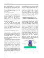
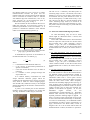
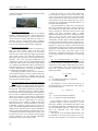
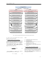
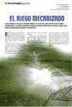
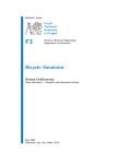
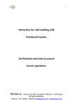
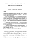
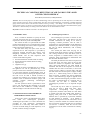
Science & Military 1/2012
TECHNICAL CONDITION DETECTION OF AIR TANKS IN THE ARMY
OF THE CZECH REPUBLIC
Jan FURCH, Josef GLOS, Ondřej RAZÝM
Abstract: The aim of the paper was to make a methodology used for performing the air tank inspections of combat and
special vehicles in the Army of the Czech Republic. The main asset of the methodology is introducing a suitable ultrasound
gauge which would be able to take measures without removing a coating. After taking a lot of measures and comparing
single gauges accuracy we came to a conclusion that the most convenient device is the DM 4 DL ultrasound thickness gauge.
This device is suitable namely for finding out the wall thickness of non-dismountable air tanks.
Keywords: Technical condition of air tanks. Air tank inspection.
1 INTRODUCTION
2.1 Technological procedure I
First, it would be desirable to specify the term
“air tank” and clarify the way of performing air tank
inspection in the Army of the Czech Republic.
The vehicle air tank is a special kind of a stable
pressure tank which serves as compressed air storage
used for controlling some motor vehicle equipment,
trailers and special equipment [1].
No later than every five years since the last
inspection the air tank inspection is provided by
inspecting certified personnel who observe “The
Obligatory Guideline, the evidence number TZ
1/2000 SOTD”. The air tank inspection itself
consists of the following tasks:
The technological procedure I consists of four
main parts. The first part is the shortest one and
includes information on taking an air tank by
inspecting certified personnel. The air tank is
supposed to be clean and labelled. On the label there
should be put a battalion number, a vehicle type and
the year of vehicle manufacture, and a military
number plate.
The second part deals with carrying out an
external check during which a coating is examined.
The coating should be clean and intact (with no
cracks, fragments or hammer-marks). Next, case
geometric shape requirements are determined with
the maximum deviation 2 mm.
The third part describes the interior inspection of
an air tank. First, the inner space of the air tank
should be cleaned of impurities and sediments.
Then, using and endoscope, the walls should be
examined. The aim of the inspection is to find out
whether there are cracks on the walls, or if an inner
coating is intact, if there is corrosion there, and what
the state of the most stressed spots is (edges, welding
joints, etc.). When having reason to believe that
there are cracks, a capillary test will be performed.
Also a colour defectoscopy might be applied which
is rather advanced technological procedure. If there
are cracks or disintegration of a material due to
corrosion, the air tank is examined with
Technological procedure II, or is disposed straight
away.
The fourth step to be taken is a pressure test.
First, the air tank is filled with water. Then,
overpressure
corresponding
with
operation
overpressure (nominal value stated on a tank label)
is created in the tank with a hand pump. Finally by
tapping weld joints with a little hammer (the
hammer mass is specified by a particular standard)
air tank tightness is checked.
If no leakage is
present, the overpressure will be increased to a test
value (1,5 times the amount of a nominal value) and
this overpressure is left in the tank till it is examined
(at least for 3 minutes). After the test has been
completed, we let the water out and the air tank dry
up. [2].
•
•
•
•
external examination and the check of coating,
internal inspection and the check of coating,
a pressure test,
a tightness test [1].
After the air tank is mounted back on a vehicle,
the tightness test will be performed only if the
pressure test has been satisfactory, and the aim of it
is to check the tightness of dismantleable joints. If
we have reason to believe during the inspection that
the wall of an air tank is thinner (because of
corrosion for example), we proceed to check wall
thickness with an ultrasonic thickness gauge and
calculate
strength
(following
Technological
Procedure II) [1].
Air tank operation check is performed at least
once a year and during this checking an air tank
label and air tank condition is visually examined,
and also sludge is removed from the air tank [1].
2 TECHNOLOGICAL PROCEDURES OF
PERFORMING INSPECTIONS
In the Army of the Czech Republic there have
been made two technological procedures.
Technological procedure I is a basic document for
providing air tank inspections. Technological
procedure II is used only when little cracks or
corrosion is found during air tank inspection, or an
air tank´s label is missing or illegible.
87
Science & Military 1/2012
The last step which is to be taken is renewing an
air tank coating, punching a test date, the next test
date and an inspecting certified personnel evidence
number on an air tank label (in case the test was
successful – no leakage, cracks, or permanent
deformities were found). Test results will be
recorded in the book of revisions of an air tank
revision station.
2.2 Technological procedure II
Technological procedure II is divided into six
parts. The first three parts are the same as in the
Technological procedure I. Te fourth part describes
the way of checking wall thickness with an
ultrasonic thickness gauge. The checking is
performed in the areas where corrosion was found
during inner examination, while observing relevant
standards (ČSN 015021 and ČSN 583-1,2,3). The
identified value of the smallest wall thickness is later
used during proof calculations.
The fifth part deals with a proof strength
calculation. The calculation follows the standard
ČSN 69 0010. Basic calculations are done for a
cylinder case and a torospherical bottom and they
are used for counting an allowed number of working
cycles and specifying the date of the next air tank
inspection. The sixth part of the Technological
procedure is the same as the fourth one of the
Technological procedure.
2.3 Inspection of non-dismountable air tanks
The previous two technological procedures
describe the inspections of air tanks which are
removed from a vehicle before the actual inspection.
However, in the Army of the Czech Republic there
are vehicles, the construction of which makes the
dismantling of air tanks impossible, or the
dismantling would be expensive and uneconomic.
So the air tank inspection of such vehicles is to be
tackled in a different way.
When inspecting these air tanks, we focus mainly
on careful external examination. In the air tanks with
an accessible cleaning valve it is desirable to
perform inner inspection with a fibroscope.
Following the inner inspection we check wall
thickness in corroded areas using an ultrasonic
thickness gauge. Before the check is carried out, it is
necessary to remove a coating in order to make the
measurement accurate. If the air tank is not
equipped with an accessible cleaning valve, which
means that it cannot be examined with a fibroscope,
other air tanks which have been already checked will
serve as the basis of determining its condition. After
the measurement with an ultrasonic thickness gauge
has been completed, braking system will be put into
operating state, and by increasing the overpressure to
the highest operating value (by a pressure gauge in a
88
driver´s cab), the tightness will be checked, and then
the measurement of critical places will be performed
again using the ultrasonic thickness gauge. Finally
the air tanks´ condition will be evaluated.
Air tanks cannot show signs of misuse,
deformation, ruptured welded joint, bumps, the
coating has to be compact. The inner part of an air
tank can be corroded on the surface. But there
cannot be point or inter-crystal corrosion there. The
air tanks have to be tight during the highest
operation overpressure, and when checking
thickness with an ultrasonic thickness gauge, it
cannot decrease by more than 5 percent.
3 METHODOLOGY PLAN TO FIND OUT
TECHNICAL CONDITION OF AIR TANKS
A methodology plan is based on original
technological procedures and the results of the
performed accuracy measuring of the ultrasonic
thickness gauge DM 4 DL. This gauge is considered
to be the most suitable. There is a dual probe in this
ultrasonic thickness device which means that a pulse
reflection measuring method is applied, see Fig. 1.
The device is compact and small sized having a
robust case. It is supplied by two AA alkaline
batteries providing up to 200 hrs of use. Dialog
probes resolution, V path error correction
(compensates for non-linearity of dual element
probes), zero point adjusting and ultrasonic flow
rectification are performed automatically by the
gauge. The measuring range is from 0,5 mm to 500
mm, the displayed resolution ranges from 0,01 mm
for the thickness of 99,99 mm, and 0,1 mm for the
thickness more than 99,99 mm. The period of
adjustable ultrasonic wave velocity ranges from
1000 ms-1 up to 9999 ms-1. The receiver bandwidth
is from 300 kHz to 10 MHz (amplification setting is
three-levelled – automatic, high and low). The
measurement update rate is 4 Hz, but it increases up
to 25 Hz in a minimum capture mode. [2].
Transmitter
Receiver
Filtering
Filtering
Piezo-changer
Piezo-changer
Partition
Case
Case
Underlying material
Fig. 1 Parts of a dual probe [6]
When measuring the thickness with the reflection
method Dual-Multi, the ultrasonic wave is sent into
Science & Military 1/2012
the material under test (gel is used as a contact
material/interface between the probe and the
material under test) and travels through the material
until it encounters an interface, that is a material
with different physical characteristics, such as air,
paint, corrosion, etc. At the interface the pulse is
reflected back to the probe, see Fig. 2.
We also measure the time needed for the wave to
make this round trip. If we know the velocity of
ultrasound proliferation in the environment c, it is
possible to calculate the thickness of the material
under test with the following equation (1).
The DA 451 is a commonly used dual probe. Its
measuring range is from 1,2 to 200 mm, and contact
diameter is 12,5 mm. The curvature of the surface to
be measured with the probe should be at least 15
mm. Probe frequency is 5 MHz and accuracy ± 0,05
mm. The DA 312 B16 is a special miniature probe
with a measuring range from 0,6 to 25 mm of 10
MHz frequency. Since the contact diameter is 3 mm,
the probe is used for measuring very small radii and
hole corrosion [4].
3.1 Plan of air tank methodological procedure
Probe Coating Test material c Corrosion layer s; t Fig. 2 The way of measuring thickness with the DM 4 DL
gauge applying the Dual-Multi method
A mathematical expression of the thickness of
the material under test is as follows [3]:
s=
c ⋅t
[m]
n
(1)
where:
s .....is the thickness of the material under test,
c ..... is the velocity of ultrasound proliferation in
specific environment,
t ...... is the time for the ultrasonic wave to make its
round trip,
n ..... is a number of wave passages through the
object under test.
In a common military environment are used
simple ultrasonic thickness gauges which are
calibrated to the ultrasound wave velocity typical for
steel, which is 5920 ms-1. More complex gauges,
such as DM 4 DL, enable the velocity to be changed
flexibly depending on the structure of the material to
be measured.
A probe is an essential part of each ultrasonic
thickness gauge. When measuring, two probes DA
451 (Fig. 3) and DA 312 B16 (Fig. 4) were used.
Fig. 3 Probe DA 451
Fig. 4 Probe DA 312 B16
Air tank demounting (only for the air tanks
which might be demounted from a vehicle) and
taking for inspection.
An air tank is demounted from a vehicle and then
taken for inspection. The air tank is to be free of dirt
and provided with a label containing a device
number, a type, the year of manufacture and a
vehicle evidence number. In case the air tank cannot
be demounted from a vehicle, the whole vehicle is
taken.
1) Air tank demounting (only for the air tanks
which might be demounted from a vehicle) and
taking for inspection.
An air tank is demounted from a vehicle and then
taken for inspection. The air tank is to be free of dirt
and provided with a label containing a device
number, a type, the year of manufacture and a
vehicle evidence number. In case the air tank cannot
be demounted from a vehicle, the whole vehicle is
taken.
2) Air tank preparation for inspection
All valves and other parts will be removed from
an air tank. If there is a label on the air tank which is
not fastened enough, non-hermetically welded, or
illegible, it will be replaced by a new one with the
information taken from a service place revision
book. The reason for removing the label is corrosion
under the label which occurs rather frequently,
because water and damp might get there (see Fig. 6).
Next, all holes will be sealed and a surface will be
cleaned depending on the amount of dirt. To clean it,
organic solvents, such as petrol for technical use,
paraffin oil and diesel are applied. As for nonflammable
organic
solvents,
we
use
perchlorethylene, trichloroethylene, etc. Regarding
alkaline water solutions, the cleaning agent of a
Synalod production marking might be applied. If
there is corrosion on the external side of an air tank,
it can be removed either mechanically or chemically.
To remove it mechanically, we use different brushes
and sandpapers. In order to remove it chemically, we
apply rust-removers like Rezol 2000, Loctite or
Pragokor 100. As to the air tanks which cannot be
dismounted from a vehicle, all the above operations
89
Science & Military 1/2012
will be performed the same way, but with an air tank
placed on a vehicle.
Fig. 5 Corrosion present under an air tank label
3) External air tank checking
The prime aim of external check is to examine
whether a coating stayed intact. The air tank cannot
show signs of hammer blows, cracks or breaches. If
we have reason to believe that there are cracks, it is
necessary to carry out the check using a capillary
test. The conditions of welding joints and deviations
from air tank geometric shape are also examined.
4) Internal air tank checking
When checking an internal tank, it is necessary to
have the inner surface clean and free from
impurities. If it is not, the surface is to be cleaned.
After this, the visual inspection might be performed
with a light viewer or an endoscope. Borescopes,
fiberscopes and videoscopes work on the endoscope
principle. The most up-to-date endoscopes are
videoscopes which consist of a probe equipped with
a miniature video camera. With software they enable
us to quantify spotted defects. When performing the
internal inspection, we concentrate on the presence
of cracks, deformations, corrosion, the condition of
bevelled spots and higher stress spots.
Following the actual results, relevant measures
will be taken. If there is reason to believe that there
are cracks or corrosion, a capillary test will be
performed and the spot will be checked with the DM
4 DL ultrasonic thickness gauge.
5) Air tank checking with an ultrasonic thickness
gauge
When checking air tanks with ultrasonic thickens
gauge, it is highly recommended that the DM 4 DL
is to be used. The biggest advantage of this gauge is
its ability to measure through an external coating.
The first step when using the gauge is the calibration
of it, but since a standard calibration is impossible to
make, all we can do is set the velocity of ultrasound
waves in the material. At present the only alternative
is to set the 5 920 ms-1 speed which is a speed for
steal. But not all air tanks are made of the same
material, therefore it would be advisable to develop
a database containing speeds used for single air
tanks. The database might be filled basically by two
different ways. The first one is to get the information
directly from the manufacturer, and the other one is
to take the measurements of disposed air tanks. The
air tanks will be cut in two and then, having gauge
precise calibration, we will calculate ultrasound
speed used later for measuring air tanks.
90
After the velocity is set, the areas which have
been selected in advance will be measured. The
areas will be chosen on the basis of internal check
results. Generally, the most exposed areas are those
at the bottom of an air tank, namely the ones close to
cleaning valves, welded joints and under labels, as it
has been mentioned before.
The measurement is taken after presetting the
function Dual-Multi (that means without removing
the coating) by moving slowly the probe DA 451
along a critical area. The device can be set for a few
modes. The most convenient mode is called
differential measurement where a nominal thickness
value is set by the user. Then, the areas which
approximate this value or are of smaller values are
searched for. Another option is the mode MIN which
is used to capture the thinnest value. Using this way,
the weakest areas of an air tank are found. They are
marked by inspecting certified personnel and the
measurement of these areas are taken with the DM 4
DL gauge in the THK mode. Each area is measured
three up to five times. The mean value of the
measuring is calculated and then the values as well
as the point location are recorded in a measuring
report.
As for non-dismountable air tanks, it is
determined that at the bottom part of an air tank the
area of an imaginary rectangular, the length of which
equals the air tank and the width equals one fifth of
an air tank diameter value, will be checked by the
DM 4 DL ultrasonic thickness gauge using the
following formula:
d=
D
[mm]
5
(2)
where:
d .... the width of an imaginary rectangular,
D.... an air tank diameter.
The thickness of an air tank wall must by no
means drop below a critical thickness value which is
determined as follows:
d crit = 0,95 ⋅ d nom
(3)
where:
d crit ...is critical air tank wall thickness,
d nom ..is nominal air tank wall thickness.
If the displayed value is not stabilized in the
± 0,02 mm range, it will be necessary to use the
probe DA 312 B16. Provided that the value is still
not stabilized, inspecting certified personnel switch
off the Dual-Multi function, remove the coating
from the examined area and perform the
measurement.
The record of the performed measurement will
be available in the service place and will serve as a
basis for next inspections. To calculate the strength
Science & Military 1/2012
Air tank inspection
Air tanks which can be dismounted from
a vehicle
Air tanks which cannot be dismounted
from a vehicle
Dismounting and taking for
Taking for inspection
Preparation for inspection
Preparation for inspection
External checking
External checking
Internal checking
Internal checking
Checking with an ultrasonic
thickness gauge
The DM 4 DL ultrasonic
thickness gauge
Instrument DM 4 DL
Instrument DM 4
Strength calculation
Strength calculation
Pressure test
Tightness test
Conclusion of the inspection
Conclusion of the inspection
Fig. 6 Diagram of suggested methodology for performing air tank inspection
we need to have the measured value of wall
thickness in the narrowest place.
6) Strength calculation of air tank thickness
To calculate the strength we need to have the
measured value of wall thickness in the narrowest
place. The calculation itself is done in compliance
with the standards ČSN 69 0010 – 4.5, 4.7 and 4.12.
To calculate the wall thickness (minimum
operational thickness) without added material we
apply the following equation [5]:
p⋅D
sR =
[mm].
2 ⋅ σD ⋅ ϕ − p
The minimum air tank wall
(operational thickness) is as follows [5]:
s ≥ sR + c [mm]
(4)
thickness
where:
sR ....wall thickness without added material,
p .....operating pressure,
D ....inside tank diameter,
φ .....longitudinal weld coefficient (0,5 to 0,8; for
torospheric bottom it is 1),
σD ...tolerable stress of a cylinder case,
c .....material added for corrosion and manufacturing
tolerance.
7) Pressure testing of demountable air tanks
The pressure testing of an air tank is the main
activity when performing air tank inspections. While
putting air tanks to test, the testing beds of pressure
tanks having different designs and parameters are
used. A more detailed description is available in the
Technological Procedure II.
(5)
91
Science & Military 1/2012
weld
cleaning valve
References
[1] Log 1-3. Odborný technický dozor v rezortu
Ministerstva obrany. Praha :
obrany, 2004.
connection joints
Ministerstvo
[2] User manual DM 4 DL. Krautkramer.
[3] ČSN EN 14127. Non-destructive testing Ultrasonic thickness measurement. Praha :
Český normalizační institut, 2011.
lower part
Fig. 7 The most corroded areas of an air tank
8) Tight testing of non-dismountable air tanks
A brake system including air tanks are put into
operating state (pressure). Then, the operation
overpressure of the braking system is checked using
a metrologically certified pressure gauge placed in a
driver´s cab. In case the pressure drops, the tightness
of joints, pipes and air tanks is checked. The system
tightness is verified with an ultrasound tightness
detector. If the testing turns out to be positive, the air
pressure will be decreased to the highest operation
overpressure and the tightness of all air tanks will be
checked. After ten minutes the tightness test is
repeated again. The condition will be recorded in the
documentation.
9) The end of inspection
When the inspection comes to an end, an air tank
will be dried, a coating will be renewed, a cleaning
valve will be screwed in and everything will be
recorded in the documentation. Besides keeping a
record in the book of revisions, a revision certificate
will be written out, relevant data will be punched in
an air tank label, or a new label will be attached. We
expect in our methodological procedure that when
the inspection comes to an end, ultrasound testing
result will be evaluated and finally recorded in an
information logistics system (compliance/rejection
of the pressure testing results; in case of rejection,
the graphical record of plot will be uploaded and
described).
4 CONCLUSION
The aim of the paper was to make a methodology
used for performing the air tank inspections of
combat and special vehicles in the Army of the
Czech Republic. The main asset of the methodology
is introducing a suitable ultrasound gauge which
would be able to take measures without removing a
coating. After taking a lot of measures and
comparing single gauges accuracy we came to a
conclusion that the most convenient device is the
DM 4 DL ultrasound thickness gauge. This device
is suitable namely for finding out the wall thickness
of non-dismountable air tanks.
92
[4] Testima. [online]. 2011 [cit. 2011-05-26].
Sondy. Available at: <http://www.testima.
eu/27,0~Sondy>.
[5] ČSN 69 0010 část 4.5. Stationary pressure
vessels. Technical rules. Design. Cylindrical
parts of vessels. Praha : Vydavatelství Úřadu
pro normalizaci a měření, 1990.
Acknowledgement
The work presented in this paper has been
supported by project PRO and specific research.
Assoc. Prof. Dipl. Eng. Jan FURCH, Ph.D.
University of Defence
Kounicova 65
612 00 Brno
Czech Republic
E-mail: [email protected]
Dipl. Eng. Josef GLOS
University of Defence
Kounicova 65
612 00 Brno
Czech Republic
E-mail: [email protected]
Dipl. Eng. Ondřej RAZÝM
Ministry of Defence
Dobrovodského 15
339 01 Klatovy
Czech Republic
E-mail: [email protected]