1
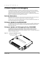
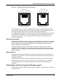
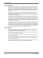
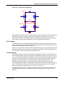
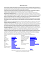
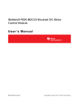
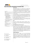
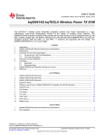
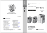
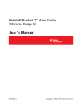
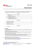
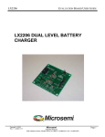
Stellaris® RDK-BDC24 Brushed DC Motor Control Module User ’s Manual RDK-BDC24 -UM-0 4 Co pyrigh t © 2 010– 201 2 Te xas In strumen ts Copyright Copyright © 2010–2012 Texas Instruments, Inc. All rights reserved. Stellaris and StellarisWare are registered trademarks of Texas Instruments. ARM and Thumb are registered trademarks, and Cortex is a trademark of ARM Limited. Other names and brands may be claimed as the property of others. Texas Instruments 108 Wild Basin, Suite 350 Austin, TX 78746 http://www.ti.com/stellaris 2 January 4, 2012 Stellaris® Brushed DC Motor Control User’s Manual Table of Contents Chapter 1: Stellaris® Brushed DC Motor Control Reference Design Kit (RDK) Overview ........................ 7 Feature Summary ............................................................................................................................................... 8 Specification Overview ....................................................................................................................................... 8 Reference Design Kit Contents .......................................................................................................................... 9 Chapter 2: Using the Reference Design Kit ................................................................................................. 11 Important Information........................................................................................................................................ 11 Developing with the RDK.................................................................................................................................. 11 Power Supply Selection .................................................................................................................................... 11 Motor Selection ................................................................................................................................................. 12 Chapter 3: Firmware Updates and Debugging............................................................................................. 13 General Information .......................................................................................................................................... 13 Firmware Update Using RS232/CAN ............................................................................................................... 13 Firmware Update and Debugging Using JTAG/SWD ....................................................................................... 13 Chapter 4: Hardware Description .................................................................................................................. 15 System Description ........................................................................................................................................... 15 Key Hardware Components.............................................................................................................................. 15 Schematic Description ...................................................................................................................................... 15 Microcontroller, CAN, and I/O Interfaces (Schematic page 1) ...................................................................... 15 Output Stage and Power Supplies (Schematic page 2)................................................................................ 17 Texas Instruments’ Featured Parts................................................................................................................... 20 Appendix A: Schematics................................................................................................................................ 21 Appendix B: Board Drawing .......................................................................................................................... 24 Appendix C: Bill of Materials (BOM) ............................................................................................................. 25 January 4, 2012 3 List of Figures Figure 1-1. Figure 1-2. Figure 3-1. Figure 3-2. Figure 4-1. Figure 4-2. Figure 4-3. Figure 4-4. Figure B-1. 4 MDL-BDC24 Brushed DC Motor Control Module ............................................................................ 7 MDL-BDC24 Module Key Features (top view) ................................................................................ 9 Locating the JTAG/SWD Connector.............................................................................................. 13 Firmware Debugging Using JTAG/SWD ....................................................................................... 14 MDL-BDC24 Circuit Board ............................................................................................................ 15 MDL-BDC24 JTAG/SWD Connector............................................................................................. 16 Network Connector Pin Assignments............................................................................................ 17 Synchronous Rectification............................................................................................................. 19 Component Placement Plot........................................................................................................... 24 January 4, 2012 Stellaris® Brushed DC Motor Control User’s Manual List of Tables Table 2-1. Mabuchi RS-555PH-3255 Motor Specifications ............................................................................ 12 Table 4-1. Detailed List of Texas Instruments’ Featured Parts ...................................................................... 20 Table C-1. RDK-BDC24 Bill of Materials (BOM) ............................................................................................. 25 January 4, 2012 5 6 January 4, 2012 C H A P T E R 1 Stellaris® Brushed DC Motor Control Reference Design Kit (RDK) Overview The RDK-BDC24 is a Stellaris reference design for speed control of 12 V and 24 V brushed DC motors at up to 40 A continuous current. Features include high-performance CAN and RS232 networking as well as a rich set of control options and sensor interfaces, such as analog and quadrature encoder interfaces. High-frequency PWM enables the DC motor to run smoothly and quietly over a wide speed range. The MDL-BDC24 uses highly optimized software and a powerful 32-bit Stellaris LM3S2616 microcontroller to implement open-loop speed control as well as closed-loop control of speed, position, or motor current. The Reference Design Kit (RDK-BDC24) contains an MDL-BDC24 motor control module as well as additional hardware and software for evaluating RS232 communication. After evaluating the RDK-BDC24, users may choose to either customize parts of the hardware and software design or use the MDL-BDC24 without modification. See the MDL-BDC24 board data sheet (available for download from http://www.ti.com/stellaris) for complete technical specifications. In addition, the MDL-BDC24 Getting Started Guide (GSG-MDL-BDC24) provides a step-by-step guide to wiring and using the module. Figure 1-1. January 4, 2012 MDL-BDC24 Brushed DC Motor Control Module 7 Stellaris® Brushed DC Motor Control Reference Design Kit (RDK) Overview Feature Summary The MDL-BDC24 control board provides the following features: Controls brushed 12 V and 24 V DC motors up to 40 A continuous Controller Area Network (CAN) interface at 1 Mbit/s Industry-standard servo (PWM) speed input interface RS232 to CAN bridge Limit switch, encoder, and analog inputs Fully enclosed module includes cooling fan Flexible configuration options with simple source file modification Easy to customize—full source code and design files available Specification Overview Key specifications of the MDL-BDC24 include: Quiet control of brushed DC motors – 15 kHz PWM frequency Three options for Speed control – Industry-standard R-C servo type (PWM) interface – Controller Area Network (CAN) interface – RS232 serial interface CAN communication – Multicast shared serial bus for connecting systems in electromagnetically noisy environments – 1M bits/s bit rate – CAN protocol version 2.0 A/B – Full configurability of module options – Real-time monitoring of current, voltage, speed, and other parameters – Firmware update RS232 serial communication – Bridges RS232 port to a CAN network – Directly interfaces to a PC serial port or National Instruments cRIO Status LED indicates Run, Direction, and Fault conditions Motor brake/coast selector Limit switch inputs for forward and reverse directions Quadrature encoder input (QEI) – Index input – 5 V supply output to encoder 8 January 4, 2012 Stellaris® Brushed DC Motor Control User’s Manual Analog input – Accepts 10 kΩ potentiometer or 0-3 V input Screw terminals for all power wiring Headers (0.1 inch pitch) for all control signals For detailed specifications including electrical parameters, see the MDL-BDC24 data sheet. Figure 1-2. MDL-BDC24 Module Key Features (top view) For power wiring use 12AWG Wire with # 6 ring or spade terminals Maintain 0.5 " clearance around all vents Motor output is not protected against short- circuits. From Power Distribution Module (– ) In Motor Out (– ) Motor (+) In (+) Motor Mounting holes 3.50 " centers User Switch Maintain 0.5" clearance around all vents CAN Port 6P6C CAN/RS232 Port Status LED Limit switch inputs Use hooks to prevent wires shaking loose Encoder Input Analog input (0-3V) Motor coast / brake jumper Reference Design Kit Contents The RDK-BDC24 contains everything needed to evaluate brushed DC motor control. The RDK-BDC24 includes: MDL-BDC24 motor control module – Suitable for motors up to 24 V 40 A – Uses a Stellaris LM3S2616 microcontroller Mabuchi RS-555PH-3255 Brushed DC Motor – 5000 RPM, 12 V, 3 A Universal input wall power supply – 12 V 1.25 A January 4, 2012 9 Stellaris® Brushed DC Motor Control Reference Design Kit (RDK) Overview – Plug adaptors for US, UK, EU, and AUST DB9S to 6P6C adapter – Connects the MDL-BDC24 to a PC RS232 port 6P-6C modular cable 7-ft – Use for RS232 or CAN connection CAN terminator – Plug-in 120-Ω terminator Adapter cable for ARM JTAG/SWD fine-pitch header – Texas Instruments Part ADA2 Reference design kit CD – Complete documentation, including Quickstart and user’s guides – LM Flash Programmer utility for firmware updates – Complete source code, schematics, and PCB Gerber files The source code can be modified and compiled using tools from Keil, IAR, CodeRed, CodeSourcery, GCC, and Code Composer Studio. 10 January 4, 2012 C H A P T E R 2 Using the Reference Design Kit This chapter provides information about using the RDK-BDC24. Important Information WARNING – In addition to safety risks, other factors that may damage the control hardware, the motor, and its load include improper configuration, wiring, or software. Minimize the risk of damage by following these guidelines. Always wear eye protection and use care when operating the motor. Read this guide before connecting motors other than the motor included in the RDK. DC motors may not be directly interchangeable and RDK parameter changes may be necessary before the new motor will operate correctly. Damage to the control board and motor can result from improper configuration, wiring, or software. Developing with the RDK The recommended steps for using the RDK are: Follow the README First document included on the kit CD. The README FIrst document will help you get the RS-555 motor up and running using the BDC-COMM Windows application in just minutes. It also contains important safety information that you should read before using the RDK. Use the BDC-COMM to evaluate and optimize target motor operation. Once the module is installed in the end application, use the BDC-COMM to configure and monitor motor operation. Using RS232, the BDC-COMM gives real-time access to a range of operating parameters. The MDL-BDC24 Getting Started Guide covers module setup and use in customer applications. Customize and integrate the software and/or hardware to suit an end application. This user’s manual and the RDK-BDC24 Firmware Development Package User’s Guide are two important references for completing hardware and software modifications. New software can be programmed in the MDL-BDC24 using either BDC-COMM, or using a JTAG/SWD debug interface. Power Supply Selection The MDL-BDC24 is designed primarily for use with 12 V or 24 V sealed lead-acid batteries. Other power sources may be used as long as the MDL-BDC24’s voltage range is not exceeded under any condition. There are two important considerations when selecting a power supply. The first is specifying a supply that can supply the starting current of the motor. Even unloaded motors may have a starting current that can momentarily exceed 60 A. Some switching power supplies will shut down very January 4, 2012 11 Using the Reference Design Kit quickly when starting a brushed DC motor. The power supply does not need to maintain regulation during start, but it must ensure that the supply voltage remains above the under-voltage limit. The second consideration is how the power supply handles back-EMF and regeneration currents. During rapid deceleration of loads with high inertia, the motor acts as a generator. This current is rectified by the MDL-BDC24 back into the bus capacitor. As the capacitor charges, the voltage at the supply terminals may increase. It is important that the power supply can handle this momentary condition without entering a fault condition. The power supply must also present sufficiently low impedance so that the MDL-BDC24’s voltage rating is not exceeded. A sealed lead acid battery easily meets these requirements. NOTE: The MDL-BDC24 does not have reverse polarity input protection. Motor Selection The MDL-BDC24 operates 12 V to 24 V brushed DC motors. Typical motors include model BI802-001A from CIM and model RS-555PH-3255 from Mabuchi (see Table 2-1 for motor specifications). Some very small DC motors or motors in lightly loaded applications may have a limited useful speed range when controlled with PWM based voltage controls. The MDL-BDC24 can also drive resistive loads with some de-rating to allow for increased ripple current inside the module. See the MDL-BDC24 board data sheet for full specifications. Table 2-1. Mabuchi RS-555PH-3255 Motor Specifications Parameter Value Units Speed 3953 RPM Current 1.244 A Power 7.139 W Torque 17.25 mMm Speed 2325 RPM Current 3.627 A Power 14 W Torque 57.5 mMm No load speed 4650 RPM No load current 0.223 A At maximum efficiency At maximum power General characteristics 12 January 4, 2012 C H A P T E R 3 Firmware Updates and Debugging The MDL-BDC24 supports two methods for updating the firmware resident in the LM3S2616 microcontroller. The primary method, commonly used for field updates, uses the CAN or RS232 interface and a Flash-resident boot loader for firmware transfer. During actual firmware development, direct access and debug capability is preferable. The MDL-BDC24 included in the RDK has a JTAG/SWD connector installed for this purpose. General Information StellarisWare firmware revisions are referenced using four-digit numbers that increase with new releases, but are not necessarily contiguous (that is, numbers may be skipped). The flash memory region between 0x0000 and 0x07FF contains a CAN/RS232 boot loader. The main firmware image should be loaded at 0x0800. Firmware Update Using RS232/CAN The MDL-BDC24 firmware can be updated over RS232 or CAN using the BDC-COMM utility and the cables included in the reference design kit. See the MDL-BDC24 Getting Started Guide for step-by-step instructions. Firmware Update and Debugging Using JTAG/SWD The MDL-BDC24 included in the RDK has a 2 x 5 fine-pitch header installed for firmware programming and debugging using JTAG/SWD. JTAG is a four-wire interface. SWD is a high-performance, two-wire interface with similar capabilities. Figure 3-1 on page 13 shows how to locate the JTAG/SWD connector. Figure 3-1. Locating the JTAG/SWD Connector JTAG /SWD Connector Pin 1 is at this end January 4, 2012 13 Firmware Updates and Debugging When using the JTAG/SWD cable, pay special attention to the location of pin 1 on the connector. When inserted correctly, the cable runs back across the bottom of the case, covering the rectangular inset. See Chapter 4, “Hardware Description,” for additional information on the JTAG/ SWD connector. Any Stellaris evaluation boards can be used as a low cost In-circuit Debug Interface (ICDI) for both programming and debugging. The ICDI circuit is compatible with LM Flash Programmer as well as leading development tools for ARM® Cortex™-M3. Evaluation versions for several tools are available from www.ti.com/stellaris. Figure 3-2. Firmware Debugging Using JTAG/SWD Ribbon cabl e ADA2 10-pin to 20-pin Adapter Cable PC running LMFlash Programmer or o ther De velop ment tool USB 14 Any Stell aris® Eva luation Board. No softwa re required. January 4, 2012 C H A P T E R 4 Hardware Description The MDL-BDC24 motor control module uses a highly integrated Stellaris LM3S2616 microcontroller to handle PWM synthesis, analog sensing, and the CAN/RS232 interface. Only a few additional ICs are necessary to complete the design. The entire circuit is built on a simple two-layer printed circuit board. All design files are provided on the RDK CD. System Description A unique aspect of the MDL-BDC24 design is the integrated CAN interface and low-cost, fan-cooled MOSFET array that handles high current in a small form-factor. The motor control consists of an H-bridge arrangement which is driven by fixed-frequency PWM signals. Key Hardware Components Figure 4-1 shows the MDL-BDC24 circuit board with the enclosure and cooling fan removed. Figure 4-1. MDL-BDC24 Circuit Board DC bus capacitor Current sense circuit MOSFET H- bridge JTAG/ SWD connector ( other side) Switching power supply Stellaris® LM3S 2616 Microcontroller RS232 transceiver User switch Servo/ PWM input optocoupler 16 MHz crystal Gate driver 6P6C CAN /RS232 connector Status LED CAN transceiver Schematic Description Microcontroller, CAN, and I/O Interfaces (Schematic page 1) Page 1 of the schematics shows the microcontroller, CAN port, RS232 port, and sensor interfaces in detail. January 4, 2012 15 Hardware Description Microcontroller At the core of the MDL-BDC24 is a Stellaris LM3S2616 microcontroller. The LM3S2616 contains a peripheral set that is optimized for networked control of motors, including 6 high-speed ADC channels, a motor control PWM block, a quadrature encoder input, as well as a CAN module. The microcontroller's PWM module can generate two complementary PWM signal pairs that are fed to the power stage. Complementary PWMs are important for synchronous rectification (see “Output Stage and Power Supplies (Schematic page 2)” on page 17). The LM3S2616 has an internal LDO voltage regulator that supplies 2.5 V power for internal use. This rail requires only three capacitors for decoupling and is not connected to any other circuits. Clocking for the LM3S2616 is facilitated by a 16 MHz crystal. Although the LM3S2616 can operate at up to 50 MHz, in order to minimize power consumption, the PLL is not enabled in this design. The 32-bit Cortex-M3 core has ample processing power to support all features including 1 Mbits/s CAN and RS232 with a clock speed of 16 MHz. Debugging The microcontroller supports JTAG and SWD debugging as well as SWO trace capabilities. To minimize the board area, the MDL-BDC24 uses a 0.050" pitch header footprint which matches ARM's fine-pitch definition (Figure 4-2). The connections are located on the bottom of the module, under the serial number label. The module included in the reference design kit has a header installed; however, the standard MDL-BDC24 (available as a separate item) does not have the header installed. Some in-circuit debuggers provide a matching connector. Other ARM debuggers can be used with the adapter board included in the RDK. Figure 4-2. MDL-BDC24 JTAG/SWD Connector 1 2 TMS/SWDIO TCK/SWCLK TDO TDI SRSTn +3.3V GND GND GND 9 10 Figure 4-2 shows the pin assignments for the JTAG/SWD connector as viewed from the bottom (connector) side of the circuit board. CAN Communication A key feature of the LM3S2616 microcontroller is its CAN module that enables highly reliable communications at up to 1 Mbits/s. The MDL-BDC24 control board uses a Texas Instruments SN65HVD1050D CAN transceiver (U2), additional ESD protection (D6), and connectors. The pin assignments for the 6P6C/6P4C connectors are defined in CAN in Automation (CiA DS102). Figure 4-3 shows the network connector pin assignments. 16 January 4, 2012 Stellaris® Brushed DC Motor Control User’s Manual Figure 4-3. Network Connector Pin Assignments CANH CANL V+ CANH CANL GND RXD V+ GND TXD 1 6 6P6C RS232/CAN Socket Viewed from Top (Tab down) 1 6 6P4C CAN Socket Viewed from Top (Tab down) The V+ signal (Pin 2) is not used in the MDL-BDC24, however, it is passed through to support other devices that either provide or use power from this terminal. The typical application for V+ is in providing a small amount of power to optocouplers for isolating CAN signals. For 1-Mbps CAN communication over distances up to 20 feet, the network should be terminated at each end with a 100Ω resistor. This value is slightly lower the normal 120Ω terminator, but it accelerates the bus’ return to the recessive state which is important in high-data rate, high node-count applications. RS232 Communication The MDL-BDC24 supports a full set of network control and configuration functions over a standard RS232C serial interface. The command protocol is essentially the same as the protocol used on the CAN interface, thereby allowing the MDL-BDC24 to automatically bridge all commands between the RS232 and CAN interfaces. A TRS3221E RS232 transceiver was selected to translate the CMOS logic levels from the LM3S2616's UART0 to RS232 levels. Its internal charge-pump generates positive and negative voltages from the +5 V supply pin. Integrated ESD protection means that no external protection device is necessary. Other Interfaces Interfaces for an encoder (or tachometer), limit switches, and brake control are provided on 0.1" pin headers. The connections to the microcontroller are ESD-protected and in most cases have 10 kΩ pull-up resistors. The brake and user switch inputs use the LM3S2616 microcontroller's internal pull-up resistor. The analog input has a 0 to 3 V span. In order to use a 10 kΩ potentiometer, a 1 kΩ “padding” resistor is provided on J4.1 to drop 300 mV from the 3.3 V rail when the potentiometer is connected. Output Stage and Power Supplies (Schematic page 2) Page 2 of the schematics details the power supplies, gate drivers, output transistors, sensing, and fan control circuits. January 4, 2012 17 Hardware Description Motor Output Stage The motor output stage consists of an H-bridge with High-/Low-side gate drivers. Each leg of the H-bridge has two paralleled MOSFETs. The MOSFETs are connected in parallel to reduce total Rds (on) to about 2.5 mΩ and to provide additional surface area for fan cooling. The fan blows directly on the TO-220 MOSFETs, which are arranged radially around the DC bus capacitor. A plastic ring encompasses the MOSFETs providing mechanical support and ensuring that the tabs do not touch. The gate driver provides high peak currents to rapidly switch the gates of the MOSFETs when directed by the microcontroller’s PWM module. An internal charge-pump allows the drivers to maintain MOSFET gate voltage, even under low-voltage conditions. Resistor R34 sets the gate drive dead-time to approximately 2μs. Because the high-side MOSFETs are N-Channel types, a positive Vgs is required to switch them on. The gate driver uses a simple boot-strapping technique to ensure that the high-side Vgs remains above the Vgs (on) threshold. Whenever the low-side MOSFETs are on, the associated boot-strap capacitor (C34 or C36) charges from the internal charge-pump regulator. Later, when the high-side MOSFETs turn on, the boot-strap capacitor maintains power to the high-side driver with respect to the Motor terminal. One restriction with the boot-strap capacitor method is that the capacitor voltage will decay to an unacceptable level unless a low-side MOSFET is periodically switched on. This state only occurs when the motor is running full-forward or full-reverse. The gate driver has an internal sense circuit the inserts small low-side pulses whenever the bootstrap voltage decays. The short duration has no measurable impact on motor speed. The boot-strap monitor capability is the reason that the gate driver controls dead-time rather than the LM3S2616 microcontroller. Switching Scheme To reduce power dissipation in the H-bridge, the MDL-BDC24 uses synchronous rectification. Synchronous rectification uses the complementary MOSFET, rather than a diode, to provide a low-resistance current path during the PWM off period. Figure 4-4 shows the current paths through a complete PWM_ON, Dead-time, PWM_OFF cycle. The motor is modelled primarily as an inductor. During the PWM_ON period, Q1 on the high-side and Q2 on the low-side provide a path that increases current in the motor. The 2μs DEAD_TIME period starts with Q1 turning OFF. Current continues to flow through the load, with the path being completed by the Q2 intrinsic diode and Q4. The voltage drop across Q2 is equal to a forward-biased diode. Next, the synchronous rectification period, PWM_OFF, occurs when Q2 is ON. The voltage drop across Q2 is now greatly reduced. The load current decays during this period. 18 January 4, 2012 Stellaris® Brushed DC Motor Control User’s Manual Figure 4-4. Synchronous Rectification +VM PWM_ON Q1g Q1 Q3 Q3g Motor PWM_OFF Q2g DEAD_TIME Q2 Q4 Q4g During PWM_OFF, assuming a 40 A load, Q2 losses are approximately 40W without synchronous rectification. This drops to just 4W if synchronous rectification is used (Rds-on = 2.5 mΩ). Synchronous rectification significantly improves drive-stage efficiency, particularly at lower duty cycles (50% and less) when the PWM_OFF time is longer that the PWM_ON time. Power Supply The MDL-BDC24 uses a TPS54040-based switching power supply for optimal efficiency over a wide operating range. Resistor R20 sets the switching frequency at around 700kHz, which allows the use of a small inductor and output capacitor. The 5-V rail is used for the cooling fan, CAN and RS232 transceivers, current sense amplifier, and quadrature encoder functions. A low drop-out voltage linear regulator (TPS73633) generates the 3.3-V rail which is used by the MCU and peripheral circuitry. Current Sensing The current sensing circuit consists of a high-side shunt resistor (R23) and a specialized current sense amplifier (INA193). Due to the high current capabilities of the bridge, the shunt resistor is just 1 mΩ. The INA193 amplifier has a fixed gain of 20 V/V which results in a signal into the ADC of 20 mV/A for a full-scale reading of 150 A. Because the sense resistor is in the high-side of the H-bridge, the current through it is only positive when the high-side MOSFETs are on. The MDL-BDC24 software takes this into consideration when sampling the current waveform. When operating smaller motors, or lightly-loaded large motors, the INA193 may be operating with a Vsense less than 20 mV. This region has reduced current sense amplifier accuracy. See the INA193 data sheet for full details on Low Vsense Case 1 and Case 3. The PCB design has an option to populate an INA282 current sense amplifier. This was done to evaluate a future build option. The INA282 and supporting components are omitted from the assembly. January 4, 2012 19 Hardware Description Voltage Sensing A simple divider resistor network (16 and R18) scales the Vbus rail down to the range of the ADC (0-3 V). The full-scale ADC measurement (ADC=1023) corresponds to a bus voltage of 36 V. Fan Control The cooling fan is self-contained and uses a small, 5 V brushless DC motor. The MDL-BDC24 supports On/Off software control of the fan using Q3. The fan operates when the motor is running or when the temperature exceeds a certain threshold. The LM3S2616 microcontroller has an internal temperature sensor and a simple software table correlates the microcontroller temperature to the overall system temperature. Texas Instruments’ Featured Parts The MDL-BDC24 features a range of semiconductors from Texas Instruments as shown in Table 4-1. Table 4-1. Detailed List of Texas Instruments’ Featured Parts Part Number Description Use Features LM3S2616 Stellaris® Microcontroller System control SN65HVD1050 High-Speed EMC Optimized CAN Transceiver CAN communications TRS3221E Single-Channel RS-232 Compatible Line Driver/Receiver RS232 communications • • • • • • • • • • • • TPS54040 0.5 A Step Down SWIFT™ Converter with Eco-Mode™ 5V Power Supply TPS73633 INA193 20 Cap-Free, NMOS, 400 mA LowHDropout Regulator with Reverse Current Protection 3.3V Power Supply Voltage Output High-Side Measurement Current Shunt Monitor Motor current measurement • • • • • • • • • • • • • • • • ARM® Cortex™-M3 core Motion control capabilities 64 KB Flash. High electromagnetic immunity (EMI) Very low electromagnetic emissions (EME) Bus-fault protection of -27 V to 40 V Dominant time-out function Power-up/down glitch-free bus inputs and outputs Operates up to 250 kbits/sec Low standby current... 1 µA Typ External Capacitors... 4 × 0.1 µF RS-232 bus-pin ESD protection exceeds ±15 kV using human-body model (HBM) 3.5 V to 42 V input voltage range 200-mΩ high-side MOSFET High efficiency at light loads with a pulse skipping Eco-Mode™ 100 kHz to 2.5 MHz switching frequency Stable with no output capacitor or any value or type of capacitor Input voltage range of 1.7 V to 5.5 V Ultra-low dropout voltage: 75 mV typ Excellent load transient response Low reverse leakage current Low noise: 30 ìVRMS typ (10 Hz to 100 kHz) 0.5% initial accuracy Wide common-mode voltage –16 V to +80 V Low error 3.0% over temp (max) Wide bandwidth: up to 500 kHz Low quiescent current 900 vvµA (max) Complete current sense solution January 4, 2012 A P P E N D I X A Schematics This section contains the schematic diagrams for the RDK-BDC24. MCU, Network, and Interface on page 22 Power Supplies and Output Stage on page 23 January 4, 2012 21 Schematic page 1 1 2 3 4 5 Status LED Calibrate/ID LED_GRN R1 100 SW1 U1 LED_RED R4 U0RX U0TX LED_GRN SPDIN CANRX CANTX K A2 Red 150 A U3 Green A1 SWITCH SW-B3S1000 6 D1 AHI ALO +3.3V 17 18 19 20 21 22 25 26 +3.3V PA0/U0RX PA1/U0TX PA2/PWM4 PA3/PWM5 PA4/CAN0Rx PA5/CAN0Tx PA6/PWM0 PA7/PWM1 PB0/PWM2 PB1/PWM3 PB2/I2C0SCL PB3/I2C0SDA PB4/C0PB5/C1PB6/C0+ PB7/NMI 41 42 47 27 58 57 56 55 BHI BLO C1 R3 1.0K +5V 6 1 5 2 4 3 0.1UF SPDIN GD_RESETn FAN_ON FAN_ON LIMIT2 LIMIT1 J1 R2 1 2 3 150 FEMALE-1X3 PWM Speed Input +3.3V J2 1 3 5 7 9 TCK/SWCLK TMS/SWDIO TDI TDO QE_A R5 10K TMS/SWDIO TCK/SWCLK TDO TDI RESETn 2 4 6 8 10 GD_FAULTn QE_B LED_RED CON-HDR-2X5-050 OMIT OSC0 OSC1 34 35 PD0/IDX0 PD1 PD2/ADC5 PD3/ADC4 PE0/ADC3 PE1/ADC2 PE2/ADC1 PE3/ADC0 PE4/FAULT0 +3.3V 61 62 63 64 6 5 2 1 8 QE_INDEX BOARD_ID BRAKE_EN D2 ISENSE_193 POT/ANA VSENSE SWITCH NC NC NC TP2 SPDIN TP3 TMS/SWDIO TP4 TCK/SWCLK TP5 TDO TP6 TDI TP7 FANN C2 C3 10PF 10PF 32 33 R7 10K RESETn C8 0.01UF FANN TP8 +3.3V C40 2 GSOT05C R6 0.1UF 1.0K J3 1 + 2 S 3 - VSENSE 45 46 48 HDR-1X3 10K Position Pot WAKE HIB 40 RST 10 13 24 29 36 39 44 53 60 4 RS232 Transceiver VDDA VDD33 VDD33 VDD33 VDD33 GND GND GND GND GND GND GND GND GND GNDA VBAT LDO VDD25 VDD25 VDD25 VDD25 3 12 28 43 59 C4 C5 C6 0.01UF 0.01UF 0.1UF C7 0.1UF 16 12 1 3 7 C14 C15 0.1UF 0.1UF 14 ROUT FORCEOFF FORCEON EN 2 V+ VGND TXD 8 RXD 6 5 4 3 2 1 5 C13 6 C2+ C2- CAN Transceiver 0.1UF U2 0.1UF CANTX CANRX 1 4 +5V 15 VCC 8 C16 2 TRSF3221E 0.1UF TXD RXD 6 5 4 3 2 1 VCC VREF SN65HVD1050D R11 10K C17 0.1UF D6 GSOT05C J5 1 2 Jumper Installed (default) HDR-1X2 Limit Switch #2 (Reverse) 1 +3.3V 2 R12 10K J7 GSOT05C LIMIT1 1 2 Jumper Installed (default) HDR-1X2 Limit Switch #1 (Forward) CAN Port RJ11-6P-VERT Date 0 Sept 9, 09 Internal Prototype TI AEC - Austin A Sept 11, 09 Pre-production. See Round-up for change list. A1 Sept 14, 09 Change to use conventional Isense resistors. 108 Wild Basin Rd. Suite 350 Austin, TX 78746 C D Sept 21, 09 Pre-production release. Designer: Oct 7, 09 Adjust Isense and SMPS circuit values. DAY, JAG, KAK Sept 9, 10 Added INA282 current sense circuit as a future build option. INA282 parts are omitted. Drawn by: Removed INA282 current sense option. Added Additional 10uF to 5V and 3.3V rail Approved: Sept 21, 11 Drawing Title: Page Title: DAY, JAG, KAK MCU, Network and Interface Size 3 4 Document Number: B * 2 D Black Jaguar Brushed DC Motor Control Date: 1 C D5 CAN/RS232 Port Revision B Description 3 5 PIN 6 PIN 5 PIN 4 PIN 3 PIN 2 PIN 1 GSOT05C LIMIT2 J8 7 6 +5V RS GND PIN 6 PIN 5 PIN 4 PIN 3 PIN 2 PIN 1 RJ11-6P-VERT CANH CANL + A B I - HDR-1X5 Encoder C11 1UF +3.3V 13 2 C12 4 C1+ C1- 1 2 3 4 5 1 10 INVALID J4 D4 C9 C10 0.01UF 0.1UF J6 RIN 2 7 9 23 38 54 2 +5V 0.1UF R10 10K QE_A QE_B QE_INDEX LM3S2616 DOUT R9 10K GSOT05C 37 1 9 U0RX DIN C39 1 R8 10K 3 11 U0TX B +5V D3 +5V U4 D Brake (default) +3.3V +3.3V C Coast HDR-1X3 Brake/Coast Jumper 1 R24 1.0K OMIT JP1 1 2 3 POT/ANA XOSC0 XOSC1 +3.3V 16.00MHz Factory Test TP1 PC0/TCK/SWCLK PC1/TMS/SWDIO PC2/TDI PC3/TDO/SWO PC4/PhA0 PC5/C0o PC6/PhB0 PC7/C1+/C1o 30 31 Y1 B 52 51 50 49 11 14 15 16 A H11L1M BRAKE_EN Debug S + - 5 Rev * 9/21/2011 D Sheet 1 6 of 2 Schematic page 2 1 2 3 4 5 6 C18 1 2 BOOT VIN PH COMP 10 8 1 T2 4 5 R17 82K C29 (Blk) 0.01UF R20 162K EN SS/TR RT/CLK GND 35V C23 1.0UF 50V PwPd 3 C22 1.0UF 50V VSNS PwRGD C25 C26 0.01UF 7 6 R15 10K D7 SS16 10PF R19 1.87K 9 V- C21 1800uF R14 82K 11 + IN +3.3V 5 OUT 47uH R13 390K (Red) U6 TPS73633DBV +5V 3 C24 10UF 16v EN C19 1UF C38 10UF 16v GND +VBAT T1 A L1 SLF7045T-470MR90-H 0.1UF U5 TPS54040 4 NR A C20 1UF 2 12-24V POWER IN V+ C30 10UF 16v C27 0.01UF PWRGD TP9 +5V +5V_SHUNT FB1 1K ohm @ 100 MHz C35 0.1UF 5 +VBAT + GND V+ 3 R23 0.001 4 - 2 B 1 OUT ISENSE_193 U7 INA193AID B +VM Q2 2 1 3 R21 27 1 R22 27 3 Q1 2 +VM +VM C41 0.1UF OMIT Motor + MOTOR+ ALO +3.3V BHI R28 10K BLO 18 17 24 1 GD_FAULTn CB GHB SB GLB BHI BLO FAULT RESET CP1 CP2 RDEAD AGND GND GND GND 2 2 1 3 R27 27 C42 0.1UF OMIT C Cooling Fan Control 1 2 FANN C36 1UF +VM 1 FAN_ON Q6 14 13 2 15 16 C37 1UF Q7 1 R29 27 1 R30 27 MOLEX 35362 5V Fan Q3 FDV301N Motor T4 Z2 Q9 2 1 3 R32 27 1 R33 27 3 Q8 2 A4940 (Green) Drawing Title: VC080530A650DP Page Title: Power Supplies and Output Stage Document Number: B Date: 3 D Black Jaguar Brushed DC Motor Control C44 0.1UF OMIT Size 2 Red Black C43 0.1UF OMIT MOTOR- D 1 J9 +5V 25 23 22 R34 82.0K PAD GD_RESETn 6 5 4 3 R26 27 3 CA GHA SA GLA AHI 8 9 10 11 C34 1UF 2 19 12 C28 0.01UF 2 ALO 20 VBB (White) R18 1.0K VC080530A650DP 3 AHI VDD VREG 3 21 7 Q5 1 3 10UF 16v Q4 U8 0.1UF C33 C +VBAT C32 0.1UF 2 +3.3V VSENSE T3 Z1 C31 R16 11.0K 4 5 Rev D * 10/14/2011 Sheet 2 6 of 2 A P P E N D I X B Board Drawing This appendix shows the component placement plot for top (Figure B-1) Figure B-1. Component Placement Plot January 4, 2012 24 A P P E N D I X C Bill of Materials (BOM) Table C-1 provides the BOM for the RDK-BDC24. Table C-1. RDK-BDC24 Bill of Materials (BOM) Texas Instruments Part Number BD-BDC24 Final Assembly BOM (PCB Assembly + Enclosure) Bill Of Materials Created Item Ref 1 C1, C6, C7, C10, C12, C13, C14, C15, C16, C17, C18, C31, C32, C39, C40 2 C11, C19, C20, C34, C36, C37 9/21/2011 Description Mfg Part Number 15 Capacitor, 0.1uF 50V, 20% 0805 X7R Kemet C0805C104M5RACTU 6 Capacitor, 1.0uF 25V 10% X5R 0805 Taiyo Yuden TMK212BJ105KG-T 3 C2, C3, C25 3 Capacitor 10pF 50V 5% 0805 COG Kemet C0805C100J5GACTU 4 C21 1 Panasonic EEU-FC1V182S 5 C22, C23 2 Capacitor, 1800uF 35V 20% 18mmx20mm Capacitor, 2.2uF 50V 10% X7R 1210 Kemet C1210C225K5RACTU 6 C24, C30, C33, C38 C35 4 Capacitor, 10uF 16V 10% X7R 1210 Murata GRM32DR71C106KA01L 1 Capacitor, 0.1uF 50V, 20% 0603 X7R TDK C1608X7R1H104M Kemet C0603C104M5RACTU 7 8 9 C4, C5, C8, C9, C26, C27, C28, C29 D1 8 Capacitor, 0.01uF 50V, 5% 0805 X7R Kemet C0805C103J5RACTU 1 LED, Green, Red, 5mm T-hole, dual Kingbright Corp WP59SRSGW/CC 10 D1b 1 SPACER, PCB-LED T1-3/4, 109Mil Keystone 8902 11 D2, D3, D4, D5, D6 5 Diode, 2 Line 5V ESD Suppressor SOT23 Vishay GSOT05C-GS08 D7 1 Diode, Schottky, 60V, 1A ON Semiconductor Vishay SM05T1G 12 13 FB1 1 Ferrite Bead, 400mA, 1K Ohm@100Mhz Murata BLM18AG102SN1D 14 J1 1 Header, 1x3, 0.100, T-Hole, Vertical, Female 4UCON 00523 Sullins PPTC031LFBN-RC 15 J3, JP1 2 Header, 1x3, 0.100, T-Hole, Vertical Unshrouded, 0.230 Mate 4UCON 00798 FCI 68001-103HLF 4UCON 00806 FCI 68000-105HLF FCI 67997-104HLF 4UCON 00998 FCI 90512-001LF 16 January 4, 2012 Qty RDK-BDC24 Rev D J4 1 Header, 1x5, 0.100, T-Hole, Vertical Unshrouded, 0.230 Mate SS16-E3/61T 17 J5, J7 (Combined) 1 Header, 2x2, 0.100, T-Hole, Vertical Unshrouded, 0.230 Mate 18 J6 1 Connector, RJ11 Mod-Jack 6-6 Vert Flange Blk 4UCON 04912 19 J8 1 Connector, RJ11 Mod-Jack 6-4 Vert Flange Blk FCI 90512-003LF 4UCON 04911 20 J9 1 Molex 35362-0250 TDK SLF7045T-470MR90-H 21 L1 1 22 PCB 1 1 Header, 1x2 Surelock 2mm, Thole Vertical, shrouded Inductor 47uH, SMD 7mmx7mm, 0.9A, 0.18Ohm PCB, RDK, DD, BlackJag Rev D 23 Q1, Q2, Q4, Q5, Q6, Q7, Q8, Q9 8 MOSFET N-CH, TO-220 40V/60V 80A Anyone RDK-BLKJAG-D International Rectifier IRFB3206PBF Fairchild FDP038AN06A0 Fairchild FDP050AN06A0 25 Table C-1. RDK-BDC24 Bill of Materials (BOM) (continued) Texas Instruments Part Number BD-BDC24 Final Assembly BOM (PCB Assembly + Enclosure) Bill Of Materials Created 9/21/2011 Item Ref Qty RDK-BDC24 Rev D Description Mfg Part Number Fairchild FDV301N 24 Q3 1 MOSFET, N-CH, SOT-23, 25V, 220mA 25 R1 1 Resistor, 100 OHM 1/8W 5% 0805 Thick Panasonic ERJ-6GEYJ101V 26 R13 1 CRCW0805390KFKEA 27 R14, R17 2 Resistor, 390K Ohm, 1/8W, 1% 0805 Vishay Thick Resistor, 82K OHM 1/8W 5% 0805 Thick Panasonic 28 R16 1 ERJ-6ENF1102V 29 R19 1 30 R2, R4 2 Resistor, 11K Ohm, 1/8W, 1% 0805 Panasonic Thick Resistor, 1.87K Ohm, 1/8W, 1% 0805 Yageo Thick Resistor, 150 OHM 1/8W 5% 0805 Thick Panasonic 31 R20 1 32 8 33 R21, R22, R26, R27, R29, R30, R32, R33 R23 34 R3, R6, R18 3 35 R34 1 36 9 37 R5, R7, R8, R9, R10, R11, R12, R15, R28 SW1 1 Switch, Tact 6mm SMT, 160gf 38 T1 1 39 T2 1 40 T3 1 41 T4 1 42 U1 1 Terminal, Screw Vertical 15A Red Screw non captive Terminal, Screw Vertical 15A Black Screw - non captive Terminal, Screw Vertical 15A White Screw - non captive Terminal, Screw Vertical 15A Green Screw - non captive IC, Optocoupler Schmitt Trigger SMD-6 43 U2 1 CAN Transceiver 8-SOIC 44 U3 1 45 U4 1 1 46 U5 1 47 U6 1 48 U7 1 49 U8 1 50 Y1 1 51 Z1, Z2 2 Resistor, 162K Ohm, 1/8W, 1% 0805 Thick Resistor, 27 OHM 1/8W 5% 0805 Thick ERJ-6GEYJ823V RC0805FR-071K87L ERJ-6GEYJ151V Rohm MCR10EZPF1623 Panasonic ERJ-6GEYJ270V Resistor, 0.001 OHM, 4W 1% 2725 SMD Stackpole Electronics Resistor, 1K Ohm, 1/8W, 1% 0805 Panasonic Thick Resistor, 47K OHM 1/8W 5% 0805 Thick Rohm CSS2725FT1L00 Resistor, 10K Ohm, 1/8W, 1% 0805 Thick ERJ-6ENF1002V Panasonic Omron MCR10EZPJ473 B3S-1000 - Keystone 8191-2 Keystone 8191-3 Keystone 8191-4 Keystone 8191-6 Fairchild H11L1SR2M Fairchild H11L1SR2VM Texas Instruments Stellaris, LM3S2616-IQR50-A0 Texas Instruments RS232, Line Driver, 3V to 5.5V, Single Texas Channel, TSSOP 16 Instruments Texas Instruments Texas Regulator, SWIFT, Step Down, 0.5A, Instruments 42V, MSOP10 Regulator, Linear, 3.3V, SOT23-5 (DBV) Texas Instruments Texas Current Shunt Monitor, INA193, 20V/V Instruments Gain, 5SOT-23 Full Bridge MOSFET Driver, Allegro, 24- Allegro eTSSOP Crystal, 16.00MHz 5.0x3.2mm SMT NDK TVS Varistor, 30V, 30A, Transguard ERJ-6ENF1001V SN65HVD1050D LM3S2616-IQR50-A0 TRS3221ECPWR MAX3221ECPW TPS54040DGQ TPS73633DBV INA193AIDBVR A4940KLPTR-T Abracon NX5032GA16.000000MHZ ABM3-16.000MHZ-B2-T AVX VC080530A650DP Final Assembly Bill Of Materials 26 January 4, 2012 Stellaris® Brushed DC Motor Control User’s Manual Table C-1. RDK-BDC24 Bill of Materials (BOM) (continued) Texas Instruments Part Number BD-BDC24 Final Assembly BOM (PCB Assembly + Enclosure) Bill Of Materials Created 9/21/2011 Item Ref Part Number 52 Description Mfg 3 Jumper, 0.100, Gold, Black, Closed Sullins SPC02SYAN 53 1 Fan Assembly, 40x40x10mm, 5V, 5.3CFM, 2" Lead w/ Molex Sherlock connector SUNON KDE0504PFV2 ebmpapst 405 FH 54 1 Enclosure, ABS plastic 3 pieces Cypress LM-608-01 55 1 Label, with Model/Serial/Firmware info Anyone BJAG-LABELS 56 4 McMaster 90380A108 57 4 Screw, #4 x 0.375" plastite (for enclosure ) Screw, #4 x 0.625" Pan Head, Sheet Metal, Phillips/Slotted (for fan ) McMaster 90077A112 58 1 January 4, 2012 JP1b, J5b, J7b Qty RDK-BDC24 Rev D BOM, PCB, Black Jaguar, Rev D 27 IMPORTANT NOTICE Texas Instruments Incorporated and its subsidiaries (TI) reserve the right to make corrections, modifications, enhancements, improvements, and other changes to its products and services at any time and to discontinue any product or service without notice. Customers should obtain the latest relevant information before placing orders and should verify that such information is current and complete. All products are sold subject to TI’s terms and conditions of sale supplied at the time of order acknowledgment. TI warrants performance of its hardware products to the specifications applicable at the time of sale in accordance with TI’s standard warranty. Testing and other quality control techniques are used to the extent TI deems necessary to support this warranty. Except where mandated by government requirements, testing of all parameters of each product is not necessarily performed. TI assumes no liability for applications assistance or customer product design. Customers are responsible for their products and applications using TI components. To minimize the risks associated with customer products and applications, customers should provide adequate design and operating safeguards. TI does not warrant or represent that any license, either express or implied, is granted under any TI patent right, copyright, mask work right, or other TI intellectual property right relating to any combination, machine, or process in which TI products or services are used. Information published by TI regarding third-party products or services does not constitute a license from TI to use such products or services or a warranty or endorsement thereof. Use of such information may require a license from a third party under the patents or other intellectual property of the third party, or a license from TI under the patents or other intellectual property of TI. Reproduction of TI information in TI data books or data sheets is permissible only if reproduction is without alteration and is accompanied by all associated warranties, conditions, limitations, and notices. Reproduction of this information with alteration is an unfair and deceptive business practice. TI is not responsible or liable for such altered documentation. Information of third parties may be subject to additional restrictions. Resale of TI products or services with statements different from or beyond the parameters stated by TI for that product or service voids all express and any implied warranties for the associated TI product or service and is an unfair and deceptive business practice. TI is not responsible or liable for any such statements. TI products are not authorized for use in safety-critical applications (such as life support) where a failure of the TI product would reasonably be expected to cause severe personal injury or death, unless officers of the parties have executed an agreement specifically governing such use. Buyers represent that they have all necessary expertise in the safety and regulatory ramifications of their applications, and acknowledge and agree that they are solely responsible for all legal, regulatory and safety-related requirements concerning their products and any use of TI products in such safety-critical applications, notwithstanding any applications-related information or support that may be provided by TI. Further, Buyers must fully indemnify TI and its representatives against any damages arising out of the use of TI products in such safety-critical applications. TI products are neither designed nor intended for use in military/aerospace applications or environments unless the TI products are specifically designated by TI as military-grade or "enhanced plastic." Only products designated by TI as military-grade meet military specifications. Buyers acknowledge and agree that any such use of TI products which TI has not designated as military-grade is solely at the Buyer's risk, and that they are solely responsible for compliance with all legal and regulatory requirements in connection with such use. TI products are neither designed nor intended for use in automotive applications or environments unless the specific TI products are designated by TI as compliant with ISO/TS 16949 requirements. Buyers acknowledge and agree that, if they use any non-designated products in automotive applications, TI will not be responsible for any failure to meet such requirements. Following are URLs where you can obtain information on other Texas Instruments products and application solutions: Products Applications Audio www.ti.com/audio Automotive and Transportation www.ti.com/automotive Amplifiers amplifier.ti.com Communications and Telecom www.ti.com/communications Data Converters dataconverter.ti.com Computers and Peripherals www.ti.com/computers DLP® Products www.dlp.com Consumer Electronics www.ti.com/consumer-apps DSP dsp.ti.com Energy and Lighting www.ti.com/energy Clocks and Timers www.ti.com/clocks Industrial www.ti.com/industrial Interface interface.ti.com Medical www.ti.com/medical Logic logic.ti.com Security www.ti.com/security Power Mgmt power.ti.com Space, Avionics and Defense www.ti.com/space-avionics-defense Microcontrollers microcontroller.ti.com Video and Imaging www.ti.com/video RFID www.ti-rfid.com OMAP Mobile Processors www.ti.com/omap Wireless Connectivity www.ti.com/wirelessconnectivity TI E2E Community Home Page e2e.ti.com Mailing Address: Texas Instruments, Post Office Box 655303, Dallas, Texas 75265 Copyright © 2012, Texas Instruments Incorporated