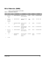
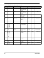
1
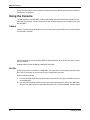
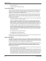
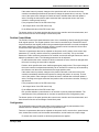
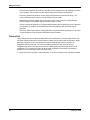
Stellaris® Brushed DC Motor Control Reference Design Kit User ’s Manual RDK-BDC-05 Co pyrigh t © 2 008– 201 0 Te xas In strumen ts Copyright Copyright © 2008–2010 Texas Instruments, Inc. All rights reserved. Stellaris and StellarisWare are registered trademarks of Texas Instruments. ARM and Thumb are registered trademarks, and Cortex is a trademark of ARM Limited. Other names and brands may be claimed as the property of others. Texas Instruments 108 Wild Basin, Suite 350 Austin, TX 78746 http://www.ti.com/stellaris 2 January 6, 2010 Microcontroller, CAN, and I/O Interfaces (Page 1) ....................................................................................... 35 Output Stage and Power Supplies (Page 2) ................................................................................................. 37 Chapter 6: Troubleshooting........................................................................................................................... 39 Appendix A: Schematics................................................................................................................................ 41 Appendix B: Board Drawing .......................................................................................................................... 45 Appendix C: Bill of Materials (BOM) ............................................................................................................. 47 4 January 6, 2010 Stellaris® Brushed DC Motor Control User’s Manual List of Figures Figure 1-1. Figure 1-2. Figure 2-1. Figure 2-2. Figure 2-3. Figure 2-4. Figure 2-5. Figure 3-1. Figure 4-1. Figure 4-2. Brushed DC Motor Control Module ................................................................................................. 9 MDL-BDC Module Key Features (top view) .................................................................................. 11 MDL-BDC's Servo PWM Input Stage ............................................................................................ 16 Basic wiring with a Servo-style speed command for open-loop motor control .............................. 18 Wiring diagram showing CAN-based control for closed-loop motor control .................................. 19 MDL-BDC Mechanical Drawing..................................................................................................... 20 MDL-BDC Default Jumper Settings............................................................................................... 21 BDC CAN Console ........................................................................................................................ 23 Diagram showing the two-step firmware update process.............................................................. 29 LM Flash Programmer Configuration ........ January 6, 2010 5 6 January 6, 2010 8 January 6, 2010 C H A P T E R 1 Stellaris® Brushed DC Motor Control Reference Design Kit (RDK) Overview The RDK-BDC is a Stellaris reference design for the MDL-BDC, a Controller Area Network (CAN) based DC motor control. The MDL-BDC motor control module provides variable speed control for 12 V brushed DC motors at up to 40 A continuous current. Features include high-performance CAN networking as well as a rich set of control options and sensor interfaces, including analog and quadrature encoder interfaces. High-frequency PWM enables the DC motor to run smoothly and quietly over a wide speed range. MDL-BDC uses highly optimized software and a powerful 32-bit Stellaris LM3S2616 microcontroller to implement open-loop speed control as well as closed-loop control of speed, position, or motor current. The Reference Design Kit (RDK-BDC) contains an MDL-BDC motor control module as well as additional hardware and software for evaluating CAN communication. After evaluating the RDK-BDC, users may choose to either customize parts of the hardware and software design or use the MDL-BDC without modification. See the MDL-BDC board data sheet (available for download from www.ti.com/stellaris) for complete technical specifications. Figure 1-1. January 6, 2010 Brushed DC Motor Control Module 9 Stellaris® Brushed DC Motor Control Reference Design Kit (RDK) Overview Feature Summary The MDL-BDC control board provides the following features: Controls brushed 12 V DC motors up to 40 A continuous Controller Area Network (CAN) interface at 1 Mbit/s Industry standard servo (pulse-width modulation (PWM)) speed input interface Limit switch, encoder, and analog inputs Fully enclosed module includes fan cooling Flexible configuration options Easy to customize—full source code and design files available Factory source code compiles to less than 16 KB Specification Overview Key specifications of the MDL-BDC include: Quiet control of brushed DC motors – 15 kHz PWM frequency Two options for Speed control – Industry standard R-C servo type (PWM) interface – Controller Area Network (CAN) interface CAN communication – Multicast shared serial bus for connecting systems in electromagnetically noisy environments – 1 Mbits/s bit rate – CAN protocol version 2.0 A/B – Full configurability of module options – Real-time monitoring of current, voltage, speed, and other parameters Status LED indicates Run, Direction, and Fault conditions Motor brake/coast selector Limit switch inputs for forward and reverse directions Quadrature encoder input – Index input – 5 V supply output to encoder Analog input – Accepts 10kΩ potentiometer or 0-3 V input Screw terminals for all power wiring Headers (0.1 inch pitch) for all control signals For detailed specifications including electrical parameters, see the MDL-BDC data sheet. 10 January 6, 2010 Stellaris® Brushed DC Motor Control User’s Manual Figure 1-2. MDL-BDC Module Key Features (top view) Motor terminals Reference Design Kit Contents The RDK-BDC contains everything needed to evaluate 12 V brushed DC motor control. The RDK-BDC includes: MDL-BDC motor control module – Suitable for motors up to 12 V 40 A – Uses a Stellaris LM3S2616 microcontroller Mabuchi RS-555PH-3255 Brushed DC Motor – 5000 RPM, 12 V, 3 A Universal input wall power supply – 12 V 1.25 A – Plug adaptors for US, UK, EU, and AUST. BDC CAN console – Convenient tool for controlling key MDL-BDC functions – Integrated graphics display and navigation switches – Firmware update feature – Based on EK-LM3S2965 Evaluation Kit January 6, 2010 11 Stellaris® Brushed DC Motor Control Reference Design Kit (RDK) Overview CAN cable – Connects the console to the MDL-BDC CAN terminator – Plug-in 120-Ω terminator USB cable – Provides power and communication to the BDC CAN console Adapter cable for ARM JTAG/SWD fine-pitch header – Texas Instruments Part ADA2 Ribbon cable for ARM JTAG/SWD – 20-position cable for using the BDC CAN console as a debug interface Reference design kit CD – Complete documentation, including Quickstart and user’s guides – LM Flash Programmer utility for firmware updates – Complete source code, schematics, and PCB Gerber files The source code can be modified and compiled using any of the following tools: 12 Keil™ RealView® Microcontroller Development Kit (MDK-ARM) IAR Embedded Workbench Code Sourcery GCC development tools Code Red Technologies development tools Texas Instruments’ Code Composer Studio™ IDE January 6, 2010 Using the Reference Design Kit rectified by the MDL-BDC back into the bus capacitor. As the capacitor charges, the voltage at the supply terminals may increase. It is important that the power supply can handle this momentary condition without entering a fault condition. The power supply must also present sufficiently low impedance so that the MDL-BDC’s voltage rating is not exceeded. A sealed lead acid battery easily meets these requirements. NOTE: The MDL-BDC does not have reverse polarity input protection. Motor Selection The MDL-BDC operates 12 V brushed DC motors. Typical motors include model BI802-001A from CIM and model RS-555PH-3255 from Mabuchi (see Table 2-1 for motor specifications). Some 14 January 6, 2010 Using the Reference Design Kit To reset the servo-style PWM input to the default factory range: 1. Disconnect the power to the MDL-BDC. 2. Hold down the USER switch with a straightened paperclip. 3. Reconnect power to the MDL-BDC 4. After 5 seconds, the LED flashes Red and Green slowly to indicate a successful calibration reset to factory settings. 5. Release the USER switch. Electrical Interface The servo PWM input is electrically isolated from other circuits using an optocoupler. The MDL-BDC board data sheet contains electrical specifications, including common-mode voltage limits, for the input stage. Figure 2-1. MDL-BDC's Servo PWM Input Stage The on-board resistor (R5) has been selected to allow a signal of only a few volts to drive the optocoupler. At 3.3 V or more it is advisable to add additional series resistance to limit the current into the LED. The PWM input stage is essentially a current-driven device, so the threshold for a logic high-level input is defined in milliamps. Some recommended values for an external resistor are listed in Table 2-3 CAN Communication 16 January 6, 2010 Stellaris® Brushed DC Motor Control User’s Manual USER switch on the MDL-BDC informs that particular module to accept the previously specified code. The CAN protocol used by the MDL-BDC includes the following capabilities: Firmware update over CAN Read supply voltage, motor voltage, temperature, and current Set motor voltage or target position Set control mode to speed or position Configure parameters Enable features such as closed-loop speed and position control. The CAN protocol provides a number of commands and divides them into groups based on the type of command. The commands are grouped according to broadcast messages, system level commands, motor control commands, configuration commands, and motor control status information. The interface also provides a method to extend the network protocol to other devices by defining a CAN device encoding that takes into account device type and manufacturer. See the RDK-BDC Software User's Guide for complete details. The RDK-BDC includes a CAN board with an example application that demonstrates CAN control. Default Parameters January 6, 2010 17 Stellaris® Brushed DC Motor Control User’s Manual Figure 2-3 shows an advanced wiring configuration using the CAN interface. Wiring for position sensing using both a position potentiometer and a quadrature encoder is detailed. Although two sensor types are shown, the MDL-BDC software supports control and monitoring of only one sensor at a time. Figure 2-3. Wiring diagram showing CAN-based control for closed-loop motor control January 6, 2010 19 Using the Reference Design Kit Mechanical Drawing Figure 2-4 shows the MDL-BDC’s physical dimensions. The module has two 0.175" (4.5 mm) diameter mounting holes as indicated. Figure 2-4. MDL-BDC Mechanical Drawing Important: The MDL-BDC should be mounted so that the vents in the top and sides of the module are not restricted in any way. A clearance of ½ inch should be maintained around the module to aid cooling. Status LED Table 2-5 lists all LED status and fault codes. Fault information is prioritized, so only the highest priority fault will be indicated. Table 2-5. Normal Operating Conditions LED State Module Status Normal Operating Conditions 20 Solid Yellow Neutral (speed set to 0) Fast Flashing Green Forward Fast Flashing Red Reverse January 6, 2010 Stellaris® Brushed DC Motor Control User’s Manual Solid Green Full-speed forward Solid Red Full-speed reverse Fault Conditions Slow Flashing Yellow Loss of CAN or servo link Slow Flashing Red Fault Calibration or CAN Conditions Flashing Red and Green Calibration mode active Flashing Red and Yellow Calibration mode failure Jumper Settings Figure 2-5 shows the factory default jumper settings. Figure 2-5. MDL-BDC Default Jumper Settings Fault Detection Software and hardware in the MDL-BDC continually monitors for various fault conditions. Fault Conditions A slow flashing Red LED indicates a fault condition. The MDL-BDC will detect and shutdown the motor if any of the following conditions are detected. Power supply under-voltage Over temperature January 6, 2010 21 Using the Reference Design Kit Over current Limit switch activated in the current direction of motion The LED will indicate a fault state during the fault condition and for 3 seconds after the fault is cleared (except for the limit switch fault, which is cleared instantaneously). Loss of CAN or Servo-style Speed Link A slow flashing Yellow LED indicates that the MDL-BDC is not receiving a valid control signal. The control link error is cleared immediately when a CAN or PWM signal is restored. 22 January 6, 2010 C H A P T E R 3 BDC Can Console The BDC CAN console, included in the RDK-BDC, provides a convenient way to evaluate some of the capabilities of the CAN interface. Overview The BDC CAN console is based on the Stellaris LM3S2965 Evaluation Board. The board ships with the console application ready to run. For more information on the capabilities of this board, see the LM3S2965 Evaluation Board User's Manual. Note that the LM3S2110 CAN Device board is not included in the Reference Design Kit. Figure 3-1. BDC CAN Console The application provides a simple user interface for the brushed DC motor controller board, running on the EK-LM3S2965 board and communicating over CAN. In addition to running the January 6, 2010 23 BDC Can Console motor, the motor status can be viewed, the CAN network enumerated, and the motor controller's firmware can be updated. Using the Console The CD included in the RDK-BDC contains a Quickstart guide that covers basic operation of the MDL-BDC and console. See this document for step-by-step instructions for connecting and using the RDK-BDC. Cables Table 3-1 shows several cables that are used in conjunction with the BDC CAN console and that are included in the RDK. When controlling more than one MDL-BDC, modular cables (6P-4C or 6P-6C) should be used to link the modules. Suitable cables include the Digikey H2642R-07-ND cable. Set Up Power for the console comes from a USB cable. The CAN cable, also included in the RDK, has a RJ-11 6P-4C connector at one end and a 10-pin socket at the other end. Connect cables as follows: 1. Connect the CAN cable between the console CAN connector (P1) and either NET connector on the MDL-BDC. 2. Use RJ11/RJ14 modular cables to daisy-chain CAN communications to any other MDL-BDC devices. The cables should be 6-position with either 4 or 6 contacts installed. Suitable cables 24 January 6, 2010 Stellaris® Brushed DC Motor Control User’s Manual Operation The direction buttons (left, right, up, and down) on the left side of the BDC CAN console are used to navigate through the user interface. The select button on the right side of the console is used to select items. The user interface is divided into several panels; the top line of the display always contains the name of the current panel. By moving the cursor to the top line and pressing select, a menu appears which allows a different panel to be displayed by pressing select again. The BDC CAN console provides five operating modes: “Voltage Control Mode” on page 25 “Current Control Mode” on page 26 “Speed Control Mode” on page 26 “Position Control Mode” on page 27 “Configuration” on page 27 The mode panels in the user interface are discussed individually in more detail below. At startup, the Voltage Control mode panel is displayed first. Voltage Control Mode The Voltage Control mode panel allows the motor to be controlled by directly selecting the output voltage. The speed of the motor is directly proportional to the voltage applied, and applying a “negative” voltage (in other words, electronically reversing the power and ground connections) will result in the motor spinning in the opposite direction. There are three parameters that can be adjusted on this panel; the ID, voltage, and ramp rate. The up and down buttons are used to select the parameter to be modified, and the left and right buttons are used to adjust the parameter's value. The following parameters can be adjusted: ID, which selects the motor controller to which commands are sent. If the ID is changed while the motor is running, the motor will be stopped. Voltage, which specifies the output voltage sent from the motor controller to the motor. A positive voltage will result in voltage being applied to the white output terminal and ground being applied to the green output terminal, while a negative voltage will apply voltage to the green output terminal and ground to the white output terminal. If the select button is pressed, changes to the output voltage will not be sent to the motor controller immediately (allowing the ramp to be used). The text color of the voltage changes from white to black to indicate that a deferred update is active. Pressing select again will send the final output voltage to the motor controller, creating a step function. Ramp, which specifies the rate of change of the output voltage. When set to “none”, the output voltage will change immediately. When set to a value, the output voltage is slowly changed from the current to the target value at the specified rate. This can be used to avoid browning out the power supply or to avoid over-torquing the motor on startup (for example preventing a loss of traction when a wheel is being driven). The bottom portion of the panel provides the current motor controller status. Four fault conditions are indicated: Over-Current fault (C) Over-Temperature fault (T) January 6, 2010 25 BDC Can Console Under-Voltage fault (V) Limit Switch status, Forward and Reverse Current Control Mode The Current Control mode panel allows the motor to be controlled by directly selecting the output current. The torque of the motor is directly proportional to the winding current, and applying a “negative” current (in other words, electronically reversing the power and ground connections) results in the motor spinning in the opposite direction. There are five parameters that can be adjusted on this panel; the ID, current, and three control loop parameters (P, I, and D). The up and down buttons are used to select the parameter to be modified, and the left and right buttons are used to adjust the parameter's value. The following parameters can be adjusted: ID, which selects the motor controller to which commands are sent. If the ID is changed while the motor is running, the motor will be stopped. Current, which specifies the target winding current value. The output voltage of the motor controller is adjusted automatically via an internal PID control loop until the motor draws the target current value. A positive current value results in voltage being applied to the white output terminal and ground being applied to the green output terminal, while a negative current value applies voltage to the green output terminal and ground to the white output terminal. If the select button is pressed, changes to the current value will not be sent to the motor controller immediately and allows the operator to change the current value in one step. The text color of the current value changes from white to black to indicate that a deferred update is active. Pressing the select button again sends the final current value to the motor controller, creating a step function. P, the proportional value of the PID control loop. I, the integral value of the PID control loop. D, the differential value of the PID control loop. The bottom portion of the panel provides the current motor controller and limit switch status, and have the same function as the Voltage Control Mode panel. Speed Control Mode The Speed Control mode panel allows the motor to be controlled by directly selecting the output shaft speed. The speed of the motor is controlled by an internal PID loop that measures the shaft speed using an attached encoder, and adjusts the voltage applied to the motor terminals. Applying a “negative” speed results in the motor spinning in the opposite direction. There are five parameters that can be adjusted on this panel; the ID, speed, and three control loop parameters (P, I, and D). The up and down buttons are used to select the parameter to be modified, and the left and right buttons are used to adjust the parameter's value. The following parameters can be adjusted: 26 ID, which selects the motor controller to which commands are sent. If the ID is changed while the motor is running, the motor will be stopped. Speed, which specifies the motor shaft's target angular speed value. The output voltage of the motor controller is adjusted automatically via an internal PID control loop until the motor spins at the target speed value. A positive speed value results in voltage being applied to the white output terminal and ground being applied to the green output terminal, while a negative speed value applies voltage to the green output terminal and ground to the white output terminal. January 6, 2010 Stellaris® Brushed DC Motor Control User’s Manual If the select button is pressed, changes to the speed value will not be sent to the motor controller immediately and allows the operator to change the speed value in one step. The text color of the speed value changes from white to black to indicate that a deferred update is active. Pressing the select button again sends the final output speed value to the motor controller, creating a step function. P, the proportional value of the PID control loop. I, the integral value of the PID control loop. D, the differential value of the PID control loop. The bottom portion of the panel provides the current motor controller and limit switch status, and have the same function as the Voltage Control Mode panel. Position Control Mode The Position Control mode panel allows the motor to be controlled by directly selecting the output shaft angular position. The angular position of the motor is controlled by an internal PID control loop that measures the angular position using an attached potentiometer or encoder, and adjusts the voltage applied to the motor terminals. Applying a position value less than the current value results in the motor spinning in the opposite direction. There are six parameters that can be adjusted on this panel; the ID, position, three control loop parameters (P, I, and D), and the reference (a potentiometer or encoder). The up and down buttons are used to select the parameter to be modified, and the left and right buttons are used to adjust the parameter's value. The following parameters can be adjusted: ID, which selects the motor controller to which commands are sent. If the ID is changed while the motor is running, the motor will be stopped. Position, which specifies the motor shaft's target angular position value. The output voltage of the motor controller is adjusted automatically via an internal PID control loop as measured by the reference until the motor shaft achieves the target position value. If the select button is pressed, changes to the position value will not be sent to the motor controller immediately and allows the operator to change the position in one step. The text color of the position value changes from white to black to indicate that a deferred update is active. Pressing select again sends the final position value to the motor controller, creating a step function. P, the proportional value of the PID control loop. I, the integral value of the PID control loop. D, the differential value of the PID control loop. Ref, specifies whether a potentiometer or an encoder is used as positional feedback. The characteristics of the potentiometer or encoder are specified on the Configuration panel. The bottom portion of the panel provides the current motor controller and limit switch status, and have the same function as the Voltage Control Mode panel. Configuration The Configuration panel provides the ability for the operator to specify characteristics of the attached devices in addition to specifying some operational limits. There are six parameters that can be adjusted on this panel: the ID, encoder lines, potentiometer turns, brake/coast override, soft limit switch characteristics, and the maximum output voltage. January 6, 2010 ID, selects the motor controller to which the parameters are applied. 27 BDC Can Console Encoder lines, specifies the number of encoder pulses received over one complete revolution of the encoder. The encoder lines are used for Speed and Position control modes. Pot turns, specifies the number of turns of the potentiometer to travel the full range. The number of potentiometer turns is used for Position control modes. Brake/coast, specifies whether the neutral action of the motor controller is defined by the jumper setting or is overridden by the console to brake or coast. Soft limit, allows the definition of a software defined positional limit, without the use of physical limit switches. If enabled, the forward and reverse limit positions and conditions may be specified. Max Vout, defines the maximum voltage allowed to be generated during operation. This value is used during the Current, Speed, and Position Control modes. Device List This panel lists the motor controllers that reside on the CAN network. All 63 possible device IDs are listed, with those that are not present shown in dark gray and those that are present in bright white. By moving the cursor to a particular ID and pressing the select button, a device ID assignment will be performed. The motor controller(s) will wait for five seconds after an assignment request for its button to be pressed, indicating that it should accept the device ID assignment. So, for example, if there are three motor controllers on a network, the following sequence can be used to give them each unique IDs: 1. Move the cursor to number 1 and press select. The LED on all three motor controllers will blink 28 January 6, 2010 Firmware Updates and Debugging Step One: Install USB Drivers for the Console The USB driver installation is covered in the RDK-BDC Quickstart Guide. See that document for full details. Once the USB drivers are installed, the console appears as a Virtual Com port on your PC. Step Two: Install LM Flash Programmer LM Flash Programmer is a Windows GUI (or command line) application for programming Stellaris microcontrollers using a variety of interfaces. Install and run the LM Flash Programmer on a Windows PC. Step Three: Configure LM Flash Programmer for Serial Transfer Select the Configuration tab and from the Quick Set drop-down, select “Manual Configuration” (see Figure 4-2). Then select “Serial (UART) Interface” in the Interface drop-down menu. Next, select the COM Port assigned by Windows to the console board. This can be identified using the Windows Device Manager. Finally, verify that the baud rate is 115200 and then click the checkbox to Disable Auto Baud Support. Figure 4-2. LM Flash Programmer Configuration Step Four: Program the Console with the MDL-BDC firmware Select the Program tab (see Figure 4-3). Then Browse to select the new binary file to download. The Program Address Offset is ignored by the console. Click on the Program button to start the transfer. The BDC CAN console automatically jumps to the Firmware Update panel when the transfer is initiated. Progress bars appear on the console display and the LM Flash Programmer window. 30 January 6, 2010 Stellaris® Brushed DC Motor Control User’s Manual Figure 4-3. Transfer in Progress When programming completes, the MDL-BDC firmware is resident in the console’s Flash memory. If an MDL-BDC with the currently selected CAN ID is connected, the console immediately starts a firmware update over CAN. The update over CAN may also be initiated manually. This procedure is covered in more detail in the following section called, “Firmware Update Using BDC CAN Console.” Firmware Update Using BDC CAN Console The following steps show how to transfer the firmware image from the console into the MDL-BDC. During this operation, the USB cable is required only as a power source to the console. Step One: Establish CAN connection Connect the console to the MDL-BDC using the CAN cable. Follow the “Set Up” on page 24 for step-by-step instructions. Move to Step 2 once the console screen shows a valid CAN connection to the MDL-BDC. Step Two: Navigation to the Firmware Update Panel Press the Up navigation switch to highlight the panel Title bar. The default mode is Voltage Control Mode. Press the select switch to bring up the list of panels. Navigate to the Firmware Update title and press select again to move to that panel. This panel allows the firmware on the MDL-BDC to be updated over the CAN network. A firmware image for the motor controller is first stored in the flash of the console board and then used to update the motor controller. The ID of the motor controller to be updated can be selected on this panel. By using the console-resident firmware image, multiple motor controllers can be updated (one at a time) using this panel, without the need to download from a PC each time. January 6, 2010 31 Stellaris® Brushed DC Motor Control User’s Manual Figure 4-5. Firmware debugging using JTAG/SWD Ribbon cable 10-pin to 20-pin Adapter Cable PC running LM Flash Utility or third-party Development tools USB January 6, 2010 33 Firmware Updates and Debugging 34 January 6, 2010 Hardware Description Microcontroller At the core of the MDL-BDC is a Stellaris LM3S2616 microcontroller. The LM3S2616 contains a peripheral set that is optimized for networked control of motors, including 6 high-speed ADC channels, a motor control PWM block, a quadrature encoder input, as well as a CAN module. The microcontroller's PWM module can generate two complementary PWM signal pairs that are fed to the power stage. The LM3S2616 has an internal LDO voltage regulator that supplies 2.5 V power for internal use. This rail requires only three capacitors for decoupling and is not connected to any other circuits. Clocking for the LM3S2616 is facilitated by a 16 MHz crystal. Although the LM3S2616 can operate at up to 50 MHz, in order to minimize power consumption, the PLL is not enabled in this design. The 32-bit Cortex-M3 core has ample processing power to support all features including 1 Mbits/s CAN with a clock speed of 16 MHz. Debugging The microcontroller supports JTAG and SWD debugging as well as SWO trace capabilities. To minimize board area, the MDL-BDC uses a 0.050" pitch header footprint which matches ARM's fine-pitch definition (Figure 5-2). The connections are located on the bottom of the module, under the serial number label. The module included in the reference design kit has a header installed; however, the standard MDL-BDC (available as a separate item) does not have the header installed. Some in-circuit debuggers provide a matching connector. Other ARM debuggers can be used with the adapter board included in the RDK. Figure 5-2. MDL-BDC JTAG/SWD Connector 1 2 +3.3V GND GND TMS/SWDIO TCK/SWCLK TDO TDI SRSTn GND 9 10 Figure 5-2 shows the pin assignments for the JTAG/SWD connector as viewed from the bottom (connector) side of the circuit board. CAN Communication A key feature of the LM3S2616 microcontroller is its CAN module that enables highly reliable communications at up to 1 Mbits/s. The MDL-BDC control board adds a standard CAN transceiver (U2), additional ESD protection (D2), and connectors. The pin assignments for the RJ11/RJ14 6P-4C connectors are defined in CAN in Automation (CiA DS102). Figure 5-3 shows the network connector pin assignments. 36 January 6, 2010 Stellaris® Brushed DC Motor Control User’s Manual Figure 5-3. Network Connector Pin Assignments CANH CANL V+ GND 1 6 CAN Socket Viewed from Top (Tab down) The V+ signal (Pin 2) is not used in the MDL-BDC, however, it is passed through to support other devices that either provide or use power from this terminal. The typical application for V+ is in providing a small amount of power to optocouplers for isolating CAN signals. Other Interfaces Several other interfaces are provided on 0.1" pin headers. The connections to the microcontroller are ESD-protected and in most cases have 10 kΩ pull-up resistors. The analog input has a 0 to 3V span. In order to use a 10 kΩ potentiometer, a 1 kΩ “padding” resistor is provided on J4.1 to drop 300 mV from the 3.3 V rail when the potentiometer is connected. Output Stage and Power Supplies (Page 2) Page 2 of the schematics details the power supplies, gate drivers, output transistors, sensing, and fan control circuits. Motor Output Stage The motor output stage consists of an H-bridge with High-/Low-side gate drivers. Each leg of the H-bridge has three paralleled MOSFETs. The MOSFETs are connected in parallel to reduce Rds (on) to about 1.8 mΩ and to provide additional surface area for fan cooling. The fan blows directly on the TO-220 MOSFETs, which are arranged radially around the DC bus capacitor. A plastic ring encompasses the MOSFETs which provide mechanical support and ensures that the tabs do not touch. The gate drivers provide up to 2 Amps of peak current to rapidly switch the gates of the MOSFETs when directed by the microcontroller's PWM module. The gate drivers are designed for high-voltage operation, but work equally well in this 12 V application. In a variation from their typical use, the PWM signal is applied to the Enable (ODn) input to modulate either the high or low side MOSFETs. A general-purpose output signal from the microcontroller controls the gate driver's PWM input which selects whether it is the high- or low-side that is being controlled by the microcontroller's PWM signal. In this configuration, dead-time, the delay between switching states on one half of an H-bridge, is only an issue when changing from forward direction to reverse direction. January 6, 2010 37 Hardware Description Because the high-side MOSFETs are N-Channel types, a positive Vgs is required to switch them on. The gate drivers use a simple boot-strapping technique to ensure that the high-side Vgs remains above the Vgs (on) threshold. Whenever the low-side MOSFETs are on, the associated boot-strap capacitor (C24 or C23) charges to ~12 V through the resistor-diode network. Later, when the high-side MOSFETs turn on, the boot-strap capacitor maintains power to the high-side driver with respect to the Motor terminal. One issue with the boot-strap capacitor method is that the capacitor voltage will decay to an unacceptable level unless a low-side MOSFET is periodically switched on. This state only occurs when the motor is running full-forward or full-reverse. The MDL-BDC software intermittently switches to the low-side MOSFETs for a short duration to replenish the bootstrap capacitor. The short duration has no impact on motor speed. Power Supply Two cascaded voltage regulators create 5 V and 3.3 V power supply rails from the 12 V input. 5 V is used only for the CAN transceiver and quadrature encoder functions. The cascaded arrangement also provides a way to spread the thermal dissipation of the linear regulators, with the 5 V taking most of the burden. 3.3 V is used by the MCU and peripheral circuitry. Current Sensing The current sensing circuit consists of a low-side shunt resistor (R35) and a non-inverting voltage amplifier. Due to the high current in the bridge, the shunt resistor is just 500 µ 38 January 6, 2010 Troubleshooting Although the MDL-BDC is simple to use, simple errors in wiring, software ,or use can affect normal operation. This chapter provides guidance on resolving common problems. Table 6-1. Common Problems Symptom Diagnosis Resolution No LED ct2moD c(.33t8 9 162ctivity028 (9 1 -0.028 al -0.ways of)16(f))-1596(Powe)]TJ034u January 6, 2010 39 A P P E N D I X A Schematics This section contains the schematic diagrams for the RDK-BDC. RDK-BDC MCU, Network, and Interface on page 42 RDK-BDC Power Supplies and Input Stage on page 43 January 6, 2010 41 1 2 3 4 5 6 A A B B C5 0.01UF C7 0.1UF C8 0.1UF C C C10 0.01UF History Revision Date Description D D Drawing Title: Jaguar Brushed DC Motor Control Page Title: MCU, Network and Interface Size Date: 1 2 3 4 5 B Document Number: 10/20/2008 RDK-BDC Sheet 6 1 of 2 Rev B 1 2 3 4 5 6 A A B B C C D D Drawing Title: Jaguar Brushed DC Motor Control Page Title: Size Date: 1 2 3 4 5 Document Number: 10/20/2008 Sheet 6 2 of 2 Rev Schematic page 3 44 January 6, 2010 46 January 6, 2010 Bill of Materials (BOM) Table C-1 provides the BOM for the RDK-BDC. Table C-1. RDK-BDC Bill of Materials Item Ref Qty Part Number Description Mfg Supplier Stock No 1 C1, C2, C7, C8, C11, C25 6 C0805C104M5RACTU Capacitor, 0.1uF 50V 20% 0805 X7R Kemet Mouser 80-C0805C104M5R 2 C12, C13, C14, C16, C17, C18, C22, C23 8 TMK212BJ105KG-T Capacitor 1.0uF 25V X5R 0805 Taiyo Yuden Digikey 587-1291-1-ND 3 C15 1 ESMG250ELL332MN2 0S Capacitor, 3300uF 25V Electro 20x20mm UCC Digikey 565-1066-ND 4 C3, C4 2 C0805C100J5GACTU Capacitor 10pF 50V 5% Ceramic NPO/ COG 0805 Kemet Mouser 80-C0805C100J5G 5 C5, C6, C9, C10, C19, C20, C21, C24 8 C0805C103J5RACTU Capacitor, 0.01uF 50V 5% 0805 X7R Kemet Mouser 80-C0805C103J5R 6 D1 1 WP59SRSGW/CC WP59EGW LED, Bi-Color Red/ Grn 5mm Com Cathode Kingbright Digikey Mouser 754-1235-ND 7 D2, D3, January 6, 2010 47 Table C-1. RDK-BDC Bill of Materials (Continued) Item Ref Qty 12 J5 1 00806 13 J6/8 1 14 J7 15 48 Part Number Mfg Supplier Stock No Header 1x5 0.1" 6mm contact 3mm tail gold 4ucon 4ucon 00806 15948 Header 2x2 0.1" 6mm contact 3mm tail gold 4ucon 4ucon 988 0 M50-3500542 Connector, 2x5 Header 1.27mm pitch (OMIT) Harwin Mouser 855-M50-3500542 J9 1 35362-0210 Connector, 2 Pin Sherlock 2mm vert header Molex Arrow 35362-0250 16 JP1b, J6b, J8b 3 151-8000 Jumper Shunt 0.1"gold Kobiconn 4ucon Mouser 4ucon 17 Q1, Q2, Q3, Q4, Q5, Q6, Q7, Q8, Q9, Q10, Q11, Q12 12 FDP8874 Mosfet N-Channel V 30V 114A TO-220 Fairchild Arrow FDP8874 18 Q13 1 FDV301N Mosfet N Channel SOT-23 Fairchild Arrow FDV301NTR-ND 19 R1, R16, R17, R18, R24, R25, R26, R29, R30, R31, R36, R37, R38 13 Resistor, 100 ohms 5% 0805 Panasonic Digikey P100ATR-ND 20 R15, R28 2 Resistor, 4.7 Ohms 5% 0603 Panasonic Digikey P4.7ATR-ND 21 R2, R5, R42 3 Resistor, 150 ohms 5% 0805 Panasonic Digikey P150ATR-ND 22 R6, R7, R23, R34 4 Resistor 1.0K 1% 0805 Panasonic Digikey P1.00KCTR-ND 05734 Description 151-8000 05734 January 6, 2010 Stellaris® Brushed DC Motor Control User’s Manual Table C-1. RDK-BDC Bill of Materials (Continued) Item Ref Qty 23 R3, R4, R8, R9, R10, R11, R12, R13, R14, R20, R21, R22, R27, R33, R39, R41 16 24 R35 25 Mfg Supplier Stock No Resistor, 10.0K 1% 0805 Panasonic Digikey P10.0KCTR-ND 1 Resistor 0.0005 Ohms 2W 1% 2512 Stackpole Digikey CSNL20.00051%RT R-ND R19, R32, R40 3 Resistor 390K 1% 0805 Vishay Digikey 541-390KCRTR-ND 26 R43 1 Resistor 470K 1% 0805 Panasonic Digikey P470KCTR-ND 27 SW1 1 B3S-1000P Switch, Momentary Tact 160gmf 6mm Omron Arrow / Future SW415-ND 28 T1 1 7701-2 Terminal, Screw Vertical 15A Red Screw Keystone Bisco 7701-2 29 T2 1 7701-3 Terminal, Screw Vertical 15A Black Screw Keystone Bisco 7701-3 30 T4 1 7701-4 Terminal, Screw Vertical 15A White Screw Keystone Bisco 7701-4 31 T3 1 7701-6 Terminal, Screw Vertical 15A Green Screw Keystone Bisco 7701-6 32 U1 1 LM3S2616 IC, Microcontroller Stellaris Cortex-M3 64-TQFP TI TI LM3S2616 33 U2 1 SN65HVD1050D IC, CAN Transceiver SO-8 TI Arrow / Digikey 296-19416-5-ND 34 U3 1 H11L1SR2VM H11L1SR2M IC, Optocoupler Schmitt Trigger SMD-8 Fairchild Arrow H11L1SR2VM H11L1SR2M 35 U4 1 PQ1LA503MSPQ IC, Voltage regulator 5.0V 500mA SOT89-5 Sharp Mouser 852PQ1LA503MSPQ January 6, 2010 Part Number Description 49 Table C-1. RDK-BDC Bill of Materials (Continued) Item Ref Qty Part Number 36 U5 1 PQ1LA333MSPQ 37 U6, U7 2 38 U8 39 Description Mfg Supplier Stock No IC, Voltage regulator 3.3V 500mA SOT89-5 Sharp Mouser 852PQ1LA333MSPQ FAN5109BMX IC, Half-Bridge Gate Driver SO-8 Fairchild Arrow FAN5109BMX 1 FAN4174IS5X_NL IC, Op-amp Rail-toRail SOT-23 Fairchild Arrow FAN4174IS5X Y1 1 NX5032GA16.000000MHZ Crystal, 16.00MHz 5.0x3.2mm SMT NDK Digikey 644-1037-2-ND 40 Z 1 8902 LED standoff, plastic 0.16" for LED D1 Keystone Mouser 534-8902 41 Z 1 BD-BDC-B2 PCB, FR-406 2-layer 3.375"x3.500" 2-oz finished Advanced Advanced BD-BDC-B2 Part Number Description Mfg Supplier Stock No EBM / Sunon EBM Direct / Digikey 412-FH 259-1351-ND Cypress Cypress LM-0608-01 116 Final Assembly Item 50 Ref Qty F1 1 412-FH KDE1204PFV2.11.MS. A.GN Fan 12VDC 40x40x10mm 7CFM w/ 2" lead w/ Molex Sherlock connector F2 1 LM-0608-01 Enclosure, ABS plastic 3 pieces F3 4 90380A110 Screw, #4 x 0.500" plastite (for fan ) McMaster McMaster 90380A110 F4 4 90380A108 Screw, #4 x 0.375" plastite (for enclosure) McMaster McMaster 90380A108 January 6, 2010 IMPORTANT NOTICE Texas Instruments Incorporated and its subsidiaries (TI) reserve the right to make corrections, modifications, enhancements, improvements, and other changes to its products and services at any time and to discontinue any product or service without notice. Customers should obtain the latest relevant information before placing orders and should verify that such information is current and complete. All products are sold subject to TI’s terms and conditions of sale supplied at the time of order acknowledgment. TI warrants performance of its hardware products to the specifications applicable at the time of sale in accordance with TI’s standard warranty. Testing and other quality control techniques are used to the extent TI deems necessary to support this warranty. Except where mandated by government requirements, testing of all parameters of each product is not necessarily performed. TI assumes no liability for applications assistance or customer product design. Customers are responsible for their products and applications using TI components. To minimize the risks associated with customer products and applications, customers should provide adequate design and operating safeguards. TI does not warrant or represent that any license, either express or implied, is granted under any TI patent right, copyright, mask work right, or other TI intellectual property right relating to any combination, machine, or process in which TI products or services are used. Information published by TI regarding third-party products or services does not constitute a license from TI to use such products or services or a warranty or endorsement thereof. Use of such information may require a license from a third party under the patents or other intellectual property of the third party, or a license from TI under the patents or other intellectual property of TI. Reproduction of TI information in TI data books or data sheets is permissible only if reproduction is without alteration and is accompanied by all associated warranties, conditions, limitations, and notices. Reproduction of this information with alteration is an unfair and deceptive