1
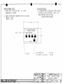
FUEL/AIR DATA COMPUTER
(ADC 200)
P/Ns:
962820-1, 962820-2, 962820-3
962820-1A, 962820-2A, 962820-3A
INSTALLATION MANUAL
REV R
Shadin Avionics
6831 Oxford Street
St. Louis Park, MN 55426
USA
Sales: (800)-328-0584
Customer Service: (800)-388-2849
www.shadin.com
P/N: IM2820
IM2820
IM2820RG.DOC, DIR. 962820
Shadin Avionics
INSTALLATION MANUAL
FUEL/AIR DATA COMPUTER
P/N 962820-1(A), 962820-2(A), 962820-3(A)
Rev: R
Page: i of vi
PAGE CONTROL CHART
SECTION
NO.
1.0
2.0
DESCRIPTION
PAGE
REVISION LOG
vi
OVERVIEW
1-1
1.1
1.2
1.3
1.4
1.5
1-1
1-1
1-2
1-3
1-3
The Manual
Product Information
System Configuration
Fuel Totalizer Configuration
F/ADC200, Argus Moving Map Configuration
FUEL AND AIR DATA SYSTEM SPECIFICATIONS
2-1
2.1
2.2
2.3
2.4
2.5
Input Data Range
Output Data Range
Dimensions
Power Requirements
Output Data
2.5.1 Serial Output Data Parameters
Limitations
2.6.1 Warm-up Time
2.6.2 Supplemental Equipment
2.6.3 Static/Pitot Source Error Correction (SSEC/PSEC)
2.6.4 SSEC/PSEC Listing
2.6.4 SSEC/PSEC Listing (Continued)
2.6.4 SSEC/PSEC Listing (Continued)
2.6.4 SSEC/PSEC Listing (Continued)
2.6.4 SSEC/PSEC Listing (Continued)
2-1
2-1
2-5
2-5
2-5
2-5
2-6
2-6
2-6
2-7
2-7
2-8
2-9
2-10
2-11
Part Numbering Scheme
Electrical Interface Specifications
2.8.1 Heading Interface
2.8.2 Fuel Flow Interfaces
2.8.2.1 Digital Fuel Flow
2.8.2.2 Sine Wave Fuel Flow
2.8.2.3 DC Voltage Fuel Flow
Statistical Specifications
2.9.1 Mean Time Between Failures
2-12
2.6
2.7
2.8
2.9
2-13
2-13
2-13
2-14
2-14
2-14
3.0
CERTIFICATION
3-1
4.0
PLACING AN ORDER
4-1
IM2820
IM2820RG.DOC, DIR. 962820
Shadin Avionics
INSTALLATION MANUAL
FUEL/AIR DATA COMPUTER
P/N 962820-1(A), 962820-2(A), 962820-3(A)
Rev: R
SECTION
NO.
5.0
DESCRIPTION
Page: ii of vi
PAGE
INSTALLATION PROCEDURE
5-1
5.1
5.2
5.3
5.4
5.5
5.6
5.7
5.8
5.9
5-1
5-1
5-1
5-2
5-3
5-4
5-5
5-6
5-6
General
F/ADC Location Selection
Mounting the F/ADC
Mounting the OAT Probe
Connection to the Fuel Flow Sensor
Connection to the Heading Source
Connection to the Pitot and Static Lines
Connection to the Navigation Management System
Post Installation Checkout
6.0
OPERATING INSTRUCTIONS
6-1
7.0
INITIALIZATION
7-1
8.0
MAJOR COMPONENTS OF THE SYSTEM
8-1
9.0
CONFIGURING THE AIR DATA
9-1
9.1
9.2
9-1
9-2
9-3
9-3
9-4
9-5
9-5
9-6
9-7
9-8
9-9
9-9
9-10
9-11
9-12
9-13
9-13
9-14
9-15
9-16
9-17
9-18
Configuring with ‘ADSETUP User Manual’
Configuring Manually
Loopback Procedure 1 for S/W Version 93.00.16 - 93.00.29
Stage 0 Loopback Configuration
Stage 1 Loopback Configuration
Loopback Procedure 2 for S/W Version 93.00.51 – 93.00.71
Stage 0 Loopback Configuration
Stage 1 Loopback Configuration
Stage 2 Loopback Configuration
Stage 3 Loopback Configuration
Loopback Procedure 3 for S/W Version 93.00.77
Stage 0 Loopback Configuration
Stage 1 Loopback Configuration
Stage 2 Loopback Configuration
Stage 3 Loopback Configuration
Loopback Procedure 4 for S/W Version 93.00.82 +
Stage 0 Loopback Configuration
Stage 1 Loopback Configuration
Stage 2 Loopback Configuration
Stage 3 Loopback Configuration
Stage 4 Loopback Configuration
Select No Delay
IM2820
IM2820RG.DOC, DIR. 962820
Shadin Avionics
INSTALLATION MANUAL
FUEL/AIR DATA COMPUTER
Rev: R
10.0
P/N 962820-1(A), 962820-2(A), 962820-3(A)
SETTING THE K-FACTOR
Table 1 - Analog K-Factor Settings Table 1
Table 2 - Digital K-Factor Settings Table 2 (Matrix 0)
Table 2 - Digital K-Factor Settings Table 2 (Matrix 0)
Table 2 - Digital K-Factor Settings Table 2 (Matrix 0)
Table 3 - Alternate Digital-K Factor Setting Table 3 (Matrix 1)
Page: iii of vi
10-1
10-2
10-3
10-4
10-5
10-6
IM2820
IM2820RG.DOC, DIR. 962820
Shadin Avionics
INSTALLATION MANUAL
FUEL/AIR DATA COMPUTER
Rev: R
11.0
P/N 962820-1(A), 962820-2(A), 962820-3(A)
Page: iv of vi
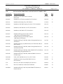
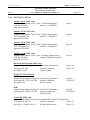
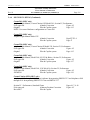
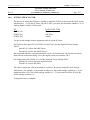
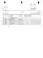
INSTALLATION DRAWINGS AND INSTALL KIT PARTS LISTS
Drawing No.
Description/Part Number
DATE
REV
4005-642
Installation, Sine/Square Wave Converter,
P/N 631201
03/03/10
B
4028-005
Installation, OAT Probe Assembly Kit, P/N 681201-1
02/14/05
C
4028-411
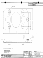
Installation, Mounting Tray, P/N 542801A
12/30/99
B
4028-604
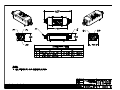
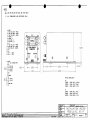
Installation, ADC200 Frequency/Level Int. FF, P/N 962820-1
08/31/95
–
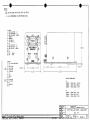
4028-605
Installation, ADC200 Sine wave FF, P/N 962820-2
08/31/95
–
4028-606
Installation, ADC200 DC FF, P/N 962820-3
08/31/95
–
4028-607
Installation Wiring, Fuel/Air data Computer
(ADC200) to OAT/Heading System
09/13/95
A
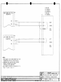
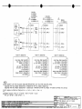
4028-608
Installation Wiring, Fuel/Air data Computer
(ADC200) to Fuel System
09/13/95
A
4028-943
Installation Wiring, F/ADC200, 2000 to Navigational Receivers
with RS-232
01/17/05
C
4028-944
Installation Wiring, Loop-Back Harness for F/ADC200, 2000, DSub Connector
09/19/05
C
4028-946
Installation Wiring, F/ADC200, 2000 to Navigational Receivers
with RS-422, RS-485
03/11/03
A
4028-947
Installation Wiring, F/ADC200, 2000, Shadin Fuel Flow Indicators
to Bendix/King Navigational Receiver
03/11/03
A
4028-948
Installation Wiring, F/ADC200, 2000 and Shadin Converter to
Eventide Argus
02/14/05
A
4028-A80
Label, ADC 200/2000 Access Cover, P/N 712801
02/14/05
A
4070-005
Installation, Serial to Argus 5000/7000 Converter,
P/N 937000-03
02/14/05
B
N/A
Parts List, OAT Probe Assembly Kit, P/N 681201-1
04/06/07
H
N/A
Parts List, Install Kit, F/ADC 200, P/N IK9628
04/06/07
D
4028-B94
Installation Wiring, F/ADC 200, 2000 Shadin FF Indicators to
Garmin 430/530
04/29/11
B
IM2820
IM2820RG.DOC, DIR. 962820
Shadin Avionics
INSTALLATION MANUAL
FUEL/AIR DATA COMPUTER
Rev: R
11.0
Drawing No.
P/N 962820-1(A), 962820-2(A), 962820-3(A)
Page: v of vi
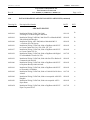
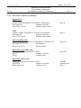
INSTALL DRAWINGS AND INSTALL KITS PARTS LISTS (continued)
Description/Part Number
DATE
REV
AIRCRAFT SPECIFIC
4028-818
Installation Wiring, F/ADC-200, 2000
w/Analog FF to Beech KingAir Indicators
03/11/03
B
4028-819
Installation Wiring F/ADC200, 2000 Sine FF to Mitsubishi MU300 & Model 400 Beechjet
Installation Wiring, ADC 200(2000) to Mitsubishi MU-2
w/Foxboro PC-620 System
Installation Wiring, F/ADC200, 2000 or DigiData with DC FF
to Cessna Citation 500, 501, 550, S550, 551, 552
Installation Wiring, F/ADC200, 2000 or DigiData with DC FF
to Cessna Citation 525 Jet
02/14/05
B
02/14/05
B
02/14/05
A
02/14/05
A
4028-938
Installation Wiring, F/ADC200, 2000 or DigiData with Digital
FF to BomBardier LearJet 24, 25D
01/17/05
A
4028-939
Installation Wiring, F/ADC200, 2000 with Sine FF to Rockwell
Commander 690 and 695
02/14/05
A
4028-940
Installation Wiring, F/ADC200, 2000 or DigiData with DC FF
to Raytheon Beechjet 400A Aircraft
02/14/05
A
4028-941
Installation Wiring, F/ADC200, 2000 or DigiData with DC FF
to Westwind 1124 Models
02/14/05
A
4028-942
Installation Wiring, F/ADC200, 2000 to Fairchild SA226 Series
Aircraft
01/17/05
A
4028-949
Installation Wiring, F/ADC200, 2000 to Aerospatiale AS365N2
Dauphin
02/14/05
A
4028-950
Installation Wiring, F/ADC200, 2000 to Aerospatiale AS332
Super Puma
02/14/05
A
4028-A29
Installation Wiring, F/ADC200, 2000 or DigiData with DC FF
Piper Cheyenne PA31T
01/17/05
C
4028-909
4028-936
4028-937
IM2820
IM2820RG.DOC, DIR. 962820
Shadin Avionics
INSTALLATION MANUAL
FUEL/AIR DATA COMPUTER
P/N 962820-1(A), 962820-2(A), 962820-3(A)
Rev: R
Page: vi of vi
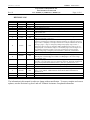
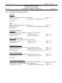
REVISION LOG
REV.
–
A
B
C
D
E
DATE
6/08/95
9/12/95
6/09/97
6/23/97
3/27/98
12/09/98
APP’D
RR
SES
KCL
KCL
KCL
KCL
CHANGE
Release
Miscellaneous updates
4 stage loop back procedure, Report to 4028B, Expand Index
Revise Limitations Section
Format change, SSEC listing, software configuration update, new installation DWGs.
Update pages 1-1, 9-9, 10-2, DWG 4028-944 and 4070-005 and include DWG’s 4028A29 and 4028-A80.
Updated Drawings 4028-411 and 4028-A29, and Install Kit P/N IK9628
Added Bendix B & Garmin, Format G, to page 9-7. Added one more Ragen
Indicator/Transmitter to page 11-31.
Page 1-1 & 1-3 changed to add Garmin 430/530 GPS. Page 2-1 changed by OAT
tolerance, IVS changing to 10,000 fpm, and Pitot and IAS set to 18 knots for low speed.
Page 2-6 & 2-7 changed by correcting LearJet HS-125 to Raytheon Hawker HS-125 and
moving to page 2-7. Page 5-1 changed by adding TSO paragraph. Page 5-2 & 8-1
changed by OAT kit. Page 5-4 changed by adding Sandel hdg source. Page 9-1 & 9-2
changed by SW version numbers. Pages 9-5 & 9-8 (blank pages) removed. Pages 9-9 to
9-12 added for loopback procedure 3. New page 9-8 changed to remove Switch 4
ARINC setting. Page iv changed by OAT kit, 4028-411, 4028-943, and 4028-B94.
Add sections 2.8 and 2.9. Update sections 2.0, 5.1 and 5.7.
F
3/16/99
KCL
G
1/31/00
EDJ
H
9/18/00
EDJ
J
11/03/00
KCL
K
08/30/02
EDJ
L
02/25/05
ZK
M
N
09/22/05
04/06/07
ZK
ZK
P
04/29/08
EDJ
Updated all sections with P/N 962820-1(A), -2(A), & -3(A), updated Section
2.2, 2.7, 3.0, and 9.0. Added Antonov and Yak-40 SSEC information in
Section 2.6.4.
R
04/29/11
ZK
Updated Drawings 4028-B94 and 4005-642.
Added P/N 681201-1 OAT probe installation and parts list to page iv
drawing list. Corrected page 10-3 Table 2. Added pages 9-13 to 9-21. Page
9-13 became 9-22.
Changed Company name. Removed 681201A-1 dwg, parts list, and 93.00.79 Loopback
procedure. Corrected Table 1 page 10-2, 4028-A29, 4028-938, 4028-942, and 4028-943.
Incorporated updated IK9628 and P/N 681201-1 Parts list. Updated Section 11.0.
Updated 4028-944 and section 2.2. Corrected typos on pages 2-3, 5-1 and 10-5.
Changed Company name. Updated 681201-1 and IK9628 parts list.
The information in this manual is subject to change without notification. To ensure complete and current
updates, note the Revision Log above and call Technical Assistance for updated information.
IM2820
IM2820RG.DOC, DIR. 962820
Shadin Avionics
INSTALLATION MANUAL
FUEL/AIR DATA COMPUTER
P/N 962820-1(A), 962820-2(A), 962820-3(A)
Rev: R
1.0
OVERVIEW
1.1
The Manual
Page: 1-1
This manual is designed to facilitate the installation of the Shadin Fuel/Air data Computer (ADC
200).
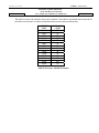
1.2
Product Information
The Shadin ADC 200 system is designed to provide a combined source of fuel and air data. Listed
below are the navigational systems that the ADC 200 has been designed to be compatible with.
Receives Serial Data from:
Magellan
Skynav 5000
ARNAV
STAR 5000
FMS 7000
R5000
Trimble
2000/2000A
2100/3000
3100/2101
Bendix King
KLN90
KLN90A
KLN90B
KLN89/89B
KLN900
Garmin
150, 155, 155XL, 165
230, 230XL
300, 300XL
430, 530
BFGoodrich
Pronav LNS 6000
IIMorrow
611, 612, 618
NMS 2001
800, 820, 360
GX50, 55, 60
Transmits Serial Data to:
ARNAV
Magellan
Bendix/King
Trimble
Garmin
Note: To find out which particular receiver
models have Air data receive capability,
contact the manufacturers.
IM2820
IM2820RG.DOC, DIR. 962820
Shadin Avionics
INSTALLATION MANUAL
FUEL/AIR DATA COMPUTER
P/N 962820-1(A), 962820-2(A), 962820-3(A)
Rev: R
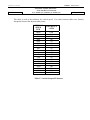
1.3
Page: 1-2
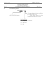
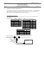
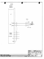
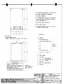
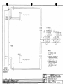
System Configuration
The Fuel/Air data system is a remote mounted box, which is connected to the GPS receiver via
serial data. It is also connected to the pitot and static line, OAT probe, fuel flow sensors and the
aircraft heading source.
PITOT
STATIC
NAV
RECEIVER
FUEL/AIRDATA
OAT
MAG. HEADING
L. ENGINE
FUEL FLOW
R. ENGINE
FUEL FLOW
SYSTEM CONFIGURATION
IM2820
IM2820RG.DOC, DIR. 962820
Shadin Avionics
INSTALLATION MANUAL
FUEL/AIR DATA COMPUTER
P/N 962820-1(A), 962820-2(A), 962820-3(A)
Rev: R
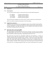
1.4
Page: 1-3
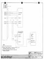
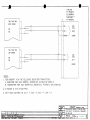
Fuel Totalizer Configuration
Shown below is an optional system configuration utilizing a Shadin Fuel Flow Indicator. Note
that the only navigational receivers supported in this configuration are the Bendix/King KLN
series and the Garmin 430/530. Consult Drawing Number 4028-947 contained in section 11 for
installation information on the Bendix/King KLN series, and Drawing Number 4028-B94 for the
Garmin 430/530.
Garmin
Bendix/King
430,
530
KLN90, A, B
KLN89
KLN900
Shadin
RS-232
DigiFlo
MiniFlo
MicroFlo
L. Fuel Flow Transmitter
R. Fuel Flow Transmitter
or
Shadin
RS-232
1.5
F/ADC200
RS-232
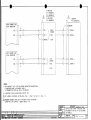
F/ADC200, Argus Moving Map Configurations.
Shown below is the system configuration that supports output to a Eventide Argus moving map
using the Shadin serial to serial data converter P/N 937000-03. The fuel and Air data are
displayed on the Eventide-Argus moving map. Consult Drawing numbers 4070-005 and 4028-948
contained in section 11.
Shadin
RS-232 or RS422
F/ADC200
RS-232 or RS422
Shadin
Navigational
Receiver
RS-232
Converter
P/N 937000-03
Eventide
Argus
M oving M ap
P/N 5000
P/N 7000
IM2820
IM2820RG.DOC, DIR. 962820
Shadin Avionics
INSTALLATION MANUAL
FUEL/AIR DATA COMPUTER
P/N 962820-1(A), 962820-2(A), 962820-3(A)
Rev: R
2.0
FUEL AND AIR DATA SYSTEM SPECIFICATIONS
2.1
Input Data Range
Pitot
Static
OAT
Heading
Fuel Flow
K Factor
2.2
Page: 2-1
18 to 350 kt.
-1000 to 55,000 ft.
-60°C to, +60°C
0 - 360°
1 to 450 GPH Range Selected
500 to 130000 PPG Continuous
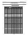
Output Data Range
PARAMETER
IAS
P.ALT
OAT
TRUE HEADING
MAGNETIC HEADING
IVS
TAS
MACH
WIND SPEED
WIND DIRECTION
FUEL FLOW
Accuracy*
Table A
Table B
±1.5°C per TSO
±2°
±1°
Table C
Table A
Table D
±5 kts.
±10°
±2%
RANGE
20 to 350 kts.
–1000 to 50000 ft.
–60°C to +60°C
0 - 360 degrees
0 - 360 degrees
± 10,000 ft./min.
20 - 600 kts.
.2 - .95
5 - 360 kts.
0 - 360 degrees
1-450 GPH
* Listed accuracies are after warm-up is complete per the ambient temperatures listed in Section 2.6.1
This table is used as the tolerance for both IAS and TAS. For values between table rows, linearly
interpolate between the adjacent table points.
AIRSPEED
KNOTS
TOLERANCE
± KNOTS
50
80
100
120
150
200
250
300
350
400
450
5.0
3.0
2.0
2.0
2.0
2.0
2.4
2.8
3.2
3.6
4.0
Table A - Calibrated Airspeed Tolerance
IM2820
IM2820RG.DOC, DIR. 962820
Shadin Avionics
INSTALLATION MANUAL
FUEL/AIR DATA COMPUTER
Rev: R
P/N 962820-1(A), 962820-2(A), 962820-3(A)
Page: 2-2
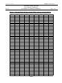
This table is used as the tolerance for pressure altitude. Note that for an altitude between points in
the tables, the tolerance is linearly interpolated between the adjacent table points.
ALTITUDE
FEET
TOLERANCE
± FEET
0
1000
2000
3000
4000
5000
8000
11000
14000
17000
20000
30000
40000
50000
25
25
25
25
25
25
30
35
40
45
50
75
100
125
Table B -Pressure Altitude Tolerance
IM2820
IM2820RG.DOC, DIR. 962820
Shadin Avionics
INSTALLATION MANUAL
FUEL/AIR DATA COMPUTER
Rev: R
P/N 962820-1(A), 962820-2(A), 962820-3(A)
Page: 2-3
This table is used as the tolerance for vertical speed. For values between table rows, linearly
interpolate between the adjacent table points.
VERTICAL
SPEED
FPM
20000
6000
4000
2000
1000
500
200
100
50
0
-50
-100
-200
-500
-1000
-2000
-4000
-6000
-20000
TOLERANCE
± FPM
1000
300
200
100
50
45
45
45
45
45
45
45
45
45
50
100
200
300
1000
Table C- Vertical Airspeed Tolerance
IM2820
IM2820RG.DOC, DIR. 962820
Shadin Avionics
INSTALLATION MANUAL
FUEL/AIR DATA COMPUTER
Rev: R
P/N 962820-1(A), 962820-2(A), 962820-3(A)
Page: 2-4
This table is used as the tolerance for MACH Number. For values between table rows, linearly
interpolate between the adjacent table points.
ALTITUDE
TOLERANCE
FEET
MACH
± MACH
0
.3
.012
.4
.012
.5
.010
.6
.0075
.4
.012
.5
.010
.6
.0075
.7
.005
.4
.012
.5
.010
.6
.0075
.7
.005
.6
.0075
.7
.005
.80
.005
.90
.005
.95
.0075
.70
.005
.80
.005
.90
.005
.95
.0075
.75
.005
.90
.005
.95
.0075
1.00
.015
10,000
20,000
30,000
40,000
50,000
Table D - MACH Tolerance
IM2820
IM2820RG.DOC, DIR. 962820
Shadin Avionics
INSTALLATION MANUAL
FUEL/AIR DATA COMPUTER
P/N 962820-1(A), 962820-2(A), 962820-3(A)
Rev: R
2.3
Page: 2-5
Dimensions (including mounting rack)
Size: 6.3"L x 3.5"H x 3.1"W
Weight: 20 oz.
2.4
Power Requirements
System Power required: 28 VDC @ 1300 mA 14 VDC @ 900 mA
2.5
Output Data
Electric Format: RS-422 or RS-232
2.5.1
Serial Output Data Parameters
Fuel Group
Left Fuel Flow
Right Fuel Flow
Fuel Used Total
Total Fuel Used
Fuel Used Right
Fuel Used Left
Fuel Remaining
NM/Gal (ground)
Fuel to Destination
Fuel at Destination
Air data Group
Aircraft Type
Density Altitude
MACH Number
Drift Angle
True Air Speed (TAS)
Magnetic Heading
Indicated Air Speed (IAS)
Pressure Altitude
Wind Direction and Speed
Rate of Turn
Vertical Speed
True Air Temperature
Outside Air Temperature (OAT)
Note: Not all parameters will be available to all navigational receivers. Contact the manufacturer
for display capabilities.
IM2820
IM2820RG.DOC, DIR. 962820
Shadin Avionics
INSTALLATION MANUAL
FUEL/AIR DATA COMPUTER
P/N 962820-1(A), 962820-2(A), 962820-3(A)
Rev: R
Page: 2-6
2.6
Limitations
2.6.1
Warm-up time
The Fuel/Air data System requires a warm-up time that varies with ambient temperature:
70°C ambient
15°C ambient
-20°C ambient
-40°C ambient
5 minutes warm-up required
10 minutes warm-up required
15 minutes warm-up required
20 minutes warm-up required
If the ADC has been configured for a fuel flow delay, fuel flow and thus fuel used information
shall be unavailable at startup for the duration of the selected delay.
2.6.2
Supplemental equipment
All Shadin F/ADC(s) and ADC(s) are not designed to replace factory installed Air data fuel flow
systems or other gauges. They are not intended to be used as a primary system to drive altimeters
or airspeed indicators. The F/ADC fuel section is not a fuel quantity system and therefore reports
only what was manually entered by the operator.
2.6.3
Static Source Error Correction (SSEC),
Pitot Source Error Correction (PSEC)
For certain models of aircraft, the Fuel/Air data System will make corrections to pressure altitude
by compensating for static source error. For some of these models, the Fuel/Air data System will
make corrections to indicated airspeed by compensating for pitot source error.
The System does not provide true and absolute readings for all circumstances. It makes no
altitude corrections when the uncorrected IAS is below 100 knots, and it makes no airspeed
corrections when the uncorrected IAS is below 150 knots. It does not account for other factors,
such as the current useful weight, that contribute to static source error and pitot source error.
Rather, the Fuel/Air data System performs calculations based solely on indicated airspeed and
pressure altitude. The SSEC / PSEC corrections were derived from specific aircraft data referred
to in section 2.6.4. To configure the Shadin F/ADC for a specific aircraft model refer to section 9.
IM2820
IM2820RG.DOC, DIR. 962820
Shadin Avionics
INSTALLATION MANUAL
FUEL/AIR DATA COMPUTER
P/N 962820-1(A), 962820-2(A), 962820-3(A)
Rev: R
2.6.4
Page: 2-7
SSEC/PSEC LISTING
Antonov An-12 (SSEC only)
Airplane Flight Manual, An-12, Sect. 1 General Information
1991, MCA USSR
Subsect. 1.5. S&DSECs
approved 02/05/1992
Antonov An-24 (SSEC only)
Airplane Flight Manual, An-24, Sect. 6 Flight Characteristics
2001, Ukrainian SAA
Subsect. 6.7 S&DSECs
approved 03/29/2002
Antonov An-26 (SSEC only)
Airplane Flight Manual, An-26, Sect. 6 Flight Characteristics
2001, Ukrainian SAA
Subsect. 6.10 S&DSECs
approved 03/29/2002
Antonov An-30 (SSEC only)
Airplane Flight Manual, An-30, Sect. 6 Airplane Characteristics
1982, MCA USSR
Subsect. Flight Characteristics
approved 12/25/1979
Beechcraft Beechjet-400 (SSEC only)
Airplane Flight Manual, BeechJet 400, Section 6, Performance
FAA approved 1/86
Altitude Correction
Revision A9 14/92
Copilot System
Boeing 707-321B Advanced
SSEC
Airplane Flight Manual, Boeing 707, Section IV, Performance
FAA approved 3/27/69, D6-1588
Altitude Calibration
Revision 2/4/69
Pilot & Copilot
PSEC
Airplane Flight Manual, Boeing 707, Section IV, Performance
FAA approved 9/20/66, D6-1588
Airspeed Calibration
Pilot & Copilot
Page 9
Page 81
Page 53
Page 31
Page 6-14
Figure 6-8
Page 19
FLAPS UP
Page 18
FLAPS UP
Cessna 500 (SSEC only)
Airplane Flight Manual, Cessna/Citation Model 500, Section IV, Performance
FAA approved Aug 7/74
Altitude Correction
Figure 4-7
Revision 53 - Dated 11 Dec 85
Pilot & Copilot system
Page 4-17.1
IM2820
IM2820RG.DOC, DIR. 962820
Shadin Avionics
INSTALLATION MANUAL
FUEL/AIR DATA COMPUTER
Rev: R
P/N 962820-1(A), 962820-2(A), 962820-3(A)
Page: 2-8
2.6.4 SSEC/PSEC LISTING (Continued)
Cessna 501 (SSEC only)
Airplane Flight Manual, Cessna/Citation I SP Model 501, Section IV, Performance
FAA approved
Altitude Correction
Figure 4-5
Original
Pilot & Copilot system
Page 4-15
NOTE: Uses same Hardware configuration as Cessna 500
Cessna 525 (SSEC only)
Airplane Flight Manual Model 525
Altitude Correction
Pilot & Copilot system
Rept FT525-4
Page 47
Cessna 550 (SSEC only)
Airplane Flight Manual, Cessna/Citation II Model 550, Section IV, Performance
FAA approved
Altitude Correction
Figure 4-5
Original
Pilot & Copilot system
Page 4-15
Cessna 560 (SSEC only)
Airplane Flight Manual, Model 560, S/N 259 & Below, Section IV, Performance
FAA approved
Altitude Correction
Figure 4-5
Original
Pilot & Copilot system
Page 4-17
Cessna 560 (SSEC only)
Airplane Flight Manual, Model 560 , S/N 260 & Up, Section IV, Performance
FAA approved
Altitude Correction
Figure 4-5
56FMA-00
Pilot & Copilot system
Page 4-19
Cessna Citation S550 (SSEC only)
Airplanes -0115 through -0160 Except Airplanes Incorporating SBS550-32-7 and Airplanes -0001
through-0114 Incorporating SBS550-32-1 but not SBS550-32-7.
Section IV - Performance, Standard Charts
FAA approved
Altimeter Position Correction
Revision 37
Pilot & Copilot
Pages 4-17, 4-18
Figure 4-5
IM2820
IM2820RG.DOC, DIR. 962820
Shadin Avionics
INSTALLATION MANUAL
FUEL/AIR DATA COMPUTER
Rev: R
P/N 962820-1(A), 962820-2(A), 962820-3(A)
Page: 2-9
2.6.4 SSEC/PSEC LISTING (Continued)
Douglas DC-8
SSEC
Airplane Manual, Douglas DC-8, Section IV, Performance
FAA approved
Altitude Correction
DAC-33161 10/1/66
Pilot & Copilot system
PSEC
Airplane Manual, Douglas DC-8, Section IV, Performance
FAA approved
Airspeed Correction
DAC-33161 10/1/66
Pilot & Copilot system
Falcon 10 (SSEC only)
Airplane Flight Manual, Section 6. Performance, 7 Position Error
FAA approved 10/17/73
Position Error
Revision 14, 6/6/78
Pilot & Copilot
Falcon 20-C, D, E (SSEC only)
Maintenance Instruction Manual, 34-18-03
Sept 1/77
Altitude Correction
CS-143
Copilot system
Falcon 20-F (SSEC only)
Maintenance Instruction Manual, 34-18-03
DTM30528
Altitude Correction
DGAC Approved
Copilot system
Page 20
Page 11
Page 6-27
Page A48
Section 5
Subsection 20
Page 4
IM2820
IM2820RG.DOC, DIR. 962820
Shadin Avionics
INSTALLATION MANUAL
FUEL/AIR DATA COMPUTER
Rev: R
P/N 962820-1(A), 962820-2(A), 962820-3(A)
Page: 2-10
2.6.4 SSEC/PSEC LISTING (Continued)
Falcon 50
SSEC
Airplane Flight Manual, Section 5. Performance
Page 5.25.2
DGAC approved
Copilot (for A/C equipped with one ADC)
Revision 24
PSEC
Airplane Flight Manual, Section 5. Performance
Page 5.25.2
DGAC approved
Pilot (normal) and Copilot MACH Indicators
Revision 24
LearJet 24 (SSEC only)
Airplane Manual, LearJet Model 24, Section IV, Performance
FAA approved 3/17/66
Altitude Correction
Revised 7/19/68
Pilot & Copilot system
Figure 4-10
Page 4-16
LearJet 25D (SSEC only)
Airplane Manual, LearJet 25D/F AFM, Performance
FAA approved 10/14/86
Altitude Correction
FM-018 Release A
Copilot system
Figure 5-10
Page 5-18
LearJet 35 (SSEC only)
Flight Manual, LearJet 35, Normal System, Flaps up, Gear up
Page 5-18
FAA approved, 4/30/76
Altitude Position Correction
Figure 5-10
Reissued 2/25/81
Pilot’s Altimeter- STBY & Copilot’s Altimeter
LearJet 55 (SSEC only)
Gates LearJet 55, APM, Performance Data, Flaps up, Gear up
FAA approved, 3-17-81
Altitude Position Correction
Change 13
Page 5-20
Figure 5-11
Lockheed Jetstar (SSEC only)
Airplane Flight Manual, Performance Data, Weight = 32,000 Lb., Clean Configuration: Leading
Edge Flaps up, Trailing Edge Flaps up, Landing Gear up
Page 4-25
FAA approved, 12/14/76
Altimeter Installation Correction
Figure 4-15
IM2820
IM2820RG.DOC, DIR. 962820
Shadin Avionics
INSTALLATION MANUAL
FUEL/AIR DATA COMPUTER
Rev: R
P/N 962820-1(A), 962820-2(A), 962820-3(A)
Page: 2-11
2.6.4 SSEC/PSEC LISTING (Continued)
Mitsubishi MU-300 (SSEC only)
Airplane Flight Manual, Diamond IA, Section 6, Performance
FAA approved Jan 11/84
Altitude Correction
Copilot system
Figure 6-8
Page 6-20
Raytheon Hawker HS-125-3A (SSEC only)
Airplane Manual,
Document No. H.S.1.10
Static Position Error
CAA Approved
Correction to Altimeter
Section 5
Figure 5-4
Page 13
Raytheon Hawker HS125-700A (SSEC only)
125 Crew Manual, First Officer, Section 2, Flaps Retracted
Static Position Correction to Altimeter
Revision :G, 4/77
Sabreliner 60 (SSEC only)
Sabreliner Pilot’s Manual, SR 75-064, Weight = 16,000 Lb.
9/1/76
Altitude Calibration
Page 2-30
Figure 6
Figure 7-2
Sabreliner 65 (SSEC only)
Pilots Manual, SR-78-028
Altitude Correction
Pilot & Copilot system
Westwind 1124A (SSEC only)
Airplane Flight Manual, 1124A , Section V, Performance
CAA approved
Altitude Correction
Figures 5-13, Flaps 0
Copilot system
NOTE: Gross Weight averaged at 18,750 lbs.
Yak-40 (SSEC only)
Airplane Flight Manual, Sect. 7.1.3.
Yak-40, 1995
Altitude correction
Figures 7-1 through 7-5
265-65-7-31,32A,33
Pages V-25
Page 7
IM2820
IM2820RG.DOC, DIR. 962820
Shadin Avionics
INSTALLATION MANUAL
FUEL/AIR DATA COMPUTER
Rev: R
2.7
P/N 962820-1(A), 962820-2(A), 962820-3(A)
Page: 2-12
Part Numbering Scheme
P/N 962820 - X A
“A” means software has been certified to
RTCA/DO-178B Level D
“ “ blank means software has been
certified to RTCA/DO-178A Level II
ADC200 D-SUB Connector
Fuel Sensor Type
X=1, Frequency/Level Interface
X=2, Sine Wave
X=3, DC
IM2820
IM2820RG.DOC, DIR. 962820
Shadin Avionics
INSTALLATION MANUAL
FUEL/AIR DATA COMPUTER
P/N 962820-1(A), 962820-2(A), 962820-3(A)
Rev: R
2.8
Page: 2-13
Electrical Interface Specifications
The specifications for the heading and fuel flow interfaces are listed in this section.
2.8.1
Heading Interface
The heading interface follows the ARINC 407 standard (line voltage of 11.8 Vrms).
Synchro Leg
H
X
Y
2.8.2
Input Impedance
10 kohm
17 kohm
17 kohm
Fuel Flow Interfaces
There are three basic types of fuel flow interfaces supported. The interface type is defined in the
ADC2000 part number. Refer to section 2.7 for the part numbering scheme.
2.8.2.1 Digital Fuel Flow Interface
The are two possible installations for the digital fuel flow interface, the first is that the ADC is
connected to a dedicated fuel flow transmitter, and the second is that the ADC is connected into a
fuel flow system.
Dedicated Transmitter
Fuel Flow Interface Input Impedance
47 kohm
Shared Transmitter
Under normal operating conditions the voltage swing (the signal amplitude) can be calculated
using Vs = [R/(R + 47 k)]*5 Vdc – 0.5Vdc, where R is the input impedance of the aircraft fuel
flow indicator.
For example with an input impedance R = 1 Mohm, the voltage swing Vs = 4.27 Vdc
With the fuel flow information encoded in frequency and not amplitude, the loading effects do not
produce an error provided the aircraft indicator can detect the signal transitions.
IM2820
IM2820RG.DOC, DIR. 962820
Shadin Avionics
INSTALLATION MANUAL
FUEL/AIR DATA COMPUTER
P/N 962820-1(A), 962820-2(A), 962820-3(A)
Rev: R
Page: 2-14
2.8.2.2 Sine Wave Fuel Flow Interface
The interface source signal amplitude varies with frequency. Listed in the table below are the
input impedance vs. peak to peak input voltages of the ADC2000 under normal operating
conditions.
Input Impedance
2 Mohm
24.5 kohm
Input Voltage
Input voltage less than or equal to 1.0 Vpp
Input voltage greater than 1.0 Vpp
Maximum Input Voltage
10 Vpp
2.8.2.3 DC Voltage Fuel Flow Interface
The DC voltage fuel flow interface has a differential input. The specifications under normal
operating conditions are listed below.
Positive input
Negative input
greater than 100 Mohm
greater than 100 Mohm
Maximum Input Voltage
10.2 Vdc
2.9
Statistical Specifications
2.9.1
Mean Time Between Failures
MTBF:
17,660 hours
IM2820
IM2820RG.DOC, DIR. 962820
Shadin Avionics
INSTALLATION MANUAL
FUEL/AIR DATA COMPUTER
P/N 962820-1(A), 962820-2(A), 962820-3(A)
Rev: R
3.0
Page: 3-1
CERTIFICATION
TSO -C106, -C44a
Environmental Categories RTCA/DO-160B
Temp. ALT
Temp. Variation
Humidity
Shock & Vibration
Magnetic Effect
Power Input
Voltage Spike
AF Conducted Susceptibility
Induced Signal Susceptibility
RF Susceptibility
RF Emission
F2
B
A
P, K, S, M, N, O
B
B
B
B
B
A
B
Software Certification
P/N 962820-1, 962820-2, and 962820-3 conforms to level II as defined by RTCA/DO-178A.
P/N 962820-1A, 962820-2A, and 962820-3A conforms to level D as defined by RTCA/DO178B.
IM2820
IM2820RG.DOC, DIR. 962820
Shadin Avionics
INSTALLATION MANUAL
FUEL/AIR DATA COMPUTER
Rev: R
4.0
P/N 962820-1(A), 962820-2(A), 962820-3(A)
Page: 4-1
PLACING AN ORDER
Please know the aircraft year and model number, its serial number, and the engine make and
model number when you call to place orders. Information on the fuel flow system previously
installed in the aircraft and any communication interface (RS-232 or RS-422) information may
also prove useful.
We may request a wiring diagram of the aircraft's fuel flow system and transducer and/or Kfactors.
IM2820
IM2820RG.DOC, DIR. 962820
Shadin Avionics
INSTALLATION MANUAL
FUEL/AIR DATA COMPUTER
P/N 962820-1(A), 962820-2(A), 962820-3(A)
Rev: R
5.0
INSTALLATION PROCEDURE
5.1
General
Page: 5-1
The conditions and tests required for TSO approval of this article are minimum performance
standards. It is the responsibility of those installing this article either on or within a specific type
or class of aircraft to determine that the aircraft installation conditions are within the TSO
standards. TSO articles must have separate approval for installation in an aircraft. The article
may be installed only if performed under 14 CFR part 43 or the applicable airworthiness
requirements.
All work must conform to AC 43.13-1B; latest release.
5.2
F/ADC Location Selection
The Fuel Air data Computer should be mounted in a dry, temperature stable location with enough
distance from motors, pulse generating equipment, relays and cables carrying high DC or AC
current to avoid interference with low level signals of the OAT and fuel flow.
The equipment may be installed in non-pressurized and non-controlled temperature locations.
In considering the location, keep in mind that the F/ADC requires signals from the fuel flow, the
OAT probe, heading system and the pitot and static lines. Placement in the front section of the
aircraft is favorable, in order to avoid running all of these signals to the tail of the aircraft.
5.3
Mounting the F/ADC
The computer should be mounted per Drawing 4028-604, -605, -606, and Drawing 4028-411,
using the recommended hardware. Any orientation is acceptable. Make sure that the computer is
not the lowest point in the pitot and static system, to reduce the chances of collecting moisture or
water in it. Form a water trap, if necessary.
IM2820
IM2820RG.DOC, DIR. 962820
Shadin Avionics
INSTALLATION MANUAL
FUEL/AIR DATA COMPUTER
P/N 962820-1(A), 962820-2(A), 962820-3(A)
Rev: R
5.4
Page: 5-2
Mounting the OAT Probe
1.
Refer to Drawing 4028-005 and OAT Probe Assy Kit P/N 681201-1. Use the supplied
stiffener to support the probe. Keep the probe away from transmitting antennas and static
ports of autopilots to avoid interference.
2.
Refer to Drawing 4028-607: +5V is supplied to the OAT probe from (red wire) J1:15. The
OAT signal is the white (or black) wire from J1:14.
3.
The sun shield must be installed for proper indication of OAT.
4.
For single engine installation, avoid mounting the OAT probe on the belly of the aircraft to
avoid erroneous reading due to the presence of hot exhaust gases.
5. Below is an OAT °C to microampere conversion chart. The amperage can be measured by
connecting an ammeter in series between the signal wire of the OAT probe and the ADC200.
This information is provided for trouble shooting purposes only.
OAT ºC
-60
-50
-40
-30
Input µA
213
223
233
243
OAT ºC
-20
-10
0
+10
Input µA
253
263
273
283
OAT ºC
+20
+30
+40
+50
Input µA
293
303
313
323
OAT ºC
+60
Input µA
333
1°C = 1 μA
IM2820
IM2820RG.DOC, DIR. 962820
Shadin Avionics
INSTALLATION MANUAL
FUEL/AIR DATA COMPUTER
P/N 962820-1(A), 962820-2(A), 962820-3(A)
Rev: R
5.5
Page: 5-3
Connection to the Fuel Flow Sensor
1.
If the aircraft is not equipped with a fuel flow source, refer to the STC covering the
installation of the fuel flow transducer on the engine.
2.
When connecting to any fuel transducer, Shadin recommends using a 3 conductor, 22 gauge,
shielded wire with the shield terminated at the Air Data only.
3.
Note that for single engines all fuel flow types should use left side inputs only.
4.
*Install the transducers according to the engine STC, using Drawing 4028-608 (Freq. Option)
to connect the fuel flow transducer to the computer.
5.
*If the aircraft is equipped with a digital fuel flow transducer (P/N 680501), use Drawing
4028-608 (High-Level Option) and the STC drawing covering the installation.
6.
Before hooking to an existing fuel system in a turbine or jet application, consult all
installation drawings contained in this manual.
7.
*If the aircraft is equipped with a DC fuel flow system, use Drawing 4028-608 (DC Fuel
Flow Option) and the STC covering the installation.
8.
*If the aircraft is equipped with a sine wave pickup coil type of fuel flow transducer, use
Drawing 4028-608 (Sine Wave Signal). Use the Converter, P/N 631201. Note that if this is a
new installation, use part number 962820-2(A) ADC200.
9.
Install the sine to square converter, P/N 631201, between the fuel flow transducer and the
F/ADC as depicted in 4028-608 and 4005-642.
10. Make sure that the system is initialized with the proper transducer K factor for a digital or
sine systems and with the proper airframe make and model for the DC fuel flow systems. See
the attached tables in section 10.0.
* Consult section 11 for specific aircraft installation wiring drawings.
IM2820
IM2820RG.DOC, DIR. 962820
Shadin Avionics
INSTALLATION MANUAL
FUEL/AIR DATA COMPUTER
P/N 962820-1(A), 962820-2(A), 962820-3(A)
Rev: R
5.6
Page: 5-4
Connection to the Heading Source
The system is designed to interface with any ARINC-407 heading system (X,Y,Z) with no effect
on the heading system or the bootstrap.
XYZ
Heading
ARINC
407
FUEL
Air
Data
J1
Collins
328A-2A
2P1
X
Y
Z
H
C
5
4
7
6
7
11
4
3
26
22
Collins
HSI331A
P1
S
T
U
V
W
Collins
MCS
65
P1
Collins
328A-5
25
40
24
6
5
32
22
12
53
57
King
KI525A
P2
s
v
t
r
u
King
KSG105
P1
t
p
k
c
f
Sperry
Gyrosyn
Comp.
P1
SigmaTek
DG
L
M
K
H
J
A
B
D
E
H
Sandel
SN3308
P1
P2
25
6
4
4
4
The C wire (AC common) and the Z wire must be connected together at the source (bootstrap).
IM2820
IM2820RG.DOC, DIR. 962820
Shadin Avionics
INSTALLATION MANUAL
FUEL/AIR DATA COMPUTER
P/N 962820-1(A), 962820-2(A), 962820-3(A)
Rev: R
5.7
Page: 5-5
Connection to the Pitot and Static Lines
The pitot static line should be cut and a tee installed, to tap into these lines. Use the appropriate
type of fittings to match the type installed in the aircraft. Refer to CFR part 43, appendix E for
approved practices in installing and verifying these connections.
PITOT/STATIC adapter helpful hints
To make an adapter for the Shadin ADC200, the following parts could be used. It is recommended to use all
aluminum fittings.
Existing Pitot/Static lines
AN910-1D
AN816-2D
#2 Hose(with female fittings)
AN910 DASH NUMBER
BRASS
ALUM. ALLOY
-1
-2
-3
-4
-6
-8
-1D
-2D
-3D
-4D
-6D
-8D
PIPE
SIZE
AN816 DASH NUMBER
STEEL ALUM. ALLOY
1/8”
1/4”
3/8”
1/2”
3/4”
1”
-2
-3
-4
-5
-6
-8
-10
-12
-16
MS20825 TEE
STEEL
ALUM. ALLOY
-2
-3
-4
-5
-2D
-3D
-4D
-5D
-2D
-3D
-4D
-5D
-6D
-8D
-10D
-12D
-16D
TUBE
O. D.
PIPE
THREAD
1/8”
3/16”
1/4”
5/16”
1/8”
1/8”
1/8”
1/8”
TUBE
O. D.
PIPE
THREAD
1/8”
3/16”
1/4”
5/16”
3/8”
1/2”
5/8”
3/4”
1”
1/8”
1/8”
1/8”
1/8”
1/4”
3/8”
1/2”
3/4”
1”
HOSE: Stratoflex 193-2 or Aeroquip 306-2 with MS27404 (P/N 311-2D) on each end.
Air source
MS20825 Tee
AN910
AN816
MS27404
ADC200
IM2820
IM2820RG.DOC, DIR. 962820
Shadin Avionics
INSTALLATION MANUAL
FUEL/AIR DATA COMPUTER
P/N 962820-1(A), 962820-2(A), 962820-3(A)
Rev: R
5.8
5.9
Page: 5-6
Connection to the Navigation Management System
1.
Use the appropriate installation wiring diagram (4028-943 or -946) to connect the Fuel Air
data Computer's Connector J2 to the navigation management system.
2.
A 2 amp. circuit breaker should be used for powering the system. Mark the C/B "F/ADC" by
engraving, painting or other approved method.
3.
Keep the cables away from power cables, DME and transponder cables.
4.
Refer to the specific Nav Receiver Installation Manuals for details.
Post Installation Checkout
1.
The pitot and static system must be checked for leaks.
2.
Operate the Navigation Management System; select the altitude and airspeed pages. Use the
static and pitot test system to check the accuracy of the readout in the Navigation
Management System pages.
3.
Select heading page. Slew compass through 360°. The error should be within +1°.
4.
Select the OAT page. Compare to the reported ambient temperature. The error should be
+2°C.
5.
Run the engines and select the fuel flow page. Compare the fuel flow readout with the engine
manufacturer's fuel flow charts under the ambient temperature and pressure conditions.
IM2820
IM2820RG.DOC, DIR. 962820
Shadin Avionics
INSTALLATION MANUAL
FUEL/AIR DATA COMPUTER
P/N 962820-1(A), 962820-2(A), 962820-3(A)
Rev: R
6.0
Page: 6-1
OPERATING INSTRUCTIONS
1.
Power the avionics DC buss and the Navigation Management System.
2.
After the warm-up period density altitude and PALT are available. IAS will be available but
will be out of range until actual airspeed is available. Winds aloft will be available if IAS >
40 Kts and magnetic heading is within 40° of magnetic track.
3.
Fuel Flow, Fuel Used, Fuel Remaining, Heading and OAT will be available after power-up.
4.
Refer to the specific Nav Receiver Operator's Manual for page selection of various data.
IM2820
IM2820RG.DOC, DIR. 962820
Shadin Avionics
INSTALLATION MANUAL
FUEL/AIR DATA COMPUTER
P/N 962820-1(A), 962820-2(A), 962820-3(A)
Rev: R
7.0
Page: 7-1
INITIALIZATION
1.
The system requires initialization of K factor for fuel flow transducers or aircraft model for
DC fuel flow sensors. Refer to Table 1 analog for fuel flow and Table 2 or Table 3 for
digital or sine fuel flow.
2.
Refer to the specific Navigational Receiver Operator Manuals for the serial port set up.
IM2820
IM2820RG.DOC, DIR. 962820
Shadin Avionics
INSTALLATION MANUAL
FUEL/AIR DATA COMPUTER
P/N 962820-1(A), 962820-2(A), 962820-3(A)
Rev: R
8.0
MAJOR COMPONENTS OF THE SYSTEM
1.
2.
3.
Nav Receiver Input/Output
Fuel/Air data Computer
Outside Air Temperature Probe, P/N 681201( )
Page: 8-1
IM2820
IM2820RG.DOC, DIR. 962820
Shadin Avionics
INSTALLATION MANUAL
1
FUEL/AIR DATA COMPUTER
Rev: R
9.0
P/N 962820-1(A), 962820-2(A), 962820-3(A)
Page: 9-1
CONFIGURING THE AIR DATA
Part number 962820-X(A) (X= 1 or 2 or 3) Air data Computer needs to be configured to program
it for the particular installation. The procedures contained in this Installation Manual are for
software versions 93.00.16 to 93.00.29, 93.00.51 to 93.00.71, 93.00.77, and 93.00.82 and above.
There are two methods to accomplish this task. The first method is to follow the procedures as set
forth in the 'ADSETUPF User Manual'. The second method is to manually enter the information
by performing a ‘Loop-Back’ procedure.
9.1
Configuring with 'ADSETUP User Manual'
The 'ADSETUPF User Manual' is a configuration utility that allows setting the ADC configuration
by running a program on a PC. The PC is connected to the unit via the serial communication port.
Following the steps as set forth in the user manual allow the Air data to be configured. See the
'ADSETUPF User Manual' for more details.
IM2820
IM2820RG.DOC, DIR. 962820
Shadin Avionics
INSTALLATION MANUAL
FUEL/AIR DATA COMPUTER
P/N 962820-1(A), 962820-2(A), 962820-3(A)
Rev: R
9.2
Page: 9-2
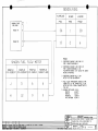
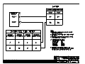
Configuring Manually (Loop-Back)
The switches that are available from the backside of the unit need to be set to the appropriate
positions as determined by the switch settings listed below. After the correct switch positions
have been selected, the unit is powered using the 'Loop-Back' harness (consult drawing number
4028-944 contained in section 11). The purpose of the 'loop back' harness is to tie the RS-232
transmit and receive ports together. This allows the software, when the unit is powered on, to read
the switch positions. Switch 1 is set to different positions to select the separate stages that the
loopback is performing. There are 5 different ‘loopback’ procedures. Use ‘loopback’ procedure 1
for Software Versions 93.00.16-93.00.29. Use ‘loopback’ procedure 2 for software versions
93.00.51-93.00.71. Use ‘loopback’ procedure 3 for software versions 93.00.77. Use 'loopback'
procedure 4 for software version 93.00.82 and above. Note that procedure 1 has 2 stages.
Procedure 2, and 3 have 4 stages and procedure 4 has 5 stages. Remember to cycle power
between stages and that the F/ADC is to be powered on for 1 minute for each stage.
The following figure shows the approximate switch positions:
Connectors
End A
End B
Switches
1
2
3
4
VIEW FROM END A
IM2820
IM2820RG.DOC, DIR. 962820
Shadin Avionics
INSTALLATION MANUAL
FUEL/AIR DATA COMPUTER
P/N 962820-1(A), 962820-2(A), 962820-3(A)
Rev: R
Loop-back Procedure 1 for Software Version 93.00.16 - 93.00.29
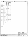
Stage 0 Loopback Configuration:
Switch 1 is set to 0 to indicate that the stage 0 loopback is being performed.
SWITCH 2
0
1
2
3
4
5
6
7
8
9
A
B
C
D
E
F
Fuel Units and Engine Type:
- Gallons
Single Engine
- Liters
"
"
- Lbs 5.8
"
"
- Lbs 6.71
"
"
- Kilograms
"
"
- Lbs 6.5
"
"
- Lbs 6.3
"
"
- (not used)
"
"
- Gallons
Twin Engine
- Liters
"
"
- Lbs 5.8
"
"
- Lbs 6.71
"
"
- Kilograms
"
"
- Lbs 6.5
"
"
- Lbs 6.3
"
"
- (DO NOT USE)
SWITCH 3
0
1
2
3
4
5
6
7
8-E
F
9600 BAUD Loran Input Type:
- Trimble
- ARNAV
- Bendix or IIMorrow Apollo NMS2001, 800, 820
- Garmin
- Northstar
- Foster
- IIMorrow 611, 612 and 618
- Shadin Flow Meter
- (DO NOT USE)
- Use this position to make selection on SWITCH 4
SWITCH 4
0
1
2
3-F
Other Loran Input Type:
- Northstar, 1200 BAUD
- Foster, 1200 BAUD
- IIMorrow 611, 612, 618; 1200 BAUD
- (DO NOT USE)
Page: 9-3
IM2820
IM2820RG.DOC, DIR. 962820
Shadin Avionics
INSTALLATION MANUAL
FUEL/AIR DATA COMPUTER
P/N 962820-1(A), 962820-2(A), 962820-3(A)
Rev: R
Stage 1 Loopback Configuration:
Switch 1 is set to 1 to indicate that the stage 1 loopback is being performed.
SWITCH 2
0
1
2
3
4
5-F
PALT Correction (static pressure correction by model):
- None
- MU-300
- Cessna Citation 501
- Cessna 525
- Cessna 550
- (DO NOT USE)
SWITCH 3
0
1
2
3
4
5
6
7-F
Loran Output Type:
- Format Z - Trimble and Garmin
- Format X - ARNAV
- Generic
- Surveyor
- Bendix C - Bendix/King and F/ADC without Baro Interface
- Bendix D - Bendix/King and F/ADC with Baro Interface
- Shadin S - IIMorrow GX50, 55, 60
- (DO NOT USE)
SWITCH 4
0
1
2
3
4
5
6
7
8-F
Altimeter Selection for Baro DC Input:
- None
(Use this selection)
- Type 1
(Not available)
- Type 2
(Not available)
- Type 3
(Not available)
- Type 4
(Not available)
- Type 5
(Not available)
- Type 6
(Not available)
- Type 7
(Not available)
- (not used)
Page: 9-4
IM2820
IM2820RG.DOC, DIR. 962820
Shadin Avionics
INSTALLATION MANUAL
FUEL/AIR DATA COMPUTER
P/N 962820-1(A), 962820-2(A), 962820-3(A)
Rev: R
Loopback Procedure 2 for Software Version 93.00.51-93.00.71
Stage 0 Loopback Configuration:
Switch 1 is set to 0 to indicate that the stage 0 loopback is being performed.
SWITCH 2
0
1
2
3
4
5
6
7
8
9
A
B
C
D
E
F
Fuel Units and Engine Type:
- Gallons
Single Engine
- Liters
"
"
- Lbs 5.8
"
"
- Lbs 6.71
"
"
- Kilograms
"
"
- Lbs 6.5
"
"
- Lbs 6.3
"
"
- (not used)
"
"
- Gallons
Twin Engine
- Liters
"
"
- Lbs 5.8
"
"
- Lbs 6.71
"
"
- Kilograms
"
"
- Lbs 6.5
"
"
- Lbs 6.3
"
"
- (DO NOT USE)
SWITCH 3
0
1
2
3
4
5
6
7
8-E
F
9600 BAUD Loran Input Type:
- Trimble
- ARNAV
- Bendix or IIMorrow Apollo NMS2001, 800, 820
- Garmin
- Northstar
- Foster
- IIMorrow 611, 612 and 618
- Shadin Flow Meter
- (DO NOT USE)
- Use this position to make selection on SWITCH 4
SWITCH 4
0
1
2
3-F
Other Loran Input Type:
- Northstar, 1200 BAUD
- Foster, 1200 BAUD
- IIMorrow 611, 612, 618; 1200 BAUD
- (DO NOT USE)
Page: 9-5
IM2820
IM2820RG.DOC, DIR. 962820
Shadin Avionics
INSTALLATION MANUAL
FUEL/AIR DATA COMPUTER
P/N 962820-1(A), 962820-2(A), 962820-3(A)
Rev: R
Stage 1 Loopback Configuration:
Switch 1 is set to 1 to indicate that the stage 1 loopback is being performed.
SWITCH 2
0
1
2
3-F
OAT Probe Type:
- Shadin OAT Probe
- ARINC 575 (DO NOT USE)
- Rosemount 500 Ω (DO NOT USE)
- (DO NOT USE)
SWITCH 3
0
1
2
3
4
5
6
7
8-F
Loran Output Type:
- Format Z - Trimble and Garmin
- Format X - ARNAV
- Generic
- Surveyor
- Bendix C - Bendix/King and F/ADC without Baro Interface
- Bendix D - Bendix/King and F/ADC with Baro Interface
- Shadin S - IIMorrow GX50, 55, 60
- Bendix B – (fuel only)
- (DO NOT USE)
SWITCH 4
0
1
2
3
4
5
6
7
8
9
A-F
Altimeter Selection for Baro DC Input:
- None
(Use this selection)
- Type 1
(Not Available)
- Type 2
(Not Available)
- Type 3
(Not Available)
- Type 4
(Not Available)
- Type 5
(Not Available)
- Type 6
(Not Available)
- Type 7
(Not Available)
- (DO NOT USE)
- Type 9
(Not Available)
- (DO NOT USE)
Page: 9-6
IM2820
IM2820RG.DOC, DIR. 962820
Shadin Avionics
INSTALLATION MANUAL
FUEL/AIR DATA COMPUTER
P/N 962820-1(A), 962820-2(A), 962820-3(A)
Rev: R
Page: 9-7
Stage 2 Loopback configuration:
Switch 1 is set to 2 to indicate that the stage 2 loopback is being performed.
SWITCH 2
0
1
Fuel Filter Type:
-
Injector
Carburetor
SWITCH 3 AND SWITCH 4
0
0
0
1
0
2
0
3
0
4
0
5
0
6
0
7
0
8
0
9
0
A
0
B
0
C
0
D
0
E
0
F
1
0
1
1
1
2
1
3
1
4
1
5
1
6
1
7
1
8
1
9
1
A-F
CORRECTION For SSEC/PSEC Select:
- No correction
- MITSUBISHI MU-300
- CESSNA CITATION 500/501
- CESSNA 525
- CESSNA 550
- Citation 560 SN <=259
- Citation 560 SN >=260
- Citation 650
- Sabreliner 65
- WestWind 1124A
- LearJet 24
- Raytheon Hawker HS 125-3A
- Falcon 20-F
- Falcon 20-C, D, E
- LearJet 25D
- Douglas DC-8
- Beechjet 400
- Boeing 707-321B
- Cessna Citation S550
- Falcon 10
- Falcon 50
- Raytheon Hawker HS125-700A
- LearJet 35
- LearJet 55
- Sabreliner 60 (SSEC Only)
- Lockheed Jetstar II
- Reserved for future (DO NOT USE)
F/ADC Software Version:
ALL
93.00.29 and up
93.00.29 and up
93.00.29 and up
93.00.29 and up
93.00.29 and up
93.00.29 and up
93.00.29 and up
93.00.29 and up
93.00.29 and up
93.00.29 and up
93.00.29 and up
93.00.29 and up
93.00.29 and up
93.00.29 and up
93.00.58 and up
93.00.63 and up
93.00.63 and up
93.00.63 and up
93.00.63 and up
93.00.63 and up
93.00.63 and up
93.00.63 and up
93.00.63 and up
93.00.63 and up
93.00.63 and up
IM2820
IM2820RG.DOC, DIR. 962820
Shadin Avionics
INSTALLATION MANUAL
FUEL/AIR DATA COMPUTER
P/N 962820-1(A), 962820-2(A), 962820-3(A)
Rev: R
Stage 3 Loopback configuration:
Switch 1 is set to 3 to indicate that the stage 3 loopback is being performed.
SWITCH 2, K-FACTOR TABLE SELECTION:
For F/ADC 962820-1(A) and 962820-2(A) only.
0
1
2-F
-
Standard K-FACTOR Matrix 0 - (Table 2 in this manual)
Alternate K-FACTOR Matrix 1- (Table 3 in this manual)
(DO NOT USE)
SWITCH 3, FUEL FLOW DELAY TIME
0
- No Delay
1
- 5 Second Delay
2
- 10 Second Delay
3
- 15 Second Delay
4
- 20 Second Delay
5
- 25 Second Delay
6
- 30 Second Delay
7
- 35 Second Delay
8
- 40 Second Delay
9
- 45 Second Delay
A-F - (DO NOT USE)
Page: 9-8
IM2820
IM2820RG.DOC, DIR. 962820
Shadin Avionics
INSTALLATION MANUAL
FUEL/AIR DATA COMPUTER
P/N 962820-1(A), 962820-2(A), 962820-3(A)
Rev: R
Loopback Procedure 3 for Software Version 93.00.77.
Stage 0 Loopback Configuration:
Switch 1 is set to 0 to indicate that the stage 0 loopback is being performed.
SWITCH 2
0
1
2
3
4
5
6
7
8
9
A
B
C
D
E
F
Fuel Units and Engine Type:
- Gallons
Single Engine
- Liters
"
"
- Lbs 5.8
"
"
- Lbs 6.71
"
"
- Kilograms
"
"
- Lbs 6.5
"
"
- Lbs 6.3
"
"
- (not used)
"
"
- Gallons
Twin Engine
- Liters
"
"
- Lbs 5.8
"
"
- Lbs 6.71
"
"
- Kilograms
"
"
- Lbs 6.5
"
"
- Lbs 6.3
"
"
- (DO NOT USE)
SWITCH 3
0
1
2
3
4
5
6
7
8-E
F
9600 BAUD Loran Input Type:
- Trimble
- ARNAV
- Bendix or IIMorrow Apollo NMS2001, 800, 820
- Garmin
- Northstar
- Foster
- IIMorrow 611, 612 and 618
- Shadin Flow Meter
- (DO NOT USE)
- Use this position to make selection on SWITCH 4
SWITCH 4
0
1
2
3-F
Other Loran Input Type:
- Northstar, 1200 BAUD
- Foster, 1200 BAUD
- IIMorrow 611, 612, 618; 1200 BAUD
- (DO NOT USE)
Page: 9-9
IM2820
IM2820RG.DOC, DIR. 962820
Shadin Avionics
INSTALLATION MANUAL
FUEL/AIR DATA COMPUTER
P/N 962820-1(A), 962820-2(A), 962820-3(A)
Rev: R
Stage 1 Loopback Configuration:
Switch 1 is set to 1 to indicate that the stage 1 loopback is being performed.
SWITCH 2
0
1
2
3-F
OAT Probe Type:
- Shadin OAT Probe
- ARINC 575 (DO NOT USE)
- Rosemount 500 Ω (DO NOT USE)
- (DO NOT USE)
SWITCH 3
0
1
2
3
4
5
6
7
8
9-F
Loran Output Type:
- Format Z - Trimble and Garmin
- Format X - ARNAV
- Generic
- Surveyor
- Bendix C - Bendix/King and F/ADC without Baro Interface
- Bendix D - Bendix/King and F/ADC with Baro Interface
- Shadin S - IIMorrow GX50, 55, 60, CNX80
- Bendix B – (fuel only)
- Garmin G
- (DO NOT USE)
SWITCH 4
0
1
2
3
4
5
6
7
8
9
A-F
Altimeter Selection for Baro DC Input:
- None
(Use this selection)
- Type 1
(Not Available)
- Type 2
(Not Available)
- Type 3
(Not Available)
- Type 4
(Not Available)
- Type 5
(Not Available)
- Type 6
(Not Available)
- Type 7
(Not Available)
- (DO NOT USE)
- Type 9
(Not Available)
- (DO NOT USE)
Page: 9-10
IM2820
IM2820RG.DOC, DIR. 962820
Shadin Avionics
INSTALLATION MANUAL
FUEL/AIR DATA COMPUTER
P/N 962820-1(A), 962820-2(A), 962820-3(A)
Rev: R
Page: 9-11
Stage 2 Loopback configuration:
Switch 1 is set to 2 to indicate that the stage 2 loopback is being performed.
SWITCH 2
0
1
Fuel Filter Type:
-
Injector
Carburetor
SWITCH 3 AND SWITCH 4
0
0
0
1
0
2
0
3
0
4
0
5
0
6
0
7
0
8
0
9
0
A
0
B
0
C
0
D
0
E
0
F
1
0
1
1
1
2
1
3
1
4
1
5
1
6
1
7
1
8
1
9
1
A-F
CORRECTION For SSEC/PSEC Select:
- No correction
- MITSUBISHI MU-300
- CESSNA CITATION 500/501
- CESSNA 525
- CESSNA 550
- Citation 560 SN <=259
- Citation 560 SN >=260
- Citation 650
- Sabreliner 65
- WestWind 1124A
- LearJet 24
- Raytheon Hawker HS 125-3A
- Falcon 20-F
- Falcon 20-C, D, E
- LearJet 25D
- Douglas DC-8
- Beechjet 400
- Boeing 707-321B
- Cessna Citation S550
- Falcon 10
- Falcon 50
- Raytheon Hawker HS125-700A
- LearJet 35
- LearJet 55
- Sabreliner 60 (SSEC Only)
- Lockheed Jetstar II
- Reserved for future (DO NOT USE)
F/ADC Software Version:
ALL
93.00.29 and up
93.00.29 and up
93.00.29 and up
93.00.29 and up
93.00.29 and up
93.00.29 and up
93.00.29 and up
93.00.29 and up
93.00.29 and up
93.00.29 and up
93.00.29 and up
93.00.29 and up
93.00.29 and up
93.00.29 and up
93.00.58 and up
93.00.63 and up
93.00.63 and up
93.00.63 and up
93.00.63 and up
93.00.63 and up
93.00.63 and up
93.00.63 and up
93.00.63 and up
93.00.63 and up
93.00.63 and up
IM2820
IM2820RG.DOC, DIR. 962820
Shadin Avionics
INSTALLATION MANUAL
FUEL/AIR DATA COMPUTER
P/N 962820-1(A), 962820-2(A), 962820-3(A)
Rev: R
Stage 3 Loopback configuration:
Switch 1 is set to 3 to indicate that the stage 3 loopback is being performed.
SWITCH 2, K-FACTOR TABLE SELECTION:
For F/ADC 962820-1(A) and 962820-2(A) only.
0
1
2-F
-
Standard K-FACTOR Matrix 0 - (Table 2 in this manual)
Alternate K-FACTOR Matrix 1- (Table 3 in this manual)
(DO NOT USE)
SWITCH 3, FUEL FLOW DELAY TIME
0
- No Delay
1
- 5 Second Delay
2
- 10 Second Delay
3
- 15 Second Delay
4
- 20 Second Delay
5
- 25 Second Delay
6
- 30 Second Delay
7
- 35 Second Delay
8
- 40 Second Delay
9
- 45 Second Delay
A-F - (DO NOT USE)
Page: 9-12
IM2820
IM2820RG.DOC, DIR. 962820
Shadin Avionics
INSTALLATION MANUAL
FUEL/AIR DATA COMPUTER
P/N 962820-1(A), 962820-2(A), 962820-3(A)
Rev: R
Loopback Procedure 4 for Software Version 93.00.82 and above
Stage 0 Loopback Configuration:
Switch 1 is set to 0 to indicate that the stage 0 loopback is being performed.
SWITCH 2
0
1
2
3
4
5
6
7
8
9
A
B
C
D
E
F
Fuel Units and Engine Type:
- Gallons
Single Engine
- Liters
"
"
- Lbs 5.8
"
"
- Lbs 6.71
"
"
- Kilograms
"
"
- Lbs 6.5
"
"
- Lbs 6.3
"
"
- (not used)
"
"
- Gallons
Twin Engine
- Liters
"
"
- Lbs 5.8
"
"
- Lbs 6.71
"
"
- Kilograms
"
"
- Lbs 6.5
"
"
- Lbs 6.3
"
"
- (DO NOT USE)
SWITCH 3
0
1
2
3
4
5
6
7
8-E
F
9600 BAUD Loran Input Type:
- Trimble
- ARNAV
- Bendix or IIMorrow Apollo NMS2001, 800, 820
- Garmin
- Northstar
- Foster
- IIMorrow 611, 612 and 618
- Shadin Flow Meter
- (DO NOT USE)
- Use this position to make selection on SWITCH 4
SWITCH 4
0
1
2
3-F
Other Loran Input Type:
- Northstar, 1200 BAUD
- Foster, 1200 BAUD
- IIMorrow 611, 612, 618; 1200 BAUD
- (DO NOT USE)
Page: 9-13
IM2820
IM2820RG.DOC, DIR. 962820
Shadin Avionics
INSTALLATION MANUAL
FUEL/AIR DATA COMPUTER
P/N 962820-1(A), 962820-2(A), 962820-3(A)
Rev: R
Stage 1 Loopback Configuration:
Switch 1 is set to 1 to indicate that the stage 1 loopback is being performed.
SWITCH 2
0
1
2
3-F
OAT Probe Type:
- Shadin OAT Probe
- ARINC 575 (DO NOT USE)
- Rosemount 500 Ω (DO NOT USE)
- (DO NOT USE)
SWITCH 3
0
1
2
3
4
5
6
7
8
9-F
Loran Output Type:
- Format Z - Trimble and Garmin
- Format X - ARNAV
- Generic
- Surveyor
- Bendix C - Bendix/King and F/ADC without Baro Interface
- Bendix D - Bendix/King and F/ADC with Baro Interface
- Shadin S - IIMorrow GX50, 55, 60
- Bendix B – (fuel only)
- Garmin G
- (DO NOT USE)
SWITCH 4
0
1
2
3
4
5
6
7
8
9
A
B
C-F
Altimeter Selection for Baro DC Input:
- None
(Use this selection)
- Type 1
(Not Available)
- Type 2
(Not Available)
- Type 3
(Not Available)
- Type 4
(Not Available)
- Type 5
(Not Available)
- Type 6
(Not Available)
- Type 7
(Not Available)
- (DO NOT USE)
- Type 9
(Not Available)
- (DO NOT USE)
- Type 11 (Not Available)
- (DO NOT USE)
Page: 9-14
IM2820
IM2820RG.DOC, DIR. 962820
Shadin Avionics
INSTALLATION MANUAL
FUEL/AIR DATA COMPUTER
P/N 962820-1(A), 962820-2(A), 962820-3(A)
Rev: R
Page: 9-15
Stage 2 Loopback configuration:
Switch 1 is set to 2 to indicate that the stage 2 loopback is being performed.
SWITCH 2
0
1
Fuel Filter Type:
-
Injector
Carburetor
SWITCH 3 AND SWITCH 4
0
0
0
1
0
2
0
3
0
4
0
5
0
6
0
7
0
8
0
9
0
A
0
B
0
C
0
D
0
E
0
F
1
0
1
1
1
2
1
3
1
4
1
5
1
6
1
7
1
8
1
9
1
A
1
B
1
C
1
D
1
E
CORRECTION For SSEC/PSEC Select:
- No correction
- MITSUBISHI MU-300
- CESSNA CITATION 500/501
- CESSNA 525
- CESSNA 550
- Citation 560 SN <=259
- Citation 560 SN >=260
- Citation 650
- Sabreliner 65
- WestWind 1124A
- LearJet 24
- Raytheon Hawker HS 125-3A
- Falcon 20-F
- Falcon 20-C, D, E
- LearJet 25D
- Douglas DC-8
- Beechjet 400
- Boeing 707-321B
- Cessna Citation S550
- Falcon 10
- Falcon 50
- Raytheon Hawker HS125-700A
- LearJet 35
- LearJet 55
- Sabreliner 60 (SSEC Only)
- Lockheed Jetstar II
- Antonov (AN 12)
- Antonov (AN 24)
- Antonov (AN 26)
- Antonov (AN 30)
- Yakovlev (YAK 40)
F/ADC Software Version:
ALL
93.00.29 and up
93.00.29 and up
93.00.29 and up
93.00.29 and up
93.00.29 and up
93.00.29 and up
93.00.29 and up
93.00.29 and up
93.00.29 and up
93.00.29 and up
93.00.29 and up
93.00.29 and up
93.00.29 and up
93.00.29 and up
93.00.58 and up
93.00.63 and up
93.00.63 and up
93.00.63 and up
93.00.63 and up
93.00.63 and up
93.00.63 and up
93.00.63 and up
93.00.63 and up
93.00.63 and up
93.00.63 and up
93.00.85 and up
93.00.85 and up
93.00.85 and up
93.00.85 and up
93.00.85 and up
IM2820
IM2820RG.DOC, DIR. 962820
Shadin Avionics
INSTALLATION MANUAL
FUEL/AIR DATA COMPUTER
P/N 962820-1(A), 962820-2(A), 962820-3(A)
Rev: R
Stage 3 Loopback configuration:
Switch 1 is set to 3 to indicate that the stage 3 loopback is being performed.
SWITCH 2, K-FACTOR TABLE SELECTION:
For F/ADC 962820-1(A) and 962820-2(A) only.
0
1
2-F
-
Standard K-FACTOR Matrix 0 - (Table 2 in this manual)
Alternate K-FACTOR Matrix 1- (Table 3 in this manual)
(DO NOT USE)
SWITCH 3, FUEL FLOW DELAY TIME
0
- No Delay
1
- 5 Second Delay
2
- 10 Second Delay
3
- 15 Second Delay
4
- 20 Second Delay
5
- 25 Second Delay
6
- 30 Second Delay
7
- 35 Second Delay
8
- 40 Second Delay
9
- 45 Second Delay
A-F - (DO NOT USE)
Page: 9-16
IM2820
IM2820RG.DOC, DIR. 962820
Shadin Avionics
INSTALLATION MANUAL
FUEL/AIR DATA COMPUTER
P/N 962820-1(A), 962820-2(A), 962820-3(A)
Rev: R
Page: 9-17
Stage 4 Loopback configuration:
Switch 1 is set to 4 to indicate that the stage 4 loopback is being performed. Refer to the OAT probe
calibration certificate for the Ta, Tb, Tc calibration code selection.
SWITCH 2, OAT Ta CALIBRATION CODE SELECTION:
0-F
-
Refer to calibration certificate for “A” code selection 0 to F.
SWITCH 3, OAT Tb CALIBRATION CODE SELECTION
0-F
-
Refer to calibration certificate for “B” code selection 0 to F.
SWITCH 4, OAT Tc CALIBRATION CODE SELECTION
0-F
-
Refer to calibration certificate for “C” code selection 0 to F.
Note: Switch 2, 3, and 4 are set to position 0 (zero), if the OAT probe does not have a calibration code
marking, (i.e. A=0, B=0, C=0).
IM2820
IM2820RG.DOC, DIR. 962820
Shadin Avionics
INSTALLATION MANUAL
FUEL/AIR DATA COMPUTER
Rev: R
P/N 962820-1(A), 962820-2(A), 962820-3(A)
Page: 9-18
SELECT NO DELAY
Only under special circumstances should a fuel flow delay time other than “No Delay” be
selected. Read the following paragraphs for a description of these special circumstances.
On a few aircraft installations which have digital fuel flow and use a very low K factor (858 pulses
per gallon), there has been a problem with the Air data reporting a large jump in fuel used as well
as a corresponding decrease in fuel remaining at engine startup. This is not considered to be a
Shadin Air data problem, but rather has been defined as an aircraft problem involving noise on the
digital fuel flow signal.
A solution for this problem is to use the Air data fuel flow delay feature. This feature suppresses
the fuel flow (and its affect on fuel used and remaining) for a startup delay time each time the
engine starts. Fuel flow delay time is selectable in the Air data loopback mode, with selections of
0, 5, 10, 15, 20, 25, 30, 35, 40, and 45 seconds delay available.
If a fuel flow delay is needed, start by reconfiguring the ADC to use a large delay (i.e. 45
seconds). If the large fuel flow mitigated the problem, try reducing the delay until the problem
returns. Then use the least amount of fuel flow delay that suppresses the problem.
When a fuel flow delay time is selected the Air data checks for fuel flow below 15 pph. If the fuel
flow is below 15 pph, the Air data considers the engine to be off and returns a fuel flow of 0.
Then as soon as the fuel flow exceeds 15 pph, the Air data continues to return a fuel flow of 0
until the delay time has expired. In a twin engine, the Air data zeroes both fuel flows during the
startup delay for each engine.
SPECIAL OPTIONS
Only under special circumstance should SPECIAL OPTION 1 be selected. Read the following
paragraphs for a description of the special circumstance.
Because the IAS range on the Air data computer is valid from 20 to 350 knots ARINC 429 labels
206 and 210 are transmitted with NCD status and stop being transmitted almost simultaneously if
the IAS is less than 20 knots. In order to interface with certain avionics equipment which exhibit
warnings if a valid IAS or TAS label is not received, SPECIAL OPTION 1 was implemented.
When the Air data computer is configured with SPECIAL OPTION 1 the Arinc 429 labels 206
and 210 are transmitted with OK status and a value of zero knots if the actual IAS is less than 20
knots.
IM2820
IM2820RG.DOC, DIR. 962820
Shadin Avionics
INSTALLATION MANUAL
FUEL/AIR DATA COMPUTER
P/N 962820-1(A), 962820-2(A), 962820-3(A)
Rev: R
10.0
Page: 10-1
SETTING THE K FACTOR
The process of setting the K Factor is needed to match the F/ADC to the aircraft fuel flow system
characteristics. To set the K Factor into the F/ADC you must first determine whether it is an
Analog, Digital or Sine Fuel Flow unit.
P/N
962820-1(A)
962820-2(A)
962820-3(A)
FUEL FLOW TYPE
Digital
Sine Wave
Analog
Use the switch settings from the appropriate table to set the K Factor.
For Digital or Sine units (P/N (s) 962820-1(A) and -2(A)) use the Digital K Factor Settings
Tables.
Switch 1 & 2 selects the left K Factor
Switch 3 & 4 selects the right K Factor
Due to possible fuel flow system peculiarities, switch 1 & 2 and switch 3 & 4 do not necessarily
need to be set to the same setting. For a one engine system, use switches 1 & 2.
For Analog units (P/N 962820-3(A)) use the Analog K Factor Settings Table.
Switch 1 & 2 selects the main engine K Factor
Switch 3 & 4 selects the offset.
The offset is simply the value represented by switches 3 & 4 in the Analog K Factor Settings
Table below. For example, if you wanted an offset of 0, the switch settings would be 0,0. If you
wanted an offset of 416, the switch settings would be 0, 1. If you wanted an offset of 1094, the
switch settings would be 0, 4.
Configuration is now complete.
IM2820
IM2820RG.DOC, DIR. 962820
Shadin Avionics
INSTALLATION MANUAL
FUEL/AIR DATA COMPUTER
P/N 962820-1(A), 962820-2(A), 962820-3(A)
Rev: R
Page: 10-2
Analog K Factor Settings Table
Manufacturer
Beech
Beech
Beech
Beech
Beech
Beech
Beech
Beech
Beech
Beech
Beech
Cessna
Cessna
Cessna
Cessna
Cessna
Piper
Piper
LearJet
LearJet
LearJet
Boeing
British Aero
British Aero
British Aero
Canadian
Canadian
Dornier
Daussault
Daussault
Daussault
Swearngen
Gulfstream
Gulfstream
Aerospatiale
DHC
IAI
IAI
Sikorsky
Sikorsky
Sabre
Standalone Air data MKII Analog Fuel Flow Chart
Model
SW1 SW2 SW3
SW4
K-Factor
KingAir B200
0
0
0
1
77000
KingAir A100
0
1
0
2
26150
KingAir C90
0
1
0
2
26150
KingAir F90
0
0
0
1
77000
KingAir C90A
0
0
0
1
77000
KingAir 200
0
0
0
1
77000
BeechJet
0
2
0
0
11540
KingAir B100
0
3
0
2
26150
Beech 600
0
4
0
0
38460
Beech 750
0
5
0
0
30770
Beech 800
0
6
0
0
28850
Citation, Ametek
0
C
0
0
16270
Gauge 02C208E
Citation, Simmons
1
C
0
0
14300
Gauge 393002-009
Citation II/SII
0
C
0
0
16270
Citation III
0
D
0
4
9620
Model 525
0
E
0
0
21980
Cheyenne III
1
9
0
0
41960
Cheyenne IV
1
1
0
0
46150
LearJet
0
7
0
0
15380
Model 36 (5V)
0
2
0
0
11540
Model 36 (10V)
0
8
0
0
23080
Boeing-737-300
0
9
0
3
1790
BAE ATP
0
7
0
0
15380
BAE-125-800
0
A
0
0
8240
HS-125
0
B
0
0
10490
CL600
0
F
0
0
6590
CL601
1
0
0
0
5130
DO-228
1
1
0
0
46150
FALCON 10
0
2
0
0
11540
FALCON 20
1
2
0
0
7690
TFE-371
1
2
0
0
7690
MERLIN
0
4
0
0
38460
GULFSTREAM II
1
3
0
0
2880
GULFSTREAM
1
4
0
0
2310
III
PUMA
1
5
0
0
76920
DHC DASH 8
1
6
0
0
19230
ASTRA 1125
1
7
0
5
9230
WESTWIND 1124
1
8
0
0
10490
S-76A
1
1
0
0
46150
S-76B
0
6
0
0
28850
SABRE 65
1
7
0
5
9230
Table 1
Offset
416
875
875
416
416
416
0
875
0
0
0
0
0
0
1094
0
0
0
0
0
0
0
0
378
0
0
0
0
0
0
0
0
0
0
0
0
2188
0
0
0
2188
IM2820
IM2820RG.DOC, DIR. 962820
Shadin Avionics
INSTALLATION MANUAL
FUEL/AIR DATA COMPUTER
P/N 962820-1(A), 962820-2(A), 962820-3(A)
Rev: R
Page: 10-3
Matrix 0 - Digital K Factor Settings
PPG
SW1
SW2
PPG
SW1
SW2
PPG
SW1
SW2
860
5000
5050
5100
5150
5200
5250
5300
5600
5650
5700
5750
5800
5850
5900
5950
6000
6380
6400
6420
6440
6460
6480
6500
6520
6540
6560
6580
6660
7640
D
6
6
6
6
6
7
7
6
6
6
6
6
6
6
6
6
C
C
C
C
C
D
D
D
D
D
D
6
5
D
B
C
D
E
F
0
1
0
1
2
3
4
5
6
7
8
B
C
D
E
F
0
1
2
3
4
5
A
9
8800
9000
9200
9400
9600
9800
10000
10100
10200
10300
10400
10500
10600
10700
10800
10900
11000
11100
11200
11300
11400
11500
14500
14600
14700
14800
14900
15000
15100
15200
5
5
5
5
5
5
5
5
5
5
5
5
5
5
5
D
D
D
D
D
D
D
D
D
E
E
E
E
E
E
0
1
2
3
4
5
6
7
8
A
B
C
D
E
F
6
7
8
9
A
B
C
E
F
9
A
B
C
D
E
15300
18000
18200
18400
18600
18800
19000
19200
19400
19600
19800
20000
20200
20400
20600
20800
21000
21200
21400
21600
21800
22000
22200
22400
22600
22800
23000
23200
23400
23600
E
3
3
2
3
3
3
3
3
3
3
3
3
3
3
3
3
4
4
4
4
4
4
4
4
4
4
4
4
4
F
0
1
2
3
4
5
6
7
8
9
A
B
C
D
E
F
0
1
2
3
4
5
6
7
8
9
A
B
C
Table 2
IM2820
IM2820RG.DOC, DIR. 962820
Shadin Avionics
INSTALLATION MANUAL
FUEL/AIR DATA COMPUTER
P/N 962820-1(A), 962820-2(A), 962820-3(A)
Rev: R
Page: 10-4
Matrix 0 - Digital K Factor Settings
(Continued)
PPG
SW1
SW2
PPG
SW1
SW2
PPG
SW1
SW2
23800
24000
24200
24400
24600
24800
25000
25200
25400
25600
25800
26000
26200
26400
26600
26800
27000
27200
27400
27600
27800
28000
28200
28400
28600
28800
29000
29200
29400
29600
4
4
4
B
B
B
B
B
B
C
C
C
C
C
C
C
C
C
C
F
F
F
F
F
F
F
F
F
F
F
D
E
F
A
B
C
D
E
F
0
1
2
4
5
6
7
8
9
A
0
1
2
3
4
5
6
7
8
9
A
29800
30000
30200
30400
33800
37000
37200
37400
37600
37800
38000
38100
38200
38300
38400
38500
38600
38700
38800
38900
39000
39100
39200
39300
39400
39500
39600
39700
39800
39900
F
F
F
F
6
B
B
B
B
B
8
8
8
8
8
8
8
8
8
8
8
8
8
8
8
8
9
9
9
9
B
C
D
E
9
9
8
7
6
5
0
1
2
3
4
5
6
7
8
9
A
B
C
D
E
F
0
1
2
3
40000
40200
40400
40600
40800
41000
41200
41400
41600
41800
42000
42200
42400
42600
42800
43000
43200
43400
43600
43800
44000
44200
44400
44600
44800
45000
45200
45400
45600
45800
9
9
9
9
9
9
9
1
1
1
1
1
1
1
1
1
1
1
1
1
1
1
1
2
2
2
2
2
2
2
4
5
6
7
D
E
F
0
1
2
3
4
5
6
7
8
9
A
B
C
D
E
F
0
1
2
3
4
5
6
Table 2 continued
IM2820
IM2820RG.DOC, DIR. 962820
Shadin Avionics
INSTALLATION MANUAL
FUEL/AIR DATA COMPUTER
P/N 962820-1(A), 962820-2(A), 962820-3(A)
Rev: R
Page: 10-5
Matrix 0 - Digital K Factor Settings
(Continued)
PPG
SW1
SW2
PPG
SW1
SW2
PPG
SW1
SW2
46000
46200
46400
46600
46800
47000
47200
47400
47600
49000
49100
49200
49300
49400
49500
49700
50000
50200
50400
50500
50800
55500
55550
57000
57100
57200
57300
57400
57500
57600
2
2
2
2
2
2
2
2
2
9
9
9
9
9
E
E
E
E
E
E
E
C
F
A
A
A
A
A
A
A
7
8
9
A
B
C
D
E
F
8
9
A
B
C
2
3
4
5
6
7
8
3
F
0
1
2
3
4
5
6
57700
57800
57900
58000
58100
58200
58300
58400
58500
58600
58700
58800
58900
60000
77000
78000
79000
80000
81000
82000
83000
84000
85000
86000
87000
88000
89000
90000
91000
92000
A
A
A
A
A
A
A
A
A
B
B
B
B
B
0
0
0
0
0
0
0
0
0
0
0
0
0
0
0
0
7
8
9
A
B
C
D
E
F
0
1
2
3
4
0
1
2
3
4
5
6
7
8
9
A
B
C
D
E
F
93000
94000
95000
96000
97000
98000
99000
100000
101000
102000
103000
104000
105000
106000
7
7
7
7
7
7
7
7
7
7
7
7
7
7
2
3
4
5
6
7
8
9
A
B
C
D
E
F
Table 2 continued
IM2820
IM2820RG.DOC, DIR. 962820
Shadin Avionics
INSTALLATION MANUAL
FUEL/AIR DATA COMPUTER
P/N 962820-1(A), 962820-2(A), 962820-3(A)
Rev: R
Page: 10-6
Matrix 1 - Alternate Digital K-Factor Setting Table (software version 93.00.61+)
PPG
SW1
SW2
PPG
SW1
SW2
PPG
SW1
SW2
200
400
440
490
510
520
530
540
550
560
570
580
590
600
610
620
630
640
650
660
670
680
690
700
710
720
730
740
750
760
770
780
790
800
810
820
840
850
880
900
1000
1200
1400
1600
1800
1
1
1
1
1
1
1
1
1
1
1
1
1
1
1
1
2
2
2
2
2
2
2
2
2
2
2
2
2
2
2
2
3
3
3
3
3
3
3
3
3
3
3
3
3
0
1
2
3
4
5
6
7
8
9
A
B
C
D
E
F
0
1
2
3
4
5
6
7
8
9
A
B
C
D
E
F
0
1
2
3
4
5
6
7
8
9
A
B
C
1940
2000
2200
2400
2600
2800
3000
3200
3400
3600
3610
3650
3690
3730
3760
3800
3800
3840
3880
3920
3960
4000
4000
4040
4080
4120
4160
4200
4200
4400
4700
11700
11900
12100
12400
12600
12800
13000
13500
14000
14200
14400
15500
15700
15900
8
3
3
3
4
4
4
4
4
4
0
0
0
0
0
0
4
0
0
0
0
0
4
0
0
0
0
0
4
4
4
5
5
5
5
5
5
5
5
6
6
6
4
4
4
0
D
E
F
0
1
2
3
4
5
0
1
2
3
4
5
6
6
7
8
9
A
7
B
C
D
E
F
8
9
A
8
9
A
B
C
D
E
F
0
1
2
B
C
D
16100
16300
16500
16600
16800
17000
17200
17400
17600
17800
30600
30800
31000
31200
31400
31600
31800
32000
32200
32400
32600
32800
33000
33200
33400
33600
34000
34200
34400
34600
34800
35000
35200
35400
35600
35800
36000
36400
36800
4
4
5
5
5
5
5
5
5
5
6
6
6
6
6
6
6
6
6
6
6
6
6
7
7
7
7
7
7
7
7
7
7
7
7
7
7
7
7
E
F
0
1
2
3
4
5
6
7
3
4
5
6
7
8
9
A
B
C
D
E
F
0
1
2
3
4
5
6
7
8
9
A
B
C
D
E
F
Table 3
IM2820
IM2820RG.DOC, DIR. 962820
Shadin Avionics
INSTALLATION MANUAL
FUEL/AIR DATA COMPUTER
P/N 962820-1(A), 962820-2(A), 962820-3(A)
SECTION 11.0
INSTALLATION DRAWINGS AND
INSTALL KIT PARTS LISTS
. . ."
---------
---.;........
-
NOTES:
1. REFERENCE PIN 681201-1 OAT PROBE
ASSEMBL Y KIT
2. AVOID INSTALLING OAT PROBE
IN OR NEAR:
PROP AIRSTREAM
ENGINE EXHA0sT FLD~ PATH
CABIN HEATERS EXHAUST FLo~ PATH
TRANSMITTING ANTENNAS <DME, TXP, COMMJ
DARK PAINTED A~EAS
&
OA T PROBe PIN 681201
&.
TORQUE NUT, FN 25, TO 1.3 IN-LBS (MAX)
DRILL
O.098¢
,- @&
AIRCRAFT FUSELAGE
(#40) 4 PL.
DRILL
O.359¢
(23/64")
30
0.50
o
f 1.0'0
DETAIL A
MOUNTING HOLE DETAIL
~~~:~1H~~I~~ ~~r:s
SHA.DfN
HINN£AP(LJS. MN
S5~
INST ALLATIDN
~iLI:~~~~~~~~~~~~~==========1F'iRI~7."':'N/A:-----D~---1DA T PROBE ASSEM.BL Y KIT
TOLERANCES'
MATERIAL.
...fA
±o.Ol·
J
»RAVING. rtl.
4028-005
SIZE
A
PIN' 681201 1
-
R£V
C
,
'.
'.
I
l ..
,_.,
_ ...
_LtST OF
_M~TE~IAL
."j
I
¢.15 (x4)
/1-'
/.~~J
~G5+1
·tLtl
\,,+0"/
\\+' /
'-~
'-~
oQ
/1
3,10
2.00
'1-~
tL+ '\
\-, 0~j
IL~l,
\,'y/ /
'
\
,
,
~
J
/
/
/1
1
I
.
/
I
.55
1,55
3.25
6.35
?
.20
~ ¢85~
MOUNTING HARDWARE REQUIRED:
(AN526-632-8) SCREWS
(AN960-6) LOCKWASHERS
(AN364-6"32) NUTS
~
0.50
.16
------1..
.;;T
~
QTY
4
4
UNLESS OTHERWISE NOTED
DIt.4ENSlONS ARE IN INCHES
TOLERANCES: X.X - ±O.1
4
X~_±±~!64/X~~:::
h"'L VLV I 0
19902/0201 A
I
1
I ,u.. ..J/"" I LJM
KCL 1AODED P7N TO TITLE BLOCK
1 3/2/99 1 CMG 1 PG IUPDATED TRAY USED
I .- ,.- ,_.
,FlNISH:
It.4A
IA
DAP I SES IBASEUNE RELEASE
BY :lAPPD]
DESCRIPTION
I
I
-.1.30
CAD FILE AVAIL:
YES
I
TER L:
:g:g65
N/A
N/A
SCALE: 1 : 1
ORAWlI;l.GDATt:
10/12/94
I~
APPRO~D
FlLESENSAME
S"'2801A8J.DWG
D1RE§I~~J1A
SHEET
10F 1
C'LT'A'
nrw
A.J~-' L/.LJ
t.41NNEAPOUS. MN
554-26
INSTALLATION,
MOU N TI NG TR AY
DRAWINC NO.
I SIZE I /
4028- 411 ,
A
,P N 542801' A.
I
REV
.8
e
'-e
NOTES
&
•
USE RS-232 OR RS-422, BUT NOT BOTH.
2.
ALL DIMENSIONS ARE REFERENCE ONLY.
Jl
1.
2.
3.
4.
S.
PINDUT
F"UEL F"LDIJ, RIGHT - POIJER
ruEL F"LDIJ, RIGHT - SIGNAL
F"urL F"LOIJ RIGHT - GROUND
HEADING Y
HEADING X
6. 26V400Hz, H
7. 26V 400Hz, Z, C
9.
9.
10.
U.
12.
13.
14.
15.
NC
F"UEL F"LOIJ, LEFT - POIJER
rUEL F"LDIJ, LEn - SIGNAL
rUEL F"LO'J LEH - GROUND
3.280
NC
NC
OAT
OAT
+
(SIgnal)
(+5V)
@
@
J2 PINOUT
1. 12 - 28v DC POIJER INPUT
2.
l'
~
l'
~
3.
{4.
S.
6.
7.
8.
9.
10.
{11.
12.
13..
14.
IS.
NC
RX+, RS-422
RX-, RS-422
RX, RS-232
TX, RS-232
0563l ~
NC
2.000
3.125
------i
0.125
I
6.250
NC
GROUND
HC
l'X+, RS-422
TX-, RS-422
MATING CONNECTORS'
P2
-NC
230050 - CONN, SHELL, FEMALE
.230055. - CONN, PINS, FEMALE
230038 - CONN, HOOD, 15 PIN
SIGNAL GND
NC
P1
230051 - CONN, SHELL, MALE
230054 - CONN, PINS, MALE
230038 - CONN, HOOD, 15 PIN
SHA.DIlV.
HINN(AP(1.IS. HN
s:l426
INSTALLATION) ADC200
BASELINE RELEASE
DESCRIPTIDN
FREQ/LEVEL INT FF
I I
962820-1
DRA\lING NO.
4028-604
SIZE
A
P/ N
REV
.-.~-----
,
NOTES
&.
USE RS-232 DR RS-422, BUT NOT BOTH.
2.
•
-------
ALL DIMENSIONS ARE REFERENCE ONLY.
Jl
1.
2.
3.
4.
5.
6.
7.
9.
9.
10.
PINOUT
FUEL FLO"', RIGHT - (-)
FUEL FLO"', RIGHT - (+)
FUEL FLO'" RIGHT - GROUND
HEADING Y
HEADING X
26V 400Hz, H
26V 400Hz, Z, C
HC
11.
FUEL FLO"', LEF"T - (-)
FUEL FLO"', LEF"T - (+)
FUEL FLO'" LEF"T - GROUND
12.
13.
14.
15.
HC
NC
OAT
OAT
+
3.280
(Signal)
(+5V)
®
'i'
~
•.
J2 PINOUT
1. 12 - 28v DC P[]'JER INPUT
2. NC
3. RX+, RS-422
{4.
S.
6.
7.
9.
9.
10.
If {11.
~ 12.
13.
14.
IS.
RX-, RS-422
RX, RS-232
TX, RS-232
HC
NC
GROUND
NC
TX+, RS-422
TX-, RS-422
Ne
SIGNAL GND
HC
0.563
-IT-
2.000
3.125
----=i~
I
~ 1375
1-
I
@
0.125
3.250
6.250
•I
MATING CONNECTORSI
P2
230050 - CONN, SHELL. FEMALE
230055 - CONN, PINS, FEMALE
230038 - CONN, HOOD. 15 PIN
PI
230051 - CONN, SHELL MALE
230054 - CONN, PINS, MALE
230038 - CONN, HOOD. 15 PIN
SHAPIN
BASELINE RELEASE
DESCRIPTION
MINNEAPOLIS. HN
55426
INSTALLATION) ADC200
SINE'WAVE FF
REV
DRA"'ING NO.
ISIZE I
962820-2
4028.-605
A
PIN
NOTES
&.
2.
•
•
USE RS-232 OR RS-422 1 BUT NOT BOTH.
•
ALL DIMENSIONS ARE REFERENCE ONLY,
Jl PINDUT
1. rUEL n.D1J. RIGHT - (-)
2. F'UEL rLDIJ,RIGHT - (+)
3. F'UEL rLDIJ RIGHT - GRDUND
4. HEADING Y
5. HEADING X
6. 26V 400Hz. H
7. 26V 400Hz. Z, C
8. NC
9. rUEL rLDIJ; LErT - (-)
10. rUEL rLDIJ. LEn - (...)
U. rUEL rLDIJ LEn - GROUND
12. NC
13. Nt
14. DAT - (Signal>
·15. DAT ... (+5V>
3,280
®
J2 PINDUT
1. 12 - 28v DC PDIJER INPUT
2. NC
3. RX+. RS-422
{4. RX-, RS-422
~ S. RX, RS-232
6. TX, RS-232
7. NC
8. NC
9. GROUND
10. NC
{11. TX+. RS-422
~ 12. TX-, RS-422
13. NC
14. SIGNAL GND
lS. NC
l'
O.
S63
l ~ =D
3.125
l'
0.125
-I
2.000
6.250
MATING CONNECTORS.
P2
230050 - CONN. SHELL, FEMALE
230055 - CONN. PINS. FEMALE
230038 - CONN. HOOD. 15 PIN
PI
230051 - CONN, SHELL, MALE
230054 .- CONN. PINS. MALE
230038 - CONN. HOOD. 15 PIN
SHA.DIlV
MlNNEAP{LIS. HN
:s:l4Z6
INSTALLATION) ADC200
BASELINE RELEASE
DESCRIPTION
DRAIJING NO.
4028-606
I
DC
SIZE
A
FF
IP IN
962820-3
REV
·._.
. •
ADC200
•
962810-X
962820-X
Jl
SPLICE
[
OAT
PD\JE~
1\
f\
lSi
\
SIGNAL 1 14 I
1
COMPASS
HEADING
Y
I 4
x
5
26V 400Hz
H
6
~
\JHT or BLK
ZIC I 7
GND I 11
SHADIlV
HINN[AP(LIS. HN
SS426
INSTALLATION \JIRING, FUEL AIRDATA
COMPUTER (ADC200) TO OAT/HEADING
SYSTEM
.
DRAW'ING NO.
4028~607
I A Ip / N
SIZE
IREV
A
•
..-...;.._------~~-
LEVa
rr
INTIRF"ACE
fREQUENCY FT INTERF"AC£
962910-1
96Z820-1
Jl
D.C. fUEL F"lO.... [J'TIDN
[PTI~
962910-3
962921)-3
96Z8lD-l
962820-1
.------- •
Jl
JI
'
[P~
0::
GROUND 13 h
GRtUlD 13Q
5
$181
2
RIGHT
F'UEL
)
F"LD\I
SIGNAl. F"RDH
EXISTlNG SYSTEM
nn.
~181
-SIG
+SIG
He
sro'+i'
~
RI~T
F"LD\I
LEn
LETT
2
12
-SIG
'3
+SIG
10
He
It
nn.
fLO\I
5 TO 10V DC
F"CR F1.U. SCALE
CHDDEl. DEPENDANT>
F"IJEL
F"LD\I
'~T
2
liND
3
"~I
~I
to
SIG
10
GND
It
68O:lOl-X
C
6605XX
[R
'
'
.SIG
m_aaR
SHADIN
PIN
B
~r~
f\
SHADIN PIN
B
~-X
[R
~
V
~X
"r
IZ
He
LEVEl. FT INTERrACE [PTIaf
SINE fUEL fLDV [PTIDN
962910-2
96282G-2
Jl
It ENGINE
HAGNES(N fF.
F"REQUENCY IT Itm:RF"ACE [PTIDN
962810-1
962820-1
TO F"RElt CONERTER
PIN 930503
[=4~
Jl
~;:~:~
~
ITt
OJ
- SIG
1
F"UEL
F"LOW'
+ SIG
2
GHD
3
- SIG
9
96Z810-1
962820-2
LEn
fUEl
F"LO....
• SIG
10
GHD
11
SINE
\lAVE
Jl
n.n
F1...DV
PICKUPS
.RIGHT
+15V
F"IJEL
F"LOW'
SIG
GND
u:n
lIZ R. F'REQ. f F. WT
"-I
./
RI~T
L F"REQ. fF. WT
13 GROOND
SINE
\lAVE
F1JEL
F"LD\I
PICKUPS
F'UEI..
fLOW'
1
3
+15'1
9
SIG
10
GND
11
IDRA'w'l/olG DATE
1216/'34
DRArTER 'WMP .
I
I
I
A
I
9/13/95
I
'w'HP
I
SES
I CORRECT
PIN ON LEVEL ff INTERfACE OPTION
9506/011
BASELINE RELEASr-
ECO"
DESCRIPTION
nTW
HINNEAPll.lS. HN
55426
INSTALLA nON 'WIRING, FUELI AIRDA TA
APPROV<>
9509/015
C"LTA
AJ~a.v.L.i
1~~~~:~;~J.D'WGr_ ----;:C~0:7M:::P::U:-:::T:-E-R-(...,ArD-C-2"T"""0-O-) _T_O_F_U_E_L_ _S_Y_S_T_E_M--.J
•
-.
DRA'WING NO.
4028-608
I
SIZE
A
(p/ N
{REV
A
•
•
·CNX
GARMIN
80
430, 530
BENDIX/
BENDIX/
KING
KING
KLN90
KLN90B
962810"X}
962820-X
962830-X
X
= 1,
KLN89
2, 3
'
GARMIN
150, 155,
155XL,
165,
250, 250XL
300, 300XL
•
LNS
BENDIX/
6000
KING
roSTER
7000
IIMORRO'w'
IIMORRO'w'
IIMORRO'w'
IIMORRO'w'
ARNAV
MAGELLAN
360
NHS2001
820
GX 50,
FHS7000,
SKYNAV
60
R5000
STAR5000
5000
KLN 900
J2
RS-232
RX
RS-232
TX
"
/-\
5
I
I
I
I
I
\
\
6
\
\
\
,
,,
TX
TX
TX
TX
TX
TX
TX
TX
TX
22
56
13
2
24
25
6
A
8/1
RX
RX
RX
RX
RX
RX
RX
RX
RX
21
57
36
1
17
26
38
R
20/14
TX
(SOFTIJARE
SELECT>
19/37
A
B
IIHORRO'w'
GX 55
TX
TX
TX
TX
TX
TX
6
5
3
12
25
6
RX
RX
RX
RX
RX
RX
7
4
4
11
23
7
I
I
,
:
I
RX
21/38
'/
I..-
l
l-J
I DR~~~~J'8A TE
IllJo(AJ'gl~~R
0501/006
0211/047
0009/006
9803/025
ECD.
C.
B
A
-
REV.
IN:'-ID~
2/7/03·
9/6/00
3/26/98
DATE
PAB
PAB
PAB
SRB
BY
AJK.
BAL
EDJ
.KCL
APP'D
ADDED CNX 80
DEL PIN 9) ADDED GND
ADD GARHIN 430/530 GPS
BASELINE RELEASE
DESCRIPTION
NOT TO SCALE
APPROVED
PAB
rILE NAME
402B-943CJ.DIJG
DIRECTORY
4029
SHEET 1 OF 1
SHAPIN
HlNNEAPO...IS MN
55<426
INSTALLATION "'IRING, F IADe-200, 2000
TO NAV RECEIVERS
DRAIJING NO.
4028-943
I
SIZE
A
~/RS-232
fP/
N
c.
(REV
•
-
•
J2
+28VDC
1\
1
GND
9
RX RS232
5
TX RS232
6
j
j
~
--
~
llilIES!.
1. C'ONSUL T INSTALL AnON MANUAL FOR
F / ADC PROGRAMMING INSTRUCTIONS.
2. MA TING CONNECTOR; 15 PIN FEMALE
D-SUB (SHADIN PN 230050C) OR EQUIVALENT
"
DR'1'"j~S~9D8A TE
SHA.DIlV
.~
0501/032
B'
q J NJOIi
2J'14/05
CJ809/022
9803/025
-
A
9/281198
DLR
3....;26~98
SRB
E:Cll •
I REV.
0509/028
'C
' DArE
PAB
PAD
BY
'J.j/I\.
CORRECTED PIN OUT J2'S
UPDATED TITLE BLOCK
CORRECTED PIN OUT
KCL BASELINE RELEASE
. i)ESCRIPT N
APP'D
a.
APPROVED
KCL
rILE NAME
4029-944CJ.D\lG
DIRECTORY
6/ EDITED NOTE 2
\IMP
KCL
4029
NOT TO SCALE
ISHEET
nF" 1
HIN€ A PtLlS.
HN
:550426
INSTALLATION "'IRING, LOOP
BACK HARNESS FOR F IADC200, 2000, D-SUB
CONNECTOR
'
~A'JIN(j
NO.
4028-944
, SIZE'
'"
P/ N
C
'R
..•
962810-X}
X = 1, 2, 3'
962820-X
962830-X
TRIMBLE
TRIMBLE
NORTSTAR
1000,
2100,
MIA
2000,
2101.
3000
3100
M2
M3
••
•
60/600
J2
1"\
/
RS-422
TX, SDA+
11
I
I
I
I
I
I
I
I
/-,
RX, SDA+
\
"
I
I
I
I
I
I
I
,
I
,
\
I
'I.
\
\
I
/
3
7I "
\I
,
TX, SDA+
TX, SDA+
TX, SDA+
15
37
11
TX, SDB
TX, SDB
TX, SDB
3
5
6
I
I
I
I
I
,
I
I
I
I
:
I
4
8
"
.
\
I
RX, SDB
4
J
\
SDB~
N/A
I
I
I
I
I
I
I
I
I
I
RS-422
R, SDB
RX,
I
\
RS-422
RX, SDA+
7
16
I
I
12
N/A
I
I
I
RS-422
TX, SDB
RX, SDA+
'.
"
\
\
,T /
I
I
I
I
I
'-l
U
DRA'Wt~
_UATE
'fiR~12~98
APPROVED
KCL
FILE NAME
0211/047
98tl3/025
I"CD ..
A
-
REV.
3/11/03
PAD
DAL
3/26/98
SRB
BY
KCL' BASELINE RELEASE
n4TE
APP'D
4028-946AJ,D'w'G
DEL PIN 9, ADDED GND
DESCRIPTION
SHA.lJIlV
DIRECTORY
DRA'WING NC.
4028
NO
seA _E
,<:\·U'-F
rll"
MtNNEAf'[JJs.
K'l
55-426
INSTALLATION \JIRING, F/ADC200, 2000
TO NAV RECEIVERS 'vI/RS-422, RS-485
4028-946
I IP / N
SIZE
A
IRA
.
,
.
.
_.. .
KLN90 J A J B
SHADIN F IADC
200 1 2000
J2
1\
RS232 TX
6
RS232 RX
5
1 - 1. . .-
P901
(
-
-
-
-
-
-
-
-
-
-
-
-
-
-
-
-
-
-
-
-
-
-
,
.
BENDIX/KING
r
_
KLN89
KLN900
P891
P9002
36
1
38
13
2
6
L..J
.till.I.E..S!
1. CONFIGURE SHADIN F I ADC 200 110
SHA·DIN 'FUEL FLDV METER
FOR FLoW'METER/BENDIX C.
2. CONFIGURE SHADIN F I ADC 2000 110
DIGIFLO
PIN 91053XT
I PINDIGIFLO
I MINIFLO
91053XP PIN 91204X
MICROFLO
91204XT -38D
I
I
FOR FLoW'METER/BENDIX C OR
FLoW'METER/BENDIX D IF USING THE BARO
METRIC INTERFACE.
I
3. CONFIGURE SHADIN FUEL FLOW'
METER I/O FOR oNIAIR DATA.
5
J
I
I
H
12
6
6
I
I
9
I
I
9
4. FUEL FLOW' TRANSDUCER SIGNAL(S) ARE
CONNECTED TO THE SHADIN FUEL FLOW'
METER. NO FUEL SIGNAL CONNECTION TO
THE ADC.
5. MINIMUM SOFTW'ARE LEVELl
DIGIFLO
60.10.77
MINIFLO
60.01. 77
MICRoFLo
60.08.77
ADC 200/2000 ·93.XX.77
r
DRA3~k~.f8ATE
0211/047
A
3/11/03
PAB
9803/025
-
3/26/98
SRB
KC~
ECO 1*
REV.
BY
APP D
~TE
BAL
ADDED NOTES. &. S, ADDED F"UEL F"LOIJ METER SIJ VERSIONS
BASELINE RELEASE
DESCRIPTION
NO]: l:t:J
~
I
SHAD/lV
MINN£APlLIS. HN
55.26
DRA!ol..,ER
INSTALLATION '-'IRING, F /ADC200, 2000,
APPKRC~VED
SHADIN FUEL FLO\J INDICATORS TO
rJ~ij-~~~~J,DIJG
BENDIX/KING NAV. RECEIVER.
DIRf~13RY
~T..!..Q["'!'
DRAIJrNG NO.
402 8 - 9 4 7
{SrZE
A
(p / N
1A
R
•
F IA..
>
PIN 962810- X
PIN 962820-X
PIN 962830-X
X
=L
~
51:
RS232 RX
RS422 RX+ .3
RS422 RX- 4
RS232 TX
.
2, 3
,-,
I
¥
(~)
RECEIVER
I-I
¥
&
I11
RS422 TX-
12
II
I
NA VIGA TIONAL
&
I 6
RS42? TX+
•
•
,,2000
&,
-
.
I
RS232 RX
RS422 RX+
RS422 R'X
~
Jl
.:x:.I
I
~
SHADIN CONVERTER
PIN 937000-03
12
RS422 RX
11
RS422 RX+
r
~
&.&
~
-
I
\
¥
-
n
14
RS232 TX
PIN 5000
161P/N 7000
~
13
EVENTIDE
ARGUS
~
4
RS232 INPUT HI
I RS232
INPUT LO\.l
NoTESr
,& USE
£
,&
RS-232 OR RS422 NOT BOTH.
CONNECT SHADIN CONVERTER PIN 937000-03 IN PARALLEL \.lITH
NAVIGATIONAL RECEIVERS SERIAL DATA INPUT.
CONSULT DRA\.IING NUMBER 4070-005 FOR \JIRING AND
STRAPPING INFORMATION.
DRA~J~G
DATE
3/25/98
I
~
APPROVED
I
Kct.
I
IOSOV032
I 9803/025
-rcD.
A
r REV.
12-''''6$
3/26/98
DA:K
PAB
....... UPDATED TITLE BLOCK·
SRB
KCL
APP1
Jrr
BASELINE RElEASE
DE~N
rr~_~~J~~G
DIRECTORY
.
Nr:
SCALE
.
4028
~
I..QE.1
SHAPIN
MINNEAPtJ..rs,HN
:55-426
INSTALLATION \rIIRING, F IADC200, 2006 .AND
SHADIN CONVERTER TO EVENTIDE ARGUS
DRA'JING NO.
4028- 9 4 8
lSIZElp / N
A
~
fREV
JA
-------. -------.
MANUFACTURING NOTES:.
1. M;A TCH·· FONT STYLE AND SIZES.
DIMENSIONS AS SHOWN.
APPLICATION NOTES:
A. IF CONFIGURATION IS NECESSARY PRINT SWITCH
SETTINGS IN SPACE PROVIDED. PRINT "N/A"
WHEN SWITCHES ARE NOT USED.
(MANUFACTURER IGNORE)
ALL OTHER
2. SWITCH SETTING BOX DIMENSIONS ARE AS FOLLOWS:
WIDTH = .295
HEIGHT = .200
C
250
::
ACCESS COVER
RO.13 (x8)
S~3
NGS'
' SWITCH SETTI
SW4
SW1
SW2
• •
• •
SILVER
ARINC
•
,
J
U
1.50
BACKGROUND
BLACK
LETTERING & BOXES
SILVER
;.....
SHADIJV
MINNEAPOlIS, UN
55426
LABEL, ADC200/2000
ACCESS COVER
UPDATED Tl1l.E BLOCK
BASBJNERE1.£ASE .
IP
DRA"'NG NO.
4028-A80
I
SIZE'
A
/
P N712801
REV
A
-'
.
.
.-------,
o
1.
THE CONVERTER, CAN BE MOUNTED IN ANY ORIENTATION
2. 4' SPACING IS REQUIRED ABOVE CONNECTOR
3. NO COOLING IS REQUIRED
2.94
,(3.18)
4, THE CONVERTER CAN' BE INSTALLED IN A PRESSURIZED
OR NON-PRESSURIZED AREA, PROVIDING TEMPERATURE
DOES NOT DROP BELOW -20·C
5. 1 AMP CIRCUIT BREAKER IS REQUIRED
6. NO SHOCK MOUNT REQUIRED
7. USE HARD\lARE PROVIDED IN .INSTALL KIT PIN IK9337
TO ASSEMBLE MATING CONNECTOR.
CONNECTOR KEY
MATING CONNECTORI
SHADIN PIN 230036, l7-DAl5S
SHADIN PIN 230038, HqoD, # DA-246
PIN
15 PIN MALE CONNECTOR
l
(3.05)
(3.24)
2
TW'IN OR SINGLE
ENGINE SELECT
3
N.C.
4
N:C.
5
6
N.C.
7
SELECT POW'ER
(OUTPUT)
8
9
N.C.
10
11
SELECTOR TABLE
I
TIE J117 ~D Jill
'RS422 RX I DEFAULT (NO JUMPER REQ'D>
, SINGLE ENGINE I Jl17 TO --:l11~
T\v'IN ENGINE
I
\v'EIGHTI 8 oz.
PO\v'ER CONSUMPTION'
210 Ma.. ~ 28v DC
N.C.
+14 TO 28 V DC
+~
13
14
RS232 TX, TO ARGUS 5000/7000
15
POW'ER GND
B
r.lfI~r
9707 023
-
,7 /15197
FROM SHADIN ADC
(USE RS-232 OR RS-422,
NOT BOTH)
DEFAULT (NO JUMPER REQ'D)
X.XX • %0.01
0501/032 I
POW'ER' IN
SIGNAL GROUND
UNLESS OniERWlSE NOlED
DIUENSIONS ARE IN INOlES
TOlERANCES: x.X .. :i:O.l
19801S025 ~ 10/12:/98
SEE
SELECTOR
TABLE
RS422 RX
RS422 RXRS232 RX
12
RS232 RX
FUNCTION
RS232 DR RS422 ,SELECT
I PAB I~ IUPOATED l11l.EBLOCK; ·CONVERTER· WAS ·TXMTR
~ O T E7. CORRECTED HElGH""-PRO\1DED SHADIN PIN FOR t.lATlNG CONN.
PAS
,PG
BASElJNE RElEASE
'
IPTf
NISH:
N/A
SHA.DIlV
t.AINNE»>buS. UN
55426
INSTALLATION, SE.RIAL TO
ARGUS 5000/7000 CONVERTER
It.lATERlAl:
ORAWNG NO.
4070-005
ISIZE I'
A
P
IN 937000-03\8
•
Report:
ECO Date:
Rev:
Sec.:
•
4032D
April 4, 2007
Shadin Avionics
Filename:
DIRECTORY'
1--
It-P-
Page I of I
PARTS LIST
Part #: 681201-1
Description: OAT PROBE ASSEMBLY KIT
Drawing #s: 4028-005 Rev C
PIN
10
15
20
511201
543216
670503
670504
670505
670506
681201
25
30
35
40
•
0704/002
ECO#:
Release date:
/,-0-::;'
Approved:
H
IX
FN
68120 I-I HP.doc
681201-1
DESCRlPTION
MFG.
MFG.#
RIVET, AN4703-4 or MS20470AD3-4
OAT STIFFENER RING
SHIELD, Temp'Sensor Assy
NUT, Temp Sensor
WASHER, Flat OAT
W ASHER, Shoulder OAT
OAT PROBE
SHA
SHA
SHA
SHA
SHA
SHA
4032-082
4005-265
4005-266
4005-303
4005-304
4005-794
QTY.
4
I
I
I
I
1
I
10 items
DESlGNATlON
COMMENTS
•
•
Report:
ECO Date:
Rev:
Sec.:
Shadin Avionics
FlLE NAME:
DIRECTORY:
4028
April 4, 2007
D
ECO#
Release-date:
Approved:
IX
Page 1 of I
PARTS LIST
PIN
5
10
15
20
22
25
30
35
40
45
230019H-I
230050C
230051C
230038
239001
511002
512007
512014-1
541001
54280lA
QTY.
4
I
I
2
I
4
4
I
4
1
DESCRIPTION
MFG.
MFG.#
SPRING LATCH CLIP
CONN, 15Pin, D-Sub, F Crimp, w/Contacts
CONN, 15 Pin, D-Sub M Crimp, w/Contacts
CONN, Hood 15 Pin D Sub
TOOL, InsertionlExtraction
SCREW, 4-40 x W'L, Phil Pan HD SS
NUT, 4-40 3/16 x 1/16 SS
KNURLED KNOB
WASHER, #4 Split Lock SS
MOUNTING TRAY
SHA
POS
POS
ClN
DAN
MCM
AFT
SHA
MCM
SHA
4028-074
M2430812-2 (RDI5FIOOOO-50)
M24308/4-2 (RD 15M I 0000-50)
DA-24658
M81969/1-02
91772AI06
HNSPI8804COOO
4028-132
92147A005
4028-B05
23 items
InslnJl Kits
•
0704/002
4-6-01
itAA-
Part #: IK9628
Description: INSTALL KIT, F/ADC 200
Drawing #s: N/A
FN
[J(9628DP.DOC
DESIGNATION
PI
P2
COMMENTS
&5
ADC 200/2000
D-SUB CONNECTOR
"'\
DC
FUR
-SIC
F1.0W
+SlG
PART NUMBER
101-384153-1
OR
101-384153-3
PART NUMBER
90-380009-2
OR
90-380009-5
:~~I
J1 Pl
RIGHT
-
J; ;
I
", \
I
"ll:;
'...j
-+
.&
-+
.&
PART NUl.IBER
PC9QO-XAXXXXPH
(1-8). (A.-). O.
(OJR'ern/FlAT rACE)
PART NUMBER
PC90o-XAXXXXPH
~7.8). (A, -), (1.2).
F'lAT rACE)
-+
&&
&&
&&
( )
j
\
",\
-+
PART NUMBER
PC9DO-XAXXXXPH
f-6), (A,-), (1,2).
CURVED FACE)
\~I
I
\
,..,
I
DC
L£FT
-SIC
F1.0W
+SlG
FUR
I
;
(
1 :01
\
I
\
'f
", \
/1
( }
\~I
I
:~~I
,
I
l
------l
~
PART NUMBER
90-380009-2
OR
. 90-380009-5
-~
+
&
PC90o-XAXXXXPH
~ PA'TNU".~
PART NUMBER
101-384153-1
OR
101-384153-3
-
+
J
PC9DO-XAXXXXPH
~ PAATNU".~
K
&
(OJRW/FlAT rACE)
F'lAT fACE)
+
P
PC9DO-XAXXXXPH
~ (1-8).
PAAT~~
(A.-). o.
~7.8). (A.-). (1.2).
f-6). (A.-). (1.2).
CURVED fACE)
L
+
K
&&
L
K
I
&&
&&
NOTES:
1. THIS SCHEMATIC IS USED FOR KNOWN BEECH KING AIR MODELS. SOME INDICATORS ARE NOT LISTED BUT MAY BE INTERFACED.
CALL SHAOIN TECH SUPPORT IF YOU DO NOT SEE THE PART NUMBER OF YOUR INDICATOR LISTED. INDICATOR PART NUMBERS
POSSESSING A PREFIX OF "PC900-" ARE XOTECHNOLOGIES TYPE INDICATORS. THE LAST DIGIT REPRESENTS THE INDICATOR
AUXILIARY RATE OUTPUT (1 NUMBER). SHADIN SUPPORTS THE "-1" MODELS ONLY.
ill XOTECHNOLOGIES
IN'OICATOR P/N PC900-XAXXXXPH-XXO IS NOT SUPPORTED. THE AUXILIARY RATE OUTPUT OF THIS UNIT IS 0-1
rnA. INDICATOR P/NS THAT END WITH A .. -XX2" WILL ENCOUNTER A DEGRADATION IN PERFORMANCE DUE TO THE AUX. RATE
OUTPUT OF 0-5.333 VDC. INDICATOR P/NS ENDING WITH AN ..... ARE UNKNOWN.
&. THE
FOLLOWING XOTECHNOLOGIES INDICATOR PINS POSSESS A K-FACTOR KNOWN TO SHADIN:
PART NUMBER
K-FACTOR/oFFSET
AUK RATE OUTPUT
PC900-1 A0600-XX1
PC900-1 A0750- XX1
PC900-1 A0800-XX1
38,460/0
30,770/0
28,850/0
0-5 VOC
0-5 VOC
0-5 VOC
&. THE
s.m
o
o
FOLLOWING BEECH INDICATOR P/NS POSSESS A K-FACTOR KNOWN TO SHADIN:
ADC200/2000 SWITCH SETTINGS
SW
S1t2 SW3 SW4
0
0
0
1
0
0
0
1
0
5
0
0
0
5
0
0
K-FACTOR/OFFSET
77,000/416
77,000/416
30,777/0
30,777/0
PART NUMBER
90-380009-2
90-380009-5
101-384153-1
101-384153-3
&
ADC200/2000 SWITCH SETTINGS
SW1
SJl2
SW4
o
400
500
6
00
THE J1 CONNECTOR OF THE ADC 200 AND ADC 2000 HAVE THE SAME FUEL FLOW PIN LOCATIONS.
6. USE SHIELDED WIRE BUT GROUND ONLY ON ADC UNIT END TO PREVENT A GROUND LOOP.
DRAWING DATE
6/9/97
UKA~
It.R
';;iA'
AP~~VED
0211/047
9803/022
B
A
3/11'/03
3/26/98
PAS
SRB
BAL
KCl
9706/007
-
6/13/97
PAS
KCl
ECO'
RE.,Y.
DATE
BY
APPD
UPDATED NOTES 1-6' CORRECTED TITLE' GROUNDED SHIELDS
CHANCED NOTE J : 90-380009 5 FRO 26,150/416. REMOVE pIN 9628XO-3
BASEUNE RELEASE
DESCRIPTION
.
FILE NAME
tv28-818BJ.DWG
~: N~
DIR~~~RY
~ET 10f J.
I
C'LT'A' n
TW
AJ-LU .L/J.J
MINNEAPCU5, NN
55426
INSTALLAnON WIRING, F lADe 200/2000
WI
ANALOG F.F. TO BEECH KING AIR INDICATORS
D-SUB CONNECTOR
DRAWING NO.
4028- 818
lSlZE Ip IN
'" \
IREV
\8
I
I
--A
. •
.------.
, ... ......
lli1.IES.
&
FROM RIGHT ENGINE FF TRANSMITTER;
~
FROM LEFT ENGINE rF TRANSMITTER.
&
F / ADC $\JITCH SETTINGS
AIRCRAFT'S FUEL FLO\J
SIGNAL. CONDITIONER
<P IN 45AS86801-003).
J2
SHLD GND
FLD\J SIGNAL IN
FLD\J SIGNAL IN
TEMP SIGNAL IN
TEMP. SIGNAL IN
FLO\J METER
FLD\J METER
+25V DC IN
PO\JER GND
J
FLD\J
FLO\J
TEMP
TEMP
SIGNAL
SIGNAL.
SIGNAL
SIGNAL
'_&
I
H ~
GI
F
' J
I
•
E
->
SIG.
SIG. +
&
GND.
RIGHT
ENGINE
FUEL·
FLD\J
A
B
M:
-V
J1
i~
IN
IN
IN
IN E
LEFT
ENGINE
FUEL
FLO'W
D
I I
K
PD\JER GND
. K
SHLD GND
~
J1
~
~
,
I
I
F/ADC-200
PIN 9.62810-2
PIN 962820-2
FLO\J METER ~
FLO\J METER B
+25V DC IN
M
F IADC-2000
PIN 962830-2
8
SIG CDNJD. PIN
45AS86801-003
K-FACTOR. SW'l
5150 PPG
6
Sv.l2
E
SW'3 SW'4
6
E
I DRAVING DATE:
12/17/97
DRAFTER
HAM
FROM 4028-819-. ...,
I
.
C"
LF'A'.L/LJ
.n TW
AJL~~
MINNrAPrLls. MN S5426
INSTALLATION 'WIRING, F / ADC 200, 2000
SINE rr TO' MITSUBISHI MU-300 AND
MODEl,... 400 BEECHJET
DRAIJIHG NO.
4028-819
SIZE
A
P/ N
REV
B
i
•
•
.
NOTES
& .FROM
& FROM
SIGNAL CONDo
p IN
PC-620~~425-0098 15:
RIGHT SIG. IN
E
RIGHT SIG. INI D - . . , -
A
~
RIGHT ENGINE FF TRANSMITTER.
LEFT ENGINE FF TRANSMITTER.
~1 ~lIG
2
[ill
.. _
SIG
>
RIGHT
ENGINE
F·UEL
+
..
3GND.
FLD\v'
LEFT
ENGINE
FUEL
FLOW'
C~'
I
&1L &
LEFT SIG. INI AI (',
L
LEF T SIG. IN B f---'--"".L...------------<
'-
I
I
F IADC-200
PIN 962810-2
PIN 962820-2
1--------./
SIG C[]ND, PIN
PC-620-0098
F IADC-2000
PIN 962830-2
K-FACTOR SW'l
33800
6.
SW'2
9
S\J3 S\J4
6
9
DR1~;~~TE
IDRA,f,JJR
AP~c~VED
0501/03~
B
0007/031 . A
91U1021
-
~Q!...!. ~.
;"f'/I.DS
7/19/00
PAB
PAD
V8/98
·DMD
:..1!.AIt.
B.t.
. " . , UPDATED TITLE B L D C K '
RH
ADD 'DR PC-4~5-0098'
KCL
~D
FILE NAME
4028-909BJ.D'w'
BASEUNE ·RELEASE '
ZSCRJPTIDN
.1
....!1Q.~~
DIR~~JrY
~l :r:::m:::r
I
SHAPIN
HINNEAPOLIS. HN
~6
INSTALLATION 'vIIRINGI
F I ADC-200(2000) TO MITSUBISHI
MU-2 VI IFOXBORO PC-620 SYSTEM
.
DRAIJING NO.
4028-909
jSIZElp / N
A
.
fREV
\
B
~
..
•
•
Wi
_....
n
P13
V
SIGNAL
\I
GROUND
U
I
\...../
r-------....
R/H
'
,. ,.
/'
J50 P50
GND
8
'IIP-----
.
~-,
"
~76
E04'A20N ----:... G
E08A20
V -
E08B20
B
E06A20
T -
E06B20
E
E05A20
S -
E05B20
C
'"
..
I--
~~
K
J
'-
'
~
l.:J
Z
l.:J
C;;
~
~
F IADC-200,
PIN 962810-3.
PIN 962820-3.
~
F IADC-2000,
PIN 962830-3.
Jlr
3 GROUND
2 R/H SIG.
1 R/H SIG.
10 L/H SIG.
9 L/H SIG.
A
I I
::::
I 1
\...../
+
+
-
&
P1,r:
11 GROUND
R/H SIG.
I I ,7 R/H SIG.
X 15 L/H SIG.
I I 14 ' L/H SIG.
\...../
~ 13
'
J
J49 P49
GROUND
D
SIGNAL
F
~
)' (
E
"-
,./
. E15A20
"
C
E16A20
U r--- E16B20
E
E18A20'
V
E18B20
B
I-
1-...../---
v---
j:::)
l.:J
.....
z
-.J
,-.J
GND 7
IIIP--
E14A20N
G
-
£
l.:J
(/)
c--
SET F I ADC ~\lITCHES AS
FOLLO\lS S\l1=0, S\l2=C,
S\l3=O, S\l4=0.
& PROGRAM
DIGIDA TA FOR
LEFT K-FACTOR= RIGHT
K:"'FACTOR= 16,270 PPG,
LEFT OFFSET= RIGHT
DFFSET=O.
L.
'-.;....
P77
IND, 15
FUEL FLD\J
'
1. K FACTOR IS 16,270,
OFFSET IS O.
-
K
E15B20
T
+
+
-
~
,..
L/H
DIGIDATA
PIN 912802-03
PIN 912802-03-G
r'" In I
\...../
INDICATOR
ID~A3'"/~'}9\A TE
IJlKSRRU<
APPROVED
Kct.:
:
OSOV032
9803/025
EJ
•
A
-
I REV.
IFILE',NAJ£
~-936A..lDVG
.", UPDATED TITLE BLOCK
~·IS
PAB
3126/98
SRB
KQ..
DAU.
BT
IN't"'D
D1kE~URT
BASELINE RElEASE
ur..~r
llJN
NIl
U
~{;ALt.
SHEE:
SHAPIN
. DRAviNG
[]F
1
HIMEAPtLIs.
HN
~
INSTALLATION \tIIRING, F IADC200, 2000
DR DIGIDATA \tIITH DC FF TO
'CESSNA CITATION 500, 501, 550,
S550~ 551,' 552.
'
~
4028-936
SIZE I:
A
/'
P N
REV
A
e?<._
.,
c.
• ._
~
... ...
....
I I
PIOO2
\J
PC048
r-----.
R/H
(FUEL FLO\ol P,C.BJ
./
I'
SIGNAL
K
GROUND
M
12
14
L..........;~
I
+
l;)
8'
v;
V?
ci
ci
F IADC..,..200,
PIN 962810-3
PIN 9.62820-3.
£
F IADC-2000,
PIN 962830-3.
Jlr~ .3
.2
-
GROUND
R/H SIG.. +
1 R/H SIG. 10 L/H SIG. +
9 L/H SIG. -
I I
':%:'
I I
f--
\J
&
DIGIDATA
PIN 912802-03
PIN 912802-03-G
Plr
11 GROUND
R/H SIG. +
I I'
7 R/H SIG..
X· 15 L/H SIG, +
I I
14 L/H SIG.
\"".../
~ 13
'-
'--
PIOOl
I
~
. PC047
L/H'
. GROUND
M
K
SIGNAL
14
~
"""
12
,/
,
+
I
.....
l;)
l;)
1. K FACTOR IS 21,980
OFFSET IS. O.
.....
V?
V?
-.J
-.J.
~ SET
F IADC SVlTCHES' AS
FDLLO\olS; S\oI1=O, S\oI2=L
S\.i3=O, S\oI4=0.
(FUEL FLO\ol P.C.BJ
£. PROGRAM
DIGIDATA FOR
LEFT K-FACTOR= RIGHT
K-FACTOR= 21,980,
LEFT OFFSET= RIGHT
OFFSET=O.
1-.........-'--
~
" ,0,;
CElDD!)
FUEL FLO'vJ
INDICATOR
(
I I
\J
. I~~~J:TE
I~~I(
APPROVED
Ka..
I~~~G
i
0501/032
98031025
ECO ..
A
-
tREV,
I~·"'VO#S
PAD
'3/26/98
SRB
DATE
H'
~
UPDATED TITLE BLOCK
Ka.. BASEl:lNE RELEASE
IAPP'D
DEsoc. PTIDN
DJRECTDRY
4028
NI.
I[
Xl:ALI'"
ISHIU
~
SHA.DIN
HIM£APtLIS. HN
:5:5426
.
INSTALLATION \tIIRING, F IADC200, 2000
DR DIGIDATA 'WITH DC FF TO'
. CESSNA CITATION 525 JET
i
4028-937
~Ip IN
IAI
,
.1-'----------------
P20?
h
FOEL.. MONITOR
(TAIL>
RIGHT
ENGINE
SIG
SIG
I
&
tu
i I
I
z LA....=
I
I
112,
I
I
IJ.E.T. CARD
! I
IPIN 542-1158-02 LJ
.
AA
I
LEFT
ENGINE
F IADC-2000
I ,&
I,
·------ .-
F, ..IC-200
PIN 962810-1
PIN 962820-1
~ R[~~
Jl
2
3
DIGIDATA
PIN 962830-1
ill P!
NGINE FUEL
fIGNAL
.-----0-1131 RIGHT
F
i
PIN 912802
i
FUEL FLOV
SIGNAL
GROUND
(\&
: l.J I
·6110 I FLO\tl
LEFT ENGINE FUEL
SIGNAL
--'----1
15
LEFT FUEL FLO\tl
SIGNAL
11
GROUND
l-------/
llilIE.S.!.
1. THIS INSTALLATION APPLICABLE TO AIRCRAFT \tIITH J.E.T. FUEL MODULE
PART NUMBER 54'2-1158-02 ONLY. J,E.T. MODULE NOS, 542-1158-01 MAY
BE CHANGED 'TO 542-1158-02 BY J,E,T, SB542-1158-7B.
2. K-FACToR IS 860.
~ SET F I ADC S\tIITCHES AS FoLLo\tlSJ
S\tl1=D, S\tI2=D, S\tI3=D, S\tI4=D,
ffi PROG~AM THE DIGIDATA FOR LEFT K-FACTOR = RIGHT K-F'ACTOR
860 PPG, LEFT OFFSET = RIGHT OFFSET = O.
& J.E.T. CARD PIN 11 CORRESPONDS TO FUEL MONITOR PIN Z.
& J,E,T. CARD PIN 12 CORRESPONDS TO FUEL MONITOR PIN X,
=
DRA3~g'iG/.f9AT(
.
,
0501/006
9803/023
A
-
ECO"
REV.
tl'":I-/O_~
3/26/98
j}ATE
PAB
SRB
KCL
1!t:....~j}
BASEUNE RELEASE:
DESCRIPTION
"
__
_
NOJ: lQ
~
SHAPIN
HNlEAPWS. HN
~426
INSTALLATION 'WIRING, F /ADCcOO, COOO
APPRDVED KCL
OR DIGIDA TA \.lITH DIGITAL FF TO
BOMBARDIER LEAR.JET 24, 25D.
F"lLE NAME
028-938AJ.D'w'G
ZIA.: CDRRECTED NOTES 1 5, 8. 6
I
DRA.,Q,ER
DIR~~jlJlRY
ISHEET
-l...QE 1
lsrzEJP
I
4028~938
IN
DRA'w'ING NO.
to.
I
IREV
\A
-.
.
.-----,
F/ADC-200
PIN 962810-2
PIN 962820-2
'F IADC-2000
PIN 962830-2
Jl
FUEL FLOW' IND.
RIGHT ENGINE
I-------
SIG.
SIG.
.
FUEL FLO\J IND.
:rt
I-----.
LEFT ENGINE
A
I
SIG.
SIG.
A-----1
0
1 I SIG
I
!
I 2 I SIG
j
~
Cf .[J
II
+
3 IGROUND
FUEL
FLO\J
>
RIGHT
ENGINE
9
1
....'
FUEL
FLO\J
SIG - }
10 SIG +
LEFT
ENGINE
-'--
NOTES:
1. FOR AIRCRAFT 'w'ITH THE FDLLO'w'ING INDICATORS/TRANSMITTERS)
A. INDICATOR PART NOS. 850590-1; 850590-507) DSF1549 DR D5154-9,
B. TRANSMITTER PART NOS, 850590-513) 850590-515) TFF2905-11 OR 151906-001.
2. K-FACToR IS 27.6 (27)600 PPG),
3. SET F / ADC S'w'ITCHES" TO: S'w'1
=
F) S\,/2
=
0) S'w'3
=
F) S'w' 4
= 0,
DRAIJIN(;IjATE
3/24/98
DRA~FJ,fR
r
r
r0501I032
19803/025
(CD"
"
APPROVEJl
KCL
FILE NAME
'A
~-I~.:~
PAD
-
3/26/98
SRB
--.1ty.
'REV.
DA~
~
KCL
~
4028-939AJ.D'JG
DIRECTORY
UPDATED TITLE BLOCK
BASEUNE RELEASE
DESCrypnON·
Nl
_
_
_
SCAlE
ISHE~28
rQ..l....YE.1
T
I
SHADIlV
HINNEAPlJUS. MN
~4<6
INSTALLATION \rIIRING, F / ADC-200, 2000
\lITH SINE FF TO ROCK\lELL COMMANDER
6.90 AND 695
lSIZElp / N
4028-939
DRA'w'ING NO.
A
l A
I
REV
.~-------.-;...----
,
F IA'De-20D
PIN 962810-3
PIN 962820-3
&
RIGHT ENGINE F IF IND.
f-----...
SIG.
1
P
SIG. +
,-....
SIG
I
LH
2 I SIG +
>
3 I GROUND
~
ill
F IADC-2000
PIN 962830-3
Jl
P080
•
•
RIGHT
ENGINE
FUEL
PI
DIGIDATA
PIN 912802-03
/1111 GROUND
---------------rl----i. 7
II
---------------~.;7----i
I R. SIGNAL
131 R. SIGNAL +
FLO\J
~
LEFT ENGINE FIF IND.
P079
j------.,
SIG.
P
w ,-,
SIG. +
L
H ',-)
I 1
°1
~
I9
! I
1
r
I
1
I,)
1SIG
10 I SIG
:}
~
LEFT
ENGINE
---------------~-,----
FUEL
---------~-----~~----
! !
:I i
I
14 I L. SIGNAL 15 I L. SIGNAL +
FLO\J
~
~
1. FOR AIRCRAFT SERIAL NOS. RK-45, RK-49 AND AFTER
'JITH FUEL INDICATOR PART NO. PC900-3B2000-PHl.
2. K-FACToR IS 11.54 (11,540 PPG), OFFSET IS O.
&SET F IADC S\JITCHES Tol S\J1
= 0,
S\J2
~PROGRAM DIGIDATA FOR LEFT K-FACTOR
= 2,
S\J3
= RIGHT
= 0,
S\J4
K-FACToR
= O.
=
11.540 PPG, LEFT OFFSET = RIGHT OFFSET = O.
D~mG1lATE
3/24/98
IlJl(~R'kJo(
,
I
r
10501/032
A
•CJ803/0Z5
-
ECD ft
REV.
I· ~ .,.,~.
3/26/98
_I1AT~
.
PAD
SRB
BY
APP'D
IFlh~ Nf:\~
!'t028-940AJ.D'JG
..
~ UPDATED TITLE BLOCK
KCL BASELINE RELEASE
DESCRIPTIClti
DIRECTORY
~ T[)~
4028
~
.lJ!LI
MINNEAPOLIS. MN
~26
OR DIGIDATA \.lITH DC FF TO RAYTHEON
BEECHJET 400A AIRCRAFT
I
DRA'JING NO.
lSIZE ',p / N
IREV I
APPRCVED"CL
I
'SHA:lJIJV
INSTALLATION "'IRING, F /ADC-:200, 2000.
4028- 9 40
L....
.
A
1 .
1A
_.
.1-------
~,_..
&
Jl
RIGHT ENGINE FUEL
FLO\J INDICATOR
r
~I
SIG. -IL
I
-SIG. + I K
nI
1 I SIG -
--
2 1SIG +
F IADC-200
PIN 962810-3
PIN 962820-3
I
I
,I
~
I
--.---r
1"'-
ill
F IADC-2000
PIN 962830-3
>
3 I GROUND
RIGHT
ENGINE
FUEL
PI
------
~
---------41~----
--------- -------t-..f---
!
DIGIDATA
,P IN 912802-03
111 GROUND
7 1R. SIGNAL
131 R. SIGNAL +
FLO\J
l--/
LEFT ENGINE FUEL
FLO\J INDICATOR
I
~
SIG. -IL
....
I
:
I
:
9
SIG - }
LEFT
ENGINE
10
SIG +
FUEL
! !
K
~
'I~
SIG. +
'--'
SIGNAL
! !
i :
----------------t,:j-----l 15 I L. SIGNAL +
FLO\.l
I
~
[----------------1"1----,14 IL,
~
"
~
1. FOR AIRCRAFT \JITH THE FOLLO\JING INDICATOR/TRANSMITTERSJ
A. INDICATOR PART NO. (RAGEN) 1291-2
B. TRANSMITTER PART NO, (GULL) 151-909-001
2. K-FACTOR IS 10.49 (10,490 PPG), OFFSET IS O.
&SET AIRDATA S\JITCHES AS FOLLO\JSJ S\Jl = 1. S\J2 = 8, S\J3 = 0, S\.I4
= 0,
&PROGRAM DIGIDATA FOR LEFT K-FACTOR = RIGHT 'K-FACTOR =
10.490 PPG, LEFT OFFSET = RIGHT OFFSET = O.
IDRA'WINu-rrATE
3/25/99
DRAfI:>T~ER
0501/032' 'A
138U3/025
~ It
l"RUI~
3f2()'1'38
LBfJ6
DATE
,
PAD
SRB
J!r
. , . , UPDATED TITLE BLOCK'
KCl
A~
BASELINE RElEASE
DESC~ICN
JmI.IQ.~
I
SHA.DIlV
MINNEAPOLIS. MN
S~6
INSTALLATION 'w'IRIN&. F IADe-200, 2000
APPROVEDJ<CL
OR DIGIDATA \.lITH DC FF TO \.IEST\.IIND
FJ!"~ NAME
028-941AJ.D'WG,
1124 MODELS
~8:I
1",Pf IN
4028-g41
DRA'WING NO.
DIRECTORY
lVl
SIZE
I
'REV~
'A
•
--------------F-/A-n-C--2-0-0------ •
•
PIN 962810-2
PIN 962820-2
F
RIGHT ENGINE FUEL ~O
FLO'" INDICATOR
DSF-1549-4
SIG. - I H
SIG.+IK
I
::
~I
~2
I
-
IJ
~'I
I I
I ! L~
I
:
I
t)
,J
1
RIGHT
ENGINE
SIG+
FUEL
FLO'"
I SIG
LEFT
ENGINE
r---- nt!-----------~r~::.....1-19
~il'
I K
>
SIG -
3 GROUND
LEFT ENGINE FUEL ~1
FLOW' INDICA TOR
DSF-1549-4
SIG. _ I H I
SIG. +
FIADe-2000
PIN 962830-2
J1
10
I SIG +
>
FUEL
FLOW'
~
DSF-1549-4
DSF-1549-2
FLO'" TURBINE (FROM PROB)
COMPENSATOR (ENVIRONMENT)
SIGNAL GROUND
CASE GROUND
DC PO"'ER INPUT (APPROX. 28 VDC)
TOTALIZER LOV (-)
TOTALIZER OUTPUT (+)
TEMP SENSOR
SIGNAL GROUND
DC GROUND
A
B
C
D
E
F
G
H
I
J
DSF-1549-5
5V LIGHT RETURN
28 VDC P[I'..... ER INPUT
28 VDC POVER RETURN
CASE GROUND
COMPENSATOR (ENVIRONMENT>
A
B
C
D
E
SIGNAL GROUND
F
TOTALIZER GROUND
SIGNAL GROUND
TOTALIZER OUTPUT
FLO'" TURBINE (FROM PROB)
TEMP SENSOR
5 VDC LIGHT (+)
G
H
J
FLO'" TURBINE (FROM PROB)
COMPENSATOR (ENVIRONMENT>
GROUND·
CASE GROUND
DC PO"'ER INPUT (APPROX. 28 VDe>
SIGNAL ~ROUND
TOTALIZER OUTPUT
TEMP SENSOR
DC GROUND
A
B
C
D
E
F
G
H
J
K
L
M
NOTES:
1. FOR AIRCRAFT 'WITH FUEL FLO\J INDICA TOR
PART NOS. DSF-1549-2) -4 -5. SEE TABLE FOR INDICATOR PINOUTS.
J
2. K-FACTOR IS 26.8 (26 J 800 PPG).
nm~~s~~p:n:
3. SET AIRDATA SVIITCHES AS FOLLO'WSj S\v'l = CJ
S\,/2
=
7) S\J3
=
C) S\J4
=
AP::~~ED
7.
KCL
rILE NAME
0501/006
9803/025
ECD,.
A
REV.
•
111""~
3/26/99
DATE
PAD·
tlA. CORRECTED PINOUTS So NOTE 1
SRB
KCL
BY
APP'D
BASELINE ~LEASE
DESCRIPTION
I
SHADIlV
MrNNEAPtl..IS. HN
~426
DRA~
4029-942AJ.DIJG
DIRECTORY
NOr
ill
SJ;..A~
4028
~
1 OF ~
INSTALLATION "'IRING J
F/ADC-200, 2000
TO FAIRCHILD SA226 SERIES AIRCRAFT.
DRA....ING NO.
r
4028 - 9 42 ,
.
SIZE
A.
I /N
1p
TREY
1A
I
e---------:.---
.~.- - - - - -
F/ADC-200
PIN 962810-2
PIN 962820-2
RIGHT ENGINE FUEL FLO'" ~60
TRANSMITTER
SIG
11,
--
~
~1
12iCU
SIG
FIADC-2000
PIN 962830-2
..J1
SIG
2 SIG +
3 GROUND
RIGHT
>
ENGINE
FUEL
FLO'"
PIG1
LEFT ENGINE FUEL FLOV
~
,....
TRANSMITTER
!I I
SIG
! !
I
SIG
1
10 SIG +
~.-'
'../
SIG -
9.
: I
I I
}
LEFT
ENGINE
2
FUEL
FLO V
I
-
~
1. FOR AIRCRAFT VITH FAURE-HERMAN FUEL FLOV
TRANSMITTERS, PART NO. TN(A)S-1024-118.
2. CONFIGURE THE F I ADC FDR THE ALTERNATE
DIGIT AL K-FACTOR TABLEI MATRIX 1.
k -F ACTOR IS 3.88 (3,880 PPG).
3. SET AIRDATA SVITCHES AS FOLLO\JSJ SVI = 0,
SV2 = 7, SV3 = 0, SV 4 = 7.
IDRA"ING
DATE
3/26/98
I
C'CT'A
1
nrw
AJ~.L .L/.L.J
HINNEAPCLIS. HH
~
~
"'P.~·
APPROVED
I
I
~
IOSOV032
19803/041
gCD
It
A
REV.
fZ.~~
PAB
,3/26/98
DATE
SRB
B.!
~.
KCL
APP'D
IF~!,.E
UPDATED TITLE BLOCK
DESC~IPTION
BASELINE RELEASE
J'ilIT...!Q~
~
NAME
....28-949AJ.DW'Ci
DIRECTORY
OF...!
~28J
INSTALLATION \JIRING, F IADe-20D, 2000
TO AEROSPATIALE AS365N2 DAUPHIN.
DRAW'ING NO.
4028-949
j
1'
PIN
SIZE
A
'REV·
'A
,.
-e-----------
.----------
F/ADC-200
P(N 962810-2
PIN 962820-2
RIGHT ENGINE FUEL FLO\t/ ~60
TRANSMITTER
SIG
--
F IADC-2000
PIN 962830-2
Jl
. I A
I
IB~il~
T
SIG
",
tj:
'-'
SIG SIG +
>
RIGHT
ENGINE
GROUND
FUEL
FLO\.!
SIG - }
LEFT
P161
LEFT ENGINE FUEL FLO\.!
l-
.....,
TRANSMITTER
A
SIG
I I
I
I
I i
I.
9
I
I
10 SIG +
'-'
SIG
ENGINE
IB
FUEL
FLO\.!
--lJ
I I
(
~
1. FOR AIRCRAFT VITH FAURE-HERMAN FUEL FLO\.!
TRANSMITTERS I PART NO. TN(A)S-512-231-1.
2. CONFIGURE THE F I ADC FOR THE AL TERNA TE
DIGITAL K-FACTOR TABLEI MATRIX 1.
K-FACTOR -IS 1.94 (L940 PPG).
3. SET AIR'DATA S\JITCHES TOJ S\Jl = 8,
·S\.!2
0, S\.!3
8, S\.!4
O.
....
=
=
=
IDR~~~~Jl8Ale:
I DRAFTER"
~RB
APPROVED
FJ~_~~.D'JG
:
KCL
1
10501/032
A
['3803/041
-
Eel].
I REV.
1.MI\4~
3/26/'38
DArE
.
PAB
SRB
Jri
I~
KCL
APP'D
DIRECTORY
UPDAIED TITLE BLOCK
BASELINE RELEASE
DESkRIPTIIJN"
1m.I
N~
~28T]lF"I
ISHEEi
I
SHA..oI./V
MINNEAPOLIS. MN
~26
INSTALLATION W'IRING, F IADC-200, 2000
TO AEROSPATIALE AS332 SUPER PUMA
lSIZElp IN
4028-950
DRAW'ING NO.
A
I
TREv
lA
-.
•
.1----
F/ADC-200
PIN 962810-3
PIN 962820-3
A
~
Jl
RIGHT
3
ENGINE
FF
INDICATOR
ill
1
LEFT~
ENGINE
A
FF
INDICATOR
1:\
~
: )
E
2
~
SIG - }
SIG'"
FUEL
FLO'W
~9
I!
SIG - } LEFT
ENGINE
'
SIG'"
10
~
FUEL
FLO'W
RAGEN PIN 3265013-0601
FLO'W SIGNAL FROM FLO'WMETER
FLO'W SIGNAL TO TOTALIZER
INTERNAL TEST POINT
+28 VDC INPUT
REF SUPPLY TO TOTALIZER
REF SUPPLY TO FLO'WMETER
28 VDC RETURN
INTERNAL TEST POINT
SIGNAL RETURN TO TOTALIZER
CASE GROUND
J1
,&
PIN 962830A-3
PIN 962830A-3-S-4
PIN 962830A-3-S-5
~1
GROUND
--j
I
1
----i-+--- 43 R. SIGNAL
I
I
-----4
1
-----f- ----I
I
I
7 1R. SIGNAL
I
24 R, SIGNAL +
II
-----1-+---1261 L, SIGNAL
-----4-1---
DIGIDATA
PIN 912802-03
P1
23 GROUND
RIGHT
ENGINE
.
~~
~
GROUND
A
E
F/ADC-cOOO
A
F/ADC-2000
PIN 962830-3
PIN 962830-3-S-5
12 L. SIGNAL +
RAGEN PIN 3265013-0801
-----8----1
131 R. SIGNAL +
t-----~j----t
I I 141 L,
-----~~----l
15 1L.
-~
SIGNAL
SIGNAL +
RAGEN PIN 3265013-1201
..11
Jl
E
G
J
B
F
C
A
D
H
K
FLO'W SIGNAL FROM FLO'w'METER E
FLO'W SIGNAL TO TOTALIZER G
ALT FLO'W SIGNAL TO TOTALIZER J
+28 VDC INPUT . B
REF SUPPLY TO TOTALIZER ·F
REF SUPPLY TO FLO'WMETER C.
28 VDC RETURN A
SIGNAL RETURN FROM FLO'w'METER D
SIGNAL RETURN TO TOTALIZER H
GASE GROUND K
Jl
FLO'W SIGNAL FROM FLO'WMETER
FLO'w' SIGNAL TO TOTALIZER
ALT FLO'W SIGNAL TO TOTALIZER
+28 VDC INPUT
REF SUPPLY TO TOTALIZER
REF SUPPLY TO 'FLO'w'METER
28 VDC RETURN
SIGNAL RETURN FROM FLO'WMETER
SIGNAL RETURN TO TOTALIZER
CASE GROUND
E
G
J.
B
F
C
A
D
H
K
~
&FOR AIRCRAFT 'w'ITH THE FOLLO'w'ING INDICATOR/TRANSMITTERS) SEE TABLE FOR INDICATOR W'IRING.
INDICATOR PART NO. <RAGEN) 3265013-0601 wi TRANSMITTER PARr NO. (RAGEN) 3268011-0101.
INDICATOR PART NO. <RAGEN) 3265013-0801 + 3265013-1201 w/TRANSMITTER PART NO. (RAGEN) TFF -2905-9 DR PIPER P /N 489-487,
&SET AIR!DATA S\tIITCHES AS FOLLOW'S) S\tI1
= 1,
SW'2
= I,
SW'3
&PROGRAM DIGIDATA FOR LEFT K-FACToR = RIGHT K-FACTDR
PPG, LEFT OFFSET = RIGHT OFFSET = O.
= 0)
SW'4
=
0,
= 46,160
DR~~~~~lATE
0301/006
0001/016
9901/015
9808/012
ECD #
I/I':J-/6S
C
B . 1/31/00
1/20/99
A
-
REV.
817/98
DATE
EDJ
KCL
ADD IND 3265013~801. L RAGEN PIN TABLES
ADD IND 3265013-1201, XHTR TFF-2905-9 TO NOTE 1.
ADD PINS 962830A-3-S-5. 962830-3-S-5
DHD
KCL
BASEUNE RELEASE
. BY
APP'D
PAB
LJH
DHD
L.'(.
DESCRJPTIDN
55426
APPROVED
KCL
FILE NAME
029-A29CJ.D'JG
OR DIGIDA TA \.lITH DC FF PIPER
CHEYENNE PA31 T
4028
TO SCALE
HfNN£APl11S. HN
INSTALLATION \JIRING, F /ADC-2.00, 2.000
DIRECTORY
I NO
SHAPIN
IDRA..f. .TnER. .
SHEE
1 OF 1
DRAWING
NO.
4028-A29
rIZE'(p IN
A
(R
C