1
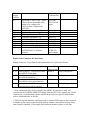
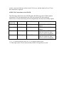
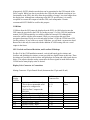
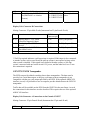
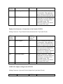
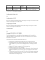
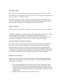
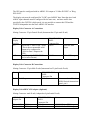
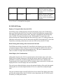
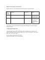
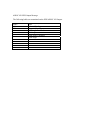
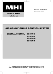
Installation Manual
Caution: Preliminary
Due to software development occurring at this time, this
manual may contain inaccuracies and omissions.
Manual Version: Preliminary
Date: 10/18/04
Grand Rapids Technologies, Inc.
REVISION HISTORY ..................................................................................................... 2
INTRODUCTION............................................................................................................. 2
WIRING CONSIDERATIONS ....................................................................................... 3
POWER CONNECTIONS............................................................................................... 3
GROUND CONNECTIONS ............................................................................................ 4
OTHER WIRING CONSIDERATIONS........................................................................ 4
DISPLAY UNIT INSTALLATION ................................................................................ 5
DISPLAY UNIT CHECKOUT PROCEDURE ............................................................. 5
AHRS INSTALLATION.................................................................................................. 5
AHRS/AIR DATA COMPUTER AND MAGNETOMETER CHECKOUT
PROCEDURE ................................................................................................................... 5
ALTITUDE ENCODER WIRING.................................................................................. 6
WARNING LIGHT OUTPUT......................................................................................... 6
CLOCK POWER.............................................................................................................. 6
AHRS TO DISPLAY UNIT WIRING ............................................................................ 6
AHRS TO MAGNETOMETER WIRING..................................................................... 7
INTER-DISPLAY UNIT COMMUNICATION ............................................................ 7
AUDIO OUTPUT.............................................................................................................. 7
LOCALIZER/GLIDESLOPE WIRING ........................................................................ 7
NAVIGATION RECEIVER WIRING ........................................................................... 7
ARINC 429 ADAPTER WIRING ................................................................................... 8
GARMIN 430 WIRING ................................................................................................... 9
GNX327/GNX330 TRANSPONDER ............................................................................ 14
GARMIN GPS 155XL / GNC 300XL............................................................................ 16
SL30/SL40 WIRING....................................................................................................... 19
Revision History
2/4/04 Corrected error. CNX80 showed pin P1-22 incorrectly as a serial input. Changed
this to P1-21.
10/15/04 Added new equipment interfaces.
Introduction
This document provides detailed descriptions of the wiring to the EFIS Horizon I Display
Units and AHRS/Air Data Computer (AHRS). The “Cable Description” document,
“AHRS Installation” diagram, and “Magnetometer Installation” diagram make up the set
of installation documents.
Wiring Considerations
The cable assembly supplied with the EFIS includes wires pre-installed in the connectors
that are certain to be used. Other connections to the EFIS, which may or may not be used,
are not installed in the d-sub connectors. Colored tefzel wires with d-sub connector
contacts pre-installed are included for these connections. The cable description diagram
includes recommended wire colors for each connection to the EFIS components.
When routing the wiring, the following guidelines should be considered.
•
•
•
•
Good practices for physical installation of the wiring should be followed, such as
grommets where wires pass through sheet metal, considering for chaffing and
interference with moving mechanisms, etc.
Cable lengths should include enough extra length to allow for servicing the
equipment. For example, the cables which plug into the display unit should be
long enough to allow them to be connected to display unit with the display unit
not installed in the instrument panel.
In general, routing of the wiring is not critical, as the EFIS is designed to be
tolerant of the electrical noise and other emissions typically found in aircraft.
Some consideration should be given to avoid routing wires near antennas, or other
locations that could impart high levels of electromagnetic signals on the wiring.
The checkout procedures should be completed to verify the EFIS is not affected
by radio transmissions on any frequency.
Power Connections
The display units and AHRS each include 3 isolated power input connections. This
allows redundant power sources, such as a main and secondary bus, and the possibly of a
third power source. Since the AHRS only consumes about 0.1 amps, and will operate
down to 9V, even 8 dry cells could be used as a source of emergency power. This would
allow many hours of operation from cells as small as AA. The display units consume
approximately 1 amp, making even a small 3 Amp-Hour gel cell a suitable emergency
source.
The configuration of the power supplied to the display unit(s) is left to the installer.
Considerations such as the number of power buses, the desire or not to supply one piece
of equipment with power from redundant buses (which in theory allows the possibility of
one device affecting both buses), the configuration of the electrical system with respect to
backup equipment, and so on, may dictate the best configuration for a particular airplane.
No provision is included within the display units for a power switch. If a power switch is
desired for the EFIS, the +12V power should be controlled with the switch (not ground).
The display units and AHRS include internal thermally-activated fuses. This protects the
equipment from internal electrical faults. Power supplied to the EFIS must pass through a
fuse or circuit breaker or fuse. It should be sized to allow at least 1.5 amps per display
unit, and 0.5 amps for the AHRS, with a maximum rating of 5 amps.
The AHRS and display units monitor all of there power inputs, and alarms are available
to annunciate the loss of any power source that was provided and is expected to be
working according to the “General Setup” menu.
The majority of the current flow into the display unit and AHRS will occur on the bus
with the highest voltage.
It is desirable to have the display units and AHRS off during the engine start if all of the
buses which power them are used for supplying power to the engine starter. This
maximizes the current available for the starter, and may extend the life of the CCFL
backlight in the display unit.
Ground Connections
The cable assembly provided includes 20 or 22 gauge wire for the ground return of the
display units. This will result in a voltage drop of about 0.015 V/foot, which is acceptable
for wire lengths up to 10 feet. If any of the analog inputs 1-8 are used for monitoring
which requires a high degree of precision, it is recommended that the ground wire be less
then 3 feet long, or that a large gauge wire (such as 18 gauge or larger) be spliced onto
the supplied ground wire which has been shortened to 1 foot or less. The localizer and
glideslope inputs are not affected by any voltage losses in the ground wire.
No uses for the analog inputs are specified at this time that require a high degree of
precision. Thus, these recommendations are allow for future growth.
Other Wiring Considerations
Depending on the other equipment installed in the airplane, switches may be necessary or
desirable for the following functions:
•
•
A switch to allow the autopilot to be controlled by the EFIS, or directly from the
GPS. The benefit of this switch is to allow the GPS to control the autopilot in the
even the display unit which normally commands the autopilot, is not functioning.
A switch may be necessary to manually select the localizer/glideslope deviation
indicators to be displayed. While most nav radios include a “ILS Tuned” signal
that the EFIS can use to activate the localizer/glideslope deviation displays, there
may not be similar output from GPS/Nav receivers which can drive these
indicators with either ILS data, or GPS data, when GPS data is being output.
Display Unit Installation
Mount the display unit(s) in the desired location in the instrument panel. The main
consideration in choosing a location is simply the ability to view display unit. Since the
display is fully sunlight-readable, no consideration for shielding the display unit from
sunlight is required. The use of nutplates behind the instrument panel greatly simplifies
the task of installing and removing the 4 screws used to retain the display unit in the
panel. #6 socket cap stainless steel screws are recommended.
Display Unit Checkout Procedure
1. Apply Power to the display unit. The LCD may flicker, and within 10 seconds,
the display should show the first page.
2. If multiple power buses connect to the display unit, turn off the display unit, and
apply power from each bus individually.
AHRS Installation
Follow the instructions provided on the “AHRS Mounting” diagram. Similarly,
temporarily install the magnetometer in the location you have chosen for it according to
the “Magnetometer Mounting” diagram. No periodic maintenance is required for these
devices, although it is desirable to mount them in locations that allow access to them if
necessary.
Be sure to mount the AHRS and magnetometer with the connector toward the rear of the
airplane. A standard level can be used to orient these two devices such that are both level
in roll, and equal in pitch. These devices must also be oriented to point in out the nose of
the airplane. This can be accomplished by adjusting the orientation of these devices so
they are parallel to a fuselage centerline. In cases where the magnetometer is mounted in
the wing, it may be possible to orient the magnetometer parallel to a wing rib, if these
ribs are oriented in the wing such that they are parallel to the fuselage centerline. This is
quite practical in airplanes such as Van’s RV’s.
Typically, the cable supplied for the EFIS will not have a d-sub connector installed on
magnetometer cable end. This makes it easier to route this cable through the airplane.
After the cable has been routed, the wires can be cut to length if desired, although new dsub pins would need to be installed. If the wires are not cut, inspect the d-sub connector
pins to verify they have not been damaged. Insert the indicated wire color into the
appropriate d-sub connector housing hole according to the cable description diagram. It
desired, the crimp-type d-sub connector can be replaced with a solder-type connector.
AHRS/Air Data Computer and Magnetometer Checkout Procedure
1. Apply power to a display unit to which the AHRS is connected, and the AHRS.
2. Select the “Set Menu” from the softkeys, and select the “AHRS Maintenance”
page.
3. Verify AHRS communications status is valid, and AHRS status is valid.
4. Scroll down this screen to the “Magnetic Heading” field. This is the raw magnetic
heading sensed by the magnetometer.
5. To verify the magnetic heading is reasonable, the following conditions must be
met.
a. The roll and pitch attitude data must be accurate.
b. The magnetometer must be in the same attitude as the AHRS.
c. The magnetometer must have been electrically connected to the AHRS
when the AHRS was turned on.
d. The magnetic heading should be accurate within 30 degrees for any
direction in which the airplane is pointed. This can be verified by
observing the “Magnetic Heading” data while position the airplane in
different directions. If this accuracy is not achieved, it is likely due to miswiring of the magnetometer connector, or magnetic disturbances in the
vicinity of the magnetometer.
6. The magnetometer calibration may now be performed. Refer to the user manual
for these procedures.
Altitude Encoder Wiring
Gray code outputs are provided for transponders that require this format for the data.
These outputs are provided on connector B. The corresponding output (such as A1, A2,
A4, etc.) from the display unit connects to the same input (A1, A2, A4, etc.) of the
transponder.
Warning Light Output
A warning and caution output are provided on connector B to drive external warning and
caution indicators. These output provide a path to ground when active, thus the indicator
should be wired with one of its terminals to aircraft power, and the other to this output.
The maximum current that can be controlled by this output is 0.2 amps.
Clock Power
Clock power allows the internal time-of-day clock to maintain its time while the EFIS is
turned off.
AHRS to Display Unit Wiring
The cable description document describes the wiring that is pre-installed between the
AHRS and the display unit. The only consideration of any consequence occurs in systems
which include multiple AHRS. Since a display unit can control only 1 AHRS, only the
display unit with a serial output to the AHRS can be used to command magnetometer
calibration, or be used to enter altimeter corrections into the associated AHRS.
The AHRS does not require any serial input to operate, although serial input to the AHRS
is required to active the magnetometer calibration, and to enter altimeter corrections.
Each AHRS includes 4 serial output drivers for convenient connections to 4 display units.
AHRS to Magnetometer Wiring
All magnetometer connections are made directly to its AHRS. This wiring includes the
power connections necessary for the magnetometer to operate. Each AHRS and
magnetometer pair is calibrated together for optimal accuracy, and thus this paring should
be maintained for installations which include more than one ARHS.
Inter-Display Unit Communication
Display units communicate between themselves so that most entries made during flight
can be made from any display unit, and will be applied to all. This communication is
accomplished by connecting the serial output to serial input such that all display units are
in this loop.
Audio Output
An audio output is provided. Future growth is planned to allow this output to provide a
warning tone, or possibly other type of audio output. This output may be connected to a
spare input on the aircraft’s intercom system. Volume level will be controlled by menu
settings within the display unit.
Localizer/Glideslope Wiring
The localizer/glideslope deviation indicators provided on the EFIS can be driven from
any ILS receiver, or combination nav/GPS receivers, such as the Garmin 430/530,
CNX80, etc. Specific wiring recommendations are provided for these systems below.
These inputs require practically no power from the nav receiver’s outputs, allowing the
nav receiver to be wired to as many display units as desired. Nav heads may also be
wired to these connections.
For redundancy purposes, it is desirable to connect these signals to all display units.
Navigation Receiver Wiring
When stand alone nav receivers are connected to the EFIS, the localizer and glideslope
deviation and flag connections are made to the EFIS localizer/glideslope deviation and
flag inputs. If the nav receiver includes an “ILS Tuned” output, indicating an ILS
frequency is selected on the nav radio, connect this to the display unit’s analog 1 input, as
shown in the following tables.
Display Unit Connector A Connections
Mating Connector: 25-pin Female D-sub (Instrument has 25-pin male D-sub)
EFIS
Display
Unit Pin
A-6
A-7
A-8
A-9
A-10
A-11
A-12
A-13
Function
Notes
Localizer Deviation + Left Input
Localizer Deviation + Right Input
Glideslope Deviation + Down
Glideslope Deviation + Up
Localizer Valid – Input
Localizer Valid + Input
Glideslope Valid – Input
Glideslope Valid + Input
Display Unit Connector B Connections
Mating Connector: 25-pin Male D-sub (Instrument has 25-pin Female D-sub)
Pin
B-21
Function
Analog Input 1 – ILS Tuned Input
Notes
Pull-Up Required**
** Pull-Up required indicates a pull-up resistor is required. If this input is also connected
to another system, such as a nav head, the pull-up resistor is not required as long as this
other system is installed. If this signal is not shared with other systems, a 10k ohm
resistor, connected with one lead to aircraft 12V power, and the other lead “tee-d” into
this connection is required.
ARINC 429 Adapter Wiring
The ARINC 429 adapter provides 2 serial inputs and 1 serial output that conform to the
ARINC 429 serial communication standard. The inputs may be configured for various
uses according to the other equipment installed in the airplane as described below. Each
input may be configured for any of the possible functions.
The ARINC429 output is used by the EFIS to generate data usable by a variety of
equipment, such as autopilots and gps receivers. The ARINC 429 output is can be
connected to as many ARINC 429 receivers as desired.
Garmin 430 Wiring
The following guidelines are provided for reference purposes only. It provides the
suggested methods for connecting this GPS to the EFIS display unit to allow optimal
performance of both units.
The interface between this GPS and the EFIS allows for:
•
•
•
•
•
•
GPS position, groundspeed and ground track to be provided to the EFIS.
GPS flight plan data to the EFIS
Display of Localizer/Glideslope data on the EFIS
Display of GPS CDI data to in the same format as localizer data
Transmission of air and fuel data to the GPS to allow RAIM integrity monitoring,
and other functions within the GPS related to fuel management, etc.
With the optional ARINC 429 interface, full VOR functionality is provided on the
EFIS, and selected course is transmitted to the 430 from the EFIS when the OBS
selection on the 430 is in
GPS Data to EFIS
The Garmin 430 must be configured for “AVIATION” output on one its serial output
channels. This output is connected to a serial input of the display unit(s) (serial input 5 is
recommend), and the input configured as “AVIATION” input at 9600 baud.
EFIS to GPS Data
Configure the display unit for Fuel/Air Data on one of its serial outputs, and connect this
serial output to one of the 4 serial inputs to the Garmin 430. Configure the Garmin 430
for “Shadin FADC” on this input. This will allow fuel and air data to be supplied to the
GPS, allowing the RAIM integrity monitoring, and other functions to operate in the GPS.
Alternatively, the gray code altitude output can be connected from the EFIS to the GPS,
although no fuel, or other data will be provided to the GPS which would enhance its
functionality.
VOR Data
To display VOR data on the EFIS, the optional ARINC 429 interface is required. The
ARINC input on the interface is connected to the VOR/ILS ARINC 429 output from the
GPS (connector P4006, pins 23 and 24). If this interface is used, it may be possible to
delete connections listed with an * in the “Other Connections” section.
Display Unit Connector A Connections
Mating Connector: 25-pin Female D-sub (Instrument has 25-pin male D-sub)
EFIS
Display
Unit Pin
A-5
A-6
A-7
A-8
A-9
A-10
A-11
A-12
A-13
A-22
Function
Garmin 430
Notes
Connector-Pin
Serial Out 4 – RS232 Out – Spare
(This is the recommended serial
output to be configured as
“Fuel/Air Data” output to the
GNS-430.
Localizer Deviation + Left Input
Localizer Deviation + Right Input
Glideslope Deviation + Down
Glideslope Deviation + Up
Localizer Valid – Input
Localizer Valid + Input
Glideslope Valid – Input
Glideslope Valid + Input
Serial Input 5 – RS232 GPS Data
In (NMEA0183 or Aviation
Format)
Any of the
RS-232 serial
inputs
P4001-21*
P4001-22*
P4001-28*
P4001-27*
P4001-24*
P4001-23*
P4001-30*
P4001-29*
Any one of
the RS-232
serial outputs
Display Unit Connector B Connections
Mating Connector: 25-pin Male D-sub (Instrument has 25-pin Female D-sub)
Pin
Function
B-21
Analog Input 1 – Reserved for future
growth/ILS Tuned Input
Analog Input 2 – GPS Deviations
Active (true when low)
Analog Input 3 – VOR/ILS
Deviations Active (true when low)
Analog Input 4 - OBS Select (this
connection may not be required)
B-20
B-19
B-18
Garmin 430
Notes
Connector-pin
P4006-29
Pull-Up Required**
P4001-2
Pull-Up Required**
P4001-1
Pull-Up Required**
P4001-7
Pull-Up Required**
* These connections may not be required if the ARINC 429 interface is used, and
connected to the VOR/ILS ARINC 429 Output from the GPS. These signals may also be
connected to a conventional nav head, without the need for any special considerations
such as isolation diodes, or the like.
** Pull-Up required indicates a pull-up resistor is required. If this input is also connected
to another system, such as a nav head, the pull-up resistor is not required as long as this
other system is installed. If this signal is not shared with other systems, a 10k ohm
resistor, connected with one lead to aircraft 12V power, and the other lead “tee-d” into
this connection is required.
ARINC 429 Connections to the GNS430
The following connections to the GNS430 allow the EFIS to provide VOR navigation
information. The data transmitted to the EFIS also includes ILS data, making it
unnecessary to connect the analog localizer and glideslope deviation and validity signals.
ARINC 429
Adapter Pin
C-1 (or C-3)*
Function
GNS430 Pin
Notes
VOR/ILS Input
J4006-24
C-2 (or C-4)*
VOR/ILS Input
J4006-23
C-5
EFIS Output
J4001-48**
C-9
EFIS Output
J4001-49**
ARINC 429 A - VOR/ILS
Output
ARINC 429 B - VOR/ILS
Output
ARINC 429 A - EFIS Output.
May also connect to other
devices, such as an autopilot.
ARINC 429 B - EFIS Output
May also connect to other
devices, such as an autopilot.
* C-1, C-2 must be used as a pair, or C-3,C-4 must be used as a pair.
** If this input to the G430 is used, the other ARINC 429 input may be used.
Garmin CNX 80 Wiring
The following guidelines are provided for reference purposes only. It provides the
suggested methods for connecting this GPS to the EFIS display unit to allow optimal
performance of both units.
At the time of this writing, lateral and vertical deviation data is only available via analog
interfaces, as described below.
The interface between this GPS and the EFIS allows for:
•
•
•
•
•
GPS position, groundspeed and ground track to be provided to the EFIS.
GPS flight plan data to the EFIS
Display of Localizer/Glideslope data on the EFIS
Display of GPS lateral and vertical deviation data, displayed in the same format as
ILS data.
Transmission of air and fuel data to the GPS to allow RAIM integrity monitoring,
sequencing of altitude dependent type waypoints, and other functions within the
GPS related to fuel management, etc.
GPS Data to EFIS
The CNX80 must be configured for “MAPCOM” output on the RS-232 serial output
channel used to send data to the EFIS. The CNX80 can transmit this data on any of 3
outputs, giving the installer a choice dependent on other devices connected to the
CNX80. These choices are listed in the table below.
This CNX80 output is connected to any serial input of the display unit(s) (serial input 5
of the EFIS is recommend, with its pin number is listed in the table below), and the
display unit serial input configured as “AVIATION” input at 9600 baud.
EFIS to GPS Data
The CNX80 must be configured for “FADC” input on the RS-232 serial output channel
used to receive this data from the EFIS. The CNX80 can receive this data on any of 3
inputs, giving the installer a choice dependent on other devices connected to the CNX80.
These choices are listed in the table below.
This CNX80 input is connected to a serial output from any display unit(s) which receives
AHRS and EIS engine data (if installed). Serial output 5 of the EFIS display unit is
recommended, with its pin number is listed in the table below). The display unit serial
input must be configured as “Fuel/Air Data (S Format)” output at 9600 baud.
Alternative EFIS to GPS Data Connections
Alternatively, RS232 altitude encoder data can be transmitted to the GPS instead of the
FADC output. While less data is provided to the GPS with this method (resulting in less
functionality in the GPS), this does allow the possibility of using 1 less serial output from
the display unit. Although not conforming to the RS-232 specification, it is usually
acceptable to connect this output to both the GPS, and a transponder. Garmin
recommends RS232 RxD8 be used for this purpose.
VOR Data
VOR data from the GPS cannot be displayed on the EFIS. An OBS selection into the
GPS cannot be provided by the EFIS. According to page 2-3 of the CNX-80 installation
manual, full VOR functionality is available without an external CDI, although this
seemed to conflict with the pilots manual. While you can perform the equivalent
navigation function of flying on a selected radial to/from a VOR, the CNX80 uses GPS
for this guidance. If you want to see actual VOR data, you will need a separate nav head.
Rumor has it this may be corrected with the addition of VOR bearing data via a serial
output in the future.
GPS Vertical and Lateral Deviation, and Localizer/Glideslope
Per Rev E of the CNX Installation manual, vertical and lateral gps deviations, and
localizer and glideslope deviations, are not provided in a digital format at this time. These
deviations are provided via the localizer and glideslope deviation and valid signals shown
below. This requires that the analog connections for these signals be made between the
CNX80 and as many display units as desired.
Display Unit Connector A Connections
Mating Connector: 25-pin Female D-sub (Instrument has 25-pin male D-sub)
EFIS
Display
Unit Pin
A-5
A-6
A-7
A-8
A-9
A-10
A-11
A-12
Function
CNX80
Connector-Pin
Notes
Serial Out 4 – RS232 Out – Spare
(This is the recommended serial
output to be configured as
“Fuel/Air Data” output to the
GNS-430.
Localizer Deviation + Left Input
Localizer Deviation + Right Input
Glideslope Deviation + Down
Glideslope Deviation + Up
Localizer Valid – Input
Localizer Valid + Input
Glideslope Valid – Input
P1-4
P1-21
P5-1
Use any 1 of
these.
P7-14
P7-13
P7-31
P7-30
P7-29
P7-10
P7-32
A-13
A-22
Glideslope Valid + Input
Serial Input 5 – RS232 GPS Data
In (NMEA0183 or Aviation
Format)
P7-28
P1-5 RS232 TxD1
P1-22 RS232 TxD2
P5-21 RS232 TxD5
Use any 1 of
these.
Display Unit Connector B Connections
Mating Connector: 25-pin Male D-sub (Instrument has 25-pin Female D-sub)
Pin
Function
B-21
Analog Input 1 – ILS Tuned
(Precision Approach) Input
Analog Input 2 – GPS Deviations
Active
Analog Input 3 – VOR/ILS
Deviations Active
B-20
B-19
CNX80
Notes
Connector-pin
P5-68
Pull-Up Required**
P7-17
Pull-Up Required**
P7-18
Pull-Up Required**
** Pull-Up required indicates a pull-up resistor is required. If this input is also connected
to another system, such as a nav head, the pull-up resistor is not required as long as this
other system is installed. If this signal is not shared with other systems, a 10k ohm
resistor, connected with one lead to aircraft 12V power, and the other lead “tee-d” into
this connection is required.
GNX327/GNX330 Transponder
The EFIS can provide altitude encoding data to these transponders. The data must be
provided via a serial data output, as the gray code input to these transponders is not
compatible with the gray code output provided by the EFIS. If the optional ARINC 429
interface is used, it is preferable to use its output to provide altitude data to the GNX330
transponder.
Traffic data will be available on the EFIS from the GNX330 in the near future. As such,
the connections for this interface are also described. This requires the use of the optional
ARINC 429 interface.
Display Unit Connector A Connections to the Garmin GNX327
Mating Connector: 25-pin Female D-sub (Instrument has 25-pin male D-sub)
EFIS
Function
GNX327
Notes
Display
Unit Pin
A-1
Pin Number
Serial Output 6
19
Tbd
GPS Data Output
2
Provides Altitude Encoding Data
to Transponder. This output may
also be wired to a GNS430/530 or
other devices that require this data.
Optional Connection – Allows
Transponder to provide flight time,
and automatic switching to and
from standby mode. This
connection is made to the EFIS if
no external GPS is used.
Display Unit Connector A Connections to the Garmin GNX330
Mating Connector: 25-pin Female D-sub (Instrument has 25-pin male D-sub)
EFIS
Display
Unit Pin
A-1
Function
Serial Output 6
GNX330
P3271 Pin
Number
24
B-tbd
Enable/Disable TIS
46
Tbd
GPS Data Output.
22
Notes
Provides Altitude Encoding Data
to Transponder. This output may
also be wired to a GNS430/530 or
other devices that require this data.
TIS Select – This connection is
made to pin 46 of a GNS430/530
series unit if installed. If no
GNS430/530 is installed, make the
connection to the display unit.
Optional Connection – Allows
Transponder to provide flight time,
and automatic switching to and
from standby mode. This
connection is made to the EFIS if
no external GPS is used.
ARINC 429 Adapter wiring for the GNX330
Mating Connector: 9-pin male D-sub (Adapter has 9-pin female D-sub)
ARINC 429
Function
GNX330
Notes
Adapter Pin
C-1 or (C-3)*
C-2 or (C-4)*
Traffic Display
Traffic Display
P3271 Pin
Number
30
28
ARINC 429 A - Traffic Data
ARINC 429 B - Traffic Data
*C-1, C-2 or C-3, C4 must be use as pairs.
Configuring the Display Unit
tbd
Configuring the GNX327
Refer to the GNX327 installation manual, and configure serial input 1 for the fuel/air data
format, and serial input 2 for “GPS” format.
Configuring the GNX330
Refer to the GNX330/330D installation manual, and configure serial input 1 for GPS
format, and serial input 2 for tbd format.
GNX330 Traffic
tbd
Garmin GPS 155XL / GNC 300XL
The following guidelines are provided for reference purposes only. It provides the
suggested methods for connecting this GPS to the EFIS display unit to allow optimal
performance of both units.
The interface between this GPS and the EFIS allows for:
•
•
•
•
•
•
GPS position, groundspeed and ground track to be provided to the EFIS.
GPS flight plan data to the EFIS, including approaches, although curved paths
(such as DME arcs, procedure turns, holding patterns) are not displayed at this
time.
Display of GPS lateral (cross-track or CDI) deviation data.
Ability to set course in to a GPS waypoint
For EFIS installations that include the ARINC 429 interface, selected course and
magnetic heading data is sent to the GPS, and CDI scaling can be read from the
GPS.
Transmission of air and fuel data to the GPS to allow RAIM integrity monitoring,
sequencing of altitude dependent type waypoints, and other functions within the
GPS related to fuel management, etc.
GPS Data to EFIS
The GPS RS-232 serial output channel 1 is used to send data to the EFIS. This data is
provided in the Aviation format. The GPS 155XL/GNC 300XL must be configured to set
up serial output 1 as "Aviation" format.
This output is connected to any serial input of the display unit(s) (serial input 5 of the
EFIS is recommended, with its pin number is listed in the table below), and the display
unit serial input configured as “Aviation/Mapcom” input at 9600 baud.
EFIS to GPS Data
The GPS must be configured for “shadin-fuel” input on the RS-232 serial input channel
1.
This input is connected to a serial output from any display unit(s) which receives AHRS
and EIS engine data (if installed). Serial output 4 of the EFIS display unit is
recommended, with its pin number is listed in the table below). The display unit serial
input must be configured as “Fuel/Air Data (S Format)” output at 9600 baud.
Alternative EFIS to GPS Data Connections
Alternatively, RS232 serial altitude encoder data that is transmitted to the transponder
can also be wired to the GPS instead of the fuel/aid data output. This may limit the
amount of data is provided to the GPS to accommodate the needs of the transponder
(resulting in less functionality in the GPS), this does allow the possibility of using 1 less
serial output from the display unit. Although not conforming to the RS-232 specification,
it is usually acceptable to connect this output to both the GPS, and a transponder.
ARINC 429 Connections
At the time of this writing it is believed (although not confirmed through testing) that
ARINC 429 connections to the GPS are not required. The benefit of using the ARINC
429 interface is as follows:
•
•
•
CDI scaling information is provided directly by the GPS. Without this scaling
information, the EFIS attempts to duplicate the scaling based flight plan data.
Selected Course Data is provided to the GPS from the EFIS. This allows the CDI
analog output of the GPS to operate correctly when waypoint sequencing is in the
"HOLD" state.
Magnetic Heading information is provided to the GPS.
The GPS must be configured with its ARINC 429 output as "Collins PL2 EFS" or "King
EFS 40/50".
The display unit must be configured for "LOW" speed ARINC data. Note that since both
ARINC input channels must be configured for the same rate, and since traffic data
provided by the GNX330 is high speed, it is not possible to connect this GPS and the
GNX330 transponder into the same ARINC 429 interface.
Display Unit Connector A Connections
Mating Connector: 25-pin Female D-sub (Instrument has 25-pin male D-sub)
Function
EFIS
Display
Unit Pin
A-5
Serial Out 4 – RS232 Out – Spare
(This is the recommended serial
output to be configured as
“Fuel/Air Data” output to the
GPS.)
Serial Input 5 – RS232 GPS Data
In (Aviation Format)
A-22
GPS 155XL/GNC
300XL
Connector-Pin
J101-17
Notes
J101-24
Main GPS output
Fuel/Air Data
Input
Display Unit Connector B Connections
Mating Connector: 25-pin Male D-sub (Instrument has 25-pin Female D-sub)
Pin
Function
B-18
Hold/Sequence
Notes
GPS 155XL/GNC
300XL
Connector-Pin
J102-13
Connects also to Garmin
MD41 Switch/Annunciator
panel, pin 9
Display Unit ARINC 429 Adapter (Optional)
Mating Connector: male D-sub (Adapter has 9-pin female D-sub)
ARINC 429
Adapter Pin
Function
C-1 (or C-3)*
C-2 (or C-4)*
GPS Output
GPS Output
GPS 155XL/GNC
300XL
Connector-Pin
J101-16
J101-15
Notes
ARINC 429 A - GPS Output
ARINC 429 B - GPS Output
C-5
EFIS Output
J101-32
C-9
EFIS Output
J101-33
ARINC 429 A - EFIS Output.
May also connect to other
devices, such as an autopilot or
GNS430.
ARINC 429 B - EFIS Output
May also connect to other
devices, such as an autopilot or
GNS430.
*C-1, C-2 or C-3, C4 must be use as pairs.
SL30/SL40 Wiring
Display of Navigation Data from the SL30
The EFIS provides an HSI and others functions that display and use the VOR bearing
data to provided by the SL30 Nav/Com radio. Localizer and glideslope deviation data is
also displayed on the EFIS from this radio. This data is transmitted to the EFIS display
unit via an RS-232 output from the nav radio. While the RS-232 connection is the
preferred method for communicating this data to the EFIS, the SL30’s analog outputs for
glideslope and localizer may also be connected to the EFIS. If both the RS-232 serial data
connection, and analog connections are made, the EFIS will use the RS-232 data.
Radio Tuning and Loading of Pre-Sets in the SL30/SL40
The EFIS has the ability to load the SL30 and SL40 with frequency pre-sets to allow
convenient selection of these frequencies from the front panel controls of the radio. For
the SL30, the EFIS can also tune the navigation radio. This data is transmitted to the
radio via an RS-232 output from the EFIS display unit.
Multi-Display Unit Considerations
Although the data from the SL30 is communicated to other display units via the interdisplay unit serial data connections, allowing this data to appear on all display units, it is
preferable to connect the serial data output from the SL30 to at least 2 display units.
Connecting the serial output from the SL30 to multiple display units allows its data to be
displayed in the event one display unit is not functional.
The serial ports within the display unit provide minimal loading of the serial data signals,
allowing the one serial data output from the SL30 to be connected to multiple display
units.
Only one serial data output to the SL30/SL40 may be provided. If the display unit which
provides this (tuning) data to the SL30/SL40 was not operational, the SL30/SL40 would
be tuned by its front panel controls.
Display Unit Connector A Connections
Mating Connector: 25-pin Female D-sub (Instrument has 25-pin male D-sub)
EFIS
Display
Unit Pin
A-2
Function
A-20
Serial Input 1*
Serial Output 1*
SL30/SL40
Notes
Only 1 display
unit may provide
this connection.
This output from
the SL30 may be
connected to
multiple display
units.
*Serial input 1 is the recommended port for this data, although any port on the display
unit may be used.
Configuring the Display Unit
Using the general setup menu, set the display unit to which the above connections are
made to 9600 baud. For the serial data output, select “SL30/SL40 Output”. For the serial
input, select “SL30/SL40 Input”.
Are any setups required for the SL30/SL40?
Does the SL40 require 2-way communication?
ARINC 429 EFIS Output Message
The following labels are transmitted on the EFIS ARINC 429 Output.
Label
100
320
Data
Selected Heading
Magnetic Heading
Roll Angle Command
Roll Angle
Pitch Angle Command
Pitch Angle