1
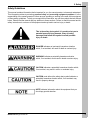
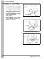
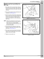
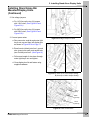
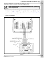
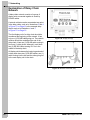
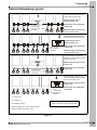
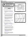
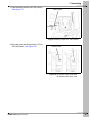
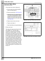
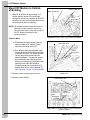
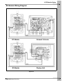
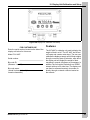
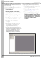
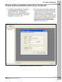
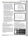
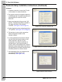
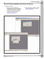
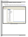
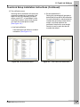
Integra Feed-Link
Installation and Operation Manual
PNEG-1323
Date: 05-03-08
PNEG-1323
All information, illustrations, photos, and specifications in this manual are based on the latest
information available at the time of publication. The right is reserved to make changes at any
time without notice.
2
PNEG-1323 Integra Feed-Link
Table of Contents
Contents
Chapter 1 Getting Started.................................................................................................................................. 4
Introduction ........................................................................................................................................ 4
Selecting the Load Cell .................................................................................................................... 4
Tools Needed for Installation ............................................................................................................. 4
Chapter 2 Safety ................................................................................................................................................. 5
Safety Guidelines .............................................................................................................................. 5
Chapter 3 Part Identification ............................................................................................................................. 7
Chapter 4 Load Cell Installation ..................................................................................................................... 10
Removing Anchor Nuts ...................................................................................................................
Raising the Bin ................................................................................................................................
Installing the Load Cell Base ...........................................................................................................
Install Load Cell and Attach to Bin Leg ...........................................................................................
Installing Load Cell Spacer ..............................................................................................................
Running Load Cell Cables ...............................................................................................................
10
11
12
13
14
15
Chapter 5 Installing Stand Alone Display Units ............................................................................................ 16
Mounting Display and Junction Boxes ............................................................................................ 16
Installing Stand Alone Bin Mounted Display Units .......................................................................... 17
Chapter 6 Stand Alone Remote Mounted Display Units............................................................................... 20
Junction Box .................................................................................................................................... 20
Junction Cable to Inside Mounted Display Unit ............................................................................... 21
Chapter 7 Networking ...................................................................................................................................... 22
Explanation of Daisy Chain Network ...............................................................................................
Optional Networking Layouts .........................................................................................................
Network Wiring of Display Unit ........................................................................................................
Network Collector Wiring .................................................................................................................
22
23
24
25
Chapter 8 Water Meter Option ........................................................................................................................ 28
Optional Water Meter ...................................................................................................................... 28
Chapter 9 RF Module Option........................................................................................................................... 29
Mount RF Module to Bin Leg ...........................................................................................................
Mount RF Module to Outside of Building .........................................................................................
RF Module Wiring Diagram .............................................................................................................
Possible RF Module Layouts ...........................................................................................................
29
30
31
32
Chapter 10 Display Unit Calibration and Setup............................................................................................. 33
Features ........................................................................................................................................ 33
Display Unit Setup ......................................................................................................................... 34
Troubleshooting Display Unit ........................................................................................................ 37
Chapter 11 Feed-Link Software ...................................................................................................................... 38
Feed-Link Software Installation Instructions ................................................................................. 38
Feed-Link Setup Instructions ......................................................................................................... 38
Chapter 12 Troubleshooting ........................................................................................................................... 52
Chapter 13 Warranty ........................................................................................................................................ 53
PNEG-1323 Integra Feed-Link
3
1. Getting Started
Introduction
READ THIS MANUAL carefully to learn how to properly use and install equipment. Failure to do so could
result in personal injury or equipment damage.
INSPECT the shipment immediately upon arrival. The customer is responsible for ensuring that all
quantities are correct. The customer should report and note any damage or shortage on the bill of lading
to justify their claim to the transport company.
THIS MANUAL SHOULD BE CONSIDERED a permanent part of your equipment and should be easily
accessible when needed.
This warranty provides you the assurance that the company will back its products when defects appear
within the warranty period. In some circumstances, the company also provides field improvements, often
without charge to the customer, even if the product is out of warranty. Should the equipment be abused,
or modified to change its performance beyond the factory specifications, the warranty will become void
and field improvements may be denied.
Selecting the Load Cell
Use the proper load cell for the application. Two sizes of load cells are available, a 5000 lbs. per leg load
cell and 10000 lbs. per leg load cell. To determine which load cell to use, add the empty bin weight to
the maximum weight of feed the bin will hold in lbs. Divide this total maximum weight by the number of
legs the bin has. If this number is 5000 lbs. or less, use the 5000 lbs. cell, (INT-4809). If this number is
over 5000 lbs., use the 10000 lbs. load cell (INT-4810). This system cannot be used if the weight is
greater than 10000 lbs.
Empty bin weight (lbs.)
+
Max weight of feed bin will hold (lbs.)
= Load cell weight
Number of bin legs
Tools Needed for Installation
Tools
Tools that can be used during installation may include:
1. Drill
2. Crescent wrench
3. Reciprocating saw
4. Wire cutters
5. Jack lift
6. Impact or ratchet
7. Wire ties
NOTE: Follow all operating and safety guidelines that were provided with the tools.
4
PNEG-1323 Integra Feed-Link
2. Safety
Safety Guidelines
This manual contains information that is important for you, the owner/operator, to know and understand.
This information relates to protecting personal safety and preventing equipment problems. It is the
responsibility of the owner/operator to inform anyone operating or working in the area of this equipment
of these safety guidelines. To help you recognize this information, we use the symbols that are defined
below. Please read the manual and pay attention to these sections. Failure to read this manual and its
safety instructions is a misuse of the equipment and may lead to serious injury or death.
This is the safety alert symbol. It is used to alert you to
potential personal injury hazards. Obey all safety
messages that follow this symbol to avoid possible
injury or death.
DANGER indicates an imminently hazardous situation
which, if not avoided, will result in death or serious injury.
WARNING indicates a potentially hazardous situation
which, if not avoided, could result in death or serious injury.
CAUTION indicates a potentially hazardous situation which,
if not avoided, may result in minor or moderate injury.
CAUTION used without the safety alert symbol indicates a
potentially hazardous situation which, if not avoided, may
result in property damage.
NOTE indicates information about the equipment that you
should pay special attention.
PNEG-1323 Integra Feed-Link
5
2. Safety
Install and Operate Electrical Equipment Properly
Electrical controls should be installed by a qualified electrician
and must meet the standards set by the National Electrical Code
and all local and state codes.
Disconnect and lock out all power sources before installing
wires/cables or servicing equipment.
Electric Shock Hazard
Prepare for Emergencies
Be prepared if fire starts.
Keep a first aid kit and fire extinguisher handy.
Keep emergency numbers for doctors, ambulance service,
hospital and fire department near your telephone.
Keep Emergency Equipment
Quickly Accessible
Wear Protective Clothing
Wear close fitting clothing and safety equipment appropriate
to the job.
Eye Protection
Remove all jewelry.
Long hair should be tied up and back.
Gloves
Safety glasses should be worn at all times to protect eyes
from debris.
Steel Toe Boots
Wear gloves to protect your hands from sharp edges on
plastic or steel parts.
Wear steel toe boots to help protect your feet from falling
debris. Tuck in any loose or dangling shoe strings.
Respirator
A respirator may be needed to prevent breathing potentially
toxic fumes and dust.
Wear hard hat to help protect your head.
6
Hard Hat
PNEG-1323 Integra Feed-Link
3. Part Identification
Figure 3A INT-4807: Display Unit
Figure 3D INT-4808: Network Collector
(Includes Feed-Link Software)
Figure 3B INT-4813: Display Unit Lid Board
Figure 3E INT-4814: Display Unit Base Board
Figure 3C INT-4830 Junction Box
(Includes bin leg mounting bracket)
Figure 3F INT-4812: Bin Leg Mounting Bracket
(for display unit)
PNEG-1323 Integra Feed-Link
7
3. Part Identification
Figure 3G INT-4817: Load Cell Spacer
Figure 3H
INT-4809: 5000 lbs. Load Cell
INT-4810: 10000 lbs. Load Cell
Figure 3J
INT-4819: 1000' Roll of RS-485 Communication Wire
INT-4820: 500' Roll of RS-485 Communication Wire
Figure 3K
INT-4818-25: 25' of 10 Wire Cable for Junction Boxes
INT-4818-50: 50' of 10 Wire Cable for Junction Boxes
INT-4818-75: 75' of 10 Wire Cable for Junction Boxes
INT-4818-100: 100' of 10 Wire Cable for Junction Boxes
Figure 3I INT-4815: RF Module
8
PNEG-1323 Integra Feed-Link
3. Part Identification
Figure 3L RF Mounting Bracket
PNEG-1323 Integra Feed-Link
Figure 3M
INT-4822-25: 25' of 4 Wire Cable for RF Modules
INT-4822-50: 50' of 4 Wire Cable for RF Modules
INT-4822-75: 75' of 4 Wire Cable for RF Modules
INT-4822-100: 100' of 4 Wire Cable for RF Modules
9
4. Load Cell Installation
Removing Anchor Nuts
1. Use a 3/4" wrench or crescent to remove the
nut and washer from the anchor bolt on the
bin leg. (See Figure 4A.)
2. Remove side bolts using 9/16" wrench and
impact wrench or ratchet.
(See Figure 4B and Figure 4C.)
Anchor base plate
3/4" Wrench
3. Repeat on all bin legs.
Figure 4A Removing Nut from Anchor Bolt
Side bolts
9/16" wrench
Impact wrench
Figure 4B Remove leg anchor base plate side bolts
using impact wrench and wrench.
Bin leg
Anchor base plate
Figure 4C All bolts, nuts, and washers removed from
anchor base plate.
10
PNEG-1323 Integra Feed-Link
4. Load Cell Installation
Raising the Bin
1. Place 4 x 4 spanner board under bin hopper
braces. (See Figure 4D.)
Jack
2. Center lift jack under 4 x 4 spanner brace.
(See Figure 4D.)
3. Lift bin with jack about 4". This should lift two
(2) bin legs. (See Figure 4E.)
4. Remove leg anchor base plate.
Only install load cells on an
empty bin. Lifting a bin with
feed in it can result in damage
to the bin and potential
personal injury.
4 x 4 Spanner board
Figure 4D Jacking Up the Bin
Lifted bin leg
Anchor base plate
Figure 4E Lift Bin about 4"
PNEG-1323 Integra Feed-Link
11
4. Load Cell Installation
Installing the Load Cell Base
1. Shortening the anchor bolt may be required.
It can protrude no more than 1-1/4" above
the foundation. (See Figure 4F.) NOTE: You
may find it easier to put the nut on the bolt
and cut the bolt flush with the nut. This way
the threads are not stripped on the bolt, and
there is not a problem getting the nut on.
2. Position load cell base under bin leg and
around anchor bolt as shown.
(See Figure 4G.)
3. Replace washer and nut onto anchor bolt.
DO NOT tighten fully until assembly is
complete. (See Figure 4H.)
Anchor bolt
Reciprocating saw
Figure 4F Cut anchor bolt so it sticks up less than
1-1/4" from foundation.
Bin leg
Load cell base
Figure 4G Slide Cell Base Under Leg
Load cell base
Wrench
Figure 4H Leave anchor bolt loose until assembly
is complete.
12
PNEG-1323 Integra Feed-Link
4. Load Cell Installation
Install Load Cell and Attach to
Bin Leg
Top bracket
Load cell
1. Place load cell into load cell base, lining up
the holes. Line up the holes in the side of the
load cell with the holes in the side of the load
cell base.
2. Place pins through the holes and fasten with
a cotter pin. (See Figure 4I.)
Cotter pins
3. Attach load cell top bracket to the load cell by
lining up the holes on the side and fastening
with a pin and cotter pin. Make sure the
tongue on the bracket is on the inside side of
the bin leg.
Pins
Figure 4I Install Load Cell
NOTE: The bin leg should rest on the load cell
bracket. DO NOT drill mounting holes too
high on the leg or the bolts will be
supporting the weight of the bin rather than
the load cell bracket.
4. Fasten load cell top bracket to the bin leg
using bolt, washer and nut through the slot in
the bracket. (See Figure 4J.)
5. Drill a hole into the leg through the top hole
(hole above slot) fastening to leg using bolts,
washers, and nuts included.
6. Tighten nut on anchor bolt.
PNEG-1323 Integra Feed-Link
Drill bin leg through
top hole of bracket
Figure 4J Drill top hole through bin leg, using top
bracket as a guide.
13
4. Load Cell Installation
Installing Load Cell Spacer
1. The unique patented (Patent #6636820)
field calibration system utilized by Feed-Link
makes it possible to monitor the weight of
feed without requiring a load cell under every
leg of the bin. This feature allows for the
most economical installation possible. For
monitoring feed consumption, placing a load
cell under every leg will provide maximum
accuracy. If a bin leg does not have a load
cell installed, a load cell spacer will
be needed.
Figure 4L Load Cell Spacer Position for 5000 lbs.
2. To Install a load cell spacer to a bin leg,
follow the same steps as if you were
installing a load cell except substitute the
spacer for the load cell.
3. The same spacer is used for both the
5000 lbs. and 10000 lbs. bins, the
positioning of the spacer will determine if it is
a 5000 lbs. or 10000 lbs. spacer. The
5000 lbs. position will place the spacer
approximately 1/8" below the top of the cell
base. (See Figure 4L.) The 10000 lbs.
position will place the spacer approximately
1/8" above the top of the cell base.
(See Figure 4M.)
Figure 4M Load Cell Spacer Position for 10000 lbs.
4. DO NOT position the spacer as in Figure 4N.
The top load cell bracket is too far from the
cell base and too close to the center of the
spacer, which puts the bin leg out
of alignment.
Load cells
Load cell
spacer
Maximum accuracy
Minimum cost
5000 lbs. Pin placement
Hole for top bracket
Figure 4N Incorrect position of the load cell spacer.
Note how the load cell top bracket is too far from the
load cell base.
Spacer
10000 lbs. Pin placement
Hole for top bracket
Spacer
Figure 4K
14
PNEG-1323 Integra Feed-Link
4. Load Cell Installation
Running Load Cell Cables
Wire tie
1. Label both ends of the load cell cable with
the load cell number. Numbers will range
from 1 through 8. Labeling the load cell
cables will identify what terminals to use
when connection wires to display unit
in Installing Stand Alone Display Units on
Page 16. It will also expedite troubleshooting
if any problems should arise.
2. Run cable from load cell up bin leg using wire
ties (not included) to fasten into place. Run
cable along the cross brace to the center of
the bin. Then take cable around bin boot and
back up the leg that the display or junction
box is mounted to Figure 4O, Figure 4P and
Figure 4Q.
3. Repeat Step 1 and Step 2 for each load cell.
Wire
Figure 4O Fasten Wires with Wire Ties
Hole in leg
Load
cell
cable
Wire tie
Figure 4P Run wire tie through holes in
bin legs to attach cable to legs.
Wire
Cross brace
Bin boot
Figure 4Q Run wires around the boot of the bin.
PNEG-1323 Integra Feed-Link
15
5. Installing Stand Alone Display Units
Mounting Display and Junction Boxes
The display can be mounted either directly onto
the bin leg or remotely, up to 100' away, such as
inside a nearby building.
When mounted remotely, a junction box must be
used to extend the load cell wires from the bin to
the display unit. The junction box can be mounted
to the bin leg similar to the display shown.
See Figure 5C.
1. Attaching display unit mount to bin leg
Bin mount
bracket
Bin leg
a. Take display mount and slide it around
the bin leg. (See Figure 5A.)
Figure 5A Bin Mount Bracket Attached to Bin Leg
b. Attach to leg using 3/8" x 1-1/2" HHCS
bolt and hex nylock nuts. No drilling is
required. (See Figure 5B.)
Nut
c. Attach display box to the mount using the
three (3) #10 nuts provided.
2. Attaching junction box to bin leg (Bin leg
mounting bracket is included with
junction box.)
a. Attach junction box and bin leg mounting
bracket to bin leg using 3/8" x 1-1/2"
HHCS bolt and hex nylock nuts. No
drilling is required. (See Figure 5B.)
3/8" x 1-1/2"
HHCS Bolt
Bracket
Figure 5B Close-up of Bin Mount Bracket on Leg
3. Attaching RF module mount to bin
a. See RF Module Option on Page 29.
Bracket
Display
unit
Figure 5C Display Mounted Outside on Bin Leg
16
PNEG-1323 Integra Feed-Link
5. Installing Stand Alone Display Units
Always make sure all power is
disconnected and locked out
while display unit cover is OFF.
Multi-hole grommet
Plug
Installing Stand Alone Bin
Mounted Display Units
A
1. Load cell wires
B
a. Slide all load cell cables through
grommet cap. (See Figure 5E-A.)
Multi-hole grommet
b. Run load cell cables into multi-hole
grommet by sliding cables through slit on
side of grommet. (See Figure 5D-A.)
c. Run cables through hole in display box,
giving some extra cable length for
easier installation.
d. To make load cell connections, remove
terminals strips. Insert wires into correct
terminals and tighten lugs. (See Figure 5F
and Wiring Diagram on Page 18.)
e. Gently pull out any excess length of
cable out through the grommet.
Connector
Figure 5D A) Load cell wire in multi-hole grommet.
B) Grommet wedged into connector.
Load cell wires
Power wires
(grommet not included)
Water
meter wires
Daisy chain
“OUT” wires
or RF wires
Grommet cap
A
f. Wedge grommet into hole.
(See Figure 5D-B.)
Daisy chain “IN” wires
g. Tighten grommet nut cap.
(See Figure 5E-B.)
NOTE: If only three (3) or four (4) holes are used
in the grommet, you need to seal the open
holes using the plugs supplied to make it
water tight. (See Figure 5D-A.)
B
Figure 5E A) Load cell wires going into display box.
B) Cap tightened onto load cell wires.
Load cell 1 and
2 power (Red)
Load cell 1 signal (White)
Load cell 2
signal (White)
Load cell 3
power (Red)
Load cell 1 and 2
ground (Black)
Terminal strips
Load cell 3
ground (Black)
Figure 5F Load Cell Connections to Display Box
PNEG-1323 Integra Feed-Link
17
5. Installing Stand Alone Display Units
Figure 5G
18
PNEG-1323 Integra Feed-Link
5. Installing Stand Alone Display Units
Installing Stand Alone Bin
Mounted Display Units
(Continued)
2. Set voltage jumpers
a. For 110V line up the two (2) jumpers
with 110V holes. (See Figure 5H and
Figure 5I-A.)
b. For 220V line up the two (2) jumpers
with 220V holes. (See Figure 5H and
Figure 5I-B.)
3. Connect power wires
Figure 5H Voltage Jumper Location
a. Run power wire ends through water tight
heyco nut cap and then into display box
as shown in Figure 5E-A on Page 17.
b. Place line wire (black) onto line 1, ground
wire (green) onto earth, and neutral wire
(tan or white) onto line 2. (See Figure 5J.)
c. Pull excess length of wire down through
water tight heyco nut and tighten.
d. Close display box lid and fasten using
supplied hardware.
A
B
Figure 5I A) Close-up of 110V Jumper Setting.
B) Close-up of 220V Jumper Setting.
Line 1
(line)
Earth
(ground)
Line 2
(neutral)
Figure 5J Power Connections
PNEG-1323 Integra Feed-Link
19
6. Stand Alone Remote Mounted Display Units
Junction Box
Always make sure all power is
disconnected and locked out
while any electrical work is
being performed.
NOTE: If display units are mounted inside, then
you will need a junction box.
1. Remove the multi-hole grommet from the
display unit and exchange it with the
grommet provided with the junction box.
2. Connect the Red wire from load cell 1 to the
POWER terminal labeled RED LC1. Repeat
for each consecutive load cell cable.
Connect the RED wire from the 10 conductor
junction cable to the POWER terminal
labeled RED JC.
3. Connect the Black wire from load cell 1 to the
GROUND terminal labeled BLACK LC1.
Repeat for each consecutive load cell cable.
Connect the BLACK cable from the 10
conductor junction cable to the GROUND
terminal labeled BLACK JC.
Figure 6A Junction Box Terminals
4. Connect the White wire from load cell 1 to
the left side center SIGNAL terminal labeled
White LC1. Repeat for each consecutive
load cell cable. (See Figure 6B.)
5. Connect the remaining wires (up to 8) from
the 10 wire junction cable to the terminals
opposite the already installed White
SIGNAL load cell wires. Match the wire color
to the corresponding terminal labeled with
the same color. Fasten all wires into
terminals using a flat head screw driver.
Then run junction cable from junction box to
the display box. Junction cable length should
not exceed 100'.
NOTE: Only four (4) load
cell cables shown.
Figure 6B
20
PNEG-1323 Integra Feed-Link
6. Stand Alone Remote Mounted Display Units
Junction Cable to Inside Mounted Display Unit
Always make sure all power is disconnected and locked out while any electrical
work is being performed.
1. Remove both terminals and insert the wires from the junction cable to the corresponding load cell
terminals in the display box. Insert the Black wire (ground) and Red wire (power) into the bottom
terminal as shown in Figure 6C. Tighten lugs and replace terminals onto board. (See Figure 6C.)
2. Close the lid and fasten with supplied hardware.
3. Connect to power source.
Figure 6C
PNEG-1323 Integra Feed-Link
21
7. Networking
Explanation of Daisy Chain
Network
A daisy chain network consists of a group of
display units connected together in series by
RS-485 cables.
A network collector can be connected at any point
in the daisy chain, such as in illustrations 2 and 4
in Figure 7C on Page 23 or the example daisy
chains such as in illustrations 1 and 3
in Figure 7C on Page 23.
The first display unit of a daisy chain should be
considered the beginning of the network. It has
only one (1) RS-485 cable going out. The network
collector should be considered the end of the
daisy chain. It has one (1) RS-485 cable coming in
from one (1) daisy chain, although it could have
two (2) RS-485 cables coming in if it is in the
middle of the daisy chain.
Figure 7A Display Unit (D)
All display units between the beginning and end of
a daisy chain have two (2) RS-485 cables, one (1)
cable coming into the box and the other going out
to the next display unit in the chain.
Figure 7B Network Controller (NC)
22
PNEG-1323 Integra Feed-Link
7. Networking
Optional Networking Layouts
Layout with display units mounted
inside building with network collector
located within the daisy chain.
1
X
Maximum display units per
network collector is 50.
X
Network cable not to exceed 4000'
in total length.
Load cell wires
(can be up to 8
load cells)
Maximum length from display units
to bin not to exceed 100'.
Layout with display units mounted
inside building with network collector
located at the end of the daisy chain.
2
X
Maximum display units per
network collector is 50.
x
Network cable not to exceed 4000'
in total length.
Load cell wires
(can be up to 8
load cells)
Maximum length from display units
to bin not to exceed 100'.
Layout with display units mounted
outside with network collector located
within the daisy chain.
3
Maximum display units per network
collector is 50.
X
X
Load cell wires
(can be up to 8
load cells)
4
x
Network cable not to exceed 4000'
in total length.
Layout with display units mounted
outside with network collector located
at the end of the daisy chain.
Maximum display units per network
collector is 50.
Network cable not to exceed 4000'
in total length.
X
Load cell wires
(can be up to 8
load cells)
J = Junction box
D = Display unit
NC = Network collector
You can have up to 50 display units per network
controller. How the 50 is split up does not matter.
Maximum display units = 50 per network collector
Maximum network wire length = 4000'
Figure 7C
PNEG-1323 Integra Feed-Link
23
7. Networking
Network Wiring of Display Unit
Always make sure all power is
disconnected and locked out
while any electrical work is
being performed.
NOTE: Maximum of 50 display units per network
collector. Maximum network wire length is
equal to 4000'. Wire Specs: Use
BELDEN-89841 RS 485 wire or equal.
1. Hook up daisy chain “IN” cable.
a. Run network “IN” cable through top
left water tight nut. (See Figure 5E on
Page 17.)
Figure 7D Terminal Strip Location
b. Remove terminal strip from the board.
Terminal strip
c. Loosen lugs on terminal strip that will
correspond with “IN” wire locations for
(Shield, A, B) as noted on board.
“OUT” Wire B
(Black)
“OUT” Wire A
(White)
d. Attach the wires to the terminal strip by
sliding wires down through top of
terminal and tightening the lugs.
(See Figure 7E.)
e. Replace terminal strip onto board and
tighten water tight nuts.
2. Hook up daisy chain “OUT” cable.
a. Run network “OUT” cable through
right water tight nut. (See Figure 5E on
Page 17.)
“IN” Wire B
(Black)
“IN” Wire A
(White)
Ground Wires
(Shield)
Figure 7E Terminal strip in place with wires connected.
b. Remove terminal strip from board.
c. Loosen lugs on terminal strip that will
correspond with the “OUT” wire location
for (Shield, A, B) as noted on board.
d. Attach the wires to the terminal strip by
sliding wires down through top of
terminal and tightening the lugs.
(See Figure 7E.)
e. Replace terminal strip onto the board,
pull out excess slack, and tighten the
water tight nuts.
24
PNEG-1323 Integra Feed-Link
7. Networking
Network Collector Wiring
The Network collector is a hardware device used
to connect all INT-4807 display units at a location
over a RS485 network, so feed inventory and
water consumption information can be collected
and retrieved, either locally or remotely via an
internal fax modem. Feed-Link is a windows
based PC program that is used to initially
configure the network collector to generate the
feed and water fax reports. This information can
be accessed real time from either a PC directly
connected to the network collector or remotely
through a modem/dial up connection.
The network collector comes pre-wired with the
phone cord, direct connect serial cable and a
power cord already attached.
Network collector technical
specifications:
Supply: 115/230 VAC, 50/60 Hz, overload and
over voltage protection fuses F1, F2-1/4A
slow blow
Enclosure: NEMA 4X
Max number of bins: 50
Maximum network distance: 4000 ft.
Network wire: Two (2) wire shielded cable
(BELDEN-89841 or equal)
Operating systems: Win95 and later
Dip switch
(Baud rate and
modem/direct
connect settings)
Modem dipswitch
“UP” for modem
and “Down” for
direct connect
115/230 VAC
Selection switch
Battery jumper
“ON/OFF”
RS485
Connectors for
network cable
Figure 7F Inside of Network Controller
PNEG-1323 Integra Feed-Link
25
7. Networking
1. One (1) network cable
White wire “B”
White wire “A”
a. Disconnect all power sources and run
network cable from display unit to
network collector.
Ground wire
(Shield)
b. Run network cable through water tight
nut and attach to the RS-485-1 terminal.
The A and B connections should match
the color code for the A and B
terminations in the display units on the
network. The ground wire should go in
the terminal labeled “Shield”.
2. Two (2) network cables
Figure 7G One (1) Network Cable Connection
a. Disconnect all power sources and run
network cables from display unit to
network collector.
White wire “A”
b. Run network cables through the water
tight nuts and attach the first network
cable to the RS-485-1 terminal. Attach
the second network cable to the
RS-485-2 terminal. The A and B
connections should match the color code
for those A and B terminations in the
display units on the network. The ground
wires should go in the terminal
labeled “Shield”.
White wire “A”
Black wire “B”
RS-485-2 Terminal for
second network cable
Black wire “B”
Shield
terminal
RS-485-1 Terminal for
first network cable
Figure 7H Two (2) Network Cable Connections
Screw terminal for RS-485
communication. (Socket
pulls out for wiring access.)
Figure 7I
26
PNEG-1323 Integra Feed-Link
7. Networking
3. Place the battery jumper in the “ON” position.
(See Figure 7J.)
Battery jumper
Figure 7J Battery Jumper in the “ON” Position
4. Move the power selection switch to 115V or
230 VAC position. (See Figure 7K.)
Selection switch
Selection switch
Figure 7K A) Selection switch set to 230V.
B) Selection switch set to 115V.
PNEG-1323 Integra Feed-Link
27
8. Water Meter Option
Optional Water Meter
Terminal strip
(One gallon per pulse)
1. Hook water meter wires to display unit
a. Run the water meter wire through the
bottom left water tight nut.
b. Remove terminal strip. (See Figure 8A.)
c. Attach the wires to the terminal strip by
loosening the lugs on terminal strip that
correspond with (WMETER and GND)
labeled on the board. Slide wires down
through top of terminal and tighten lugs.
(See Figure 8B.)
Figure 8A Removing Terminal Strip from Board
d. Replace terminal strip onto board.
e. Tighten water tight nut.
f. Attach lid and fasten with supplied hardware.
2. Water meter input
The water meter input cannot be accessed
with a display unit. The water meter
information is transmitted via the RS485
network to a network collector. The water
consumption over the last 24 hours can then
be accessed via the PC program Feed-Link or
a status report that the network collector faxes
out. The water meter input is located on the
two (2) left most positions of the 8 position
connector (terminal strip) located below the
load cell water tight nut. The connector can be
removed and wires screwed down, and then
the connector placed back on the mounting
pins located on the circuit board. The water
meter cable is to enter the enclosure on the
left most water tight nut on the bottom of the
display unit.
28
Figure 8B Terminal Strip Pins Labeled on Board
PNEG-1323 Integra Feed-Link
9. RF Module Option
The RF module allows wireless communication
between the display units and the network
collector without having to run wires.
Things to consider before installation:
RF Module
mounting bracket
RF Module
• Never route any communication wires
parallel to a high voltage power line. Power
lines will create noise and cause
interference with the signal. If a
communication wire must cross a power
line, always cross them at a 90° angle.
• For maximum reception, RF modules
should be mounted with a clear line of sight
between them. Tall structures that obstruct
the line of sight between RF modules
reduce the strength of the signal.
(See Possible RF Layouts in Figure 9F on
Page 32.)
Figure 9A Mounted RF module on bin leg using
mounting bracket.
• For maximum reception, RF Modules
should be mounted to outside of buildings.
Mount RF modules high enough for clear
line of sight, but lower than the top of the
bin or building. When mounting to a
building use a 2 x 6 piece of
treated lumber.
• RF Modules must be mounted vertically
within one mile of each other.
• Know that other equipment using RF
signals can interfere with communication.
Mount RF Module to Bin Leg
1. Slide RF module mounting bracket onto bin leg.
2. Attach to bin using 3/8" x 1-1/2" HHCS bolt
and hex nylock nuts. No drilling is required.
3. Slide RF module onto mounting bracket
threaded studs and attach using the (4) #10
nuts provided. (See Figure 9A.)
NOTE: RF modules should always be mounted
vertically, so the antenna is at the top.
Also, it should have a clear line of sight to
the RF module connected to the
network collector.
PNEG-1323 Integra Feed-Link
29
9. RF Module Option
Mount RF Module to Outside
of Building
Red power wire Yellow signal wire
Black power wire
1. Slide RF module to structure using 2 x 6
treated lumber. Mount RF module high
enough for a clear line of sight to all other RF
modules. Do not mount it so high that it could
be damaged by wind or lightning.
Blue
signal wire
NOTE: RF modules should always be mounted
vertically, so the antenna is at the top.
Also, it should have a clear line of sight to
the RF module connected to the
network collector.
Connect Wires
a. Disconnect all power sources and run
network cable to RF module. Cable
should not be longer than 100'.
Figure 9B Network Cable Connected to RF Module
Black power wire
Blue power wire
Red power wire
b. Run network cable through water tight
nut and attach to the RS-485 connector
and power terminal. The power terminal
can be removed from the board for
easier installation. The red wire should
be connected to the right lug and the
black wire to the left lug. The signal wires
should go to the RS-485 terminal.
Connect yellow wire to lug labeled “A”
and the blue wire to the lug labeled “B”.
(See Figure 9E on Page 31 and Figure 9B.)
2. Replace power terminal back onto pins.
3. Replace lid and tighten.
Yellow
power wire
Figure 9C Four (4) Wire network cable connected to
display unit.
Black power wire
Blue
signal wire
Red power wire
Yellow
signal wire
Figure 9D Four (4) Wire network cable connected to
network collector.
30
PNEG-1323 Integra Feed-Link
9. RF Module Option
RF Module Wiring Diagram
RF Module
Network Collector
RF Module
Display Unit
Figure 9E
PNEG-1323 Integra Feed-Link
31
9. RF Module Option
Possible RF Module Layouts
This example shows the bins of each
building networked together as a group and
then wired to an RF module. These RF
modules will send information to the RF
module connected to the network collector.
This example shows all the bins networked
together as a group and then wired to one RF
module. This RF module will send information
to the RF module connected to the
network collector.
This example shows each bin wired to a junction
box. Each junction box is wired to the display unit
inside the building. All the display boxes in a
building are networked together and then wired
to an RF module. Each RF module will send
information to the RF module connected to the
network collector.
This example shows each bin wired to a
junction box and each junction box wired to the
display unit inside the building. All the display
boxes are networked together and then wired
to an RF module. This RF module will send
information to the RF module connected to the
network collector.
The longer the distance between the RF
modules from the tanks to the network
collector, the more important line of sight
becomes. (1 Mile maximum.)
Figure 9F
32
PNEG-1323 Integra Feed-Link
10. Display Unit Calibration and Setup
Figure 10A Display Unit Calibration and Setup
FOR CUSTOMER USE
Enter the serial number located on the side of the
display unit below for future use.
Model: FLX-4807
Serial number:
Bin node ID:
(Between 1 and 50)
Bin node name:
(Actual bin description. Alpha
numeric characters.)
PNEG-1323 Integra Feed-Link
Features
The INT-4807 is a display unit used to display the
weight of feed in a bin. The INT-4807 has 8 load
cell inputs and a water meter input. The user can
calibrate the display at empty and full feed weights
through a one time start-up selection, after which
the display unit will display the weight of feed
remaining in pounds, kilograms or percentage. In
addition, the unit can be hooked up to a RS485
network with up to 50 other bins. The display unit
can then be accessed remotely via modem or
directly through a network collector located on
the network.
33
10. Display Unit Calibration and Setup
Display Unit Setup
NOTE: After installation, an EMPTY BIN and a
FULL BIN calibration must be performed.
Normal Display
The display unit will normally be displaying the
weight of the bin in pounds, kilograms, or
percentage. The display in normal mode will read
as follows depending on the units selected:
“Weight lbs nnnnn”, “Weight kg nnnnn”,
“Weight % nnnnn”, where nnnnn is a number.
(See Figure 10B.)
NOTE: When entering or changing a parameter,
pressing the “CAL” key will abort
that operation.
Figure 10B Normal Display Screen
Initial/Empty Bin Configuration
Press the UP and DOWN arrow buttons at the
same time to enter the initial configuration setup.
There are four (4) menu items in the setup mode:
empty bin calibration, units selection (kg, lbs, %),
the ID for this display on the RS485 network, and
re-init bin to reset to defaults. Once the setup
mode is entered, pressing the CAL button will
scroll to the next menu item. This is a one time
operation, and will only need to be done when
new load cells are installed.
The first menu item is: “Empty Bin 00000”
Figure 10C Empty Bin Display Screen
1. To calibrate the load cells with the empty bin
weight, make sure the bin is empty, and
press ENTER five times as the cursor scrolls
under each digit.
2. When an empty bin calibration has been
performed the display will return to the
normal display.
The second menu item is: “Units”
1. Press the UP and DOWN arrow buttons at
the same time to enter the initial
configuration setup, then press the CAL
button one time and this menu item will
appear on the screen.
Figure 10D Units Display Screen
2. Press the UP or DOWN arrow to select
whether the weight should be in pounds,
kilograms or percentage.
3. Once the desired units are selected, press
the ENTER button to save the selection. The
display will return to the normal display once
ENTER was selected.
34
PNEG-1323 Integra Feed-Link
10. Display Unit Calibration and Setup
The third menu item is: “ID”
1. Press the UP and DOWN arrow buttons at
the same time to enter the initial
configuration setup, then press the CAL
button twice and this menu item will appear
on the screen.
2. If all the bins are to be used with the RS485
network collector they must each have a
unique bin node ID. Use the UP/DOWN
arrow buttons to select the first digit and
press ENTER.
Figure 10E ID Display Screen
3. Use the UP/DOWN arrow buttons to select
the second digit and press ENTER. The bin
node ID entered must be between 1 and 50.
The bin node ID should be recorded for each
bin to be used later during network
configuration. The unit will return to the
normal display once the second digit has
been selected.
The fourth menu item is: “Re-Init Bin”
1. This will return settings to factory default
values in the setup menus. By pushing the
Up and Down arrow buttons at the same
time, the display unit enters the Initial
configuration setup, then press CAL button
three times and this menu item will appear in
the screen.
Figure 10F Re-Init Bin Display Screen
2. Push the UP/DOWN arrows to toggle
between “Yes” and “NO” menu selection.
Selecting “Yes” will set the display unit back
to its factory default values.
3. This can be used when a load cell is marked
bad, it can only be recovered by going back
to factory defaults. Additionally, if a load cell
is ever replaced, a return to factory defaults
must be performed.
The last procedure to perform to properly initialize
the display unit is to perform a calibration
when the bin is full. (See Full Bin Calibration on
Page 36.)
PNEG-1323 Integra Feed-Link
35
10. Display Unit Calibration and Setup
Full Bin Calibration
1. Once an empty bin calibration has been
performed, a full bin calibration must be
performed after filling the bin the first time.
This procedure can also be done more than
once, but should only be necessary the first
time. A full calibration will not be allowed if
the feed is not added.
NOTE: This load cell technology is a patented
calibration, and calibration is not actually
complete until a bin has cycled through its
contents one complete time.
Figure 10G Load Cell Error (Cell 4)
2. Fill the bin to as close to the maximum weight
as practical. The unit will interpret to above
the full bin calibration if the weight of feed
added at a later time is more than at the time
of calibration. The display unit will interpolate
up to twice the full bin calibration weight. If
the weight is more than this, then a
“Perform FullBin” message will be displayed.
3. Press the CAL button from the normal
display mode. “FullBin: lb nnnnn” will display.
Use the UP/DOWN arrow buttons to select
each digit. Pressing the ENTER button will
select that digit and the cursor will scroll to
the next position. After ENTER has been
pressed for the last digit, the unit will return
to the normal display and the weight entered
will be displayed.
Figure 10H Load Cell Error (Cell 4)
4. Please note that to abort this operation,
pressing the CAL button will leave this mode
and return to the normal display.
5. Possible error messages:
(See Troubleshooting Section on Page 52.)
a. “Perform: FullBin”
b. “FullBin: Add Feed”
c. “FullBin: Dec Feed”
d. “FullBin: Do Empty”
e. “FullBin: No Cells”
f. “Perform Empty”
36
PNEG-1323 Integra Feed-Link
10. Display Unit Calibration and Setup
Troubleshooting Display Unit
Full Bin Error Messages
Load Cell Error Messages
“Perform: FullBin”
Is displayed when the weight is twice that of the
full bin calibration. The display will not display
weight, but this message will be displayed all
the time.
“LC Error n”
The display unit recognizes the number of load
cells connected to the display when an empty bin
calibration is performed. After that operation, if a
bad load cell is detected for any reason, the
normal display will flash the weight from the
remaining good load cells, and display an error
message indicating which load cell is bad. For
instance “LC Error 5” indicates load cell 5 is no
longer working. In the base of the display unit, the
connector labeled LC5 would be connected to
load cell 5.
Display is Blank
Possible cause is load cell red and black wires
have been switched, shorting out power and
ground. Verify wiring. The voltage between the
red and black wires on a load cell should
be 5 VDC.
Load Cell Errors
Possible cause is a miswired load cell.
Remedy-measure voltages between red (power)
and black (ground) on the load cell and verify the
5 VDC. Next measure the voltage between signal
(white) and ground (black) this voltage should be
between 2.5 VDC and 5 VDC. All three (3) wires
must be hooked up properly to receive the signal
wire voltage reading. If the signal voltage reading
is around zero, this probably means the signal
wire has not been wired properly. (See Wiring
Diagram on Page 31.)
Empty bin calibration has been performed, but the
full bin calibration has not yet been performed.
The display will toggle between this message, the
weight default value weight display, and any load
cell error messages.
“FullBin: Add Feed”
Empty calibration has been performed, and a full
bin calibration is being attempted, but there is not
enough of a difference from the empty bin weight,
so it is saying to add feed.
“FullBin: Dec Feed”
Empty calibration has been performed, but the
load cells are at their maximum weight, and this is
saying to decrease feed. This is normally the case
when a 5K bar is being used in a 10K application,
and the 5K bar is seeing too much weight.
“FullBin: Do Empty”
An empty calibration has not been performed yet,
and a full bin calibration is being attempted.
“FullBin: No Cells”
When performing a full bin calibration, the display
unit is not reading any load cells properly, when a
full bin calibration is being performed. Check
wiring in troubleshooting section. I saw this
happen one time, when they did not cut off the
bolt, and it dug into the potting material of the load
cell, and was shorting out the power and ground
on the load cell. It just so happened, that at lower
feed levels, the bolt was just off the circuit board
enough not to short, but with a full bin it did
short out. NOTE: Check the bolts with a blank
display for this power/ground short.
“Perform Empty”
An empty bin calibration has not been done yet.
This error message will scroll between it, weight
display and load cell error messages.
PNEG-1323 Integra Feed-Link
37
11. Feed-Link Software
Feed-Link Software Installation
Instructions
A Feed-Link installation CD is included with the
network collector (INT-4808).
Feed-Link Setup Instructions
1. Run Feedlink.exe by double clicking on the
feedlink icon you just created.
2. Select the file menu and select new site
database. (See Figure 11A.)
1. Load installation CD.
2. Using the start menu, run the program
Feedlink_Install_V161.exe or a subsequent
newer software version.
3. The Feed-Link install shield will guide the
user through the installation.
4. Select Repair to originally install or upgrade
to a newer version of Feed-Link.
3. Enter the name of the database file in the
program files/feedlink/data subdirectory.
A typical name would be feedlink.lfl. The
program will automatically add the extension
lfl if one is not specified. This creates the file
that the sites will be stored in. A site would be
a location that a network collector
is installed.
5. Select Finish when the installation
is complete.
6. The installation will put the program and
associated files on the C drive in the
Program Files/Feedlink directory.
7. To create a shortcut to Feed-Link from the
desktop, go to Program files/feedlink/bin and
right click on the feedlink.exe. Copy the
program, then paste the shortcut to the
desktop by right clicking on the desktop.
Figure 11A Selecting New Site Database
38
PNEG-1323 Integra Feed-Link
11. Feed-Link Software
Feed-Link Setup Installation Instructions (Continued)
4. The name of “New Database” will appear in
the site database field. Rename to any
appropriate identifier: “Site Database”,
Sam’s Farms”, etc. In the screen below the
site database was renamed to “Demo Site
Database”. (See Figure 11B.)
5. Next in the file pull-down menu create either
a group of sites or an individual site location.
A site location can be thought of as a specific
network collector. The example below
created a site with the name “Demo Site”. An
example of a group might be a Farm that had
more than one (1) network collector. First a
group would be created, and then sites
underneath that group for each network
collector. (See Figure 11B.)
Figure 11B Naming Database in General Tab
PNEG-1323 Integra Feed-Link
39
11. Feed-Link Software
Feed-Link Setup Installation Instructions (Continued)
Figure 11C Adding Additional Information into Notes Tab
6. To fill in the properties for that group or site, select the desired item on the left portion of the screen
and then either right click and view properties or select the view properties icon. The general and
notes tabs are the same for a group or site. They are meant as an information database if that site
needed to be contacted by phone or some other means other than Feed-Link for assistance. Select
the notes folder to add comments on the site or group. The general and notes tabs are not used
by Feed-Link in the generation or content of its faxes. (See Figure 11C.)
40
PNEG-1323 Integra Feed-Link
11. Feed-Link Software
Feed-Link Setup Installation Instructions (Continued)
7. In setting up a site, the connection folder is
very important. Once viewing properties,
select the connection tab and fill-in the
appropriate information. There are two (2)
ways to communicate with a network
collector: by modem or direct connection.
(See Figure 11F on Page 42.) Select
“Edit Global Settings” at the bottom of the
connections tab screen. These settings will
be used for all direct connection or modem
connections, unless overridden.
Edit Global Settings Screen
Defaults will automatically pop up on what is
detected on the PC. But a modem device will
be found and listed for a modem connection.
Pick the modem to use. On the direct
connection, serial ports will be listed, pick the
serial port to use. Also a default time to begin
any auto downloads can be set from that
screen. (See Figure 11H on Page 42.)
Back to Connections Tab Screen
If using global settings, once a direct
connection or modem connection is
selected, those communication ports will be
greyed out and automatically used from
global settings. Otherwise, for some reason,
they can manually choose their COM ports
for this site, by selecting override
global settings.
Figure 11D Dipswitch located in upper left
hand corner.
Figure 11E Dipswitch on modem board in
up position.
Setting Dipswitches
A. Direct Connection
A direct connection is when the PC has the
network collector plugged directly into one of the
COM ports on the PC. There is a 9 pin serial cable
on the network collector for this purpose.
Setting Up COM Ports on PC
In order to figure out the COM port on a PC, go to
the control panel and select system. Then when
system properties are displayed, select device
manager and then ports. This will list the COM
ports and their uses on the PC. The baud rate
selection is only pertinent to a direct connection.
The network collector is shipped to default to a
19200 baud rate.
When setting up Feed-Link and a network
collector to communicate, make sure that the
jumper settings on the network collector match
what was selected in the device manager above.
The jumper settings for baud rate and connection
type are located on a set of dipswitches (SW2) in
the upper left corner of the network collector. The
dipswitch settings are as follows:
Parameter
Direct Baud
Rate
Connection
Selector
PNEG-1323 Integra Feed-Link
Value
Dipswitch Settings
1
2
3
4
6
7
8
1200
OFF
OFF
OFF
x
x
x
x
2400
ON
OFF
OFF
x
x
x
x
4800
OFF
ON
OFF
x
x
x
x
9600
ON
ON
OFF
x
x
x
x
19200
OFF
OFF
ON
x
x
x
x
x
x
38400
ON
OFF
ON
x
x
Direct Connect
x
x
x
OFF x
x
x
Modem
x
x
x
ON
x
x
x
41
11. Feed-Link Software
Feed-Link Setup Installation Instructions (Continued)
B. Modem
1. A modem connection is when the PC calls
via its modem to a network collector.
2. The network collector is shipped to default to
a 19200 baud rate. A modem connection will
automatically sync up at the correct
baud rate.
3. Make sure dipswitch #4 is set to the “ON”
position. The dipswitch (SW2) is located in
the upper left corner of the network
controller. (See Figure 11D on Page 41.)
Figure 11F Connection Settings Tab
4. Set the dipswitch on the modem board in the
“UP” position. (See Figure 11E on Page 41.)
5. The last item to enter on the connection
folder is the phone number of the
network collector.
6. In some applications the network collector
may not have the internal modem on the
stack connection, and can only be
connected to via a direct connection as
outlined above. If an internal modem is
present, which is the standard case, then the
dipswitch on the modem board must also be
the up position for a modem connection and
the down position for a direct connect.
Figure 11G Auto Download Settings Tab
7. Auto download will let you schedule when
you want information sent to you
automatically. (See Figure 11G.)
Figure 11H Edit Global Settings
42
PNEG-1323 Integra Feed-Link
11. Feed-Link Software
Feed-Link Setup Installation Instructions (Continued)
8. Making a connection
a. Select a site like in setting up the
properties above, but this time right click
or select the monitor icon. A connection
manager window will pop up and either
make a direct or modem connection,
whichever was selected in the
properties. (See Figure 11I.)
b. Once a connection is made, an access
code will be prompted for. The default
is 000. (See Figure 11I.)
Figure 11I Enter access code after connection is made.
PNEG-1323 Integra Feed-Link
43
11. Feed-Link Software
Feed-Link Setup Installation Instructions (Continued)
9. Connection made
a. Once a connection is made, the menu tree folder or simply the list of configuration items for a
network collector are displayed. Each menu tree item will be described below. (See Figure 11J.)
Figure 11J Connection Manager
44
PNEG-1323 Integra Feed-Link
11. Feed-Link Software
Feed-Link Setup Installation Instructions (Continued)
10. Fax notification menu
Selecting the fax notification will select the
parameters pertaining to generating a fax
report for any of the following: low feed,
status, power OFF, or feed added. Under
each phone number, select which reports
you want sent to that phone number.
(See Figure 11K.)
a. Low feed notification
b. Set low feed default %
Setting this percentage will generate a
default that will use the full bin calibration
for each individual bin, and when the bin
reaches this percentage of that full bin
weight, a low feed report will be
generated. Note that an exact weight
can also be set for each bin that will
override this default.
A low feed report can either be enabled
or disabled. (See Figure 11L.)
Figure 11K Fax Notification Menu
PNEG-1323 Integra Feed-Link
Figure 11L
Low Feed Level Notification
45
11. Feed-Link Software
Feed-Link Setup Installation Instructions (Continued)
11. Status notification
c. Initiate status notification
Selecting the status notification will select
the parameters pertaining to generating a
feed status fax report. (See Figure 11M.)
a. Status notification day
If this item is selected and changed to
“YES”, when this connection to the
network collector is terminated, a status
fax will be sent to the phone numbers
listed to receive a status report.
Selecting this menu item will select the
day a status fax should be sent. A fax
can be sent every day, every other day
or an individual day of the week can
be selected.
b. Status notification time
Selecting this menu item will select the
time the status fax will be sent.
Figure 11M Status Notification
46
PNEG-1323 Integra Feed-Link
11. Feed-Link Software
Feed-Link Setup Installation Instructions (Continued)
12. Feed added notification
Selecting the feed added notification will select the parameters pertaining to generating a feed
added fax report. (See Figure 11N.)
13. Power OFF notification
Selecting the power OFF notification will select the parameters pertaining to generating a power
OFF fax report. (See Figure 11N.)
Feed Added Notification
Power OFF Notification
Figure 11N
PNEG-1323 Integra Feed-Link
47
11. Feed-Link Software
Feed-Link Setup Installation Instructions (Continued)
14. Current weights
Selecting current weights will display the weight of each bin connected to the network collector
and display if that bin is communicating by listing the last time the network collector
communicated with that bin or node of the network. (See Figure 11O.)
Figure 11O Current Weights
48
PNEG-1323 Integra Feed-Link
11. Feed-Link Software
Feed-Link Setup Installation Instructions (Continued)
15. Network configuration
Selecting network configuration does two (2) things: it tells the network collector this bin node ID
is present on the network and can be communicated with, and also sets up a name the bin node
ID represents. This bin node name is how the bin will be identified in the faxes. The node name
is a text field and can be any alpha numeric name. (See Figure 11P.)
Figure 11P Network Configuration
PNEG-1323 Integra Feed-Link
49
11. Feed-Link Software
Feed-Link Setup Installation Instructions (Continued)
16. Bin node ID
Selecting a bin node ID gives information
specific to that bin. (See Figure 11Q.)
h. Node name
The name used in the network
configuration above. This name is used
to identify this bin in the faxes generated
for status and low feed reports. The
name can be changed here if desired.
a. Transmitting OK
Identifies if that node is communicating
with the network collector.
i. Low feed notification
b. Last date and time
This bin can be excluded from the low
feed notification report if set to NO.
Identifies the last date and time the
node communicated.
j. Status notification
c. Weight
This bin can be excluded from the status
notification report if set to NO.
The weight of the bin.
d. Full bin weight
k. Water accumulation
The weight the bin was calibrated at
as full.
If a water meter is not wired to the
display unit on this node, set this
parameter to disable and water
information for this node will not appear
on the status report.
e. Low feed weight (default)
The percentage of full used to generate
a low feed report.
l. Firmware version #
f. Low feed weight (override)
A specific weight to use for generating a
low feed report for this bin.
The software version of the display unit
identified by this node.
g. Node ID
The node number of this bin on
the network.
Figure 11Q Node ID
50
PNEG-1323 Integra Feed-Link
11. Feed-Link Software
17. Load cell status
This menu item will identify if a load cell is installed and working properly on a bin. Note that if a
load cell goes bad, the display unit will ignore that load cell, and calculate the weight of the bin
with the remaining good load cells. (See Figure 11R.)
Figure 11R Load Cell Status
PNEG-1323 Integra Feed-Link
51
12. Troubleshooting
Problem
1. Display units not
communicating in Feed-Link
Possible Causes
Suggested Remedy
1. Termination not set
1. Make sure only the beginning and the ending
units have the network termination jumpers in
the ON position.
2. Units wired incorrectly
2. Check the wiring in each display unit and the
network collector. If the connector in the
display unit is off by one position, the A or B
connections may be grounded to the shield.
3. Display units ID's not set
3. Make sure that each display unit has a
unique ID.
Also See Page 37 for display unit troubleshooting.
52
PNEG-1323 Integra Feed-Link
Limited Warranty
The GSI Group, LLC. (“GSI”) warrants products which it manufactures to be free of defects in materials
and workmanship under normal usage and conditions for a period of 12 months after sale to the original
end-user or if a foreign sale, 14 months from arrival at port of discharge, whichever is earlier. The enduser’s sole remedy (and GSI’s only obligation) is to repair or replace, at GSI’s option and expense,
products that in GSI’s judgment, contain a material defect in materials or workmanship. Expenses
incurred by or on behalf of the end-user without prior written authorization from the GSI Warranty Group
shall be the sole responsibility of the end-user.
Warranty Extensions: The Limited Warranty period is extended for the following products:
AP Fans and
Flooring
Cumberland
Feeding/Watering
Systems
Grain Systems
Grain Systems
Farm Fans
Zimmerman
Product
Performer Series Direct Drive
Fan Motor
All Fiberglass Housings
All Fiberglass Propellers
Feeder System Pan Assemblies
Feed Tubes (1.75" & 2.00")
Centerless Augers
Watering Nipples
Grain Bin Structural Design
Portable & Tower Dryers
Warranty Period
3 Years
Lifetime
Lifetime
5 Years **
10 Years *
10 Years *
10 Years *
5 Years
5 Years
†
* Warranty prorated from list price:
0 to 3 years – no cost to end-user
3 to 5 years – end-user pays 25%
5 to 7 years – end-user pays 50%
7 to 10 years – end user pays 75%
** Warranty prorated from list price:
0 to 3 years – no cost to end-user
3 to 5 years – end-user pays 50%
†
Motors not included. Motors are less
than 5% of the overall cost of the
equipment. Motors still carry standard
manufacturer’s warranty.
GSI further warrants that the portable and tower dryer shall be free from defects in materials for a period of
time beginning on the twelfth (12th) month from the date of purchase and continuing until the sixtieth (60th)
month from the date of purchase (extended warranty period). During the extended warranty period, GSI will
supply dryer components† that prove to be defective under normal conditions of use without charge, excluding the labor, transportation, and/or shipping costs incurred in the performance of this extended warranty.
Conditions and Limitations:
THERE ARE NO WARRANTIES THAT EXTEND BEYOND THE LIMITED WARRANTY DESCRIPTION SET FORTH
ABOVE. SPECIFICALLY, GSI MAKES NO FURTHER WARRANTY OF ANY KIND, EXPRESS OR IMPLIED,
INCLUDING, WITHOUT LIMITATION, WARRANTIES OF MERCHANTABILITY OR FITNESS FOR A PARTICULAR
PURPOSE OR USE IN CONNECTION WITH: (i) PRODUCT MANUFACTURED OR SOLD BY GSI OR (ii) ANY
ADVICE, INSTRUCTION, RECOMMENDATION OR SUGGESTION PROVIDED BY AN AGENT, REPRESENTATIVE
OR EMPLOYEE OF GSI REGARDING OR RELATED TO THE CONFIGURATION, INSTALLATION, LAYOUT,
SUITABILITY FOR A PARTICULAR PURPOSE, OR DESIGN OF SUCH PRODUCTS.
GSI shall not be liable for any direct, indirect, incidental or consequential damages, including, without
limitation, loss of anticipated profits or benefits. The sole and exclusive remedy is set forth in the Limited
Warranty, which shall not exceed the amount paid for the product purchased. This warranty is not
transferable and applies only to the original end-user. GSI shall have no obligation or responsibility for any
representations or warranties made by or on behalf of any dealer, agent or distributor.
GSI assumes no responsibility for claims resulting from construction defects or unauthorized modifications
to products which it manufactured. Modifications to products not specifically delineated in the manual
accompanying the equipment at initial sale will void the Limited Warranty.
This Limited Warranty shall not extend to products or parts which have been damaged by negligent use,
misuse, alteration, accident or which have been improperly/inadequately maintained. This Limited Warranty
extends solely to products manufactured by GSI. Products not manufactured by GSI are covered under the
warranties of the original equipment manufacturer and are excluded from coverage under the GSI warranty.
Labor, transportation, and any other cost related to a service call are not covered under this warranty.
Prior to installation, the end-user has the responsibility to comply with federal, state and local codes which
apply to the location and installation of products manufactured or sold by GSI.
073009_rev8.DOC
(revised July 2009)
This equipment shall be installed in accordance with
the current installation codes and applicable
regulations which should be carefully followed in all
cases. Authorities having jurisdiction should be
consulted before installations are made.
1004 E. Illinois St.
Assumption, IL 62510-0020
Phone: 1-217-226-4421
Fax: 1-217-226-4420
www.gsiag.com
Copyright © 2008 by
Printed in the USA
Group