1
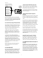
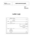
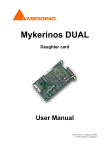
Siemens
Energy & Automation
Application Data
AD353-112
Rev. 1
October 2001
DISCRETE CONTROLLER STATUS OUTPUT
In critical applications, it is often desirable to have a
controller status signal to indicate that the controller
is functional. This publication explains how to
configure a discrete controller status output signal.
The status signal is a normally closed contact that
becomes an open contact in the event of a
catastrophic controller failure. Loss of network
communication detection can be incorporated in the
configuration.
The status output contact is often used to activate a
user supplied annunciator and emergency shutdown
circuit. For example, in a boiler application, the
Burner Management System (BMS) typically
monitors the combustion controller. If the
combustion controller fails, the BMS forces a safety
shut down.
While the reliability of today’s process control
hardware and software is better than ever, the discrete
controller status techniques described here can
provide an additional level of safety. The techniques
developed in this publication require one of the
following controllers and the controller must have the
optional I/O Expander board.
Moore 352P Single-Loop Digital Controller
Moore 353 Process Automation Controller
Moore 354N Universal Loop Controller
Procidia™ i|pac™ Internet Control System
CATASTROPHIC CONTROLLER
FAILURE
The intent of the controller status is to signal a
catastrophic controller failure where the controller is
unable to regulate the process. Non-catastrophic
failures will not activate the controller status but will
initiate an error code as described in the controller’s
User’s Manual (refer to Reference Publications
section).
A catastrophic controller failure is usually a hardware
failure. A probable scenario is the loss of electrical
power to the controller or the failure of the
controller’s internal power supply. A failure of the
microprocessor (hardware or software) is much less
probable, but it too would render the controller nonfunctional. Loss of an analog input or output would
be catastrophic since the process variable could not
be measured or controlled.
INTERNAL WATCHDOG AND
CONTROLLER RESET
The controller CPU has two internal watchdogs that
monitor controller operation. One is software and the
other is hardware. The microprocessor periodically
resets the watchdog timers. In the event that a
watchdog fails to be reset, that watchdog will force a
controller reset. During the reset, all on-board analog
outputs go to zero mA and all on board discrete
outputs go to logic state zero.
CONTROLLER STATUS SIGNAL
The basic controller status signal is built by
configuring the output of a NOR function block to
input C of an ROUT1 or ROUT2 relay output
function block, as shown in the figure below. ROUT
is a mechanical relay located on the I/O Expander
board. Relay contacts are available for user wiring at
the controller terminals. This configuration will
energize the relay output and maintain the normally
open contact closed during normal operation. In the
event of a catastrophic failure, the normally open
contact will open. Therefore, the controller status
signal, at terminals 28 and 29 in the figure on the
next page, is a closed contact during normal
controller operation and an open contact when a
controller fails. The ROUT block must be configured
for direct (Dir) “Action.”
AD353-112
Optional connections to
expand Controller Status
capability.
“On-Line Error and Station Status Codes” table
located in the Error Codes section of the User’s
Manual. Only the error codes mapped to Modbus
register 40002 and LIL channel 4 affect the Station
Error bit. These codes are listed on page 3.
Controller
Terminals,
Moore 353
Shown
QS (Quality Status)
output from AIN, DIN,
or other I/O block.
NC
NOR
QS (Quality Status)
output from AIL block or
i|pac Ubus i|o block.
See text for Delay
Timer recommendation.
27
MG00400a
SE (Station Error)
from ODA, ODC or
other block.
28
ROUT1
NO
29
To incorporate the Station Error into the controller
status connect any SE output to a NOR block input,
as shown in the figure.
ANALOG INPUT/OUTPUT QUALITY
STATUS
The AIN (Analog Input) and AOUT (Analog Output)
blocks have a Quality Status output. This output is
normally low and goes high when the quality status is
“bad.”
There are two typical scenarios for a catastrophic
failure. The most likely is a power failure, either loss
of power to the controller or failure of the controller’s
power supply. The second, which is less likely, is the
failure of the microprocessor.
For an AIN block, a high at the QS output indicates
that there is an A/D conversion failure or that the 1-5
Vdc input signal is below 0.6 V. The low voltage
input signal implies an open circuit or possibly a
failed transmitter or other field device. Note that
when a 2-wire transmitter fails it will not necessarily
cause the output current to fall below 2.4 mA.
Loss of external power to the controller will allow the
relay contacts to open signaling a catastrophic failure.
The controller’s internal power supply provides two
output voltages: 5 Vdc and 24 Vdc. The 5V source is
used to power the CPU and the discrete I/O. The
24V source powers the standard analog inputs and
outputs and to energize the ROUT relays.
For an AOUT block, a high at the QS output
indicates a high impedance or an open circuit.
If an analog block quality status is to be included in
the controller status circuit, connect the Output QS to
a NOR block input as shown above. The AOUT
open circuit conditioned is already included in the
Station Error bit.
A failure of the 5V power source will cause the
microprocessor to shut down. This will trip the
hardware watchdog and cause a controller to reset.
During the reset, the normally open relay contacts
will open.
A 24 Vdc power source failure will allow the
microprocessor to remain functional but the ROUT
normally open relay contacts will open due to lost of
power. The loss of the 24 Vdc power source is
catastrophic because it is possible to have a live
controller but no analog I/O. For this reason, in the
configuring of the Controller Status, use of an ROUT
block is recommended over a DOUT (Discrete
Output) block.
DISCRETE INPUT QUALITY STATUS
The DIN (Discrete Input) blocks have a Quality
Status output. A high at the QS output indicates a
hardware failure in the conversion circuit. This
output can be connected to the NOR block as well.
I/O COMMUNICATION BLOCKS QUALITY
STATUS
In the second scenario, where the microprocessor
fails, the watchdog will reset the controller as
described above.
The quality status of an AIL (Analog Input Local
Instrument Link) or Ethernet communication block
implies a loss of network communication. This is
also true of the Ubus communication between the
i|pac controller and i|o™ modules. Communication
networks may experience brief disruptions causing
the quality status to momentarily go high. A delay
timer (DYT) filter is recommended if these points are
to be included in the controller status.
STATION ERROR BIT
The ODC (Operator Display for Controllers) and the
ODA (Operator Display for Analog Indication &
Alarming) operator display blocks have a Station
Error output. When the controller senses a severe
controller error condition, the Station Error bit is set
high. The list of controller errors is found in the
2
AD353-112
Summary
type and in the subsequent list locate the needed
publication. Printed copies are available through your
local Siemens Energy & Automation, Inc., Process
Industries Division representative.
• Moore 352P Single Loop Digital Controller
User’s Manual, UM352P-1
• Moore 353 Process Automation Controller
User’s Manual, UM353-1
• Moore 354N Universal Loop Controller User’s
Manual, UM354N-1
• Procidia i|pac Internet Control System User’s
Manual, UMiPAC-1
The controller status signal available from the listed
controllers provides an easily configured safety
feature. By carefully selecting NOR gate inputs, the
capability of the controller status can be customized
to satisfy the needs of the process.
Reference Publications
The following publications are available in PDF
(Portable Document Format) at the Siemens Internet
site. Visit www.sea.siemens.com/ia/. In the Quick
Download area of the page, select the desired product
Error Codes
Error Code
MPU A/D
EXP A/D
AOUT1 OC
AOUT2 OC
AOUT3 OC
AINU1 AD
AINU1 TC
AINU1 RJ
AINU2 AD
AINU2 TC
AINU2 RJ
DINU1 E1
DINU2 E1
LIL ERR
LIL NUI
MOD ERR
LON ERR
LON NUI
Watchdog
LOW BAT
RCB->MEM
CYCLETIME
BURNFAIL
RCB FAIL
NO EXPBD
PEB FAIL
IP OVRUN
MB OVRUN
Description
MPU Controller Board A/D Error
I/O Expander board A/D Error
MPU Controller Board D/A #1 Open Circuit
MPU Controller Board D/A #2 Open Circuit
MPU Controller Board D/A #3 Open Circuit
I/O Expander Board Universal Analog Input #1 A/D Error
I/O Expander Board Universal Analog Input #1 T/C Burnout
I/O Expander Board Universal Analog Input #1 Reference Junction Error
I/O Expander Board Universal Analog Input #2 A/D Error
I/O Expander Board Universal Analog Input #1 T/C Burnout
I/O Expander Board Universal Analog Input #2 Reference Junction Error
I/O Expander Board Universal Digital Input #1 Underflow Error
I/O Expander Board Universal Digital Input #2 Underflow Error
LIL Port Error
LIL Non Updating Error
Modbus Port Error
LON Port Error
LON Non Updating Error
Watchdog Timeout
Low NVRAM Battery Voltage
Press STORE to Load RCB Configuration into MPU Memory
Cycle Time Overrun
Flash Memory Burn Failed
RCB Board Failure
Expander Board Not Installed
Ethernet Board Failure
Ethernet Board TCP Communication Failure
Modbus Communication Failure
n
Copyright © 2001, Siemens Energy & Automation, Inc.
Procidia, i|pac, and i|o are trademarks of Siemens Energy & Automation, Inc. Other trademarks are the property of their respective owners.
Siemens Energy & Automation, Inc. assumes no liability for errors or omissions in this document or for the application and use of information
included in this document. The information herein is subject to change without notice. Customers are urged to consult a Siemens Energy &
Automation, Process Industries Division sales representative to confirm availability and specifications.
3