1
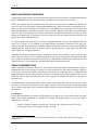
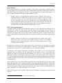
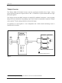
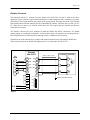
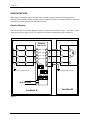
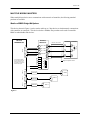
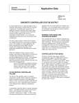
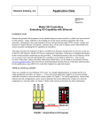
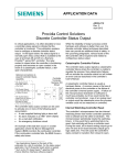
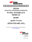
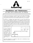
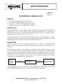
APPLICATION DATA AD353-108 Rev 1 May 1998 RS485 MODBUS COMMUNICATION BENEFITS ◊ ◊ ◊ ◊ Remote monitoring and control of multiple stations Use standard communication devices (wire, radio, fiber, ..) Integration with APACS ACM Modbus Master serial port Integration with any DCS having Modbus RTU capability INTRODUCTION This paper discusses the use of the Modbus™ RS485 network interface included as a standard feature in each Model 352P, 353, and 354 controller. Various connection arrangements will be discussed and illustrated. The data that can be obtained using the Modbus protocol are listed in an appendix section in each controller’s user’s manual (e.g. UM353-1 for 353). The Modbus protocol was developed by Gould Inc. for Modicon™ PLCs. Many companies have adopted this protocol and it has become an industry accepted standard. Detailed technical information can be found at the Modicon internet site [http://www.modicon.com/techpubs/technica.htm]. BACKGROUND A host device, such as a personal computer, communicates with a controller in a command/response format. A controller will respond to a command containing its unique address that is issued from a single host device. Two terminals are included on each controller for connecting the 2-wire RS485 multi-drop network. However, most host devices communicate through an RS232 communication port. This paper identifies several devices for connecting an RS232 communication port to an RS485 network, and it shows the connections to the products used in these applications. Typical timing information is also provided so that the response time of an application can be evaluated. This is particularly important when multiple loops/stations are communicating with a single host device. Controller: Model 352P, Model 353, or Model 354 RS485 RS232/RS485 Bidirectional Converter RS232 Host Device, Often A Personal Computer There are applications where multiple host devices must communicate over a single network. The use of the Modicon BM85 Bridge/Multiplexer for this application is described later in this paper. MOORE PRODUCTS CO., Spring House, PA 19477-0900 An ISO 9001 registered company. AD353-108 BASIC RS232/RS485 CONVERSION A bidirectional signal converter is used to perform the signal conversion needed for communication between RS232 and RS485 ports. Several considerations will affect the successful use of a converter. RS232 uses separate lines for transmitted data (Tx) and received data (Rx). In addition, the host device may use a some or all of the RS232 hardware handshaking lines. Since the controller communicates over a single wire pair, the transmit and receive transceivers on the RS485 side are common in the converter and hardware handshaking is not used between the converter and the controller. When data is received from the host to be sent to the controller, the converter must turn on its RS485 transmit transceiver and turn off its RS485 receive transceiver. It must then reverse this action to receive the response from the controller and forward the response to the host device. In a typical application a host device will send a command and then wait for a pre-configured time-out period for a response to be returned. In the RS232/RS485 applications discussed in this paper, the converter uses the data from the host to control its RS485 transceivers. Some converters can use the RS232 handshaking lines from the host but different software applications may control these lines differently which could result in improper operation. Controllers are usually located some distance from the host device. Since the RS232 cable is limited to less than 50 feet, the converter will be located near the host device with the converter connected to the same power ground as the host. The controller will usually be connected to a different power ground so use of an isolated converter is recommended to isolate the power and the communication lines. TIMING CONSIDERATIONS When a command is sent from a host device, the controller receives the request and sends back a response. Although the time for the exchange is usually very short, the host device may send out multiple requests in a scan cycle to obtain all the data it needs from each control loop. If the host device is a HMI (Human Machine Interface) used for plant operation, certain data is requested only when displayed on the screen. Other data, such as alarm status and data, that will be logged in a trend file will usually be requested on each scan cycle. Several benchmarks and examples follow. These can be used to approximate the overall scan cycle of the host device. The baud rate selected was 19.2K which is suitable for most applications. Increasing the baud rate to 38.4K will not improve the performance significantly due to the turn-around time in the host PC and the controller: Coil Requests: In most HMI applications, coil requests will be made to every loop on every scan cycle since the loop status and the alarm status information are contained in coil data. The response time to get loop coil data is approximately 150 msec.⊕ Example: Assume a Modbus network with 5 stations and 4 loops per station. The scan time to retrieve all coil data is approximately 3 seconds. ⊕ One loop at a time can be requested since the maximum number of coils that can be requested with a single command is 48. 2 AD353-108 Integer Requests: Process, Setpoint, and Valve information is available in scaled form as integer data in a Modbus register. Up to 60 registers can be requested with a single command. Most integer data is located in the same area so that multiple loops can be requested a one time.⊕ A typical response time to acquire a single integer is 70 msec.; to acquire 10 integer values requires approximately 150 msec. Example: Assume a 5 loop group from 5 different stations is displayed. This requires 5 individual requests for 3 integer values. Using the 150 msec response as worse case yields a total of 0.75 seconds. Also, the process and setpoint from each loop is logged in a trend file and is scanned on every scan cycle. Assuming worse case, that the HMI scanner will request an individual response from each loop for a total of 20 requests, the total time will be approximately 2 seconds. Most HMI scanners, however, will combine the requests to each station which will reduce the time to approximately 1 second. REAL (Floating Point) Requests: Floating Point data is available in two consecutive registers. In some cases the most significant word is positioned first, in others last. The controller allows the registers to be formatted either way. Reverse is most common and is the controller default. Most of the range scaling information, such as tuning, is contained in this format and is usually requested when viewed on the screen. A typical response time to acquire a single REAL is approximately 100 msec.; to acquire 10 REAL values requires approximately 180 msec. Example: Assume a loop detail screen is displayed which uses 4 Integer values and 20 REAL values. Since some values are accessed at different locations in the Modbus mapping, 4 separate requests for 5 REAL values will be needed. Approximately 1 second is needed to retrieve this data. From the above example of 5 stations and 4 loops per station, the scan time will typically be 5-6 seconds. In many cases this is satisfactory for a HMI application. However, if the number of stations is doubled, a typical scan time would be 10-12 seconds which in most cases will not be acceptable. An alternative when multiple loops/stations are connected to an HMI is to use the optional Local Instrument Link (LIL) interface. The LIL network has a global database of up to 1600 variables that update in the Model 320 Independent Computer Interface every 500 msec. In most applications, when global data is used for operator display information, an update on the operator display will be made every 1-2 seconds regardless of the number of loops/stations. Tuning, range and other information is contained in parameter data and is requested only when viewed on the screen for the first time and does not require constant updating. When controllers are used in remote monitoring applications where loops are monitored periodically, rather than a HMI application where constant scanning for alarm status and data for trending is required, the maximum number of stations is 32, the physical limitation of an RS485 network. In this type of application the command/response timing still applies but usually only a few loops at a time are monitored on the host display and updates are normally in the order of a few seconds. In the following pages, several converters will be discussed. In addition, a wiring diagram is shown for each converter. ⊕ See the appendix in the controller user’s manual for more details. 3 AD353-108 Telebyte Converter The Telebyte Model 245 Isolated Converter meets the requirements described above. Figure 1 shows typical connections between a single host device and 1-32 controllers at a plant location that has a single point system ground. The Telebyte converter has DB25 connectors for both RS232 and RS485 connections. A cable assembly that provides wire terminations corresponding to pins 2 and 14 must be constructed to connect the Telebyte to the controller.⊕ Switch settings should be as shown in the figure. All controllers are wired together in a bus configuration and a 120Ω network terminating resistor is installed on the last station. . Telebyte Model 245 Controller Controller + + - - c c Host DB25 DB25 120 ohm DB25 Switch Settings SW1-1 --- OFF SW1-2 --- OFF SW1-3 --- ON SW1-4 --- OFF SW2-1 --- ON SW2-2 --- ON SW2-3 --- OFF Single Point System Ground . Figure 1 ⊕ Refer to the Telebyte literature supplied with the converter for current information. 4 AD353-108 Entrelec Converter The Entrelec® 084.233.11 Isolated Converter (Moore PN 16055-395) can also be used in the above application. Figure 2 shows a typical connection between a single host device and a controller (or up to the maximum of 32) at a plant location with a single point system ground. This figure shows the 3-wire hookup between the Entrelec and the controller that is recommended by Entrelec. The host device in this case is a PC. Other devices such as an APACS ACM serial port will require that the Transmit and Receive connections be reversed. The Entrelec converter has screw terminals for both the RS485 and RS232 connections. The default jumper settings are satisfactory but should be verified with the figure. All controllers are wired together in a bus configuration and a 120Ω network terminating resistor is installed on the last station. The Entrelec provides external supply voltages and terminal connections for polarizing the RS485 lines. These must be connected as shown in the figure where 0V is connected to P- and 5V to P+. . Entrelec 084.233.11 Controller L CTRL TxD+ A Tx 3 M RxD RxD+ B Rx 2 K TxD TxD- D SG 5 G COM RxD- E DTR CTS J C P+ P0V 5V VV+ F + + - - c c 120 ohm DB9/M 8.5 - 26 Vdc Controller Belden No. 9842, 24 AWG PC Jumper Settings Single Point System Ground Rt R E . Figure 2 5 AD353-108 RS485 REPEATERS When single or multiple groups of controllers are mounted in separate plant locations that may have different system grounds, isolated repeaters will both extend the distance of a standard RS485 network and isolate the two system grounds from the RS485 network. Entrelec Repeater The Entrelec 084.12.14 Isolated Repeater meets the requirements described. Figure 3 illustrates a typical connection between a group of PAC353 controllers at location A and another group at location B. . Controller + + - c - c Entrelec 084.212.14 M TxD+ TxD+ D J RxD+ RxD+ A G TxD- TxD- F K RxD- RxD- C H E INT3 1 2 3 4 Controller Controller + + - - c c 120 ohm Controller B 1 1 1 0 INT4 1 2 3 4 5 6 Single Point A System Ground 1 1 1 0 0 0 Single Point B System Ground INT1 INT2 1 2 3 4 1 2 3 4 1 1 1 1 0 0 0 0 19.2K Baud 20.4 - 28.8 Vdc VV+ Location B Location A Figure 3 6 AD353-108 MULTIPLE MODBUS MASTERS Where multiple host devices are to communicate with a network of controllers, the following standard products are available. Modicon BM85 Bridge/Multiplexer This device, shown in Figure 4, can be used to enable up to 3 host devices to simultaneously communicate with controllers on a network. This device also has a Modbus Plus port that can be used to extend the BM85 to other Modbus Plus devices. . . Entrelec 084.233.11 L CTRL TxD+ A M RxD RxD+ B Rx 2 K TxD TxD- D SC 5 G COM RxD- DB9 Tx PORT 4 Controller 3 * Pins 4 (DTR) & 6 (DSR) and pins 7 (RTS) & 8 (CTS) should be jumpered. This port should be configured as a Network (slave) port. 8.5 - 26 Vdc P+ P0V 5V VV+ + + - - c c E C * Controller Belden No. 9842, 24 AWG 120 ohm Modicon NW-BM85-000 F Jumper Settings Single Point System Ground Rt R E PORT 3 DB9 Host 3 Null Modem PORT 2 DB9 Host 2 Null Modem PORT 1 DB9 Null Modem Host 1 . Figure 4 7 AD353-108 The Moore logo and APACS are registered trademarks of Moore Products Co. Modicon and Modbus are trademarks of AEG Schneider Automation, Inc. Other trademarks are the property of their respective owners. Moore Products Co. assumes no liability for errors or omissions in this document or for the application and use of information included in this document. The information herein is subject to change without notice. Moore Products Co. is not responsible for changes to product functionality after the publication of this document. Customers are urged to consult with a Moore Products Co. sales representative to confirm the applicability of the information in this document to the product they purchased. n 8